Embed Size (px)
Citation preview
Aermecparticipate in the EUROVENTprogram: LCPthe products are present on the sitewww.eurovent-certification.com
IWRLIY. 1403. 5890961_05
REVERSIBLE HEAT PUMPS - Installation Maintenance Manual
WRL-H025/160
HEAT PUMP WATER/WATER • INDOOR UNITS• HIGH EFFICENCY• PRODUCTION OF HOT WATER UP TO 60 °• FOR GEOTHERMAL APPLICATION
EN

AERMEC S.p.A. reserves the right at any moment to make any modifications considered necessary to improve our products and is not obliged to add these modifications to machines that have already been fabricated, delivered or are under construction.
Dear Customer,Thank you for choosing an AERMEC product. This product is the result of many years of experience and in-depth engineering research, and it is built using top quality materials and advanced technologies.In addition, the CE mark guarantees that our appliances fully comply with the requirements of the European Machinery Directive in terms of safety. We constantly monitor the quality level of our products, and as a result they are synonymous with Safety, Quality, and Reliability.
Product data may be subject to modifications deemed necessary for improving the product without the obligation to give prior notice.
Thank you again.AERMEC S.p.A
I N D E X
1. General warnings ...............................................................61.1. Preservationofthedocumentation ....................................... 61.2. Warningsregardingsafetyandinstallationstandards ...........6
2. Productidentification .........................................................62.1. Technicalplateposition .......................................................... 6
3. Presentation .......................................................................7
4. System example .................................................................7
5. Receiptoftheproductandinstallation ...............................8
6. WRL-H dimensional tables .................................................9
7. Main hydraulic circuits WRL-H ......................................... 117.1. InternalandexternalhydrauliccircuittoWRL-H/standard .117.2. HydrauliccircuitWRL-H/pumps ......................................... 137.3. HydrauliccircuitWRL-HA/storagetankandpump ............15
8. PositionantivibrationWRL-H/WRL-HA .......................... 17
9. WRL-Hhydraulicconnectionsposition ............................. 19
10. WRL-HAhydraulicconnectionsposition ........................... 20
11. Seasonchangeover ........................................................... 2211.1. Electricaldata ....................................................................... 23
12. Wiring diagram ................................................................. 24
13. Modbuselectricalconnection ........................................... 25
14. Extraordinary maintenance .............................................. 26
15. Routinemaintenance ....................................................... 26
4 IWRLIY. 1403. 5890961_05
WRL-H
AERMEC S.p.A.37040 Bevilacqua (VR) Italy–Via Roma, 996Tel. (+39) 0442 633111Telefax 0442 93730–(+39) 0442 93566www.aermec.com - [email protected]
EC DECLARATION OF CONFORMITY We, the undersigned, hereby declare under our own responsibility that the assembly in question, defined as follows:
NAME WRL-H
TYPE WATER-COOLED REVERSIBLE HEAT PUMP
MODEL
To which this declaration refers, complies with the following harmonised standards:
IEC EN 60335-2-40 Safety standard regarding electrical heat pumps, air conditioners and dehumidifiers
IEC EN 61000-6-1 IEC EN 61000-6-3 Immunity and electromagnetic emissions for residential environments
IEC EN 61000-6-2 IEC EN 61000-6-4 Immunity and electromagnetic emissions for industrial environments
EN378 Refrigerating systems and heat pumps - Safety and environmental requirements
UNI EN 12735UNI EN 14276
Seamless, round copper tubes for air conditioning and refrigerationPressure equipment for cooling systems and heat pumps
Therefore complying with the essential requirements of the following directives:
- LVD Directive: 2006/95/CE- Electromagnetic Compatibility Directive 2004/108/CE- Machinery Directive 2006/42/CE- PED Directive regarding pressurised devices 97/23/CEThe product, in agreement with Directive 97/23/CE, satisfies the Total quality Guarantee procedure (form H) with certificate n.06/270-QT3664 Rev.6 issued by the notified body n.1131 CEC via Pisacane 46 Legnano (MI) - Italy La persona autorizzata a costituire il fascicolo tecnico è: / The person authorised to compile the technical file is: / La personneautorisée à constituer le dossier technique est: / Die Person berechtigt, die technischen Unterlagen zusammenzustellen:
Alberto Foroni
Bevilacqua 15/04/2010
Marketing ManagerSignature
5IWRLIY. 1403. 5890961_05
1. GENERAL WARNINGS
The AERMEC WRL-H heat pumps are constructed according to the recognised technical standards and safety regulations. They have been designed for air conditioning and the production of domestic hot water and must be destined to this use compatibly with their performance features. Any contractual or extracontractual liability of the Company is excluded for injury/damage to persons, animals or objects owing to installation, regulation and maintenance errors or improper use. All uses not expressly indicated in this manual are prohibited.
1.1. PRESERVATION OF THE DOCUMENTATION
The instructions along with all the related documentation must be given to the user of the system, who assumes the responsibility to conserve the instructions so that they are always at hand in case of need. Read this sheet carefully; the execution of all works must be performed by qualified staff, according to Standards in force ion this subject in different countries. (Ministerial Decree 329/2004). It must be installed in a way to make maintenance and/or repair operations possible. The appliance warranty does not cover the costs for ladder trucks, scaffolding, or other elevation systems that may become necessary for carrying out servicing under warranty. Do not modify or tamper with the chiller as dangerous situations can be
created and the manufacturer will not be liable for any damage caused. The validity of the warranty shall be void in the event of failure to comply with the above-mentioned indications.
1.2. WARNINGS REGARDING SAFETY AND INSTALLATION STANDARDS
− The cooler must be installed by a qualified and suitably trained technician, in compliance with the national legislation in force in the country of destination (Ministerial Decree 329/2004). AERMEC will not assume any responsibility for damage due to failure to follow these instructions.
− Before beginning any operation, READ THESE INSTRUCTIONS CAREFULLY AND CARRY OUT THE SAFETY CHECKS TO AVOID ALL RISKS. All the staff involved must have thorough knowledge of the operations and any dangers that may arise at the moment in which the installation operations are carried out.
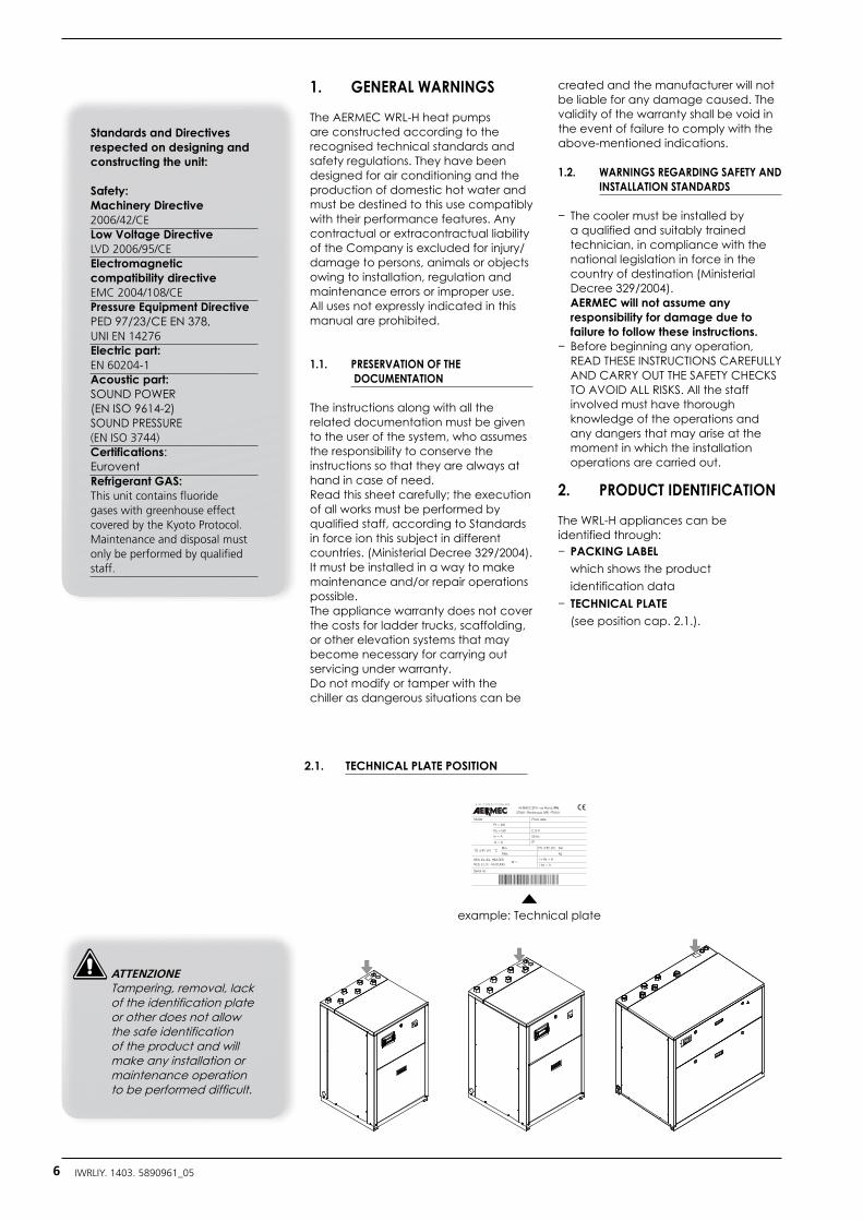
2. PRODUCT IDENTIFICATION
The WRL-H appliances can be identified through:− PACKING LABEL
which shows the product identification data
− TECHNICAL PLATE (see position cap. 2.1.).
example: Technical plate
2.1. TECHNICAL PLATE POSITION
Standards and Directives respected on designing and constructing the unit:
Safety: Machinery Directive 2006/42/CELow Voltage DirectiveLVD 2006/95/CEElectromagnetic compatibility directiveEMC 2004/108/CEPressure Equipment Directive PED 97/23/CE EN 378, UNI EN 14276Electric part: EN 60204-1Acoustic part:SOUND POWER(EN ISO 9614-2)SOUND PRESSURE (EN ISO 3744) Certifications: EuroventRefrigerant GAS: This unit contains fluoride gases with greenhouse effect covered by the Kyoto Protocol. Maintenance and disposal must only be performed by qualified staff.
ATTENZIONE Tampering, removal, lack of the identification plate or other does not allow the safe identification of the product and will make any installation or maintenance operation to be performed difficult.
6 IWRLIY. 1403. 5890961_05
3. PRESENTATION
AERMEC presents the new WRL-H units, OPTIMISED HEAT PUMPS FOR GEOTHER-MIC SYSTEMS water-cooled and func-tioning with R410A refrigerant.
They are INDOOR UNITS with her-metic scroll compressors that respond perfectly to the requirements of the residential market.
High performanceThese units have been designed optimising functioning in heat pump mode, allowing to reach high efficiencies.
Easy installationThe electric and hydraulic connections are all positioned in the upper part of the unit facilitating the installation
and maintenance operations. This also allows to reduce the technical spaces and their positioning in as smaller space possible.
SilenceThe WRL-H units are distinguished for its working silence. Careful soundproofing of the unit with suitable sound-absorbent material confer all units with noise limits such to consent the use of the WRL-H also in homes and not necessarily in dedicated technical rooms.
Dynamic set pointThe electronic regulation, via the aid of AN EXTERNAL AIR TEMPERATURE PROBE (ACCESSORY) and on the basis of the external conditions automatically modify the set point of the system water temperature , improving the
energy efficiency of the system.
Optimized for:
1. GEOTHERMIC SYSTEMS For the production of water for heating systems with FAN COILS, RADIANT PANELS or LOW TEMPERA-TURE RADIATORS, up to 60° C.
2. PRIORITY TO THE PRODUCTION OF DOMESTIC HOT WATER (DHW). The production of hot water with priority logic is guaranteed in both summer and winter.
V3V
1
2
3
13 13
4
5
9
10
12
I II I II
6
7
8
M 7 7 6
7
8
M
1514
7 7
11
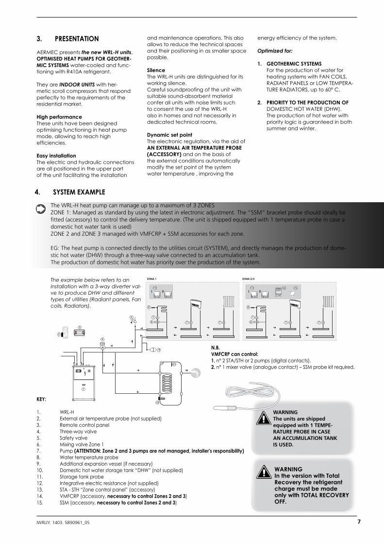
ZONA 1 ZONA 2/3
N.B.VMFCRP can control:1. n° 2 STA/STH or 2 pumps (digital contacts).2. n° 1 mixer valve (analogue contact) – SSM probe kit required.
WARNINGThe units are shipped equipped with 1 TEMPE-RATURE PROBE IN CASE AN ACCUMULATION TANK IS USED.
4. SYSTEM EXAMPLE
The WRL-H heat pump can manage up to a maximum of 3 ZONES ZONE 1: Managed as standard by using the latest in electronic adjustment. The “SSM” bracelet probe should ideally be fitted (accessory) to control the delivery temperature. (The unit is shipped equipped with 1 temperature probe in case a domestic hot water tank is used)ZONE 2 and ZONE 3 managed with VMFCRP + SSM accessories for each zone.
EG: The heat pump is connected directly to the utilities circuit (SYSTEM), and directly manages the production of dome-stic hot water (DHW) through a three-way valve connected to an accumulation tank.The production of domestic hot water has priority over the production of the system.
The example below refers to an installation with a 3-way diverter val-ve to produce DHW and different types of utilities (Radiant panels, Fan coils, Radiators).
KEY:
1. WRL-H2. External air temperature probe (not supplied)3. Remote control panel4. Three-way valve5. Safety valve6. Mixing valve Zone 17. Pump (ATTENTION: Zone 2 and 3 pumps are not managed, installer's responsibility) 8. Water temperature probe9. Additional expansion vessel (if necessary)10. Domestic hot water storage tank “DHW” (not supplied)11. Storage tank probe12. Integrative electric resistance (not supplied)13. STA - STH “Zone control panel” (accessory)14. VMFCRP (accessory, necessary to control Zones 2 and 3)15. SSM (accessory, necessary to control Zones 2 and 3)
WARNINGIn the version with Total Recovery the refrigerant charge must be made only with TOTAL RECOVERY OFF.
7IWRLIY. 1403. 5890961_05
FOR THE INSTALLER
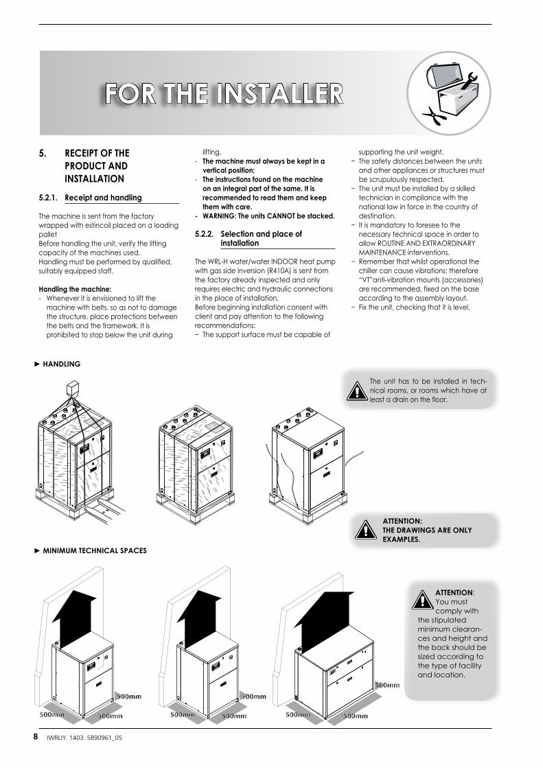
5. RECEIPT OF THE PRODUCT AND INSTALLATION
5.2.1. Receipt and handling
The machine is sent from the factory wrapped with estincoil placed on a loading palletBefore handling the unit, verify the lifting capacity of the machines used. Handling must be performed by qualified, suitably equipped staff.
Handling the machine: - Whenever it is envisioned to lift the
machine with belts, so as not to damage the structure, place protections between the belts and the framework. It is prohibited to stop below the unit during
lifting.- The machine must always be kept in a
vertical position;- The instructions found on the machine
on an integral part of the same. It is recommended to read them and keep them with care.
- WARNING: The units CANNOT be stacked.
5.2.2. Selection and place of installation
The WRL-H water/water INDOOR heat pump with gas side inversion (R410A) is sent from the factory already inspected and only requires electric and hydraulic connections in the place of installation.Before beginning installation consent with client and pay attention to the following recommendations:− The support surface must be capable of
supporting the unit weight.− The safety distances between the units
and other appliances or structures must be scrupulously respected.
− The unit must be installed by a skilled technician in compliance with the national law in force in the country of destination.
− It is mandatory to foresee to the necessary technical space in order to allow ROUTINE AND EXTRAORDINARY MAINTENANCE interventions.
− Remember that whilst operational the chiller can cause vibrations; therefore “VT”anti-vibration mounts (accessories) are recommended, fixed on the base according to the assembly layout.
− Fix the unit, checking that it is level.
► HANDLING
ATTENTION:THE DRAWINGS ARE ONLY EXAMPLES.
500mm500mm
500mm
500mm
500mm
500mm
500mm
500mm 500mm
► MINIMUM TECHNICAL SPACES
ATTENTION:You must comply with
the stipulated minimum clearan-ces and height and the back should be sized according to the type of facility and location.
The unit has to be installed in tech-nical rooms, or rooms which have at least a drain on the floor.
8 IWRLIY. 1403. 5890961_05
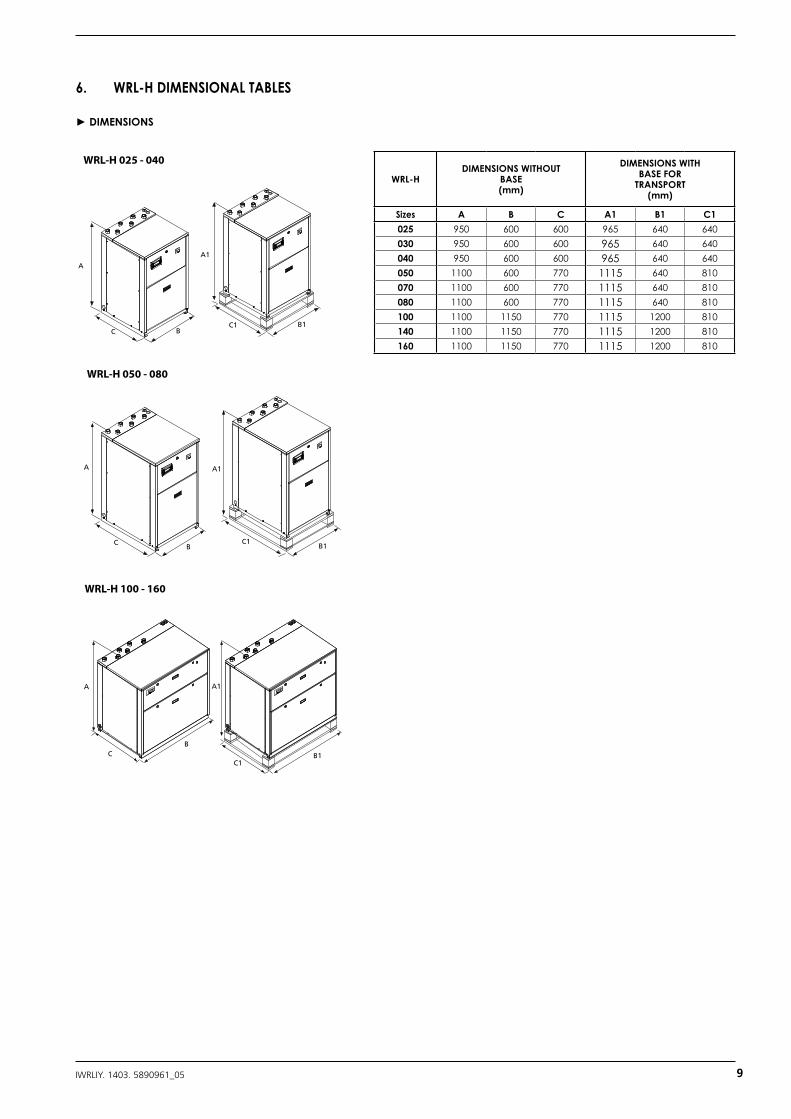
6. WRL-H DIMENSIONAL TABLES
► DIMENSIONS
WRL-HDIMENSIONS WITHOUT
BASE(mm)
DIMENSIONS WITH BASE FOR
TRANSPORT (mm)
Sizes A B C A1 B1 C1025 950 600 600 965 640 640030 950 600 600 965 640 640040 950 600 600 965 640 640050 1100 600 770 1115 640 810070 1100 600 770 1115 640 810080 1100 600 770 1115 640 810100 1100 1150 770 1115 1200 810140 1100 1150 770 1115 1200 810160 1100 1150 770 1115 1200 810
A1
C1B1
A
CB
A1
C1 B1
A
C B
WRL-H 025 - 040 WRL-H 050 - 080 WRL-H 100 - 160
A A1
B
B1CC1
A1
C1B1
A
CB
A1
C1 B1
A
C B
WRL-H 025 - 040 WRL-H 050 - 080 WRL-H 100 - 160
A A1
B
B1CC1
A1
C1B1
A
CB
A1
C1 B1
A
C B
WRL-H 025 - 040 WRL-H 050 - 080 WRL-H 100 - 160
A A1
B
B1CC1
9IWRLIY. 1403. 5890961_05
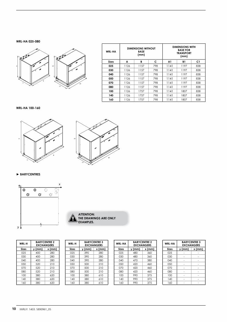
WRL-HA 025-080
WRL-HA 100-160
WRL-HADIMENSIONS WITHOUT
BASE(mm)
DIMENSIONS WITH BASE FOR
TRANSPORT (mm)
Sizes A B C A1 B1 C1025 1126 1157 798 1141 1197 838030 1126 1157 798 1141 1197 838040 1126 1157 798 1141 1197 838050 1126 1157 798 1141 1197 838070 1126 1157 798 1141 1197 838080 1126 1157 798 1141 1197 838100 1126 1757 798 1141 1807 838140 1126 1757 798 1141 1807 838160 1126 1757 798 1141 1807 838
► BARYCENTRES
WRL-H BARYCENTRE 2 EXCHANGERS
Sizes y (mm) x (mm)025 400 280030 400 280040 400 280050 520 210070 520 210080 520 210100 380 620140 380 620160 380 620
WRL-HA BARYCENTRE 2 EXCHANGERS
Sizes y (mm) x (mm)025 480 360030 480 360040 470 380050 420 460070 420 460080 420 460100 990 375140 990 375160 990 375
WRL-H BARYCENTRE 3 EXCHANGERS
Sizes y (mm) x (mm)025 390 280030 390 280040 390 280050 500 210070 500 210080 500 210100 380 610140 380 610160 380 610
WRL-HA BARYCENTRE 3 EXCHANGERS
Sizes y (mm) x (mm)025 - -030 - -040 - -050 - -070 - -080 - -100 - -140 - -160 - -
x
y
A
C
B
A1
C1
B1
A
C
B
A1
C1
B1
A
C
B
A1
C1
B1
A
C
B
A1
C1
B1
ATTENTION:THE DRAWINGS ARE ONLY EXAMPLES.
10 IWRLIY. 1403. 5890961_05
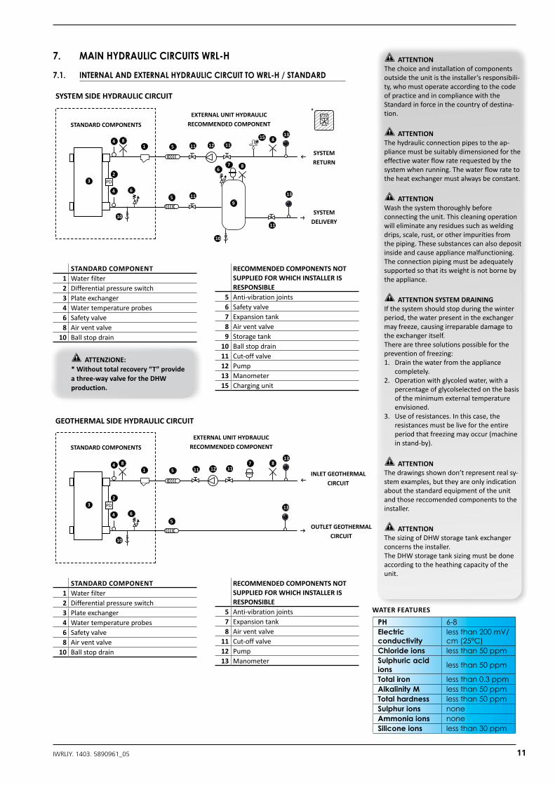
STANDARDCOMPONENT1 Waterfilter2 Differentialpressureswitch3 Plateexchanger4 Watertemperatureprobes6 Safetyvalve8 Airventvalve
10 Ballstopdrain
RECOMMENDEDCOMPONENTSNOTSUPPLIEDFORWHICHINSTALLERISRESPONSIBLE
5 Anti-vibrationjoints6 Safetyvalve7 Expansiontank8 Airventvalve9 Storagetank
10 Ballstopdrain11 Cut-offvalve12 Pump13 Manometer15 Chargingunit
ATTENZIONE:* Withouttotalrecovery“T”provideathree-wayvalvefor theDHWproduction.
7. MAIN HYDRAULIC CIRCUITS WRL-H
7.1. INTERNAL AND EXTERNAL HYDRAULIC CIRCUIT TO WRL-H / STANDARD
STANDARDCOMPONENT1 Waterfilter2 Differentialpressureswitch3 Plateexchanger4 Watertemperatureprobes6 Safetyvalve8 Airventvalve
10 Ballstopdrain
RECOMMENDEDCOMPONENTSNOTSUPPLIEDFORWHICHINSTALLERISRESPONSIBLE
5 Anti-vibrationjoints7 Expansiontank8 Airventvalve
11 Cut-offvalve12 Pump13 Manometer
ATTENTION Thechoiceandinstallationof componentsoutsidetheunit istheinstaller’sresponsibili-ty,who mustoperateaccordingtothe codeofpracticeandincompliance withthe Standardinforceinthe countryofdestina-tion.
ATTENTIONThehydraulicconnectionpipesto theap-pliancemustbesuitablydimensioned fortheeffectivewater flowraterequestedbythesystem whenrunning.Thewaterflowrate totheheatexchangermustalways beconstant.
ATTENTION Washthesystemthoroughlybeforeconnectingtheunit.Thiscleaningoperationwilleliminateanyresiduessuchasweldingdrips,scale,rust,orotherimpuritiesfromthepiping.Thesesubstancescanalsodepositinsideandcauseappliancemalfunctioning.Theconnectionpipingmustbeadequatelysupportedsothatitsweightisnotbornebytheappliance.
ATTENTIONSYSTEMDRAININGIfthesystemshouldstopduringthewinterperiod,thewaterpresentintheexchangermayfreeze,causingirreparabledamagetotheexchangeritself.Therearethreesolutionspossibleforthepreventionoffreezing:1. Drainthewaterfromtheappliance
completely.2. Operationwithglycoledwater, witha
percentageofglycolselectedonthebasisofthe minimumexternaltemperature envisioned.
3. Use ofresistances. Inthiscase,theresistances mustbelivefortheentire periodthatfreezingmayoccur (machineinstand-by).
ATTENTIONThedrawingsshowndon’trepresentrealsy-stemexamples,buttheyareonlyindicationaboutthestandardequipmentoftheunitandthosereccomendedcomponentstotheinstaller.
ATTENTIONThesizingofDHWstoragetankexchangerconcernstheinstaller.TheDHWstoragetanksizingmustbedoneaccordingtotheheathingcapacityoftheunit.
3 PD
4
4125
5
1
2
8
8
8
13
7
11
6
6
6
6
6
9
10
10
1111
11
13
11
11
3
45
5
18
8
13
7
7
11
6
14
18
16
10
10
13
12 1111
CIRCUITO IDRAULICO LATO UTENZE
RITORNO UTENZE
*COMPONENTI FORNITI
DI SERIE COMPONENTI NON FORNITI CONSIGLIATI
COMPONENTI NON FORNITI CONSIGLIATI
COMPONENTI NON FORNITI CONSIGLIATI
COMPONENTI NON FORNITI CONSIGLIATI
COMPONENTI FORNITIDI SERIE
COMPONENTI FORNITIDI SERIE
COMPONENTI FORNITIDI SERIE
MANDATA UTENZE
INGRESSO ACQUA SANITARIO
USCITA ACQUA SANITARIO
INGRESSO ACQUA ESTERNA
USCITA ACQUA ESTERNA
CIRCUITO IDRAULICO LATO GEOTERMICO
CIRCUITO IDRAULICO LATO SANITARIO (ACCUMULO SANITARIO)
3 PD
4
45
5
1
2
8
13
17
10
13
12 1111
CIRCUITO IDRAULICO LATO POZZO
15
15
RITORNO ANELLO GEO
MANDATA ANELLO GEO
3 PD
4
45
5
1
2
88
8
8
13
11
10
13
127
1111
V3V
19
SYSTEMSIDEHYDRAULICCIRCUIT
STANDARDCOMPONENTSEXTERNALUNITHYDRAULIC
RECOMMENDEDCOMPONENT
SYSTEMRETURN
SYSTEMDELIVERY
3 PD
4
4125
5
1
2
8
8
8
13
7
11
6
6
6
6
6
9
10
10
1111
11
13
11
11
3
45
5
18
8
13
7
7
11
6
14
18
16
10
10
13
12 1111
CIRCUITO IDRAULICO LATO UTENZE
RITORNO UTENZE
*COMPONENTI FORNITI
DI SERIE COMPONENTI NON FORNITI CONSIGLIATI
COMPONENTI NON FORNITI CONSIGLIATI
COMPONENTI NON FORNITI CONSIGLIATI
COMPONENTI NON FORNITI CONSIGLIATI
COMPONENTI FORNITIDI SERIE
COMPONENTI FORNITIDI SERIE
COMPONENTI FORNITIDI SERIE
MANDATA UTENZE
INGRESSO ACQUA SANITARIO
USCITA ACQUA SANITARIO
INGRESSO ACQUA ESTERNA
USCITA ACQUA ESTERNA
CIRCUITO IDRAULICO LATO GEOTERMICO
CIRCUITO IDRAULICO LATO SANITARIO (ACCUMULO SANITARIO)
3 PD
4
45
5
1
2
8
13
17
10
13
12 1111
CIRCUITO IDRAULICO LATO POZZO
15
15
RITORNO ANELLO GEO
MANDATA ANELLO GEO
3 PD
4
45
5
1
2
88
8
8
13
11
10
13
127
1111
V3V
19
GEOTHERMALSIDEHYDRAULICCIRCUIT
STANDARDCOMPONENTSEXTERNALUNITHYDRAULIC
RECOMMENDEDCOMPONENT
INLETGEOTHERMALCIRCUIT
OUTLETGEOTHERMALCIRCUIT
PH 6-8Electricconductivity
less than 200 mV/cm (25°C)
Chloride ions less than 50 ppmSulphuric acidions less than 50 ppm
Total iron less than 0.3 ppmAlkalinity M less than 50 ppmTotal hardness less than 50 ppmSulphur ions noneAmmonia ions noneSilicone ions less than 30 ppm
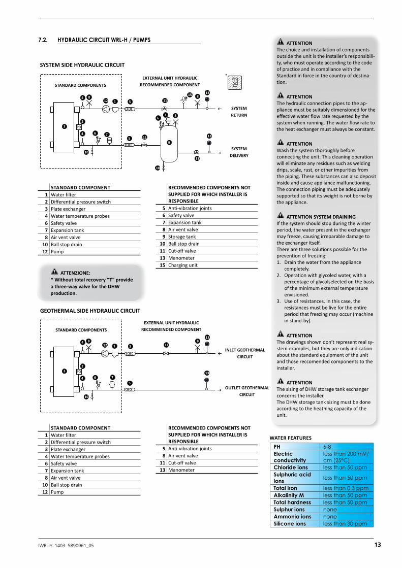
WATERFEATURES
11IWRLIY. 1403. 5890961_05

3 PD
4
4125
5
1
2
8
8
8
13
7
11
6
6
6
6
6
9
10
10
1111
11
13
11
11
3
45
5
18
8
13
7
7
11
6
14
18
16
10
10
13
12 1111
CIRCUITO IDRAULICO LATO UTENZE
RITORNO UTENZE
*COMPONENTI FORNITI
DI SERIE COMPONENTI NON FORNITI CONSIGLIATI
COMPONENTI NON FORNITI CONSIGLIATI
COMPONENTI NON FORNITI CONSIGLIATI
COMPONENTI NON FORNITI CONSIGLIATI
COMPONENTI FORNITIDI SERIE
COMPONENTI FORNITIDI SERIE
COMPONENTI FORNITIDI SERIE
MANDATA UTENZE
INGRESSO ACQUA SANITARIO
USCITA ACQUA SANITARIO
INGRESSO ACQUA ESTERNA
USCITA ACQUA ESTERNA
CIRCUITO IDRAULICO LATO GEOTERMICO
CIRCUITO IDRAULICO LATO SANITARIO (ACCUMULO SANITARIO)
3 PD
4
45
5
1
2
8
13
17
10
13
12 1111
CIRCUITO IDRAULICO LATO POZZO
15
15
RITORNO ANELLO GEO
MANDATA ANELLO GEO
3 PD
4
45
5
1
2
88
8
8
13
11
10
13
127
1111
V3V
19
STANDARDCOMPONENT1 Waterfilter
3 Plateexchanger(TOTALRECOVERY)
4 Watertemperatureprobes6 Safetyvalve8 Airventvalve
10 Ballstopdrain
RECOMMENDEDCOMPONENTSNOTSUPPLIEDFORWHICHINSTALLERISRESPONSIBLE
5 Anti-vibrationjoints6 Safetyvalve7 Expansiontank8 Airventvalve
10 Ballstopdrain11 Cut-offvalve12 Pump13 Manometer14 Storagetank(DHW)15 Chargingunit18 Electricalresistance19 Onewayvalve
STANDARDCOMPONENT1 Waterfilter2 Differentialpressureswitch3 Plateexchanger4 Watertemperatureprobes6 Safetyvalve8 Airventvalve
10 Ballstopdrain
RECOMMENDEDCOMPONENTSNOTSUPPLIEDFORWHICHINSTALLERISRESPONSIBLE
5 Anti-vibrationjoints8 Airventvalve
11 Cut-offvalve12 Pump13 Manometer
16 2-waymodulatingvalve(selectedfromconfigurator)
17 Flowswitch
ATTENTION Thechoiceandinstallationof componentsoutsidetheunit istheinstaller’sresponsibili-ty,who mustoperateaccordingtothe codeofpracticeandincompliance withthe Standardinforceinthe countryofdestina-tion.
ATTENTIONThehydraulicconnectionpipesto theap-pliancemustbesuitablydimensioned fortheeffectivewater flowraterequestedbythesystem whenrunning.Thewaterflowrate totheheatexchangermustalways beconstant.
ATTENTION Washthesystemthoroughlybeforeconnectingtheunit.Thiscleaningoperationwilleliminateanyresiduessuchasweldingdrips,scale,rust,orotherimpuritiesfromthepiping.Thesesubstancescanalsodepositinsideandcauseappliancemalfunctioning.Theconnectionpipingmustbeadequatelysupportedsothatitsweightisnotbornebytheappliance.
ATTENTIONSYSTEMDRAININGIfthesystemshouldstopduringthewinterperiod,thewaterpresentintheexchangermayfreeze,causingirreparabledamagetotheexchangeritself.Therearethreesolutionspossibleforthepreventionoffreezing:1. Drainthewaterfromtheappliance
completely.2. Operationwithglycoledwater, witha
percentageofglycolselectedonthebasisofthe minimumexternaltemperature envisioned.
3. Use ofresistances. Inthiscase,theresistances mustbelivefortheentire periodthatfreezingmayoccur (machineinstand-by).
ATTENTIONThedrawingsshowndon’trepresentrealsy-stemexamples,buttheyareonlyindicationaboutthestandardequipmentoftheunitandthosereccomendedcomponentstotheinstaller.
ATTENTIONThesizingofDHWstoragetankexchangerconcernstheinstaller.TheDHWstoragetanksizingmustbedoneaccordingtotheheathingcapacityoftheunit.
WELLSIDEHYDRAULICCIRCUIT
STANDARDCOMPONENTSEXTERNALUNITHYDRAULIC
RECOMMENDEDCOMPONENT
INLETEXTERNALWATER
OUTLETXTERNALWATER
PH 6-8Electricconductivity
less than 200 mV/cm (25°C)
Chloride ions less than 50 ppmSulphuric acidions less than 50 ppm
Total iron less than 0.3 ppmAlkalinity M less than 50 ppmTotal hardness less than 50 ppmSulphur ions noneAmmonia ions noneSilicone ions less than 30 ppm
WATERFEATURES
3 PD
4
4125
5
1
2
8
8
8
13
7
11
6
6
6
6
6
9
10
10
1111
11
13
11
11
3
45
5
18
8
13
7
7
11
6
14
18
16
10
10
13
12 1111
CIRCUITO IDRAULICO LATO UTENZE
RITORNO UTENZE
*COMPONENTI FORNITI
DI SERIE COMPONENTI NON FORNITI CONSIGLIATI
COMPONENTI NON FORNITI CONSIGLIATI
COMPONENTI NON FORNITI CONSIGLIATI
COMPONENTI NON FORNITI CONSIGLIATI
COMPONENTI FORNITIDI SERIE
COMPONENTI FORNITIDI SERIE
COMPONENTI FORNITIDI SERIE
MANDATA UTENZE
INGRESSO ACQUA SANITARIO
USCITA ACQUA SANITARIO
INGRESSO ACQUA ESTERNA
USCITA ACQUA ESTERNA
CIRCUITO IDRAULICO LATO GEOTERMICO
CIRCUITO IDRAULICO LATO SANITARIO (ACCUMULO SANITARIO)
3 PD
4
45
5
1
2
8
13
17
10
13
12 1111
CIRCUITO IDRAULICO LATO POZZO
15
15
RITORNO ANELLO GEO
MANDATA ANELLO GEO
3 PD
4
45
5
1
2
88
8
8
13
11
10
13
127
1111
V3V
19
STANDARDCOMPONENTS
EXTERNALUNITHYDRAULICRECOMMENDEDCOMPONENT
INLETWATER
OUTLET WATER
DHWHYDRAULICCIRCUIT
12 IWRLIY. 1403. 5890961_05
PH 6-8Electricconductivity
less than 200 mV/cm (25°C)
Chloride ions less than 50 ppmSulphuric acidions less than 50 ppm
Total iron less than 0.3 ppmAlkalinity M less than 50 ppmTotal hardness less than 50 ppmSulphur ions noneAmmonia ions noneSilicone ions less than 30 ppm
WATERFEATURES
7.2. HYDRAULIC CIRCUIT WRL-H / PUMPS ATTENTION Thechoiceandinstallationof componentsoutsidetheunit istheinstaller’sresponsibili-ty,who mustoperateaccordingtothe codeofpracticeandincompliance withthe Standardinforceinthe countryofdestina-tion.
ATTENTIONThehydraulicconnectionpipesto theap-pliancemustbesuitablydimensioned fortheeffectivewater flowraterequestedbythesystem whenrunning.Thewaterflowrate totheheatexchangermustalways beconstant.
ATTENTION Washthesystemthoroughlybeforeconnectingtheunit.Thiscleaningoperationwilleliminateanyresiduessuchasweldingdrips,scale,rust,orotherimpuritiesfromthepiping.Thesesubstancescanalsodepositinsideandcauseappliancemalfunctioning.Theconnectionpipingmustbeadequatelysupportedsothatitsweightisnotbornebytheappliance.
ATTENTIONSYSTEMDRAININGIfthesystemshouldstopduringthewinterperiod,thewaterpresentintheexchangermayfreeze,causingirreparabledamagetotheexchangeritself.Therearethreesolutionspossibleforthepreventionoffreezing:1. Drainthewaterfromtheappliance
completely.2. Operationwithglycoledwater, witha
percentageofglycolselectedonthebasisofthe minimumexternaltemperature envisioned.
3. Use ofresistances. Inthiscase,theresistances mustbelivefortheentire periodthatfreezingmayoccur (machineinstand-by).
ATTENTIONThedrawingsshowndon’trepresentrealsy-stemexamples,buttheyareonlyindicationaboutthestandardequipmentoftheunitandthosereccomendedcomponentstotheinstaller.
ATTENTIONThesizingofDHWstoragetankexchangerconcernstheinstaller.TheDHWstoragetanksizingmustbedoneaccordingtotheheathingcapacityoftheunit.
STANDARDCOMPONENT1 Waterfilter2 Differentialpressureswitch3 Plateexchanger4 Watertemperatureprobes6 Safetyvalve7 Expansiontank8 Airventvalve
10 Ballstopdrain12 Pump
RECOMMENDEDCOMPONENTSNOTSUPPLIEDFORWHICHINSTALLERISRESPONSIBLE
5 Anti-vibrationjoints6 Safetyvalve7 Expansiontank8 Airventvalve9 Storagetank
10 Ballstopdrain11 Cut-offvalve13 Manometer15 Chargingunit
STANDARDCOMPONENT1 Waterfilter2 Differentialpressureswitch3 Plateexchanger4 Watertemperatureprobes6 Safetyvalve7 Expansiontank8 Airventvalve
10 Ballstopdrain12 Pump
RECOMMENDEDCOMPONENTSNOTSUPPLIEDFORWHICHINSTALLERISRESPONSIBLE
5 Anti-vibrationjoints8 Airventvalve
11 Cut-offvalve13 Manometer
ATTENZIONE:* Withouttotalrecovery“T”provideathree-wayvalvefor theDHWproduction.
3 PD
4
412 5
5
1
2
8
8
8
137
7
11
6
6
6
6
6
9
10
10
11
11
13
11
11
3
45
5
18
8
13
7
7
7
11
6
14
18
16
10
10
13
12 11
CIRCUITO IDRAULICO LATO UTENZE
RITORNO UTENZE
*COMPONENTI FORNITI
DI SERIE COMPONENTI NON FORNITI CONSIGLIATI
COMPONENTI NON FORNITI CONSIGLIATI
COMPONENTI NON FORNITI CONSIGLIATI
COMPONENTI NON FORNITI CONSIGLIATI
COMPONENTI FORNITIDI SERIE
COMPONENTI FORNITIDI SERIE
COMPONENTI FORNITIDI SERIE
MANDATA UTENZE
INGRESSO ACQUA SANITARIO
USCITA ACQUA SANITARIO
INGRESSO ACQUA ESTERNA
USCITA ACQUA ESTERNA
CIRCUITO IDRAULICO LATO GEOTERMICO
CIRCUITO IDRAULICO LATO SANITARIO (ACCUMULO SANITARIO)
3 PD
4
45
5
1
2
8
13
17
10
13
11
CIRCUITO IDRAULICO LATO POZZO
15
15
RITORNO ANELLO GEO
MANDATA ANELLO GEO
3 PD
4
45
5
1
2
88
8
8
13
11
10
13
12
7
11
V3V
19
SYSTEMSIDEHYDRAULICCIRCUIT
STANDARDCOMPONENTSEXTERNALUNITHYDRAULIC
RECOMMENDEDCOMPONENT
SYSTEMRETURN
SYSTEMDELIVERY
3 PD
4
412 5
5
1
2
8
8
8
137
7
11
6
6
6
6
6
9
10
10
11
11
13
11
11
3
45
5
18
8
13
7
7
7
11
6
14
18
16
10
10
13
12 11
CIRCUITO IDRAULICO LATO UTENZE
RITORNO UTENZE
*COMPONENTI FORNITI
DI SERIE COMPONENTI NON FORNITI CONSIGLIATI
COMPONENTI NON FORNITI CONSIGLIATI
COMPONENTI NON FORNITI CONSIGLIATI
COMPONENTI NON FORNITI CONSIGLIATI
COMPONENTI FORNITIDI SERIE
COMPONENTI FORNITIDI SERIE
COMPONENTI FORNITIDI SERIE
MANDATA UTENZE
INGRESSO ACQUA SANITARIO
USCITA ACQUA SANITARIO
INGRESSO ACQUA ESTERNA
USCITA ACQUA ESTERNA
CIRCUITO IDRAULICO LATO GEOTERMICO
CIRCUITO IDRAULICO LATO SANITARIO (ACCUMULO SANITARIO)
3 PD
4
45
5
1
2
8
13
17
10
13
11
CIRCUITO IDRAULICO LATO POZZO
15
15
RITORNO ANELLO GEO
MANDATA ANELLO GEO
3 PD
4
45
5
1
2
88
8
8
13
11
10
13
12
7
11
V3V
19
GEOTHERMALSIDEHYDRAULICCIRCUIT
STANDARDCOMPONENTSEXTERNALUNITHYDRAULIC
RECOMMENDEDCOMPONENT
INLETGEOTHERMALCIRCUIT
OUTLETGEOTHERMALCIRCUIT
13IWRLIY. 1403. 5890961_05
STANDARDCOMPONENT1 Waterfilter2 Differentialpressureswitch3 Plateexchanger4 Watertemperatureprobes6 Safetyvalve8 Airventvalve
10 Ballstopdrain
RECOMMENDEDCOMPONENTSNOTSUPPLIEDFORWHICHINSTALLERISRESPONSIBLE
5 Anti-vibrationjoints8 Airventvalve
11 Cut-offvalve13 Manometer
16 2-waymodulatingvalve(selected from configurator)
17 Flowswitch
STANDARDCOMPONENT1 Waterfilter
3 Differentialpressureswitch (TOTALRECOVERY)
4 Watertemperatureprobes6 Safetyvalve
7 Expansiontank(standardsupplyonsize025-080)
8 Airventvalve10 Ballstopdrain12 Pump
RECOMMENDEDCOMPONENTSNOTSUPPLIEDFORWHICHINSTALLERISRESPONSIBLE
5 Anti-vibrationjoints6 Safetyvalve7 Expansiontank8 Airventvalve
10 Ballstopdrain11 Cut-offvalve13 Manometer14 Storagetank(DHW)15 Chargingunit18 Electricalresistance19 Onewayvalve
3 PD
4
412 5
5
1
2
8
8
8
137
7
11
6
6
6
6
6
9
10
10
11
11
13
11
11
3
45
5
18
8
13
7
7
7
11
6
14
18
16
10
10
13
12 11
CIRCUITO IDRAULICO LATO UTENZE
RITORNO UTENZE
*COMPONENTI FORNITI
DI SERIE COMPONENTI NON FORNITI CONSIGLIATI
COMPONENTI NON FORNITI CONSIGLIATI
COMPONENTI NON FORNITI CONSIGLIATI
COMPONENTI NON FORNITI CONSIGLIATI
COMPONENTI FORNITIDI SERIE
COMPONENTI FORNITIDI SERIE
COMPONENTI FORNITIDI SERIE
MANDATA UTENZE
INGRESSO ACQUA SANITARIO
USCITA ACQUA SANITARIO
INGRESSO ACQUA ESTERNA
USCITA ACQUA ESTERNA
CIRCUITO IDRAULICO LATO GEOTERMICO
CIRCUITO IDRAULICO LATO SANITARIO (ACCUMULO SANITARIO)
3 PD
4
45
5
1
2
8
13
17
10
13
11
CIRCUITO IDRAULICO LATO POZZO
15
15
RITORNO ANELLO GEO
MANDATA ANELLO GEO
3 PD
4
45
5
1
2
88
8
8
13
11
10
13
12
7
11
V3V
19
WELLSIDEHYDRAULICCIRCUIT
STANDARDCOMPONENTSEXTERNALUNITHYDRAULIC
RECOMMENDEDCOMPONENT
INLETEXTERNALWATER
OUTLETXTERNALWATER
ATTENTION Thechoiceandinstallationof componentsoutsidetheunit istheinstaller’sresponsibili-ty,who mustoperateaccordingtothe codeofpracticeandincompliance withthe Standardinforceinthe countryofdestina-tion.
ATTENTIONThehydraulicconnectionpipesto theap-pliancemustbesuitablydimensioned fortheeffectivewater flowraterequestedbythesystem whenrunning.Thewaterflowrate totheheatexchangermustalways beconstant.
ATTENTION Washthesystemthoroughlybeforeconnectingtheunit.Thiscleaningoperationwilleliminateanyresiduessuchasweldingdrips,scale,rust,orotherimpuritiesfromthepiping.Thesesubstancescanalsodepositinsideandcauseappliancemalfunctioning.Theconnectionpipingmustbeadequatelysupportedsothatitsweightisnotbornebytheappliance.
ATTENTIONSYSTEMDRAININGIfthesystemshouldstopduringthewinterperiod,thewaterpresentintheexchangermayfreeze,causingirreparabledamagetotheexchangeritself.Therearethreesolutionspossibleforthepreventionoffreezing:1. Drainthewaterfromtheappliance
completely.2. Operationwithglycoledwater, witha
percentageofglycolselectedonthebasisofthe minimumexternaltemperature envisioned.
3. Use ofresistances. Inthiscase,theresistances mustbelivefortheentire periodthatfreezingmayoccur (machineinstand-by).
ATTENTIONThedrawingsshowndon’trepresentrealsy-stemexamples,buttheyareonlyindicationaboutthestandardequipmentoftheunitandthosereccomendedcomponentstotheinstaller.
ATTENTIONThesizingofDHWstoragetankexchangerconcernstheinstaller.TheDHWstoragetanksizingmustbedoneaccordingtotheheathingcapacityoftheunit.
PH 6-8Electricconductivity
less than 200 mV/cm (25°C)
Chloride ions less than 50 ppmSulphuric acidions less than 50 ppm
Total iron less than 0.3 ppmAlkalinity M less than 50 ppmTotal hardness less than 50 ppmSulphur ions noneAmmonia ions noneSilicone ions less than 30 ppm
WATERFEATURES
3 PD
4
412 5
5
1
2
8
8
8
137
7
11
6
6
6
6
6
9
10
10
11
11
13
11
11
3
45
5
18
8
13
7
7
7
11
6
14
18
16
10
10
13
12 11
CIRCUITO IDRAULICO LATO UTENZE
RITORNO UTENZE
*COMPONENTI FORNITI
DI SERIE COMPONENTI NON FORNITI CONSIGLIATI
COMPONENTI NON FORNITI CONSIGLIATI
COMPONENTI NON FORNITI CONSIGLIATI
COMPONENTI NON FORNITI CONSIGLIATI
COMPONENTI FORNITIDI SERIE
COMPONENTI FORNITIDI SERIE
COMPONENTI FORNITIDI SERIE
MANDATA UTENZE
INGRESSO ACQUA SANITARIO
USCITA ACQUA SANITARIO
INGRESSO ACQUA ESTERNA
USCITA ACQUA ESTERNA
CIRCUITO IDRAULICO LATO GEOTERMICO
CIRCUITO IDRAULICO LATO SANITARIO (ACCUMULO SANITARIO)
3 PD
4
45
5
1
2
8
13
17
10
13
11
CIRCUITO IDRAULICO LATO POZZO
15
15
RITORNO ANELLO GEO
MANDATA ANELLO GEO
3 PD
4
45
5
1
2
88
8
8
13
11
10
13
12
7
11
V3V
19
DHWHYDRAULICCIRCUIT
STANDARDCOMPONENTS
EXTERNALUNITHYDRAULICRECOMMENDEDCOMPONENT
INLETWATER
OUTLET WATER
14 IWRLIY. 1403. 5890961_05
STANDARDCOMPONENT1 Waterfilter2 Differentialpressureswitch3 Plateexchanger4 Watertemperatureprobes6 Safetyvalve7 Expansiontank8 Airventvalve9 Storagetank
10 Ballstopdrain12 Pump
RECOMMENDEDCOMPONENTSNOTSUPPLIEDFORWHICHINSTALLERISRESPONSIBLE
5 Anti-vibrationjoints8 Airventvalve
11 Cut-offvalve13 Manometer15 Chargingunit
7.3. HYDRAULIC CIRCUIT WRL-HA / STORAGE TANK AND PUMP
STANDARDCOMPONENT1 Waterfilter2 Differentialpressureswitch3 Plateexchanger4 Watertemperatureprobes6 Safetyvalve7 Expansiontank8 Airventvalve
10 Ballstopdrain12 Pump
RECOMMENDEDCOMPONENTSNOTSUPPLIEDFORWHICHINSTALLERISRESPONSIBLE
5 Anti-vibrationjoints8 Airventvalve
11 Cut-offvalve13 Manometer
3 PD
4
45
5
2
88
13
11
6
6
6
876
9
10
11
13
11
11
3
45
5
8
8
13
7
7
11
6
14
18
10
10
13
11
CIRCUITO IDRAULICO LATO UTENZE
RITORNO UTENZE
COMPONENTI FORNITIDI SERIE
COMPONENTI NON FORNITI CONSIGLIATI
COMPONENTI NON FORNITI CONSIGLIATI
COMPONENTI NON FORNITI CONSIGLIATI
COMPONENTI NON FORNITI CONSIGLIATI
COMPONENTI FORNITIDI SERIE
COMPONENTI FORNITIDI SERIE
COMPONENTI FORNITIDI SERIE
MANDATA UTENZE
INGRESSO ACQUA SANITARIO
USCITA ACQUA SANITARIO
INGRESSO ACQUA ESTERNA
USCITA ACQUA ESTERNA
CIRCUITO IDRAULICO LATO GEOTERMICO
CIRCUITO IDRAULICO LATO SANITARIO (ACCUMULO SANITARIO)
3 PD
4
45
5
1
2
8
13
17
10
13
11
112
CIRCUITO IDRAULICO LATO POZZO
15
15
16
RITORNO ANELLO GEO
MANDATA ANELLO GEO
3 PD
4
45
5
1
2
88
8
8
13
11
10
13
12
7
7
11
112
19
ATTENTION:The DHWproductionisnotpossibleinversionWRL-HA,butispossiblewith“T”versionselectionablefromconfigurator.
PH 6-8Electricconductivity
less than 200 mV/cm (25°C)
Chloride ions less than 50 ppmSulphuric acidions less than 50 ppm
Total iron less than 0.3 ppmAlkalinity M less than 50 ppmTotal hardness less than 50 ppmSulphur ions noneAmmonia ions noneSilicone ions less than 30 ppm
WATERFEATURES
ATTENTION Thechoiceandinstallationof componentsoutsidetheunit istheinstaller’sresponsibili-ty,who mustoperateaccordingtothe codeofpracticeandincompliance withthe Standardinforceinthe countryofdestina-tion.
ATTENTIONThehydraulicconnectionpipesto theap-pliancemustbesuitablydimensioned fortheeffectivewater flowraterequestedbythesystem whenrunning.Thewaterflowrate totheheatexchangermustalways beconstant.
ATTENTION Washthesystemthoroughlybeforeconnectingtheunit.Thiscleaningoperationwilleliminateanyresiduessuchasweldingdrips,scale,rust,orotherimpuritiesfromthepiping.Thesesubstancescanalsodepositinsideandcauseappliancemalfunctioning.Theconnectionpipingmustbeadequatelysupportedsothatitsweightisnotbornebytheappliance.
ATTENTIONSYSTEMDRAININGIfthesystemshouldstopduringthewinterperiod,thewaterpresentintheexchangermayfreeze,causingirreparabledamagetotheexchangeritself.Therearethreesolutionspossibleforthepreventionoffreezing:1. Drainthewaterfromtheappliance
completely.2. Operationwithglycoledwater, witha
percentageofglycolselectedonthebasisofthe minimumexternaltemperature envisioned.
3. Use ofresistances. Inthiscase,theresistances mustbelivefortheentire periodthatfreezingmayoccur (machineinstand-by).
ATTENTIONThedrawingsshowndon’trepresentrealsy-stemexamples,buttheyareonlyindicationaboutthestandardequipmentoftheunitandthosereccomendedcomponentstotheinstaller.
ATTENTIONThesizingofDHWstoragetankexchangerconcernstheinstaller.TheDHWstoragetanksizingmustbedoneaccordingtotheheathingcapacityoftheunit.
SYSTEMSIDEHYDRAULICCIRCUIT
STANDARDCOMPONENTS
EXTERNALUNITHYDRAULICRECOMMENDEDCOMPONENT
SYSTEMRETURN
SYSTEMDELIVERY
3 PD
4
45
5
2
88
13
11
6
6
6
876
9
10
11
13
11
11
3
45
5
8
8
13
7
7
11
6
14
18
10
10
13
11
CIRCUITO IDRAULICO LATO UTENZE
RITORNO UTENZE
COMPONENTI FORNITIDI SERIE
COMPONENTI NON FORNITI CONSIGLIATI
COMPONENTI NON FORNITI CONSIGLIATI
COMPONENTI NON FORNITI CONSIGLIATI
COMPONENTI NON FORNITI CONSIGLIATI
COMPONENTI FORNITIDI SERIE
COMPONENTI FORNITIDI SERIE
COMPONENTI FORNITIDI SERIE
MANDATA UTENZE
INGRESSO ACQUA SANITARIO
USCITA ACQUA SANITARIO
INGRESSO ACQUA ESTERNA
USCITA ACQUA ESTERNA
CIRCUITO IDRAULICO LATO GEOTERMICO
CIRCUITO IDRAULICO LATO SANITARIO (ACCUMULO SANITARIO)
3 PD
4
45
5
1
2
8
13
17
10
13
11
112
CIRCUITO IDRAULICO LATO POZZO
15
15
16
RITORNO ANELLO GEO
MANDATA ANELLO GEO
3 PD
4
45
5
1
2
88
8
8
13
11
10
13
12
7
7
11
112
19
GEOTHERMALSIDEHYDRAULICCIRCUIT
STANDARDCOMPONENTS
EXTERNALUNITHYDRAULICRECOMMENDEDCOMPONENT
INLETGEOTHERMALCIRCUIT
OUTLETGEOTHERMALCIRCUIT
15IWRLIY. 1403. 5890961_05
STANDARDCOMPONENT1 Waterfilter
3 Plateexchanger(TOTALRECOVERY)
4 Watertemperatureprobes6 Safetyvalve
7 Expansiontank(standardsupplyonsize025-080)
8 Airventvalve10 Ballstopdrain12 Pump
RECOMMENDEDCOMPONENTSNOTSUPPLIEDFORWHICHINSTALLERISRESPONSIBLE
5 Anti-vibrationjoints6 Safetyvalve7 Expansiontank8 Airventvalve
10 Ballstopdrain11 Cut-offvalve13 Manometer14 Storagetank(DHW)15 Chargingunit18 Electricalresistance19 Onewayvalve
STANDARDCOMPONENT1 Waterfilter2 Differentialpressureswitch3 Plateexchanger4 Watertemperatureprobes6 Safetyvalve8 Airventvalve
10 Ballstopdrain
RECOMMENDEDCOMPONENTSNOTSUPPLIEDFORWHICHINSTALLERISRESPONSIBLE
5 Anti-vibrationjoints8 Airventvalve
11 Cut-offvalve13 Manometer
16 2-waymodulatingvalve(selected from configurator)
17 Flowswitch
ATTENTION Thechoiceandinstallationof componentsoutsidetheunit istheinstaller’sresponsibili-ty,who mustoperateaccordingtothe codeofpracticeandincompliance withthe Standardinforceinthe countryofdestina-tion.
ATTENTIONThehydraulicconnectionpipesto theap-pliancemustbesuitablydimensioned fortheeffectivewater flowraterequestedbythesystem whenrunning.Thewaterflowrate totheheatexchangermustalways beconstant.
ATTENTION Washthesystemthoroughlybeforeconnectingtheunit.Thiscleaningoperationwilleliminateanyresiduessuchasweldingdrips,scale,rust,orotherimpuritiesfromthepiping.Thesesubstancescanalsodepositinsideandcauseappliancemalfunctioning.Theconnectionpipingmustbeadequatelysupportedsothatitsweightisnotbornebytheappliance.
ATTENTIONSYSTEMDRAININGIfthesystemshouldstopduringthewinterperiod,thewaterpresentintheexchangermayfreeze,causingirreparabledamagetotheexchangeritself.Therearethreesolutionspossibleforthepreventionoffreezing:1. Drainthewaterfromtheappliance
completely.2. Operationwithglycoledwater, witha
percentageofglycolselectedonthebasisofthe minimumexternaltemperature envisioned.
3. Use ofresistances. Inthiscase,theresistances mustbelivefortheentire periodthatfreezingmayoccur (machineinstand-by).
ATTENTIONThedrawingsshowndon’trepresentrealsy-stemexamples,buttheyareonlyindicationaboutthestandardequipmentoftheunitandthosereccomendedcomponentstotheinstaller.
ATTENTIONThesizingofDHWstoragetankexchangerconcernstheinstaller.TheDHWstoragetanksizingmustbedoneaccordingtotheheathingcapacityoftheunit.
PH 6-8Electricconductivity
less than 200 mV/cm (25°C)
Chloride ions less than 50 ppmSulphuric acidions less than 50 ppm
Total iron less than 0.3 ppmAlkalinity M less than 50 ppmTotal hardness less than 50 ppmSulphur ions noneAmmonia ions noneSilicone ions less than 30 ppm
WATERFEATURES
3 PD
4
45
5
2
88
13
11
6
6
6
876
9
10
11
13
11
11
3
45
5
8
8
13
7
7
11
6
14
18
10
10
13
11
CIRCUITO IDRAULICO LATO UTENZE
RITORNO UTENZE
COMPONENTI FORNITIDI SERIE
COMPONENTI NON FORNITI CONSIGLIATI
COMPONENTI NON FORNITI CONSIGLIATI
COMPONENTI NON FORNITI CONSIGLIATI
COMPONENTI NON FORNITI CONSIGLIATI
COMPONENTI FORNITIDI SERIE
COMPONENTI FORNITIDI SERIE
COMPONENTI FORNITIDI SERIE
MANDATA UTENZE
INGRESSO ACQUA SANITARIO
USCITA ACQUA SANITARIO
INGRESSO ACQUA ESTERNA
USCITA ACQUA ESTERNA
CIRCUITO IDRAULICO LATO GEOTERMICO
CIRCUITO IDRAULICO LATO SANITARIO (ACCUMULO SANITARIO)
3 PD
4
45
5
1
2
8
13
17
10
13
11
112
CIRCUITO IDRAULICO LATO POZZO
15
15
16
RITORNO ANELLO GEO
MANDATA ANELLO GEO
3 PD
4
45
5
1
2
88
8
8
13
11
10
13
12
7
7
11
112
19
WELLSIDEHYDRAULICCIRCUIT
STANDARDCOMPONENTSEXTERNALUNITHYDRAULIC
RECOMMENDEDCOMPONENT
INLETEXTERNALWATER
OUTLETXTERNALWATER
3 PD
4
45
5
2
88
13
11
6
6
6
876
9
10
11
13
11
11
3
45
5
8
8
13
7
7
11
6
14
18
10
10
13
11
CIRCUITO IDRAULICO LATO UTENZE
RITORNO UTENZE
COMPONENTI FORNITIDI SERIE
COMPONENTI NON FORNITI CONSIGLIATI
COMPONENTI NON FORNITI CONSIGLIATI
COMPONENTI NON FORNITI CONSIGLIATI
COMPONENTI NON FORNITI CONSIGLIATI
COMPONENTI FORNITIDI SERIE
COMPONENTI FORNITIDI SERIE
COMPONENTI FORNITIDI SERIE
MANDATA UTENZE
INGRESSO ACQUA SANITARIO
USCITA ACQUA SANITARIO
INGRESSO ACQUA ESTERNA
USCITA ACQUA ESTERNA
CIRCUITO IDRAULICO LATO GEOTERMICO
CIRCUITO IDRAULICO LATO SANITARIO (ACCUMULO SANITARIO)
3 PD
4
45
5
1
2
8
13
17
10
13
11
112
CIRCUITO IDRAULICO LATO POZZO
15
15
16
RITORNO ANELLO GEO
MANDATA ANELLO GEO
3 PD
4
45
5
1
2
88
8
8
13
11
10
13
12
7
7
11
112
19
DHWHYDRAULICCIRCUIT
STANDARDCOMPONENTS
EXTERNALUNITHYDRAULICRECOMMENDEDCOMPONENT
INLETWATER
OUTLET WATER
16 IWRLIY. 1403. 5890961_05
8. POSITION ANTIVIBRATION WRL-H / WRL-HA
557
666
770
600
9
21,5 21,5
5252
WRL050-070-080Serie H , ° , E
557
600
496
600
9
52
21,5 21,5
52
WRL025-030-040Serie H , ° , E
557
666
770
600
9
21,5 21,5
5252
WRL050-070-080Serie H , ° , E
557
600
496
600
9
52
21,5 21,5
52
WRL025-030-040Serie H , ° , E
► WRL-H 025-030-040
► WRL-H 050-070-080
17IWRLIY. 1403. 5890961_05
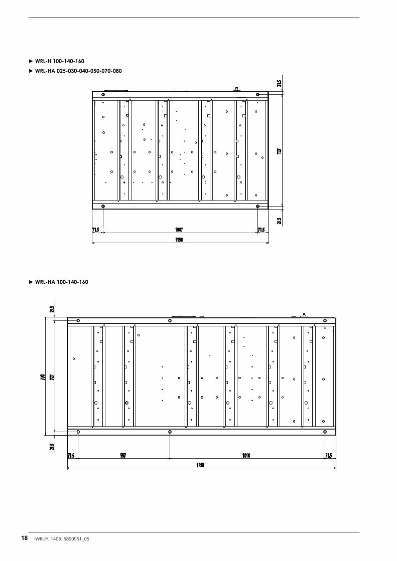
► WRL-H 100-140-160
► WRL-HA 025-030-040-050-070-080
► WRL-HA 100-140-160
18 IWRLIY. 1403. 5890961_05
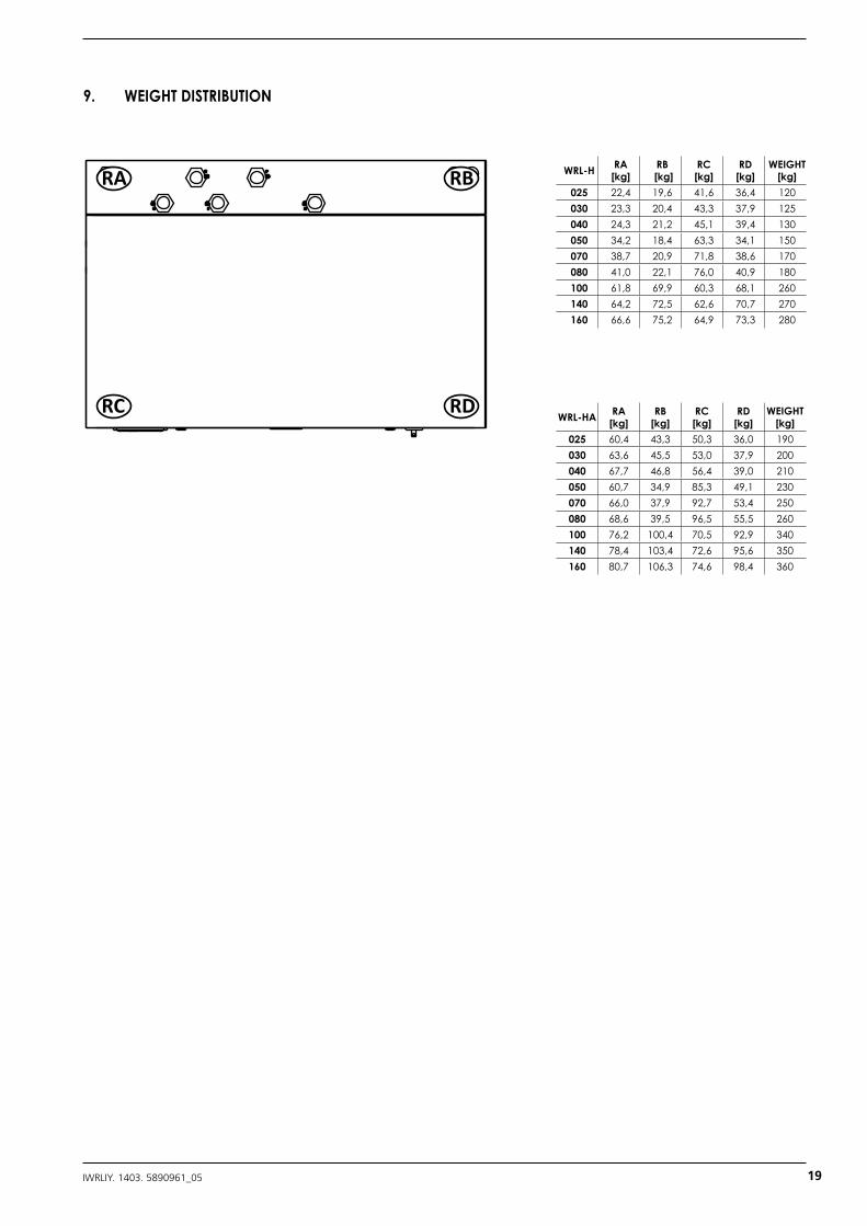
9. WEIGHT DISTRIBUTION
WRL-H RA [kg]
RB [kg]
RC [kg]
RD[kg]
WEIGHT[kg]
025 22,4 19,6 41,6 36,4 120030 23,3 20,4 43,3 37,9 125040 24,3 21,2 45,1 39,4 130050 34,2 18,4 63,3 34,1 150070 38,7 20,9 71,8 38,6 170080 41,0 22,1 76,0 40,9 180100 61,8 69,9 60,3 68,1 260140 64,2 72,5 62,6 70,7 270160 66,6 75,2 64,9 73,3 280
WRL-HA RA [kg]
RB [kg]
RC [kg]
RD [kg]
WEIGHT[kg]
025 60,4 43,3 50,3 36,0 190030 63,6 45,5 53,0 37,9 200040 67,7 46,8 56,4 39,0 210050 60,7 34,9 85,3 49,1 230070 66,0 37,9 92,7 53,4 250080 68,6 39,5 96,5 55,5 260100 76,2 100,4 70,5 92,9 340140 78,4 103,4 72,6 95,6 350160 80,7 106,3 74,6 98,4 360
RA RB
RC RD
19IWRLIY. 1403. 5890961_05
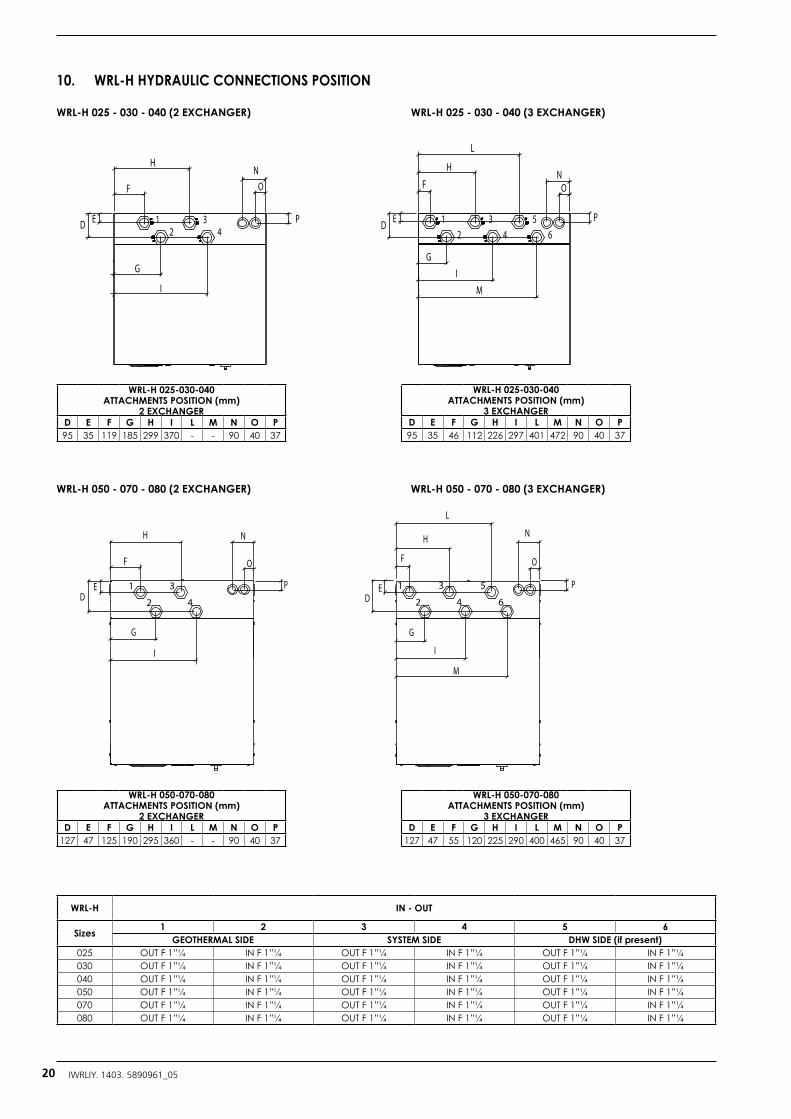
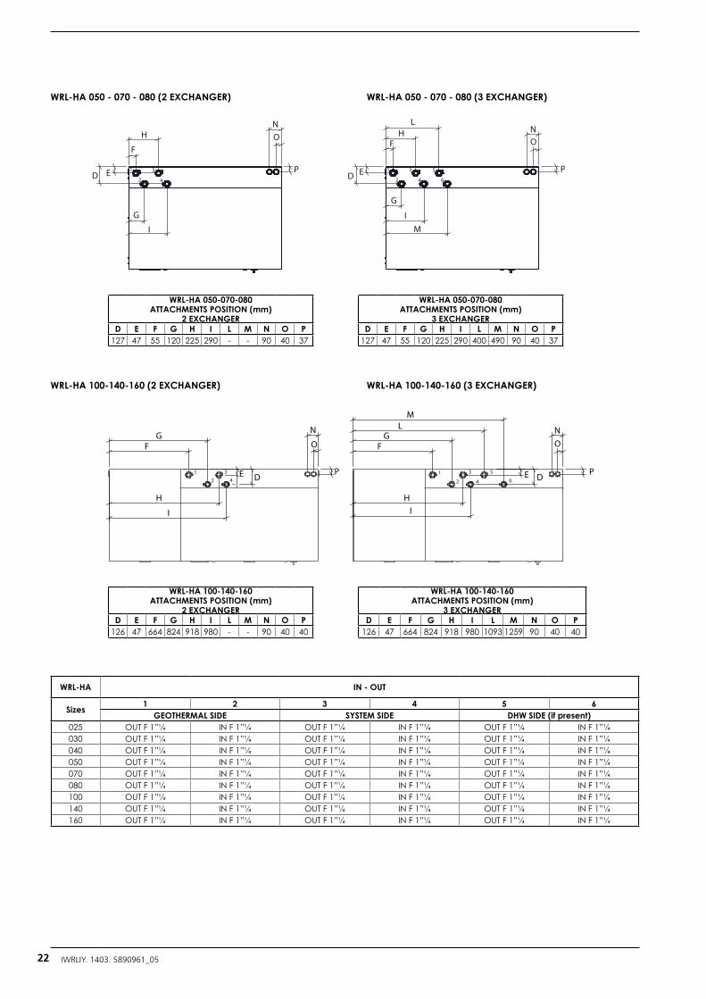
10. WRL-H HYDRAULIC CONNECTIONS POSITION
WRL-H 025-030-040 ATTACHMENTS POSITION (mm)
2 EXCHANGERD E F G H I L M N O P95 35 119 185 299 370 - - 90 40 37
WRL-H 050-070-080 ATTACHMENTS POSITION (mm)
2 EXCHANGERD E F G H I L M N O P
127 47 125 190 295 360 - - 90 40 37
WRL-H 025-030-040 ATTACHMENTS POSITION (mm)
3 EXCHANGERD E F G H I L M N O P95 35 46 112 226 297 401 472 90 40 37
WRL-H 050-070-080 ATTACHMENTS POSITION (mm)
3 EXCHANGERD E F G H I L M N O P
127 47 55 120 225 290 400 465 90 40 37
WRL-H 025 - 030 - 040 (2 EXCHANGER) WRL-H 025 - 030 - 040 (3 EXCHANGER)
1
2
3
4
5
6DE
F
G
H N
O
P
I
L
M
1
2
3
4DE
F
G
H N
O
P
I
12
34
56
D E
F
G
H
I
N
L
M
O
P1D E
F
G
H
I
NO
P2
34
WRL-H 050 - 070 - 080 (2 EXCHANGER) WRL-H 050 - 070 - 080 (3 EXCHANGER)
WRL-H IN - OUT
Sizes 1 2 3 4 5 6GEOTHERMAL SIDE SYSTEM SIDE DHW SIDE (if present)
025 OUT F 1”¼ IN F 1”¼ OUT F 1”¼ IN F 1”¼ OUT F 1”¼ IN F 1”¼030 OUT F 1”¼ IN F 1”¼ OUT F 1”¼ IN F 1”¼ OUT F 1”¼ IN F 1”¼040 OUT F 1”¼ IN F 1”¼ OUT F 1”¼ IN F 1”¼ OUT F 1”¼ IN F 1”¼050 OUT F 1”¼ IN F 1”¼ OUT F 1”¼ IN F 1”¼ OUT F 1”¼ IN F 1”¼070 OUT F 1”¼ IN F 1”¼ OUT F 1”¼ IN F 1”¼ OUT F 1”¼ IN F 1”¼080 OUT F 1”¼ IN F 1”¼ OUT F 1”¼ IN F 1”¼ OUT F 1”¼ IN F 1”¼
20 IWRLIY. 1403. 5890961_05
WRL-H IN - OUT
Sizes 1 2 3 4 5 6GEOTHERMAL SIDE SYSTEM SIDE DHW SIDE (if present)
100 OUT F 1”¼ IN F 1”¼ OUT F 1”¼ IN F 1”¼ OUT F 1”¼ IN F 1”¼140 OUT F 1”¼ IN F 1”¼ OUT F 1”¼ IN F 1”¼ OUT F 1”¼ IN F 1”¼160 OUT F 1”¼ IN F 1”¼ OUT F 1”¼ IN F 1”¼ OUT F 1”¼ IN F 1”¼
WRL-H
WRL-H 100-140-160ATTACHMENTS POSITION (mm)
2 EXCHANGER/ D E F G H I L M N O P
100 125,7 47 64 223,5 317,5 380,1 - - 90 40 40140 125,7 47 64 223,5 317,5 380,1 - - 90 40 40160 125,7 47 64 223,5 317,5 380,1 - - 90 40 40
WRL-H
WRL-H 100-140-160ATTACHMENTS POSITION (mm)
3 EXCHANGER/ D E F G H I L M N O P
100 125,7 47 64 223,5 317,5 380,1 492,5 658,6 90 40 40140 125,7 47 64 223,5 317,5 380,1 492,5 658,6 90 40 40160 125,7 47 64 223,5 317,5 380,1 492,5 658,6 90 40 40
WRL-H 100 - 140 - 160 (2 EXCHANGER) WRL-H 100 - 140 - 160 (3 EXCHANGER)
DE
FG
H
1
2
3 564
LM
N
P
O
I
DE
FG
H
1
2
34
N
P
O
I
ED
F
H
GI
N
O
P P
O
N
FH
L
D E
G
IM
2
1 3
4 42 6
531
ED
F
H
G
I
NO
P P
ON
FH
L
ED
G
IM
2
1 3
4 42 6
531
42
31 1
2
3
4
5
6
O
N
FG
H
I
P
ON
FG
HI
LM
PE D E D
WRL-HA 025-030-040 ATTACHMENTS POSITION (mm)
2 EXCHANGERD E F G H I L M N O P
127 47 55 120 225 290 - - 90 40 37
WRL-HA 025-030-040 ATTACHMENTS POSITION (mm)
3 EXCHANGERD E F G H I L M N O P
127 47 55 120 225 290 400 490 90 40 37
11. WRL-HA HYDRAULIC CONNECTIONS POSITION
WRL-HA 025 - 030 - 040 (2 EXCHANGER) WRL-HA 025 - 030 - 040 (3 EXCHANGER)
21IWRLIY. 1403. 5890961_05
ED
F
H
GI
N
O
P P
O
N
FH
L
D E
G
IM
2
1 3
4 42 6
531
ED
F
H
G
I
NO
P P
ON
FH
L
ED
G
IM
2
1 3
4 42 6
531
42
31 1
2
3
4
5
6
O
N
FG
H
I
P
ON
FG
HI
LM
PE D E D
ED
F
H
GI
N
O
P P
O
N
FH
L
D E
G
IM
2
1 3
4 42 6
531
ED
F
H
G
I
NO
P P
ON
FH
L
ED
G
IM
2
1 3
4 42 6
531
42
31 1
2
3
4
5
6
O
N
FG
H
I
P
ON
FG
HI
LM
PE D E D
WRL-HA 050-070-080 ATTACHMENTS POSITION (mm)
2 EXCHANGERD E F G H I L M N O P
127 47 55 120 225 290 - - 90 40 37
WRL-HA 100-140-160 ATTACHMENTS POSITION (mm)
2 EXCHANGERD E F G H I L M N O P
126 47 664 824 918 980 - - 90 40 40
WRL-HA 050-070-080 ATTACHMENTS POSITION (mm)
3 EXCHANGERD E F G H I L M N O P
127 47 55 120 225 290 400 490 90 40 37
WRL-HA 100-140-160 ATTACHMENTS POSITION (mm)
3 EXCHANGERD E F G H I L M N O P
126 47 664 824 918 980 1093 1259 90 40 40
WRL-HA 050 - 070 - 080 (2 EXCHANGER)
WRL-HA 100-140-160 (2 EXCHANGER)
WRL-HA 050 - 070 - 080 (3 EXCHANGER)
WRL-HA 100-140-160 (3 EXCHANGER)
WRL-HA IN - OUT
Sizes 1 2 3 4 5 6GEOTHERMAL SIDE SYSTEM SIDE DHW SIDE (if present)
025 OUT F 1”¼ IN F 1”¼ OUT F 1”¼ IN F 1”¼ OUT F 1”¼ IN F 1”¼030 OUT F 1”¼ IN F 1”¼ OUT F 1”¼ IN F 1”¼ OUT F 1”¼ IN F 1”¼040 OUT F 1”¼ IN F 1”¼ OUT F 1”¼ IN F 1”¼ OUT F 1”¼ IN F 1”¼050 OUT F 1”¼ IN F 1”¼ OUT F 1”¼ IN F 1”¼ OUT F 1”¼ IN F 1”¼070 OUT F 1”¼ IN F 1”¼ OUT F 1”¼ IN F 1”¼ OUT F 1”¼ IN F 1”¼080 OUT F 1”¼ IN F 1”¼ OUT F 1”¼ IN F 1”¼ OUT F 1”¼ IN F 1”¼100 OUT F 1”¼ IN F 1”¼ OUT F 1”¼ IN F 1”¼ OUT F 1”¼ IN F 1”¼140 OUT F 1”¼ IN F 1”¼ OUT F 1”¼ IN F 1”¼ OUT F 1”¼ IN F 1”¼160 OUT F 1”¼ IN F 1”¼ OUT F 1”¼ IN F 1”¼ OUT F 1”¼ IN F 1”¼
22 IWRLIY. 1403. 5890961_05
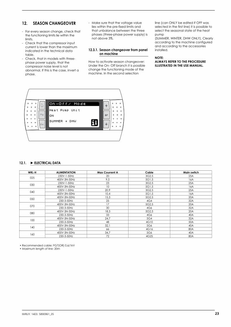
On-Off/ Mode
Heat Pump Unit
SUMMER + DHW
ON
12. SEASON CHANGEOVER
- For every season change, check that the functioning limits lie within the limits.
- Check that the compressor input current is lower than the maximum indicated in the technical data table.
- Check, that in models with three-phase power supply, that the compressor noise level is not abnormal. If this is the case, invert a phase.
- Make sure that the voltage value lies within the pre-fixed limits and that unbalance between the three phases (three-phase power supply) is not above 3%.
12.3.1. Season changeover from panel on machine
How to activate season changeover:Under the On- Off branch it is possible change the functioning mode of the machine. In the second selection
line (can ONLY be edited if OFF was selected in the first line) it is possible to select the seasonal state of the heat pump(SUMMER, WINTER, DHW ONLY). Clearly according to the machine configured and according to the accessories installed.
NOTE:ALWAYS REFER TO THE PROCEDURE ILLUSTRATED IN THE USE MANUAL.
WRL-H ALIMENTATION Max Courrent A Cable Main switch
025 230V-1-50Hz 20 3G2,5 25A400V-3N-50Hz 9,5 5G1,5 16A
030 230V-1-50Hz 23 3G2,5 25A400V-3N-50Hz 10 5G1,5 16A
040 230V-1-50Hz 20,9 3G2,5 25A400V-3N-50Hz 10,4 5G1,5 16A
050 400V-3N-50Hz 15,3 5G2,5 20A230-3-50Hz 25 4G4 32A
070 400V-3N-50Hz 17 5G2,5 20A230-3-50Hz 30 4G6 32A
080 400V-3N-50Hz 18,3 5G2,5 20A230-3-50Hz 33 4G6 40A
100 400V-3N-50Hz 24,7 5G4 32A230-3-50Hz 48 4G10 50A
140 400V-3N-50Hz 32,1 5G6 40A230-3-50Hz 66 4G16 80A
160 400V-3N-50Hz 34,7 5G6 40A230-3-50Hz 72 4G25 80A
• Recommended cable: FG7(OR) 0,6/1kV• Maximum length of line: 20m
23IWRLIY. 1403. 5890961_05
12.1. ► ELECTRICAL DATA
13. WIRING DIAGRAM
C4
NO8
NO9
NO10
NO11
NO12
RX-/TX-RX+/TX+GND
Vout
C1
NO1
NO2
NO3
C2
NO4
NO5
NO6
NO7
C3
NC7
G
G0
B1
B2
B3B4
B5
B6B7
GND
+Vdc
+Vdc
GND
+5 Vref
GND
Y1
Y2
Y3
Y4
DI1
DI2
DI3
DI4
DI5
DI6
DI7
DIC1
B8B9
B10
B11
B12
GND
ID8
ID9
ID10
IDC2
J2 - probe supply
J3 - analog input
J4 - digital input
J5 - analog output
J18 - analog input
J17 - valve 2
J16 - digital input
J6
J7
J8
J9
J10
J11
J12 - group 1
J13 - group 1
J14 - group 2
J15 - group 3
J1 - power supply
RX-/TX-RX+/TX+GND
11.D
I10
11.D
I9
11.D
I8
11.B
12
11.B
11
+5VA
EF+5
VAEF
+5VA
EF+5
VAEF
11.B
10
11.B
9
11.B
8
10.Y
4
10.Y
3
10.Y
1
10.D
I7
10.D
I6
10.D
I5
10.D
I3
10.D
I1
9.B
7
9.B
6
9.B
5
9.B
4
9.B
3
9.B
2
9.B
1
10.T
2
GN
DX2
GN
D
GN
D
GN
D
GN
D
GN
D
GN
D
GN
D
GN
D
GN
D
GN
D
GN
D
GN
D
GN
D
GN
DG
ND
GN
D
GN
D
GN
D
GN
D
GN
D
GN
D
GN
D
GN
D
GN
D
GN
D
GN
D
GN
D
GN
D
GN
D
GN
D
GN
D
GN
D
GN
D
GN
D
GN
D
GN
D
GN
D
GN
D
GN
D
GN
D
GN
D
GN
D
GN
D
GN
D
GN
D
GN
D
GN
D
GN
D
GN
D
GN
D
GN
D
11.D
I10
11.D
I9
11.D
I8
11.B
12
11.B
11
11.B
10
11.B
9
11.B
8
10.Y
4
10.Y
3
10.Y
1
10.D
I7
10.D
I6
10.D
I5
10.D
I3
10.D
I1
9.B
7
9.B
6
9.B
5
9.B
4
9.B
3
9.B
2
9.B
1
10.T
2
GN
D
T+ T-
GN
D
T+ T-
GN
D
Tx+ T x-
230V
50Hz
CA
RE
L D
ara 06 N
S:N
. A001
RO
HS
ATA
C
ode ATA
G
ND
Tx+ T x -
230V
50Hz
CA
RE
L D
ara 06 N
S:N
. A001
RO
HS
ATA
C
ode ATA
GN
D
Tx+ T x-
230V
50Hz
CA
RE
L D
ara 06 N
S:N
. A001
RO
HS
ATA
C
ode ATA
GN
D
Tx+ Tx-
230V
50Hz
CA
RE
L D
ara 06 N
S:N
. A001
RO
HS
ATA
C
ode ATA
GN
D
Tx+ Tx-
230V
50Hz
CA
RE
L D
ara 06 N
S:N
. A001
RO
HS
ATA
C
ode ATA
ON 1 2 3 4 ON 1 2 3 4
Zona 2 Zona 3
Zona 1
Addr 1
Addr 2
Addr 4
Addr 5
Addr 3
Zona 2
Zona 2 Zona 3 Zona 3
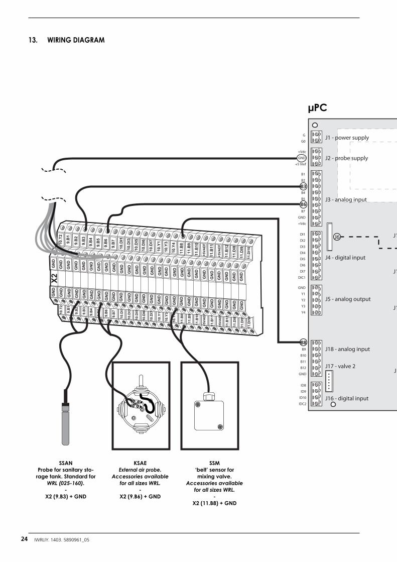
SSANProbe for sanitary sto-
rage tank. Standard for WRL (025-160).
-X2 (9.B3) + GND
µPC
KSAEExternal air probe.
Accessories available for all sizes WRL.
-X2 (9.B6) + GND
SSM‘belt’ sensor for mixing valve.
Accessories available for all sizes WRL.
-X2 (11.B8) + GND
24 IWRLIY. 1403. 5890961_05
C4
NO8
NO9
NO10
NO11
NO12
RX-/TX-RX+/TX+GND
Vout
C1
NO1
NO2
NO3
C2
NO4
NO5
NO6
NO7
C3
NC7
G
G0
B1
B2
B3B4
B5
B6B7
GND
+Vdc
+Vdc
GND
+5 Vref
GND
Y1
Y2
Y3
Y4
DI1
DI2
DI3
DI4
DI5
DI6
DI7
DIC1
B8B9
B10
B11
B12
GND
ID8
ID9
ID10
IDC2
J2 - probe supply
J3 - analog input
J4 - digital input
J5 - analog output
J18 - analog input
J17 - valve 2
J16 - digital input
J6
J7
J8
J9
J10
J11
J12 - group 1
J13 - group 1
J14 - group 2
J15 - group 3
J1 - power supply
RX-/TX-RX+/TX+GND
11.D
I10
11.D
I9
11.D
I8
11.B
12
11.B
11
+5VA
EF+5
VAEF
+5VA
EF+5
VAEF
11.B
10
11.B
9
11.B
8
10.Y
4
10.Y
3
10.Y
1
10.D
I7
10.D
I6
10.D
I5
10.D
I3
10.D
I1
9.B
7
9.B
6
9.B
5
9.B
4
9.B
3
9.B
2
9.B
1
10.T
2
GN
DX2
GN
D
GN
D
GN
D
GN
D
GN
D
GN
D
GN
D
GN
D
GN
D
GN
D
GN
D
GN
D
GN
D
GN
DG
ND
GN
D
GN
D
GN
D
GN
D
GN
D
GN
D
GN
D
GN
D
GN
D
GN
D
GN
D
GN
D
GN
D
GN
D
GN
D
GN
D
GN
D
GN
D
GN
D
GN
D
GN
D
GN
D
GN
D
GN
D
GN
D
GN
D
GN
D
GN
D
GN
D
GN
D
GN
D
GN
D
GN
D
GN
D
GN
D
GN
D
11.D
I10
11.D
I9
11.D
I8
11.B
12
11.B
11
11.B
10
11.B
9
11.B
8
10.Y
4
10.Y
3
10.Y
1
10.D
I7
10.D
I6
10.D
I5
10.D
I3
10.D
I1
9.B
7
9.B
6
9.B
5
9.B
4
9.B
3
9.B
2
9.B
1
10.T
2
GN
D
T+ T-
GN
D
T+ T-
GN
D
Tx+ T x-
230V
50Hz
CA
RE
L D
ara 06 N
S:N
. A001
RO
HS
ATA
C
ode ATA
G
ND
Tx+ T x -
230V
50Hz
CA
RE
L D
ara 06 N
S:N
. A001
RO
HS
ATA
C
ode ATA
GN
D
Tx+ T x-
230V
50Hz
CA
RE
L D
ara 06 N
S:N
. A001
RO
HS
ATA
C
ode ATA
GN
D
Tx+ Tx-
230V
50Hz
CA
RE
L D
ara 06 N
S:N
. A001
RO
HS
ATA
C
ode ATA
GN
D
Tx+ Tx-
230V
50Hz
CA
RE
L D
ara 06 N
S:N
. A001
RO
HS
ATA
C
ode ATA
ON 1 2 3 4 ON 1 2 3 4
Zona 2 Zona 3
Zona 1
Addr 1
Addr 2
Addr 4
Addr 5
Addr 3
Zona 2
Zona 2 Zona 3 Zona 3
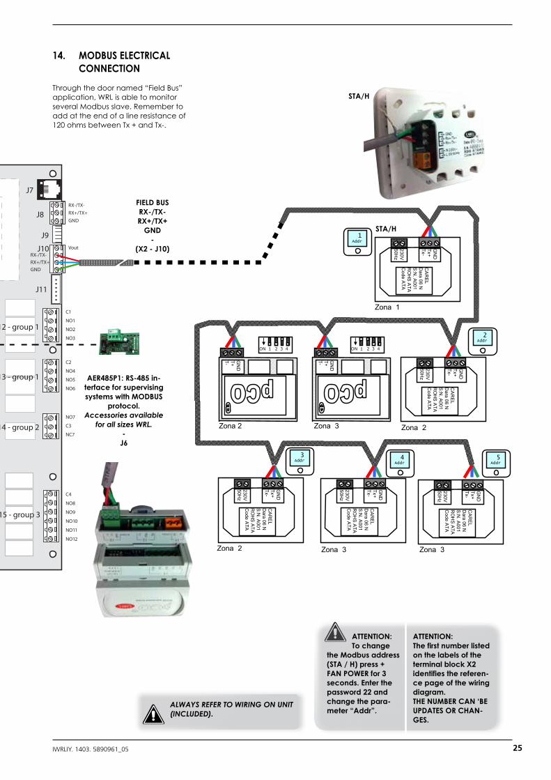
14. MODBUS ELECTRICAL CONNECTION
Through the door named “Field Bus” application, WRL is able to monitor several Modbus slave. Remember to add at the end of a line resistance of 120 ohms between Tx + and Tx-.
AER485P1: RS-485 in-terface for supervising systems with MODBUS
protocol. Accessories available
for all sizes WRL.-
J6
FIELD BUS RX-/TX-RX+/TX+
GND-
(X2 - J10)
STA/H
STA/H
ATTENTION:To change
the Modbus address (STA / H) press + FAN POWER for 3 seconds. Enter the password 22 and change the para-meter “Addr”.
ATTENTION:The first number listed on the labels of the terminal block X2 identifies the referen-ce page of the wiring diagram.THE NUMBER CAN ‘BE UPDATES OR CHAN-GES.
ALWAYS REFER TO WIRING ON UNIT (INCLUDED).
25IWRLIY. 1403. 5890961_05
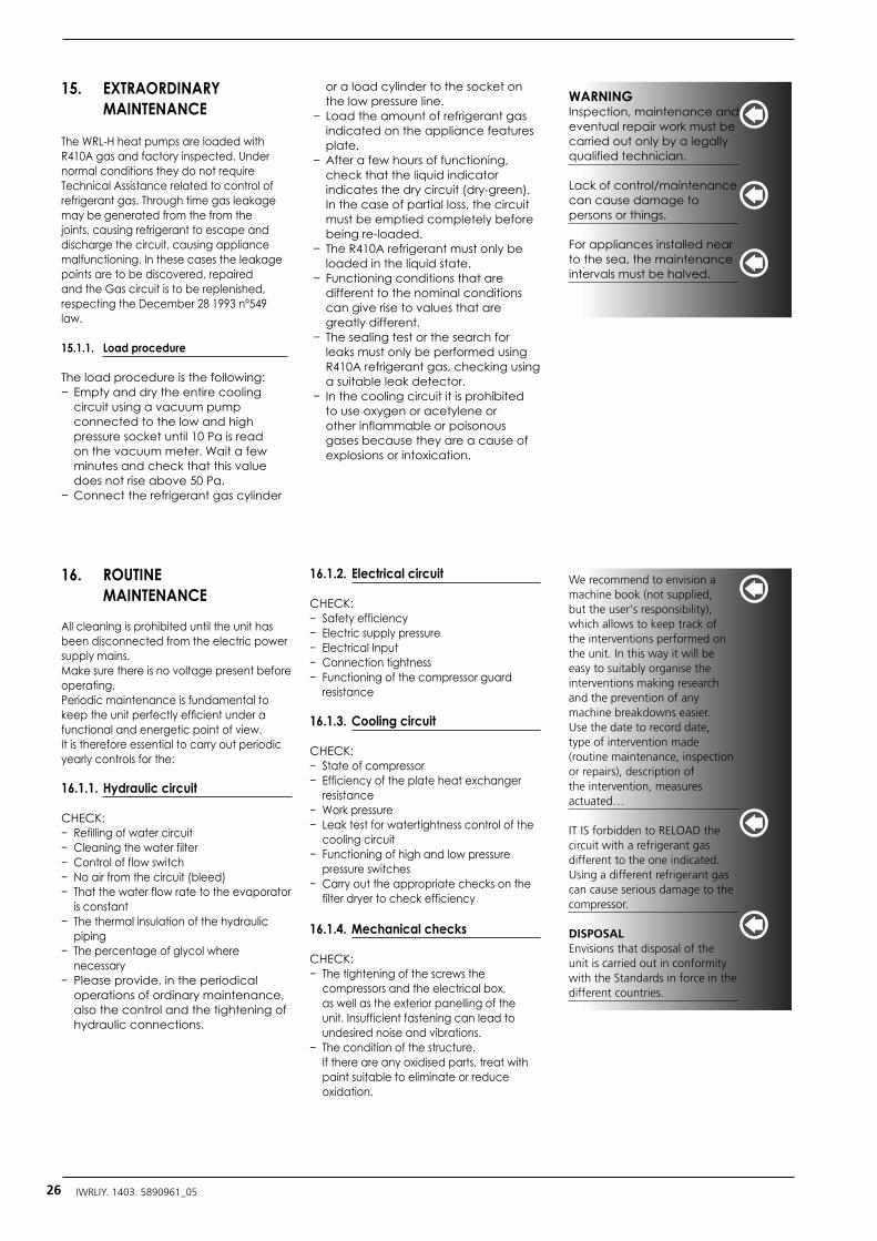
15. EXTRAORDINARY MAINTENANCE
The WRL-H heat pumps are loaded with R410A gas and factory inspected. Under normal conditions they do not require Technical Assistance related to control of refrigerant gas. Through time gas leakage may be generated from the from the joints, causing refrigerant to escape and discharge the circuit, causing appliance malfunctioning. In these cases the leakage points are to be discovered, repaired and the Gas circuit is to be replenished, respecting the December 28 1993 n°549 law.
15.1.1. Load procedure
The load procedure is the following:− Empty and dry the entire cooling
circuit using a vacuum pump connected to the low and high pressure socket until 10 Pa is read on the vacuum meter. Wait a few minutes and check that this value does not rise above 50 Pa.
− Connect the refrigerant gas cylinder
or a load cylinder to the socket on the low pressure line.
− Load the amount of refrigerant gas indicated on the appliance features plate.
− After a few hours of functioning, check that the liquid indicator indicates the dry circuit (dry-green). In the case of partial loss, the circuit must be emptied completely before being re-loaded.
− The R410A refrigerant must only be loaded in the liquid state.
− Functioning conditions that are different to the nominal conditions can give rise to values that are greatly different.
− The sealing test or the search for leaks must only be performed using R410A refrigerant gas, checking using a suitable leak detector.
− In the cooling circuit it is prohibited to use oxygen or acetylene or other inflammable or poisonous gases because they are a cause of explosions or intoxication.
WARNINGInspection, maintenance and eventual repair work must be carried out only by a legally qualified technician.
Lack of control/maintenance can cause damage to persons or things.
For appliances installed near to the sea, the maintenance intervals must be halved.
16. ROUTINE MAINTENANCE
All cleaning is prohibited until the unit has been disconnected from the electric power supply mains.Make sure there is no voltage present before operating.Periodic maintenance is fundamental to keep the unit perfectly efficient under a functional and energetic point of view. It is therefore essential to carry out periodic yearly controls for the:
16.1.1. Hydraulic circuit
CHECK:− Refilling of water circuit− Cleaning the water filter − Control of flow switch− No air from the circuit (bleed)− That the water flow rate to the evaporator
is constant− The thermal insulation of the hydraulic
piping− The percentage of glycol where
necessary− Please provide, in the periodical
operations of ordinary maintenance, also the control and the tightening of hydraulic connections.
16.1.2. Electrical circuit
CHECK:− Safety efficiency− Electric supply pressure − Electrical Input− Connection tightness− Functioning of the compressor guard
resistance
16.1.3. Cooling circuit
CHECK:− State of compressor− Efficiency of the plate heat exchanger
resistance − Work pressure− Leak test for watertightness control of the
cooling circuit− Functioning of high and low pressure
pressure switches − Carry out the appropriate checks on the
filter dryer to check efficiency
16.1.4. Mechanical checks
CHECK:− The tightening of the screws the
compressors and the electrical box, as well as the exterior panelling of the unit. Insufficient fastening can lead to undesired noise and vibrations.
− The condition of the structure. If there are any oxidised parts, treat with paint suitable to eliminate or reduce oxidation.
We recommend to envision a machine book (not supplied, but the user's responsibility), which allows to keep track of the interventions performed on the unit. In this way it will be easy to suitably organise the interventions making research and the prevention of any machine breakdowns easier. Use the date to record date, type of intervention made (routine maintenance, inspection or repairs), description of the intervention, measures actuated…
IT IS forbidden to RELOAD the circuit with a refrigerant gas different to the one indicated. Using a different refrigerant gas can cause serious damage to the compressor.
DISPOSAL Envisions that disposal of the unit is carried out in conformity with the Standards in force in the different countries.
26 IWRLIY. 1403. 5890961_05
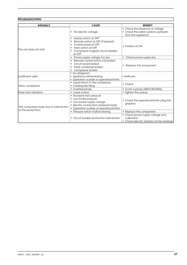
TROUBLESHOOTING
ANOMALY CAUSE REMEDY
The unit does not start
• No electric voltage• Check the presence of voltage• Check the safety systems upstream
from the appliance• Master switch at OFF• Remote switch at OFF (if present)• Control panel at OFF• Main switch at OFF• Compressor magnet circuit breaker
at OFF
• Position at ON
• Power supply voltage too low • Check power supply line• Remote control switch coil broken• Circuit board broken• Peak condenser broken• Compressor broken
• Replace the component
Insufficient yield• No refrigerant• Appliance dimensioning• Operation outside of operational limits
▪ Verificare
Noisy compressor• Liquid return to the compressor• Inadequate fixing • Check
• Inverted phase • Invert a phase (400V/3N/50Hz)Noise and vibrations • Loose screws • Tighten the screws
The compressor stops due to intervention of the protections
• Excessive flow pressure• Low intake pressure• Low power supply voltage• Electric connections fastened badly• Operation outside of operational limits
• Check the operational limits using the graphics
• Pressure switch malfunctioning • Replace the component
• Circuit breaker protection intervention• Check power supply voltage and
calibration• Check electric isolation of the windings
27IWRLIY. 1403. 5890961_05

37040 Bevilacqua (VR) - ItalyVia Roma, 996 - Tel. (+39) 0442 633111Telefax (+39) 0442 93730 - (+39) 0442 93566www.aermec.com The technical data given on the following documentation are not
binding. Aermec reserves the right to apply at any time all the modifications deemed necessary for improving the product.
carta riciclatarecycled paperpapier recyclérecycled Papier
carta reciclata recycled paperpapier recyclérecycled papier