Embed Size (px)
Citation preview
The Southern African Institute of Mining and Metallurgy
Sulphur and Sulphuric Acid Conference 2009
Matthew D. Viergutz
Page 79
HEAT RECOVERY SYSTEM UPDATE
Matthew D. Viergutz
MECS, Inc.
Abstract
MECS’ HRS technology has reliably recovered intermediate pressure steam from sulphuric
acid plants for more than 20 years. This steam can either generate electricity or replace steam
produced by an existing fuel-fired boiler. As worldwide greenhouse gas emissions continue
to rise, industries are looking for novel and cost effective solutions to reduce pollution,
particularly carbon dioxide, from their plants. Waste heat recovery technologies such as HRS
offer new and existing plants the opportunity to maximize energy efficiency while reducing
their reliance on energy supply from external sources. This paper offers a unique look at
energy recovery in sulphuric acid plants and how recent innovations in MECS’ Heat
Recovery System technology make HRS more financially viable – and more green - than
ever.
Heat Recovery System Background
Over the past few decades, energy recovery in sulphuric acid plants, like the contact process
itself, has stabilized around a few key design features. Most companies require the recovery
of as much process heat as possible to produce high pressure steam, which can be used to
produce power or run other turbines in the plant. The development of low temperature
economizers in the 1980s caused sulphuric acid plant energy efficiency to peak. With
approximately 70% of available heat converted into high pressure steam, and with the
remaining 30% lost to the atmosphere or to cooling water in the strong acid system, the
industry seemed to have reached maximum energy efficiency.
The development of MECS’s Heat Recovery System (HRS) in the 1980s shifted the energy
recovery paradigm of the sulphuric acid industry. HRS increased the thermal efficiency of an
acid plant to greater than 90%, and the steam recovered in an HRS could be: (i) used to
produce power; (ii) used as process heat within the site; or (iii) sold to an external customer.
MECS commercialized nineteen HRS during the 1990s, all but one of which are operating
today. Low fertilizer, metal, and energy prices reduced demand for HRS in the early 2000s,
but the technology has seen a revitalization in the past few years due to high steam values and
a long track record of HRS reliability around the world. Companies in markets as diverse as
the United States, Morocco, Lithuania, and China are using HRS as a reliable way to increase
the energy efficiency of their plants without sacrificing on-stream time or maintenance.
Heat Recovery System Design
The HRS functions simultaneously as an interpass absorbing system and as a generator of
intermediate pressure steam. The HRS, consisting of a high temperature absorbing tower,
boiler, heater, and diluter, recovers heat evolved in the interpass tower circulating system in
the form of intermediate pressure (typically 3 to 10 barg) steam. A steam injection vessel and
preheater are provided as options for additional heat recovery.
The Southern African Institute of Mining and Metallurgy
Sulphur and Sulphuric Acid Conference 2009
Matthew D. Viergutz
Page 80
Table 1 below illustrates the increase in overall heat recovery of a sulphur burning plant with
HRS when compared to a conventional sulphur burning plant.
Conventional Conventional Plant
With HRS
HRS w/ Steam
Injection
HP Steam ton/ton 1.27 1.201 1.19
IP Steam ton/ton 0 0.40 0.48
Heat Recovered 70% 93% 94%
Net Power
kW/MTPD
10.6 14.6 14.8
Table 1: Energy Recovery in a Sulphuric Acid Plant
HRS Operation
HRS has achieved commercial success by consistently providing customers with a reliable
source of intermediate pressure steam. MECS uses the following principles to design for
long equipment life and high on-stream time:
1) Increase the acid temperature in the interpass circuit above the boiling point of 3-10
barg steam.
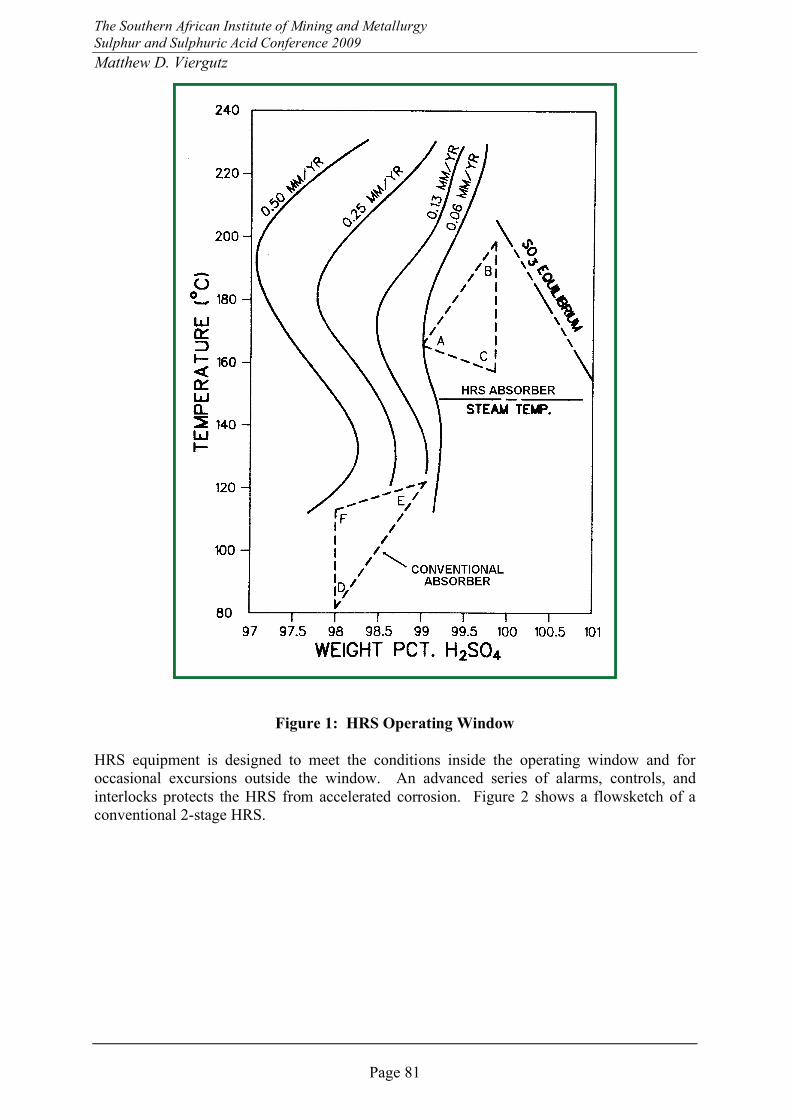
2) Control the acid concentration within an optimum window (refer to Figure 1 for a
comparison of the HRS operating window to the interpass system operating window).
3) Match system components with materials of construction that exhibit low levels of
corrosion in the operating window and during upset conditions.
1 Steam production figures shown in Table 1 are for a new sulphuric acid plant designed to maximize power
production. Adding an HRS to an existing plant will not reduce steam flow from the high pressure steam
system.
The Southern African Institute of Mining and Metallurgy
Sulphur and Sulphuric Acid Conference 2009
Matthew D. Viergutz
Page 81
Figure 1: HRS Operating Window
HRS equipment is designed to meet the conditions inside the operating window and for
occasional excursions outside the window. An advanced series of alarms, controls, and
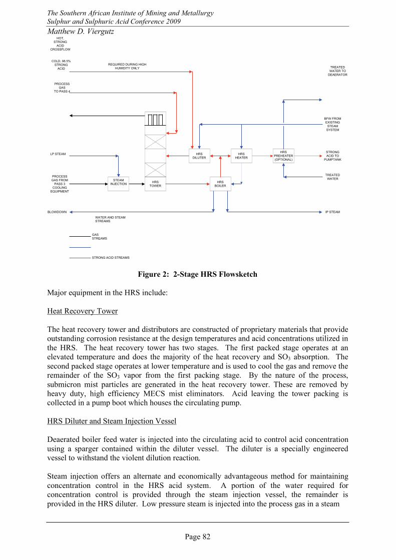
interlocks protects the HRS from accelerated corrosion. Figure 2 shows a flowsketch of a
conventional 2-stage HRS.
The Southern African Institute of Mining and Metallurgy
Sulphur and Sulphuric Acid Conference 2009
Matthew D. Viergutz
Page 82
HRS
HEATER
HRS
DILUTER
HRS
BOILER
HRS
PREHEATER
(OPTIONAL)
STRONG
ACID TO
PUMPTANK
BLOWDOWN IP STEAM
TREATED
WATERPROCESS
GAS FROM
PASS 3
COOLING
EQUIPMENT
PROCESS
GAS
TO PASS 4
COLD, 98.5%
STRONG
ACID
HOT,
STRONG
ACID
CROSSFLOW
STEAM
INJECTION
LP STEAM
REQUIRED DURING HIGH
HUMIDITY ONLY
BFW FROM
EXISTING
STEAM
SYSTEM
GAS
STREAMS
WATER AND STEAM
STREAMS
STRONG ACID STREAMS
TREATED
WATER TO
DEAERATOR
HRS
TOWER
Figure 2: 2-Stage HRS Flowsketch
Major equipment in the HRS include:
Heat Recovery Tower
The heat recovery tower and distributors are constructed of proprietary materials that provide
outstanding corrosion resistance at the design temperatures and acid concentrations utilized in
the HRS. The heat recovery tower has two stages. The first packed stage operates at an
elevated temperature and does the majority of the heat recovery and SO3 absorption. The
second packed stage operates at lower temperature and is used to cool the gas and remove the
remainder of the SO3 vapor from the first packing stage. By the nature of the process,
submicron mist particles are generated in the heat recovery tower. These are removed by
heavy duty, high efficiency MECS mist eliminators. Acid leaving the tower packing is
collected in a pump boot which houses the circulating pump.
HRS Diluter and Steam Injection Vessel
Deaerated boiler feed water is injected into the circulating acid to control acid concentration
using a sparger contained within the diluter vessel. The diluter is a specially engineered
vessel to withstand the violent dilution reaction.
Steam injection offers an alternate and economically advantageous method for maintaining
concentration control in the HRS acid system. A portion of the water required for
concentration control is provided through the steam injection vessel, the remainder is
provided in the HRS diluter. Low pressure steam is injected into the process gas in a steam
The Southern African Institute of Mining and Metallurgy
Sulphur and Sulphuric Acid Conference 2009
Matthew D. Viergutz
Page 83
injection chamber upstream of the heat recovery tower. Latent heat from condensation also
boosts generation of medium pressure steam as compared to HRS without steam injection.
Water that is added in the form of steam rather than liquid water reduces the size of the
diluter, reduces the size of the HRS tower and distributors, and decreases the acid flow into
the HRS tower. Steam injection also upgrades low pressure steam that may otherwise be
vented to atmosphere.
HRS boiler, heater and preheater
The boiler removes heat from the acid circulating in the HRS circuit by producing medium
pressure steam. Acid produced in the HRS is further cooled by the heater followed by the
preheater before being transferred to the main acid system. The heater heats boiler feed water
to the HRS boiler. The preheater typically heats treated water to the acid plant deaerator. If
the HRS preheater were not used, hot acid from the outlet of the HRS heater would be
returned to the strong acid system, and energy would be lost to the acid plant cooling water
system. The preheater offers a means to transfer this additional duty to a more useful source.
HRS Improvements
MECS continues to focus on improvements that make HRS more attractive to existing plants.
The first and most straight forward retrofit is a complete interpass absorbing system
replacement with an HRS. Gas ducts and strong acid piping are rerouted to the new HRS
tower and heat exchangers.
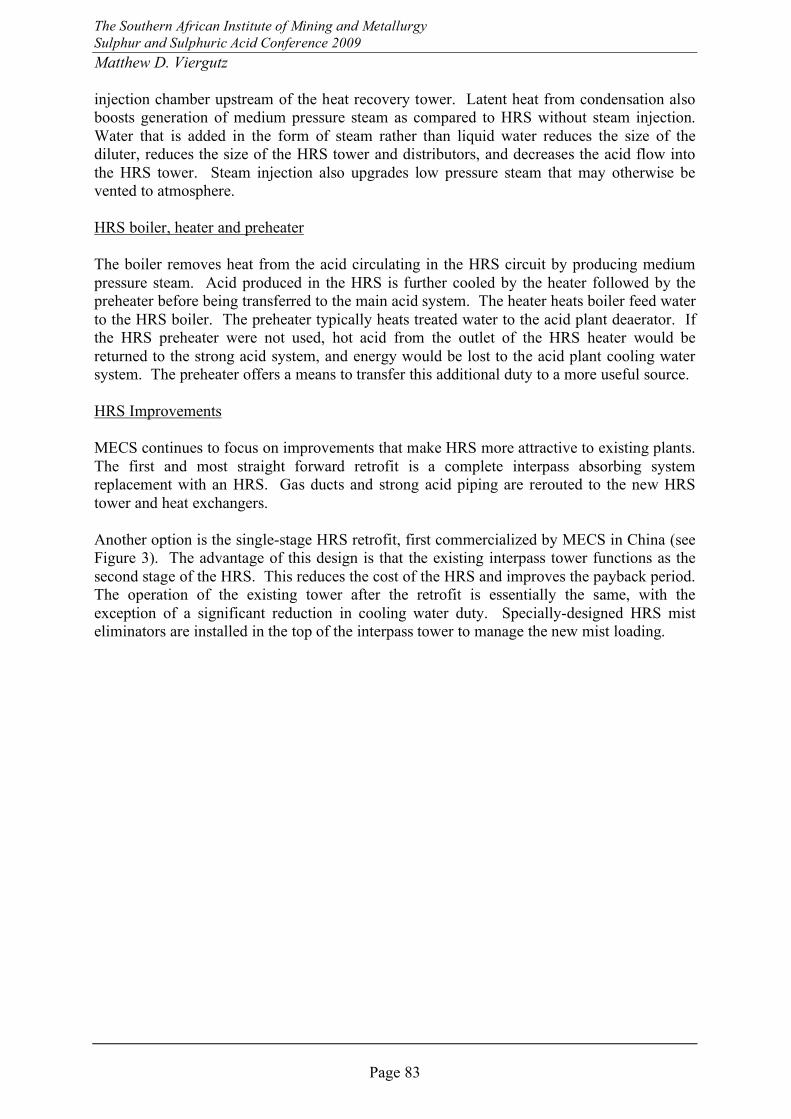
Another option is the single-stage HRS retrofit, first commercialized by MECS in China (see
Figure 3). The advantage of this design is that the existing interpass tower functions as the
second stage of the HRS. This reduces the cost of the HRS and improves the payback period.
The operation of the existing tower after the retrofit is essentially the same, with the
exception of a significant reduction in cooling water duty. Specially-designed HRS mist
eliminators are installed in the top of the interpass tower to manage the new mist loading.
The Southern African Institute of Mining and Metallurgy
Sulphur and Sulphuric Acid Conference 2009
Matthew D. Viergutz
Page 84
HRS
HEATER
HRS
DILUTER
HRS
BOILER
STRONG ACID
TO COMMON
PUMPTANK
BLOWDOWN
IP STEAM
PROCESS GAS
FROM
ECONOMIZER 3B
PROCESS GAS
TO COLD
INTERPASS
HEX
STRONG ACID
FROM
INTERPASS
TOWER PUMP
REQUIRED DURING HIGH HUMIDITY ONLY
BFW FROM
EXISTING
STEAM
SYSTEM
STRONG ACID
FROM
INTERPASS
TOWER
COOLERS
STRONG ACID
TO COMMON
PUMPTANK
EXISTING
INTERPASS
TOWER
(EXISTING)
HRS
TOWER
HRS MIST
ELIMINATORS
GAS STREAMS
WATER AND STEAM STREAMS
STRONG ACID STREAMS
STEAM
INJECTION
(OPTIONAL)
LP STEAM
(OPTIONAL)
Figure 3: Single-Stage HRS Retrofit
HRS Retrofit Case Study
Ten years ago when a Metallurgical Double Absorption Sulphuric Acid Plant was
constructed, the economics of the HRS process were not viable. However, the client did
recognize that an HRS may be profitable in the future and the new interpass absorbing tower
purchased for the plant was designed for future use as an HRS tower and made of ZeCor®–
310M. This client studied the economic impact of adding an HRS again when a recent
MECS debottlenecking project increased the plant capacity to 2720 MTPD, but they could
not find economic merit with producing steam for a turbogenerator and selling the power.
However, with the high oil prices, this client recently found a nearby company that was
interested in purchasing medium pressure steam at a price that was highly profitable. The
sulphuric acid plant was retrofit with MECS’ standard HRS equipment including an HRS
boiler, diluter, steam injection vessel, heater, and preheater. The interpass absorbing tower
was converted to an HRS tower with the addition of a 2nd stage UniFLOTM
Distributor, 2nd
stage packing, and an HRS pump boot. Because HRS towers have more mist generation than
interpass absorbing towers, new mist eliminator elements were necessary for the HRS retrofit
project. Custom-designed concentric Energy Saver (ES) mist eliminator elements replaced
the existing ES elements, thus increasing the element surface area without increasing the mist
eliminator housing diameter or changing the tubesheet. This client is now realizing the
economic benefits from generating 10 barg HRS steam.
Conclusion
MECS’s recent development of the single-stage HRS retrofit reduces the investment cost
required to recover heat generated in a sulphuric acid plant’s acid system. Decreasing
payback periods, high on-stream time, and a worldwide push for green sources of energy
make HRS more attractive than ever.
The Southern African Institute of Mining and Metallurgy
Sulphur and Sulphuric Acid Conference 2009
Matthew D. Viergutz
Page 85
The Author
Matthew D. Viergutz, Global Sulphuric Marketing Leader, MECS, Inc.
Matthew Viergutz started with MECS in 1998 as a Process Engineer and led the design of a
major sulphur burning upgrade in Europe. He also designed a spent acid regeneration unit for
a refinery in Asia. In 2001 he joined the MECS marketing team where he currently leads a
team of engineers that support global sales and marketing of MECS technology with an
emphasis on the Asia-Pacific region.

The Southern African Institute of Mining and Metallurgy
Sulphur and Sulphuric Acid Conference 2009
Matthew D. Viergutz
Page 86