Embed Size (px)
Citation preview

www.kaeser.com
Heat Recovery Systems PTG / SWT Series
www.kaeser.com
2 3
Approx. 5 %heat dissipated by
the drive motor
Approx. 76 %of the reusable
heat energy recov-erable through fl uid
cooling
Approx. 2 %of the the heat
energy from the compressor radiates
into the ambient surroundings
Approx. 2 %of the heat energy
remains in the compressed air
Approx. 15 %of reusable heat
energyrecoverable
through compressed air
cooling
Approx 96 %heat energy available for reuse
through heat recovery
100 %Total electrical power
consumption
25 %ambient heat
25 %compressed air energy potential
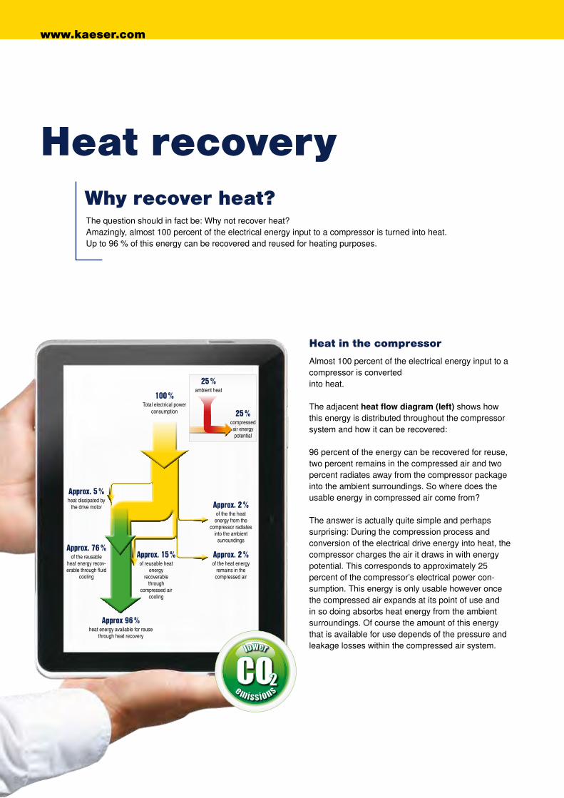
Heat in the compressor
Almost 100 percent of the electrical energy input to a compressor is converted into heat. The adjacent heat flow diagram (left) shows how this energy is distributed throughout the compressor system and how it can be recovered: 96 percent of the energy can be recovered for reuse, two percent remains in the compressed air and two percent radiates away from the compressor package into the ambient surroundings. So where does the usable energy in compressed air come from? The answer is actually quite simple and perhaps surprising: During the compression process and conversion of the electrical drive energy into heat, the compressor charges the air it draws in with energy potential. This corresponds to approximately 25 percent of the compressor’s electrical power con-sumption. This energy is only usable however once the compressed air expands at its point of use and in so doing absorbs heat energy from the ambient surroundings. Of course the amount of this energy that is available for use depends of the pressure and leakage losses within the compressed air system.
Why recover heat?The question should in fact be: Why not recover heat? Amazingly, almost 100 percent of the electrical energy input to a compressor is turned into heat. Up to 96 % of this energy can be recovered and reused for heating purposes.
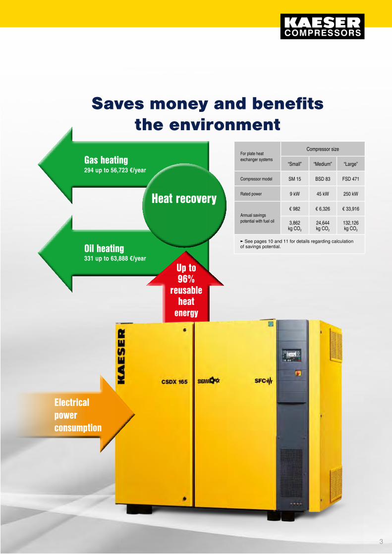
Saves money and benefits the environment
For plate heat exchanger systems
Compressor size
“Small” “Medium” “Large”
Compressor model SM 15 BSD 83 FSD 471
Rated power 9 kW 45 kW 250 kW
Annual savings potential with fuel oil
€ 982 € 6,326 € 33,916
3,862 kg CO2
24,644 kg CO2
132,126 kg CO2
Gas heating294 up to 56,723 €/year
Heat recovery
Up to 96%
reusable heat
energy
Heat recovery
Electrical power consumption
Oil heating331 up to 63,888 €/year
► See pages 10 and 11 for details regarding calculation of savings potential.
www.kaeser.com
2 3
Approx. 5 %heat dissipated by
the drive motor
Approx. 76 %of the reusable
heat energy recov-erable through fl uid
cooling
Approx. 2 %of the the heat
energy from the compressor radiates
into the ambient surroundings
Approx. 2 %of the heat energy
remains in the compressed air
Approx. 15 %of reusable heat
energyrecoverable
through compressed air
cooling
Approx 96 %heat energy available for reuse
through heat recovery
100 %Total electrical power
consumption
25 %ambient heat
25 %compressed air energy potential
Heat in the compressor
Almost 100 percent of the electrical energy input to a compressor is converted into heat. The adjacent heat flow diagram (left) shows how this energy is distributed throughout the compressor system and how it can be recovered: 96 percent of the energy can be recovered for reuse, two percent remains in the compressed air and two percent radiates away from the compressor package into the ambient surroundings. So where does the usable energy in compressed air come from? The answer is actually quite simple and perhaps surprising: During the compression process and conversion of the electrical drive energy into heat, the compressor charges the air it draws in with energy potential. This corresponds to approximately 25 percent of the compressor’s electrical power con-sumption. This energy is only usable however once the compressed air expands at its point of use and in so doing absorbs heat energy from the ambient surroundings. Of course the amount of this energy that is available for use depends of the pressure and leakage losses within the compressed air system.
Why recover heat?The question should in fact be: Why not recover heat? Amazingly, almost 100 percent of the electrical energy input to a compressor is turned into heat. Up to 96 % of this energy can be recovered and reused for heating purposes.
Saves money and benefits the environment
For plate heat exchanger systems
Compressor size
“Small” “Medium” “Large”
Compressor model SM 15 BSD 83 FSD 471
Rated power 9 kW 45 kW 250 kW
Annual savings potential with fuel oil
€ 982 € 6,326 € 33,916
3,862 kg CO2
24,644 kg CO2
132,126 kg CO2
Gas heating294 up to 56,723 €/year
Heat recovery
Up to 96%
reusable heat
energy
Heat recovery
Electrical power consumption
Oil heating331 up to 63,888 €/year
► See pages 10 and 11 for details regarding calculation of savings potential.

www.kaeser.com
54
Heat recoveryMinimise primary energy consumption for heating
Heat neighbouring rooms
When using recyclable heat for space heating, duct-ing simply feeds the warmed cooling air to where it is needed, e.g. adjacent facilities, such as warehouses or workshops.
Heating with warm air
Warmed compressor cooling air can be ducted away to provide highly effective space heating. With this method, up to 96 percent of the compressor’s input energy can therefore be recovered as heat.
The enclosed, compact design of modern rotary screw compressors makes them especially suitable for heat recovery. Direct use of the recyclable heat via a ducting system enables up to 96 % of the compressor’s total energy requirement to be recov-ered and used for heating purposes. This is the case irrespective of whether fluid-injection cooled comp- ressors or dry-running screw compressors are used.
Heat recovery a win
100 percent of the electrical energy input to a com-pressor is converted into heat. From that, up to 96 percent is available for heat recovery purposes. Use this potential to your advantage!
96%Up to
energy reusable for heating purposes

www.kaeser.com
6 7
Heat recovery
Plate-type heat exchanger
The cost-effective solution for transferring reusable heat from rotary screw compressors to heating and service water; can also be used for general process heat purposes.
Feed heat energy to a heating system
Up to 76 percent of the original input energy for the compressor system can be recovered for use in hot water heating systems and service water installations. This significantly reduces primary energy demand required for heating purposes.
Process, heating and service water
Hot water up to 70 °C can be produced from reusable compressor heat via PWT and SWT heat exchanger systems. Please contact KAESER regarding higher temperature requirements.
PTG and SWT heat exchanger systems can provide on-demand heating and service water heated to temperatures up to 70°C, or even 90°C, depending on requirement. Conventional warming of heating and service water using recyclable heat is performed by PTG plate heat exchanger systems, whilst SWT fail-safe heat exchangers are recommended for applications that have no other interconnecting water circuits and where it is essential that the water being warmed remains uncontaminated.
Minimise primary energy consumption for warming process, heating and service water
+70 °Chot

www.kaeser.com
98
Jan Mar Apr May Jun Jul Aug Sep Oct Nov DecFeb
100 %
Equipment
Heat is not only needed in winter
It goes without saying that heating is necessary during the winter months, but it is also required for significant periods at other times of the year, such as in spring and autumn. This means that heating energy is actually required for approximately 2000 hours per year.
• Chemical and pharmaceutical industries • Cantines and large scale catering establishments
Tube-type heat exchanger
In water-cooled systems, integrated plate or tube-type heat exchangers are available, depending on the available water quality. Our compressed air specialists can advise you regarding which design is right for your particular application.
Warm air heat recovery
All KAESER-rotary screw compressors can be fitted with exhaust ducting. The ducting is installed on-site. Neigh- bouring rooms and warehouse space, for example, can be heated with the warmed cooling air.
PTG plate heat exchanger system
Rotary screw compressors from the SM series (from 5.5 kW) upwards can be equipped with PTG systems. Depending on the size of the compr- essor system, the PTG heat exchanger is either integrated within the unit or is installed externally.
Areas of application • Feed into central heating systems • Laundries • Electroplating • General process heating
SWT fail-safe heat exchanger systems
Rotary screw compressors from the ASD series upwards can also be equipped with SWT fail-safe heat exchanger systems. The SWT heat exchangers are always installed exter-nally from the rotary screw comp- ressor.
Areas of application • Food industry • Tap water heating
Required heating
energy (%)
Required heating energy over the course of a yearSpace heating with warm exhaust air
Heating made easy: Thanks to the high residual thrust radial fan, the reusable (warm) air can be easily ducted away to spaces that require heating.
Image: PTG plate heat exchanger Image: SWT fail-safe heat exchanger Image: Tube-type heat exchanger Image: Internal layout of an ESD compressor – System comprising plate heat exchanger, thermostatic valve and complete pipework

www.kaeser.com
1110
bei Schrauben-kompressor
bei max. Über-druck
Motor-nenn-
leistung
Maximal verfüg-bare Wärme-
leistung
nutzbare Warmluft-
menge
Kühl-luftauf-heizung
Heizöl-Einsparpotential Erdgas-Einsparpotential
Heizöl
l
CO2
kg
Heizkosten-Einsparung
€/Jahr
Erdgas
m³
CO2
kg
Heizkosten-Einsparung
€/JahrTyp bar kW kW MJ/h m³/h K (circa)
SX 3SX 4SX 6SX 8
8
2.234
5.5
2.83.54.56.1
10131622
1,0001,0001,0001,300
8111414
473592761
1,031
1,2901,6142,0752,812
331414533722
392490630854
784980
1,2601,708
294368473641
SM 9SM 12SM 15
85.57.59
6.89.0
11.8
253243
2,100101317
1,1491,5211,994
3,1334,1485,438
8041,0651,396
9521,2611,653
1,9042,5223,306
714946
1,240
SK 22SK 25 8 11
1513.216.5
4859
2,5003,000
1617
2,2312,789
6,0847,606
1,5621,952
1,8492,311
3,6984,622
1,3871,733
ASK 27ASK 32ASK 35
815
18.522
18.021.824.9
657890
3,0003,5004,000
181919
3,0423,6854,208
8,29610,04911,475
2,1292,5802,946
2,5213,0533,487
5,0426,1066,974
1,8912,2902,615
ASD 32ASD 37ASD 47ASD 57
8
18.5222530
20.424.629.735.6
7389
107128
3,8003,8004,5005,400
16192020
4,5975,5446,6938,023
12,53615,11818,25221,879
3,2183,8814,6855,616
3,8104,5945,5466,648
7,6209,18811,09213,296
2,8583,4464,1604,986
BSD 62BSD 72BSD 81
8.5303745
35.243.452.0
127156187
6,5008,0008,000
161620
7,9329,78011,718
21,63126,67031,955
5,5526,8468,203
6,5738,1059,711
13,14616,21019,422
4,9306,0797,283
CSD 85CSD 105CSD 125
8.5455575
506376
180227274
9,4009,400
10,700
162021
11,26814,19717,127
30,72838,71546,705
7,8889,93811,989
9,33711,76514,192
18,67423,53028,384
7,0038,824
10,644
CSDX 140CSDX 165 8.5 75
9085
102306367
11,00013,000
2324
19,15522,986
52,23662,683
13,40916,090
15,87319,048
31,74638,096
11,90514,286
DSD 142DSD 172DSD 202DSD 238
98.58.58.5
7590
110132
8498
124150
302353446540
9,00014,00014,00021,000
28212721
18,93022,08527,94433,803
51,62260,22676,20392,181
13,25115,46019,56123,662
15,68618,30123,15628,011
31,37236,60246,31256,022
11,76513,72617,36721,008
DSDX 243DSDX 302 8.5 132
160148180
533648 21,000 21
2633,35240,564
90,951110,618
23,34628,395
27,63833,613
55,27667,226
20,72925,210
ESD 352ESD 442 8.5 200
250221254
796914 34,000 20
2249,80357,240
135,813156,093
34,86240,068
41,27047,432
82,54094,864
30,95335,574
FSD 471FSD 571 8 250
315278341
10011228 4,0000 21
2662,64976,846
170,844209,559
43,85453,792
51,91463,679
103,828127,358
38,93647,759
HSD 651HSD 711HSD 761HSD 831
8.5
360400450500
35384246
127138151164
10,000
11111314
7,9328,6099,46510,276
21,63123,47725,81128,023
5,5526,0266,6267,193
6,5737,1347,8438,515
13,14614,26815,68617,030
4,9305,3515,8826,386
bei Schrauben-kompressor
bei max. Über-druck
Motor-nenn-
leistung
Maximal verfügbare
Wärmeleistung
WarmwassermengeAufheizung auf 70 °C
Platzierung des PTG-Systems
Heizöl-Einsparpotential Erdgas-Einsparpotential
Heizöl
l
CO2-Einsparung
kg
Heizkosten-Einsparung
€/Jahr
Erdgas
m³
CO2-Einsparung
kg
Heizkosten-Einsparung
€/JahrTyp bar kW kW MJ/h(ΔT 25 K)
m³/h(ΔT 55 K)
m³/h int./ext.
SM 9SM 12SM 15
85.57.59
4.66.28.3
172230
0.160.210.29
0.070.100.13
External777
1,0481,403
2,1192,8583,826
544734982
644868
1,162
1,2881,7362,324
483651872
SK 22SK 25 8 11
159.4
12.03443
0.320.41
0.150.19 External 1,589
2,0284,3335,530
1,1121,420
1,3171,681
2,6343,362
9881,261
ASK 27ASK 32ASK 35
815
18.522
13.015.817.9
475764
0.450.540.62
0.200.250.28
External2,1972,6703,025
5,9917,2818,249
1,5381,8692,118
1,8212,2132,507
3,6424,4265,014
1,3661,6601,880
bei Schrauben-kompressor
bei max. Über-druck
Motor-nenn-
leistung
Maximalverfügbare
Wärmeleistung
WarmwassermengeAufheizung auf 70 °C
Platzierung des PTG-Systems
Platzierung des SWT-Systems
Heizöl-Einsparpotential Erdgas-Einsparpotential
Heizöl
l
CO2-
kg
Heizkosten-Einsparung
€/Jahr
Erdgas
m³
CO2-
kg
Heizkosten-Einsparung
€/JahrTyp bar kW kW MJ/h(ΔT 25 K)
m³/h(ΔT 55 K)
m³/h int./ext. int./ext.
ASD 32ASD 37ASD 47ASD 57
8
18.5222530
15.418.622.627.1
55678198
0.530.640.780.93
0.240.290.350.42
Internal External
3,4704,1925,0936,107
9,46311,43213,88916,654
2,4292,9343,5654,275
2,8763,4734,2205,061
5,7526,9468,44010,122
2,1572,6053,1653,796
BSD 62BSD 72BSD 81
8.5303745
27.133.540.1
98121144
0.931.151.38
0.420.520.63
Internal External6,1077,5499,037
16,65420,58624,644
4,2755,2846,326
5,0616,2567,488
10,12212,51214,976
3,7964,6925,616
CSD 85CSD 105CSD 125
8.5455575
38.648.459.0
139174212
1.331.672.03
0.600.760.92
Internal External8,699
10,90713,296
23,72229,74336,258
6,0897,6359,307
7,2089,03811,018
14,41618,07622,036
5,4066,7798,264
CSDX 140CSDX 165 8.5 75
906679
238284
2.302.70
1.031.24 Internal External
14,87317,803
40,55948,549
10,41112,462
12,32514,753
24,65029,506
9,24411,065
DSD 142DSD 172DSD 202DSD 238
98.58.58.5
7590
110132
667697
118
238274349425
2.302.603.304.10
1.031.191.521.85
Internal External
14,87317,12721,85926,592
40,55946,70559,60972,516
10,41111,98915,30118,614
12,32514,19218,11422,035
24,65028,38436,22844,070
9,24410,64413,58616,526
DSDX 243DSDX 302 8.5 132
160116142
418511
4.004.90
1.822.22 Internal External
26,14132,000
71,28787,264
18,29922,400
21,66226,517
43,32453,034
16,24719,888
ESD 352ESD 442 8.5 200
250172198
619713
5.906.80
2.693.10 Internal External
38,76144,620
105,701121,679
27,13331,234
32,12036,975
64,24073,950
24,09027,731
FSD 471FSD 571 8 250
315215266
774958
7.409.20
3.374.17 Internal External
48,45159,944
132,126163,467
33,91641,961
40,14949,673
80,29899,346
30,11237,255
HSD 651HSD 711HSD 761HSD 831
8.5
360400450500
313339372405
1127122013391458
10.8011.7012.8014.00
4.905.315.836.34
Internal External
70,53676,39583,83291,269
192,352208,329228,610248,891
49,37553,47758,68263,888
58,45063,30569,46875,630
116,900126,610138,936151,260
43,83847,47952,10156,723
For rotary screw compressor
at max. operating pressure
Rated motor power
Maximum available
heat capacity
Heated water volumeHeated to 70 °C
Installation of the PTG
system
Potential fuel oil saving Potential natural gas saving
Heating oil l
CO2Saving
kg
Heating cost saving€/Year
Natural gasm³
CO2Saving
kg
Heating cost saving€/YearModel bar kW kW MJ/h
(ΔT 25 K)m³/h
(ΔT 55 K)m³/h Int./ext.
SM 9SM 12SM 15
SK 22SK 25
ASK 27ASK 32ASK 35
Savings with PTG plate heat exchanger system
For rotary screw compressor
at max. operating pressure
Rated motor power
Maximum available
heat capacity
Heated water volumeHeated to 70 °C
Installation of the PTG
system
Installation of the SWT
system
Potential fuel oil saving Potential natural gas saving
Heating oil l
CO2 kg
Heating cost saving€/Year
Natural gasm³
CO2 kg
Heating cost saving€/YearModel bar kW kW MJ/h
(ΔT 25 K)m³/h
(ΔT 55 K)m³/h Int./ext. Int./ext.
ASD 32ASD 37ASD 47ASD 57
BSD 65BSD 75BSD 83
CSD 85CSD 105CSD 125
CSDX 140CSDX 165
DSD 142DSD 172DSD 202DSD 238
DSDX 243DSDX 302
ESD 352ESD 442
FSD 471FSD 571
HSD 651HSD 711HSD 761HSD 831
Savings with PTG and SWT heat exchanger systems
Technical specifications
For rotary screw compressor
At max. operating pressure
Rated motor power
Maximum available heating capacity
Usable volume of heating air
Amount cooling air is
heated
Potential fuel oil saving Potential natural gas saving
Heating oil
l
CO2 kg
Heating cost saving€/Year
Natural gas
m³
CO2
kg
Heating cost saving€/YearModel bar kW kW MJ/h m³/h K (approx.)
SX 3SX 4SX 6SX 8
SM 9SM 12SM 15
SK 22SK 25
ASK 27ASK 32ASK 35
ASD 32ASD 37ASD 47ASD 57
BSD 65BSD 75BSD 83
CSD 85CSD 105CSD 125
CSDX 140CSDX 165
DSD 142DSD 172DSD 202DSD 238
DSDX 243DSDX 302
ESD 352ESD 442
FSD 471FSD 571
HSD 651HSD 711HSD 761HSD 831
Savings through warm air heat recovery
Calculation example for ASD 32
For fuel oil
Maximum available heat capacity: 15.4 kWFuel value per litre of heating oil: 9.861 kWh/lFuel oil heating efficiency: 0.9Price per litre of heating oil: 0.70 €/l 1 kW = 1 MJ/h x 3.6 Cost saving: x 0.70 €/l = € 2,429 annually15.4 kW x 2000 h
0.9 x 9.861 kWh/l
For natural gas
Maximum available heat capacity: 15.4 kWFuel value per m³ natural gas: 10.2 kWh/m³Natural gas heating efficiency: 1.05Price per m³ of natural gas: 0.75 €/m³ 1 kW = 1 MJ/h x 3.6 Cost saving: x 0.75 €/m³ = € 2,157 annually15.4 kW x 2000 h
1.05 x 10.2 kWh/m³
Calculation example for ASD 32
For fuel oil
Maximum available heat capacity: 20.4 kWFuel value per litre of heating oil: 9.861 kWh/lFuel oil heating efficiency: 0.9Price per litre of heating oil: 0.70 €/l 1 kW = 1 MJ/h x 3.6 Cost saving: x 0.70 €/l = € 3,218 annually20.4 kW x 2000 h
0.9 x 9.861 kWh/l
For natural gas
Maximum available heat capacity: 20.4 kWFuel value per m³ natural gas: 10.2 kWh/m³Natural gas heating efficiency: 1.05Price per m³ of natural gas: 0.75 €/m³ 1 kW = 1 MJ/h x 3.6 Cost saving: x 0.75 €/m³ = € 2,858 annually20.4 kW x 2000 h
1.05 x 10.2 kWh/m³
Note: The highlighted potential energy savings are based on 8 / 8.5 / 9 bar compressors at operational temperature and at max. working pressure. Values may differ for other pressures.Note: The highlighted potential energy savings are based on 8 / 8.5 / 9 bar compressors at operational temperature and at max. working pressure. Values may differ for other pressures.
Savi
ngs
pote
ntia
l for
150
0 hr
s
Savi
ngs
pote
ntia
l for
150
0 hr
s
Savi
ngs
pote
ntia
l for
200
0 hr
s
Savi
ngs
pote
ntia
l for
200
0 hr
s
Savi
ngs
pote
ntia
l for
150
0 hr
s
Savi
ngs
pote
ntia
l for
150
0 hr
s
Savi
ngs
pote
ntia
l for
200
0 hr
s
Savi
ngs
pote
ntia
l for
200
0 hr
s

As one of the world’s largest manufacturers of rotary screw compressors, KAESER KOMPRESSOREN is represented throughout the world by a comprehensive network of branches, subsidiary companies and authorised partners in over 100 countries.
With innovative products and services, KAESER KOMPRESSOREN’s experienced consultants and engineers help customers to enhance their competitive edge by working in close partnership to develop progressive system concepts that continuously push the boundaries of performance and compressed air effi ciency. Moreover, the decades of knowledge and expertise from this industry-leading system provider are made available to each and every customer via the KAESER group’s global computer network.
These advantages, coupled with KAESER’s worldwide service organisation, ensure that all products operate at the peak of their performance at all times and provide maximum availability.
KAESER – The world is our home
www.kaeser.com
KAESER KOMPRESSOREN AG P.O. Box 2143 – 96410 Coburg – GERMANY – Tel +49 9561 640-0 – Fax +49 9561 640130www.kaeser.com – e-mail: [email protected] P-
645E
D.15
/13
Spec
ificat
ions
are
sub
ject
to c
hang
e wi
thou
t not
ice.