Embed Size (px)
Citation preview

AD/A-002 218
HEAT TRANSFER DESIGN AND PROOF TESTSOF A RADIOISOTOPE THERMOELECTRICGENERATOR
Earl J. Beck
Civil Engineering Laboratory (Navy)
Prepared for:
Naval Facilities Engineering Command
November 1974
DISTRIBUTED BY:
National Technical Information ServiceU. S. DEPARTMENT OF COMMERCE

UnclassifiedSECURITY CLASSIFICATIO, OF THIS PAGE SWSet, fI-r0- 1t,
REPORT DOCUMENTATION PAGE .READ INSTRUCTIONSREPORT_______________PAGE_ EFI-ORE COMPLETING FORMI REPORT NUMBFR - 2 GOVT ACCESSIIN NO. 3 RECIPIENT'S CATALOG NUMBER
TN-i1359____ __ 74 TIF'.'" TYPE GF REPORT & PERIOD COVERED
HlEAT TRANSFER DESIGN AND PROOF TESTS Final; Nov 1972-Jul 1974OF A RADIOISOTOPE THERMOELECTRIC 6 PERFORMING ORG REPORT NUMBER
GENERATOR7 AUTHOR, B CONTRACT OR GRANT NUMBERI,)
Earl J. Beck
9 PERFORMING ORGANIZATION NAME AND ADDRESS t0 PROGRAM ELEMENT PROJECT TASK
CIVIL ENGINEERING LABORATORY AREA A WORK UNIT NUMBERS
Naval Construction Battalion Center 63724N, Y41Wi, 43-016.Port Hueneme, CA 93043
11 CONTROLLING OFFICE NAME AND ADDRESS 1Z REPORT DATF
Naval Facilities Engineering Command November 1974
Alexandria, VA 22332 13 NUMBER OF PAjES
tA MONITORING AGENCY N AME B ADO.ESS-I 1l1er 1, 1 ITIH'I ( ,, ,n Oil-fe 15 SECURITY CLASS
UnclassifiedIS, D L ASSEIC A'ION OWNGRAG -
SCHEDijL F
16 DIS'RIBUTTON STATEMENT I ',- Hep.,
Approved for public release; distribution unlimited.
17 D1ST HIBUTION ST ATEMENM T 'o .1 10 1 ( ,lhl flC IT RI A 20. / .IIII,'rII I&,0-1- R1 potrI2
I8 SuPP..EMENTARY NOTES
19 WFY ROADS &, Ilne 1n 1.1-er. rIlP iI n *' - A eI rp1S I , 1,1,,, O ID5i $.
Thermoelectric gcncrator, I - 'G. radioisotope powered, electrical power, underwater power,heat transfer, natural convection, under-ocean heat rejection surf-ie
2S ABSTRACT CTI HIICn P , - rt de II Het e, .e I- d t1l, V -H 6i1,III1- ,,.
In support of a larger effort of the Nuclear Division, Naval Facilities EngineeringCommand, CEL undertook to design, build, and test the heat rejection portions of alarge 2-kw(e) radioisotope thermoelectric generator (RTG). The design was optimizedto produce the lowest practicable temperatures at the cold junction of a large number ofthermoelectric heat-to-electricity conversion elements. The geometry was largely defined
continued
DD I FOAN, 1473 EDITION OF I NOV 65 15 OBSOLETE UnclassifiedSECURITY CL ASSIFIC ATION 'CF THIS PAGE SRShn lir *H-eed
Peproduced by
NATIONAL TECHNICALINFORMATION SERVICE
US D.E l.t fl, .i CommerceSp,, fi.lId, VA. 22151

UnclassifiedSECURITY CLASSIFICATION OF THIS PAGE(Wh.., Data Entered)
20. Continued
by the sUe, shape, and required number of thermoelectric elements and by theirdeployment at the upper end of a large pressure-resistant hull. The work showedthe capability of the 12-finned convectors to maintain a temperature below 90°Fat the inner face of the convectors both when the unit was vertical and when tilted60 degrees from the vertical. The solid copper showed no signs of corrosion; thepotential corrosion problem is discussed in some detail in the report, as are relatedproblems of flow, protection, and possible fouling from marine growth.
UnclassifiedSF(" U ITY CLASSI III$ATION nv THIS PAOCE'M1I.-, fr)At 1,tered)
I'

INTRODUCTION
As one of several activities supporting the Nuclear Division ofthe Naval Facilities Engineering Command in developing a large 2-kw(e)undersea radioisotope thermoelectric generator, the Civil EngineeringLaboratory undertook in late 1972 the design optimization, construction,and testing of the necessary heat rejection modules.
All known methods of converting heat to electric power inherentlymust reject a certain amount of the available heat to the environment.
Because of their relatively low efficiency, thermoelectric generatingelements reject a relatively large amount of heat, some 28 to 30 kw fora 2-kw(e) unit. The cold waters of the deep ocean are excellent forreceiving heat, and the potential exists for attaining a near-m-ximumefficiency by keeping the cold junction of the thermoelectric conversionunits as near the ambient ocean temperature as is practicable. The colderthe cold junction, the better the efficiency and, probably, the lifeof the elements.
The practical foundation for convection heat transfer, entirelyadequate for the planned use here, is well laid in extensive theoreticaland empirizal work in the open literature. This work was specializedand extended for the ocean applications in a comprehensive study conductedby and for the Civil Engineering Laboratory by Braun in 1965.* This studyincluded resolution of former discrepancies in published works and extended
the resulting correlations to a design method and tests in shallow anddeep water in the ocean off Southern California. This work so completelysummarizes previous efforts that it is the only reference to be usedhere. It is far too comprehensive to be abstracted, so its results willbe used directly with a minimum of discussion; they relate to design,corrosion, and marine fouling of heat transfer surfaces as well as consid-eration of the probable height of a heated plume over a natural convector.
Certain assumptions are made by Braun, page 11-25 'Optimium FinGeometry in Free Convection,'' some of which, while appropriate forindustrial heat transfer devices, were not all appropriate in this appli-cation.
Assumption: 1. Steady-state heat flow. Valid, and realistic in theocean.
Assumption: 2. Homogeneous fin material and constant fin thermalconductivity. Valid, at least for the first trialdesigns. The possibility of incorporating ducting(heat pipe type passages) within the fins may beconsidered later, which would invalidate this
assumption.
C. F. Braun Co., Alhambra, CA. ''Study of heat transfer and fouling
cf heat transfer surfaces in the deep ocean-final report,'' Contract
NB 32274, 26 November 1965.

Assumption: 3. Constant heat transfer coefficient over the faceof the fin. Not valid, but a useful first approximationin developing a fin cross section using the techniqueof an analog computer basad on resistive paper.
Assumption: 4. Uniform temperature in tae surrounding fluid. Obviouslynot strictly valid, but a useful approximation as inAssumption 3.
Assumption: 5. No temperature gradients occur along the length andacross the thickness of the fin. Invalid, but approx-imately correct for very high conductivity in thefins (copper, silver, etc.) and low surface coefficient.
Assumption: 6. Temperature at the fin base is uniform, and there isno contact resistance at the fin base. Valid, firstpart approximately correct for high-conductivitynaterials such as copper; second part valid formost construction methods, including brazing, casting,and soldering.
AssumpL4 on: 7. There is no heat source within the fin itself. Validfor solid fins. With internal ducting, as with heatpipe channels, not valid.
Assumtion: 8. Heat transfer from the fin end and sides is negligible.Valid for all but thickest and shortest (in directionof water flow) fins.
The usual industrial criterion for heat transfer surface optimizationis cost, and the methods outlined in the reference are based on costconsiderations. For the present design, the relatively low cost of theheat rejection surfaces no matter how constructed appeared trivialcompared to the probable costs of the remainiier of the RTG design. There-fore, a design method based on the following crit ia was adopted:
(a) Within the physical constraints of size based on the number andsize of the pre-existing thermoelect:ic units, provide a minimum basetemperature at the cold junction of the thermoelectric units.
(b) Provide as uniform a base temperature as practicable, whichmeans a fairly heavy section of high-conductivity material.
(c) Provide the necessary strength in longitudinal cotipressionfor the intended overpressL-es. The thermoelectric units are fabricatedby an intense swagging process and can provide the necessary strengthin the radial direction.
(d) Provide a maximum of protection against corrosion.
(e) Provide a maximum of protection against marine growth.
(f) Fabricate by a method that will insure optimum quality control.For the immediate demonstration experiment, fabricate to as nearly thefinal design as practicable by a low-cost method.
2

The remainder of this report describes the design methods, the finaldesign selected, the results of controlled tests in a large tank of seawaterat CEL, and the results of a 30-day immersion in Port Hueneme Harbor.
DESIGN AND OPTIMIZATION OF THE HEAT TRANSFER MODULES
Previous criteria provided by the sponser, required that some 28 kwof heat be rejected in 12 vertical modules of the overall dimensionsshown in Figure 1. All of the useful heat to be converted in part toelectricity must be transferred radially from a high temperature heatpipe in an area as sho i. To provide for compression strength in thelongitudinal direction, at least 3/16 inch of most copper alloys wouldbe required, not crediting the additional strength and rigidity providedby any fins used in the final design. A thimble thickness of 1/4 inchwas arbitrarily selected to utilize readily available materials. Basedon a design overpressure of 10,000 psi (approximately equivalent toa 20,000-foot immersion depth in seawater), the resulting longitudinalcompressive stress in the 1/4-inch-thick thimble is:
S 7(D 2/4)P 2- p 16,500 psi* (1)c 7T(D2 - d2 )/4 D2 - d2
for the dimensions shown in Figures 2 and 3, or about 1/6th the probablecompressive strength for structural copper; stronger alloys would providean even greater margin, as would any heavy fins--an almost certaineventuality in this type of convector. The heavy section is desirable toproduce even temperatures at the minor diameter, d, and a long life inthe presence of corrosion.
Seawater is an excellent cooling medium; however, for the relativelyhigh unit area heat loading of 2,600 watts on a 0.308-square-foot basearea,
Q/A (2600)(3.4) 28,700 Btu/(hr)/(ft 2 )0.308
an extended surface consisting of a number of vertical, heavy fins willalmost certainly be needed to produce a low base temperature.
As a first trial, the following calculation was made of the temper-ature drop through 70-30 copper-nickel:
* See List of Symbols after Appendix B.
3

-K A At x Q = (0.25)(8,850)Q ; At = -K A (200)(0.378) or 29.60F (2)
for a 1/4-inch-thick thimble. While not unreasonably high, it wouldproduce base temperatures well over 100°F with natural convection heattransfer to 40°F seawater. Much better results would bc obtained withcopper. For the Cu-Ni case, the temperature drop from the base would beapproximately as shown schematically in Figure 2. This figure also showsa first estimate of the full-scale cross section of idealized heavy fins.Tli final shape and height, H, selected were eventually modified to reducemanufacturing cusLs and to avoid interlocking of the fins of adjacentmodules on the prescribed base circle (21.25 inches diameter) for the12 modules. The results are slightly nonconservative compared with theideal shape (Figure 2) with ample tillets at the base and parabolic =_C
section. That is, the more expensive, longer fins would provide slightlybetter cooling; the difference is marginal.
The bare thimbles would have a base temperature well over 2000 F,which would be undesirably high. An extended surface (fins) to produceadditional heat transfer area is clearly indicated. Because of the highheat loading, the optimum fins will require: (a) heavy cross section,to avoid excessive temperature drop along their length, (b) a materialof high thermal conductivity for the same reason, and (c) as close spacingas practical without reducing flow to the base.
ThQ actual value of the film coefficient, h, is determined by thewell-known dimensionless equation as refined by Braun (1965) for seawater:
Nu f(Pr) (Ra)n (3)
in which f is an experimental constant and the exponent n is typically1/4 up to Grashoff's number of about 109, and 1/3 above 109 . The lowervalue is associated with laminar flow, the higher value with turbulence.
For the fin length, L, dictated by the design and the physicalproperties of seawater at pressures equivalent to 20,000-foot depth:
c = 0.95 Btu/(lb)(F)
= 64 lb/ft3
= 1.66 lb/(ft)(hr)
K = 0.385 Btu/(hr)(ft2 )(OF/ft)
8 = 1.13 x 10⁴ /OF
= 0.5 ft
g = 4.17 x 100 ft/(hr)(hr)
Pr = c p /K = 5.68 (dimensionless); at 1 atmosphere, this is
about 4.5
4

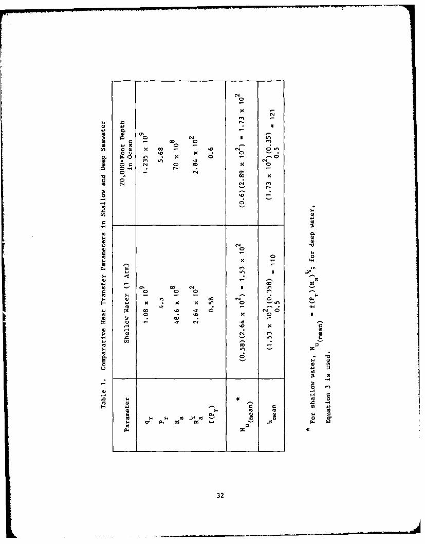
While the design is for the deep ocean, say 20,000 feet, theimmediate results must be related to 1 atmosphere; comparable values ofthe important physical properties and resulting dimensionless numbersare tabulated in Table 1. Because of the small change in physical prop-erties in the direction of imptoved heat transfer with depth, resultsfrom the 1-atmosphere tests are slightly conservative--metal surface
temperatures will be slightly lower in the actual deep-ocean applications.The f(Pr) is shown as a function of Pr, Figure 3, and the values for theshallow and deep water indicated in the curve. For the remainder ofthe rcport, shallow water values only will be used.
OPTIMIZATION OF EXTENDED SURFACES--ITERATIVE APPROACH
Referring to Equation I and Figure 1, it is obvious that the onlyphysical aspect of the heat rejection surface related to h is the height,L, which is fixed by the dimensions of the thermoelectric elements to be
used. The other important parameters are the physical properties of thefluid, the temperature difference (At), and the exponent--which is assumed
to be 1/4, as the Grashoff's n'juber is about 109, the approximate upperlimit for laminar flow (Braun, 1965). Table 2 gives some estimates ofthe effect of varying the surface temperature on the convection filmcoefficient, h, the resulting heat rejection of a bare cylinder, andthe increase in area per each of the 12 modules necessary to reject thedesign value of 8,850 Btu per hour per module.
Because all of the neat transferred from the base area through theextended fin surface must be moved through the fin metal with a loss intemperature proportional to the fin conductivity, there is an obvioustradeoff between iong, slender fins (dimension H, Figure 2) to obtain amaximum usable area and short, stubby fins to produce a high surfacetemperature (minimize temperature drop) and a resulting high convectioncoefficient, h. Because the heat transferred is proportional to the areaand to h, and because h varies as the 1/4th power of the temperaturedifference, there is no simple linear relationship allowing a directapproach to establishing proportions. Using criteria listed earlier, afirst design of a possible shape is snown, Figure 4. This stubby fin has
approximately 2.5 times the area of the base cylinder and from Figures5, 6, and 7, this fin should have a surface temperature of about 130°Fwhen transferring the necessary heat to 40°F seawater at low pressures,
if made of copper.A similar, much longer fin made of aluminum (K = 1,500, Table 3)
would have temperatures approximately as shown in Figure 8. This is thefirst result of the use of an analog computer which utilizes a highresistance paper to simulate heat conduction and a millivolt meter toread voltages, which simulate temperature. In Figure 8, the surfacewas divided into ten segments and the surface temperature estimatedfor each. The method is very rapid and powerful, in that simple shapescan be rapidly produced, and substitution of various fin materials can
5

be made by varying the current to achieve the desired voltage drop across
the base 1/4 inch. At the de~ign heat load, a copper cylinder 1/4 inchthick has a At of about 20 F. All other potentially useful materials areof lower conductivity, so they will have a greater temperature drop; foraluminum, this is 3.6 F.
The actual resistance paper used for these and most later iterationsis shown in Figure 9, and includes not only the field with pricked pointsat the grid intersections, but a varying resistance area allowing simula-tion of the resistance provided by the film coefficient, h. By biasingthe outer border to 40°F with an external electrical resistance it ispossible to obtain direct voltage readings at any point on the surfacewhich are equivalent to the temperature. Figure 10 shows the same crosssection, with temperatures plotted for a first single module designedto provide a prototype for the full-scale 12-module system, shown inFigure 11. This single module is shown schematically in Figure 12 in
partial section full size, and in elevation 1/4th size, with some detailsof its construction. Its method of construction allowed two desirable
features: a complex, 'ideal' shape at low cost, and a copper sheath towhich could be directly attached a single constantan wire forming athermocouple junction by which precise surface temperatures could beobtained. The succession of steps followed in checking the design was:
(a) Prepare, bias, and take readings of a preliminary resistancepaper half section, four times full size.
(b) Build the prototype, lead-filled single module and equip withelectric heaters and a heat transfer liquid consisting of approxiilatelytwo parts water and one part ethyl alcohol, enough to cover the electricheaters while in the vertical position.
(c) Test the lead-filled prototype in a small tank at two tempera-turces of water--one at about 700F, ambient for the Port Hueneme area,and one at about 400 F, using ice water.
(d) Repeat the ambient water tests with the module tilted 30 and60 degrees from the vertical (a small trunnion was used to maintainstability).
(e) Fill in the field of temperatures, using an electrical biasto reproduce the measured values. Figures 10(a) and 10(b) show the se, iontemperatures at mid-elevation; the temperatures underlined are measured.
The values obtained are recorded in Tables 4 and 5. There was noindication of local overheating or insufficient cooling in any of thesefirst test,.
6

FULL-SCALE PROTOTYPE E-k'ERIMENT
Following successful verification of the design to this point usingthe single lead-filled module (which for purposes of this report is notconsidered to be a valid experiment, but a design device), 12 full-scalemodules made of solid copper were fabricated (Figure 13). Details offabrication are shown in Figure 14. In effect, each of the 12 coppermodules is a small boiler or upper terminus of a heat pipe heated bythree electrical immersion heaters of 1,000 watts nominal rating each.
To allow the use of fins of copper, the best material, and at thesame time allow fabrication at reasonable cost, stubby rectangular finswere used. Further, this was necessary to avoid interlocking of thefins on the tight circle prescribed by the design; the loss of the extraarea had negligible effect on the base temperatures as will be shownlater. When the complete RTG is built, there may be a small advantage
in using the complex, higher fins--that is, longer in the radial direc-tion, Figure 2. This wc.'ld require either interlocking the fins orincreasing the diameter of the major circle on which the 12 modules aremounted. A close-up view of the copper heat rejection modules is shownin Figure 15, and an underwater view of the completed experiment withinstrumentation as tested in CEL's 60,000-gallon tank of seawater inFigure 16.
All temperatures were read from a manually balanced, direct readingportable Leeds and Northrop potentiometer, with a rapid-response electronic
null meter. The calibration allowed reading to within 1/2°F, and esti-mating somewhat more closely. Thermocouple locations are shown in Figure17.
Tests of the full-scale device, Figures 11 and 16, were conductedin ambient temperature water in the vertical position as shown and at30 and 60 degrees from the vertical, without and with a protective shroudwhich mounted in the four 1/2-inch holes which can be seen adjacentto the modules, Figure 13.
The very large volume of water in the tank made it impracticableto reduce the ambient water temperature appreciably with ice withoutincurring excessive cost and reducing the salinity. One loading of icewas used, and the data are identified in the tabulation of results. Thefreshwater tended to stratify on the surface as the ice melted because
of its lack of salinity. An effort was made to stir the water in thetank, with uncertain results. The normal temperature gradient in thetank from top to bottom was measured at about 2 F.
The only irregularity in experimental procedure occurred when thecomplete experiment was left in the seawater test tank over a weekend.The single-module lead-filled prototype had as a precaution been ventedto avoid pressure build-up in the event of insufficient heat transfer.Provision was made for venting on the full-scale experiment, but theholes were plugged as a simplification, inasmuch as no pressure build-up had been observed in the first prototype. Apparently a faulty O-ringsealing the water-alcohol mixture allowed leakage past the heater elements
7

in five of the 12 modules. This was observed as an excess electrical loadand, while none of the heating elements burned out, they were replacedwith new units, and precautionary venting was provided. None of the dataincluded in this report are of tests with defective wet insulation inthe heating elements.
DISCUSSION OF RESULTS
The entire point of the experiment was to validate the capability ofthe module design to dissipate the required heat, measured electrically,and to provide low temperatures at the locations of thermocouples Ml,M2, and M3 which are on tle surface where they would be in intimate
contact with the cold junctions of the thermoelectric units in the actualRTG. The results are tabu-ated in Tables 1 through 8. A run consistedof adjusting the electrical input to the desired value and observingtemperature rise until the inner temperatures were stabilized. Becauseof the rapid cooling of the seawater, the high thermal diffisivity ofthe copper fins, and the small mass of the water-alcohol mixture contained
in the heat pipes, temperature stability was typically achieved in aboutan hour from cold start-up and even more rapidly with minor adjustmentsin power input. To insure stability, a typical run consisted of a 1-1/2to 2-hour stabilization periou, followed by taking a single set of read-ings.
With the exception of failure of the O-rings containing the alcohol-water mixture as discussed above, there were no observed irregularitiesnor unexpected temperature anomalies.
While the nominal required heat input to the 12-module experimentwas 28 kw total, some tests are for a higher power dissipation, 32 kw.Thi is slightly over the design heat load, so that the maximum temper-ature- recorded are somewhat higher than the values which might be expectedin a newly fueled RTG deployed in deep-ocean water at, say, 40°F ambientseawater temperature. The temperatures as recorded in the tank tests areshown in Tables 4 and 5.
An appreciatioa for the lineatity of the metal te'perature changeswith change in ambient seawater can be obtained from Table 6, which givesboth the temperatures of the lead-filled single module at two watertemperatures, and the differences. With a difference in water temperaturesof 350 F, no measured temperature differences greater than 480 F wereobserved. The most important single temperature, because it is physicallyclosest to the base, is T6. For this location, dropging the water temper-ature by 350F caused a metrl temperature drop of 43 F, a conservativedevelopment in assessing the eventual consequence of irmaersing a full-scale RTG in very cold, deep-ocean water.
Summarizing the results shown in Tables 7 and 8, there was no evidenceunder any of the conditions of test of poor flow to and around the moduleswhich cause excessive temperatures or poor cooling. The effect oT, the
inside metal temperatures, those seen by the thermo-electric modules, of
8
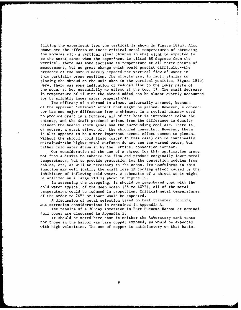
tilting the experiment from the vertical is shown in Figure 18(a). Alsoshown are the effects on tnese critical metal temperatures of shroudingthe modules witn a vertical steel chimney in what might be expected tobe the worst case; when the experi-ent is tilted 60 degrees from thevertical. There was some increase in temperature at all three points ofmeasurement, but no great change which would predict difficulty--thepresence of the shrcud merely impeded the vertical flow of water inthis partially prone position. The effects are, in fact, similar toplacing the shroud on the unit when in the vertical position, Figure 18(b).Here, therc was some indication of reduced flow to the lower parts ofthe modul-s, but essentially no effect at the top, Ti. The small decreasein temperature of Ti with the shroud added can be almost exactly accountedfor by slightly lower water temperatures.
The efficacy of a shroud is almost universally assumed, becauseof the apparent 'chimney' effect that might be gained. However, a convec-tor has one major difference from a chimney. In a typical chimney usedto produce draft in a furnace, all of the heat is introduced below thechimney, and the draft produced arises from the difference in densitybetween the heated stack gases and the surrounding cool air. There is,of course, a stack effect with the shrouded convector. However, thereis w, ut appears to be a more important second effect common to plumes.Without the shroud, cold fluid (water in this case) can be continuallyentrained--the higher metal surfaces do not see the warmed water, butrather cold water drawn in by the ertical convection current.
Our consideration of the use of a shroud for this application arosenot from a desire to enhance the flow and produce marginally lower metaltemperatures, but to provide protection for the convection modules fromcables, etc, as will be necessary in the ocean. Its usefulness in thisfunction may well justify the small loss in cooling effect caused by theinhibition of inflowing cold water. A schematic of a shroud as it mightbe utilized on a large RTG is shown in Figure 19.
In assessing the foregoing, it should be remembered that with thecold water typical of the deep ocean (36 to 400 F), all of the metaltemperatures would be reduced in proportion. Critical metal temperaturesof the order to 70°F or lower would be expected.
A discussion of metal selection based on heat transfer, fouling,and corrosion considerations is contained in Appendix A.
The results of a 30-day immersion in Port Hueneme Harboi at nominalfull power are discussed in Appendix B.
It should be noted here that in neither the Laboratory tank testsnor those in the harbor was bare copper exposed, as would be expectedwith high velocities. The use of copper is satisfactory on that basis.
9

CONCLUSIONS
1. The design utilizing solid, heavy, short fins on the 12 modules shouldproduce cold junction temperatures in the actual RTG of 70 F or lower inthe deep-ocean (cold water), or about 350 F above the ambient temperature.
2. Tilting of the RTG up to 60 degrees from the vertical does not seriouslyaffect the capability of the convectors to reject the heat produced;therefore, strict verticality will not be a critical requirement in theocean.
3. The use of a shroud around the convectors to provide a 'chimney' effectis not justified in terms of efficiency; the elimination of the cold watermore than offsets any advantage from increased vertical convection.
4. The use of a shroud around the convectors to provide mechanicalprotection from the projecting convectors and other appurtenances suchas electrical connectors which might be placed within the convectorcircle does not materially inhibit heat transfer, and may be justifiedon the basis of safety in spite of a small decrease in electrical output.
5. For the flow conditions produced at the power inputs used, thevelocities are not high enough to cause washing of the copper surfacis;the use of copper, an optimum material from a heat transfer standpoint,is both justified and highly desirable in this application.
10

-L C>
~-0 - - L
Ci LL - Cz =O
I -C 0
0 UE 0.
E oCL T.
= o
0
w -i
-j C,
'Lli~~~- 68- Jaa e( C~aLL
Xi 4 0
- C
7- u0
(L)
o - CD
m >~
w 2 0E
w_ - 0
c 0~ . cj EI0 c)l
w11

0.8~
20.000 It
0.1 atmosphere
0.56
0.4
Q.-
0.2
Prandtl No., Pr- for Seawaterl 10
Figure 3. Variation in f Pr as Pr varies (in this case by depth and temperaturechange in the deep ocean).
Figure 4. Cross section of a stubby fin(6 on each mod'it') with an
arca rdtio, Rf. of 2.54.
12

10,000 t I I tProbable trend (not calculated) at high /Ats where turbulence might be expected .. k esi . I
Probabe tred (notcalcuated) t hig utf esign Value of
8,000
U-
6.000
4,000 Calculated values I-/ (assumes laminar flow)
2000I
0 L40 80 120 160 200 240 280
Assumed Surface Temperature, t w (OF)
Figure 5. Heat transferred from bare cylinder as a functio, of
surface temperature.
10 I I
at 400
F surface temperature
7.5
7.5 Note: Replotted next sheet
on log-fog paper.
5
Design Point A
2.5
40 80 120 160 200 240 280
Assumed Surface Temperature, t w (OF)
Figure 6. Area ratio necessary to attain desired base surface temperature.
13

-- 7
100
80
70
60
50
0
30\
20
10
u 9
8
7
6
5
4
3
2
10 20 30 40 50 60 70 80 90 100 200 300
Assumed Surface Temperature, tw (OF)
Figure 7. Data for Figure 6 plotted on log-log coordinates showing extrapolation
to very low surface temperatures.
14

88.2
88.4 Ao,-2(50.5 - 48.7) 3.60 F
(Approx. K (2,7001(2/3.6) - 1,500088.4
88.8
089.4 888 89.2
89.889.4
4 90.6
9 .
91.2
S92.4 92 9?
93.4
93.3
~94.4
.95.8 95.2
_.97.4 97 97
99.4
0 1
Figure 8. Representative results from analog computer. Values shownwould be for metal with conductivity of aluminum.
15

Figure 9. Actual high-resistance surface analog computer with connector wires.
16

7 Numbers are temperatures, OF
71 71
072 72
726 T72 T I073 73 0
T3
74 ~ TE I T273 0 74T5.,
T1 T2 ..
Location of Thermocouples0 75
76 075
Test data are underlined. All numbers are
79 078 077 75 temperature, OF. Temperatures not under-lined were filled in using an electricalanalog computer.
82 @82 079 76
41 (seawater)087 e86 084
T6 -193 .92 Note that in spite of the greater area than in90C,= -, the stubby copper fin, the base temperature
1is ilmost 30°F higher, due to the relativelypoor conductivity of lead. The results withlead are typical of what could be expected
- with copper-nickel alloys.
121to
Figure I0(a). Computer output for fins made of lead. Underlined values are
experimental, and computer was used to fill in the field.
17

I
88.8 - - 88.4
* 88.8
88.8 88.8
Four times full size088.9 Water temperature, 40OF
Temperature profile obtained by electrical8.9 6 9.9 analog computer, with temperature dropbased on the thermal conductivity ofcopper and estimated film transfer
9 89.2 coefficients, verified in previousexperiments.
All numbers are temperature. OF.
I .89.7
90.2590
91/ Note: The computation method requires91 certain assumpiors which may change theS91/ actual values up or down by I to 2 degrees;91.7 the fractional temperatures wr'uld not be92 .91.5 justified on that basis. However, the method
92 does provide accu-acy, of the order indicatedin establishing tems~iature gradients.
Figure 10(b), Comparable computer output for stubby Copper fins used in the12-module experiment. All values shown are calculated.
18

.... ... ..-..
Zi "I
Figure 11. Full-scale 12-module heat transfer experiment, showing upper ends of heat pipes.with one finned module in place.
19

12 fins, formed coppersheet, tinned innersurface
virgi '-t filled
~-3-in, copper tubing, 12 in. long,tinned center 6 in.
12-in.-long,3-in.-diamcopper pipe
o-lead-filledcopper fins
Figure 12. Details of construction of lead-filled exploratory module.
20

Figure 13. View from above showing 12 heat transfer modules before instrumentation.
21

NI lLi
11 r
II
ILI
,
E
Ti ill
22
( -~--~---

0 : 3 4 $
S. NAVAL CIVIL ENfINEERING LAB
I
Figure 15, Close-up of finned modules showing close packing which limited
length of fins.
23

Figure 16. Full-scale 12-module experiment in NCEL saltwater tc~t tank, showinginstrument leads and electrical power cable.
24

V shroud
I I
Notes: (1) <Mi, <Wi indicate positioning of andN numbering of thermocouples in metal
and water, respectively.
(2) All thermocouples to be of nyloninsulated, copper constantan, 24 gage,
M2,) M5 installed to minimize distortion ofM2 M4 M temperature field or weter tlow. Wire.I 7pairs will be used in water, but single
M8, 9 constantan wire peened into copper(ext I(int) for all metal temperatures, with
common copper return.(3) Readings to be manually recorded,taken on direct reading potentiometer.
(4) Complete instrumentation as shownM3 I will he applied to one module, with
similar critical measurements on
<W10 adjacent module for comparison.
(5) Mid-fin measurements, similar to <M4will be made on one interior fin of everyother (six modules total) module, forcomparison.
(6) Distances of and position of thermocouplesin water may be adjusted following firsttrial tests to insure meaningful readings.
M6
Note; Temperatures indicated in Table 8 areM8 at locations in an adjacent module, similar to
M4-M9.
P M9
Wi 1
Figure 17. Schematic of copper moduleshowing thermocoiuple locations.
25

o x
0 .
7iE a
,c. 0 Xc 2 C c0 3 W
0 B 0
C 0N
C.,o 0 0D 00
(=Io) ainejadwajL
E0 0)to)
-ON w
0)
CD :
Q)
av)
o a)(D
00 0
(:Io a)ejdw
26) 4

tto condenser orwaste to atmosph~ere
removable shrou
ri IIfreshwaterII I Its 22OP~F maximumn water
boiling at 1 atmosphere
radiation and convectionl
tv ambient temperatureplus approximately
tw
Figure 19. Simplest arrangement for cooling heat pipes during storage or shipment
where water supply is limited, as on trains. System requires makeup ofabout 3 gallons of water an hour.
27

C-0
a)
E
-cC0S
a)
a)
-o0a)
za)Sa)Ca)
IC*~,0
Ocva, C.
-c
a) (VS F
.t 0-C
kcbN
0(NCi
a))U-
28

.2
I In
0 m 0
4) M C
4) w
* ~0;
00E ci
41N
II .- b
LL4
I to(:Io 0ijjaw
29_

N4
I.I
Figure 22. Closeup of RTG heat transfer modules immediately after removalfrom Port Hueneme Harbor, 30 day immersion.
Figure 23. RTG upon removal from 30 day immersion, Port Hueneme Harbor,
showing non-adherent scum on partially rusty simulated hull.
30

0=
AL!
Figure 24. Closeup of RTG heat transfer module fins, following drying,showing early indication of marine growth.
31
______________________________________________ _______________ ______CIA __
(n
mi 4) y0- cii V)
En 0 0)x c0i (~ 00 -
o1) 9: 00. "4-i IA * X0
Vi 0 0N 0 x~~~C 0cn* ~
0
co
-4 *4
cc 0
ca
a%. 00 04N r
W. 4)(N c
m. - 44I
0 CI
.H AA fL
(I~~0 0'0 ' NL
0 0) 0
5-'~ ~ enIA( 00
Cu W ~ C r
rm A 0 iN
$4 0 4 od '0 44 0 ttv 3 0 .
0 - - (N -
32 5

Table 2. Calculating the Effects of At in ShallowSeawater Tests (Independent variable;
surface temperature, tw)
Assumed Q/W.O.b Fin AreaSurface At a/..FnAe
rfate, A At h a Fins Ratio, Rf.Temperature, (OF) w mean (Base area to Reject
tw of fin) 8,850 Btuc(OF)
160 120 3.31 110 5,000 1.76
80 40 2.52 84 1,270 6.95
120 80 2.99 100 3,020 2.92
200 160 3.55 118 7,200 1.22
240 d 200 3.76 125 9,450 0.93
a Based on Approximation 1/4
mean tw 16 0 t 0 ) = llO(At)
e.g., for tw = 80, h80= (110) G:73 = 84
b Based on Q = h AAt, where A = 0.378.
cRf is defined here as surface area ratio of a particular
fin system to a plain cylinder of same root diameter, with
average surface temperature as shown.
d Valid approximation at depth in ocean. In shallow water,
boiling would keep t below about 216 0 F.
w
33

Table 3. Thermal Conductivities of SomePotential Building Materials
Thermal Conductivity, kMetal [(Btu/(hr) (ft2) (OF/in.)]
Silver 2,900a
Copper 2,700
Aluminum alloys 1,500
Magnesium alloy 360 c
90-10 Copper-nickel 310
70-30 Copper-nickel 200
Lead, pure 240
Monel 174
Stainless steels 90 to 180
Hastelloy (d) 145
Titanium, pure 118
Typical alloy 60
a Shown for comparison; has highest value
of any known metal.
b Maximum.
c Typical.
34

4) Q
a) 4) 4
3 41
04 Q-4 cw 4-Q )
l Sa -4q) ) 4- .C Jd) JU Q) 4. r
> . H k- cc 0 C3
0 $4r. ) M 04-' 0) -H $- a)4 40
ruCZ E .3. gcu o-W~v cc C) 0 Qr
4 0 0
(n~ -C.1-l L W 4
Q)LIn
C.Y
E Ln00 - r U' 1 J13 1
C. F-n a, a'1 a, a, a, a,
-4
F- c o M Y c c o, - oF- Lfl') . Lfn tUf LC') cr4 L- cr4c
a, Q. cr
C. 0 -.- F- c 4 o ' c c C NO 4
< 4 14c-
4) 0
*Lc r) CC 11 00 mC "- I -T L-. cr) CD
-4 LLC.r4c
-C '- C6 - - 0 CC ( C 4 CM ~ en F- 4-o 'L r4. 10 -.0 r- C'C-
F- F-1 ' c
a)
C-0 (N a' 0 a' 0 C0 0- 0 0a, a, F- -4 C)- c ~ ~ 0 -0 c- 1- ICD c C
cv F-3-

-4 E4
-4a 4-J
E--
7 0C-1
- )0
0-0
*HC -. 4C c40 Cn
C- 10 10 LM -t - c a, cc C
If4-)
F-~~~~t i -( N (
- 17 -n 0N - C-4 00 (r) 0~-
CC
cn F- M- 00 P- r- C- c c '
____ ~ ~ ~ ~ ~ ~ ~ ~ ~ ~ ~ ~ ~ ~ 0 (71___________________________________ 0
0
N- W
F- 3 C CC6 C) a, c'i CN Ln
C CD C C C C C C C C C) C C Q)E t Lt) c - c~ll -ST 'n C - C-) 11 tri C c
-~ -N (N ( N Ni ~-
36

)o
ca LIf -
Nd U . L.
M w u $.
j4)~Q 400 00
41 m- -
a)r
0) C) 0
tfn a' C (1 0' ON a, a' C
al) -D0 0 o r c o
0)
I- a' cn -:T cc cc ,cI- E - 'Lr \C) ZTf If' U Lrn If' Ifr)
10 a cc Nc r- r C N - rC
-4 ~ ~ ~ O F-' f' ' ' C 0
C) -1 -1 c CIT 0l 0 a a C
oI an Lf'C
0 -~ I ~ If' c -t - c ~ -~ f' fCD
o E F- If' LrC ~ If Lf ~ ~ If 37

(a
0
m 0 0ocazCD CO a
a) '0 .l-4
41J
*d a -1 4) 4-
a' C'4 -Z %0 -1 - 1 I$t)~ 00 CD'H Lf) Lr) Lfl )-S - -1 tr) %0 '0
00 r- %.0 00Z 00 140 00 0 -:r 00H c C 0 C) 0 c CY' ()('
(- CY N ('N C1 '4 (4 (l) C4 CNJ 1
H 0 .C.ON 0 0.0 en0 o0 '.T - ID N- ou) -r E- -1 It m M
uW3 0- 3 0
a1) 4 Lf) -.5 05 cN. m (NJ 0' cN Cl I0 V-) '.D '.0 '.0 ON~ N0 '0 co ' a' a
t4- u''
E-I
0 Ur f
-4 0
n) uH1 0__ _ _ _ _ _ __ _ _ _ _ _ _
coo
C- a)r ) 0 r- r
- Co C ' '0 r- r-. a'N C1j ('4 :3H a, CD 0 cq C4 C . '.
Q)Q) CD C C CD C C C C C CD C C C) )
-? L( M -1 it) C - m' -'T L(n 0CA C 'J 4 C14 C1 (4 cn C'-) m' m- m' .
38

Table 6. Comparison of Metal Temperature Changes WithWater Temperature Change for a Single Vertical
Lead-Finned Module
(3-KW power input)
Thermocouple Temperature 0 F) at TemperatureLocationa Difference
1400 Hr 1100 Hr (OF)
T1 135 90 45
T2 107 71 36
T3 110 75 45
T4 115 75 40
T5 103 55 48
T6 149 106 43
T7 184 158 46
T8 138 100 38
T9Te 76 41 35(water)
aSee Figure 10 (a) for location of thermocouples.
39

Table 7. Tabulation of 13 August 1973Test Temperatures For Full-Scale, 12-Module Heat TransferUnit
(60,030-gallon seawater tank; 28-KWpower input; 1130-hr readings)
Thermo(ouple TemperatureNumber (OF)
MI 84.7
M2 92.2
M3 90.9
M4 85.8
M5 86.1
M6 85.1
M7 86.7
M8 86.7
M9 86.7
W10 70.3
Wil 70.3
W12 71.7
M13b 105
M14 101.3
M15 94.9
M16 107
M17 71.7
W18 70
a See Figure 17 for thermocouple locations.
b Thermocouples M13-M17 are on adjacent module
and are similar in location to M4-M9 shownin Figure 17.
40

00 N N
0 0 00
E E- a. I r'.
20 0 0
VU. 0
41 0

lo 0- 0 - r- 0 0 0
r~ Q F_ 0. 0. 0cL a. N . M NL L 00 0 0 0 0 0 0 0 0
0 l r- r- -l -l 0- lo w
6' o' 6' w L o' l-l N- 0' rl r-
* : . . . .l 'I 7
0n lo '. co w, o 0x o 0- 4
-- Nl Nl N- Nl N N N N 0
'n 0 In 9 r0
IRr-
0 0.U, o C - 1 c , a, c, U, U, C
0- t- l 1 r- r- oc I- 0
I- N- Nl N N, c c4 N
o - r- 0, C- N a
0.~a =, 0c C 'r ,
N E r- t- Nl N- N- -o 0o Go
X S-~-I 0 4 T
N N I", 4. 44~ 0 0
It 0 0 'n 0 - 0 0 0n0' 0 l r- U, U, r- o, - - Nc
oo rN oo oc N 6' w 0
0 C , C r
-- 0r qt NV
v N4 00 W N C 6N- - 0 0 - - 0 N N 0
LL 6 6 6 6L
424
Appendix A
METAL SELECTION FOR NATURAL CONVECTORS IN THE OCEAN
Pure copper is not often used in direct contact wi~h seawater inheat transfer devices, so its selection here should be explained. Forhundreds of years, it has been recognized that of all the known metalsand finishes, copper is the optimum for inhibiting marine growth. Afrequently quoted rule of thumb has been that copper-bearing alloystypically are useful in inhibiting marine growth in proportion to thepercent of copper present. The sheathing of wood sailing ships with copperto prevent attack is further justification for this observation.
However, the usual application for nonferrous materials in industrialheat transfer has been condenser tubes--for which copper without alloyis inadequate. This is because of the high velocities required in condensertubes to give the good heat transfer necessary to make condensers of areasonable size and cost. As a rule of thumb, there is no apparent corro-sion of copper at velocities below about 4 to 6 ft/sec, depending upontube size, no matter how long it is immersed or exposed. At significantlyhigher velocities, the surface 'washes'; a continually new layer of copper
is exposed and removal rates in excess of 0.002 inch per year from thisvelocity effect are typical.
For the heavy fins that are optimal in high capacity convectors,(for reasons given in the design section), such washing rates would notbe prohibitive. However, estimates based on Grashoff's number (109) mightbe expected to produce maximum velr ities of a few feet per second. Fromthese low velocities and the unconfined nature of the flow, it was quicklydetermined that copper was the best available material because of itsexcellent properties in all other respects--corrosion, fouling, and highthermal conductivity. Since no washing of the (slightly oxidized) con-vectors has been observed to date, the choice appears to be justifiedinsofar as these experiments are concerned. Also, the tests in PortHueneme Harbor provided further evidence on this as well as the all-important consideration not within the scope of the laboratory-typeexperiments--fouling in the actual ocean environment.
43

Appendix B
30-DAY IMMERSION TESTS IN PORT HUENEME HARBOR
Following completion of the controlled laboratory tests reported inthe main body of the report, it was decided to immerse the unit under
power in the Port Hueneme Harbor for a month. This additional testingwould have several potential benefits: determination of RTG temperatureat lower water temperatures than could be readily obtained in the testtank, the incipient formation of biological scum, and the temperatureeffects of small tidal currents acting across the copper finned heatrejection surfaces.
The instrumentation for these tests was the same as used in theearlier laboratory tank tests, except that the test unit was fitted with
a carefully calibrated Savonius Rotor Current Meter at the same levelas the heat transfer surfaces, Figure 20. One thermocouple failed (opened)before any readings were taken, but since it was very expensive to removethe unit from the water and replace, the thermocouple was not repaired.*
It was originally planned to set the entire RTG on the bottom on ahardwood pallet; a survey of the proposed area by CEL divers indicatedsuitable near-level areas. However, early attempts to stabilize the RTGon the bottom showed that the bottom was neither level nor stable withina reasonable distance of the wharf. It was eventually suspended by aheavy synthetic line just off the bottom in about 25 feet of water(Figure 20). The bottom of the RTG was sufficiently close to the harborbottom to stir up mud upon its retrieval. The heat rejection surfaceswere about 19 feet below the water surface at mean tide.
Typical temperatures taken during the 30-day immersion period areshown in Table 9 with varying currents. In the earlier laboratory tests,the power level was varied from the nominal 32 kw by changing the voltagefrom a portable generator. In these tests, power output was determinedby the CEL dock-side voltage, yielding a heat dissipation of approximately8 kw or about 11% less than the nominal.
In Table 9 the temperatures taken in the harbor, where the experimentwas exposed to water some 18°F colder than in the earlier laboratory tanktests, are compared with data taken 10 August 1973 in the tank (lastcolumn). All things being equal, it would be expected that typical metaltemperatures in the harbor would be about 180 F colder than in the tankdue to the colder water. Also, the current effect, while probably slightand variable, should be discernible. To allow direct comparison, thetemperature differences are increased by the 18°F water temperaturedifference, Figure 21.
* It was a surface temperature reading in a partially instrumented
module and was not important in the analysis.
44

In Figure 21 the average of thermocouple readings for the importanttemperatures measured by 1, 2, and 3 junctions of the thermoelectricunits in a complete RTG are plotted against measured velocity, irrespectiveof the direction of water flow. These are important data points becausethey provide the design temperature for the cold junctions in the RTG.Point A is the average of the same readings for the August 1973 tankexperiments, without flow. The velocities indicated are those at thebeginning of a set of readings, but frequently they varied by 100% duringthe time required to take 18 thermocouple readings of the temperature.The actual variability in average velocities for several minutes beforea series of readings would be responsible for the small variations shown.Fluctuations in line voltage would also produce random variations; forthe harbor data shown, there was no control of power input, nor was itmonitored continuously.
In summary, low velocities of the order of 0.1 to 0.3 ft/sec enhancethe heat transfer from a convector in the ocean, but not significantlyin terms of overall electrical generation efficiency. The important pointis that any change, while transient and unpredictable, will always beconservative in that cold junction temperatures will be depressed andgenerator efficiency enhanced in the presence of ocean currents.
NOTES ON CORROSION
The experimental work discussed in this report is directed only tothe heat transfer, particularly to provide a minimum temperature at thecold juiictions of the RTG's thermoelectric units. The planned testsrequired only short-term, periodic immersion during which no significantcorrosion would be expected. Surface treatment of the large steel shell,Figure 13, was entirely cosmetic and did not include extensive precleaningor priming. The ends of the heat pipes, which would have been cappedwith pure copper for long-term immersion, were capped with a more readilyavailable, less expensive, and more easily machined aluminum alloy. The30-day immersion tests discussed in this Appendix provided a brief checkon the corrosion handbooks. Since aluminum alloys are electrically muchmore active in seawater than either copper or steel (with EH* of -0.80,-0.70, and -0.40 volt, respectively, for aluminum alloy, steel, and copper),the aluminum caps corroded severely. There was some corrosion of thesteel adjacent to the copper fins and none of the copper (Figure 22).
Several alternatives, none of which will probably afford completeprotection from corrosion for all parts of the RTG, are available inthe final RTG design. One solution might be to cover all the RTG surfaceswith heavy copper plating, either electrolytic or rolled. Welding wouldintroduce holidays in a rolled plating, so electrolytic plating mightbe the more acceptable of these approaches. Electroplating the entire
* EH is the no-current voltage versus a saturated calomel electrode.
45

RTG hull and the copper heat transfer surfaces with pure iron is a distinct
possibility. Electroplating of the copper surfaces with pure iron witha maximum protection of the remainder of the steel with a dense epoxy
or similar protective treatment would be relatively inexpensive. Some
form of cathodic protection would be desirable. The fact that the RTGwill provide a continuous source of DC electrical power suggests consid-
eration of an active impressed current cathodic protection system. Suchsystems require continuous, active voltage control to ensure protection,
and since the RTG will be unavailable for service of such controls, this
appears to be an unsatisfactory solution.
NOTES ON MARINE FOULING
It is a useful rule-of-thumb that the effectiveness of anti-fouling
surface treatments in seawater is in proportion to their copper content.With pure copper heat transfer surfaces, no fouling would be expected
nor was it observed. Neither was it observed on the painted steel parts;it can be assumed that the immersion period was too short.
On the copper and steel surfaces, there was a loose gelatinous scum
consisting of microscopic organisms; it is referred to in the literature
as the primary film. This film was over the entire hull and was approx-
imately 1/16 inch thick. There was no strongly adhering macroscopicfoulding, as for instance, barnacles (Figure 23). This is consistentwith what was observed in similar bat longer tests by Braun (1965),
Figure 24. With slightly warmer surfaces there is apparently an enhance-
ment of marine growth which would eventually cause some increase in the
film coefficient of heat transfer ard a slight elevation of the surfacemetal temperatures. The Braun work clearly showed that after perhaps 5 or
6 weeks, a maximum growth would be attained, and no further degradation in
heat transfer would be expected. There are no observable inconsistenciesin the present work with the earlier, more definitive experimental results
as reported by Braun (1965).
46
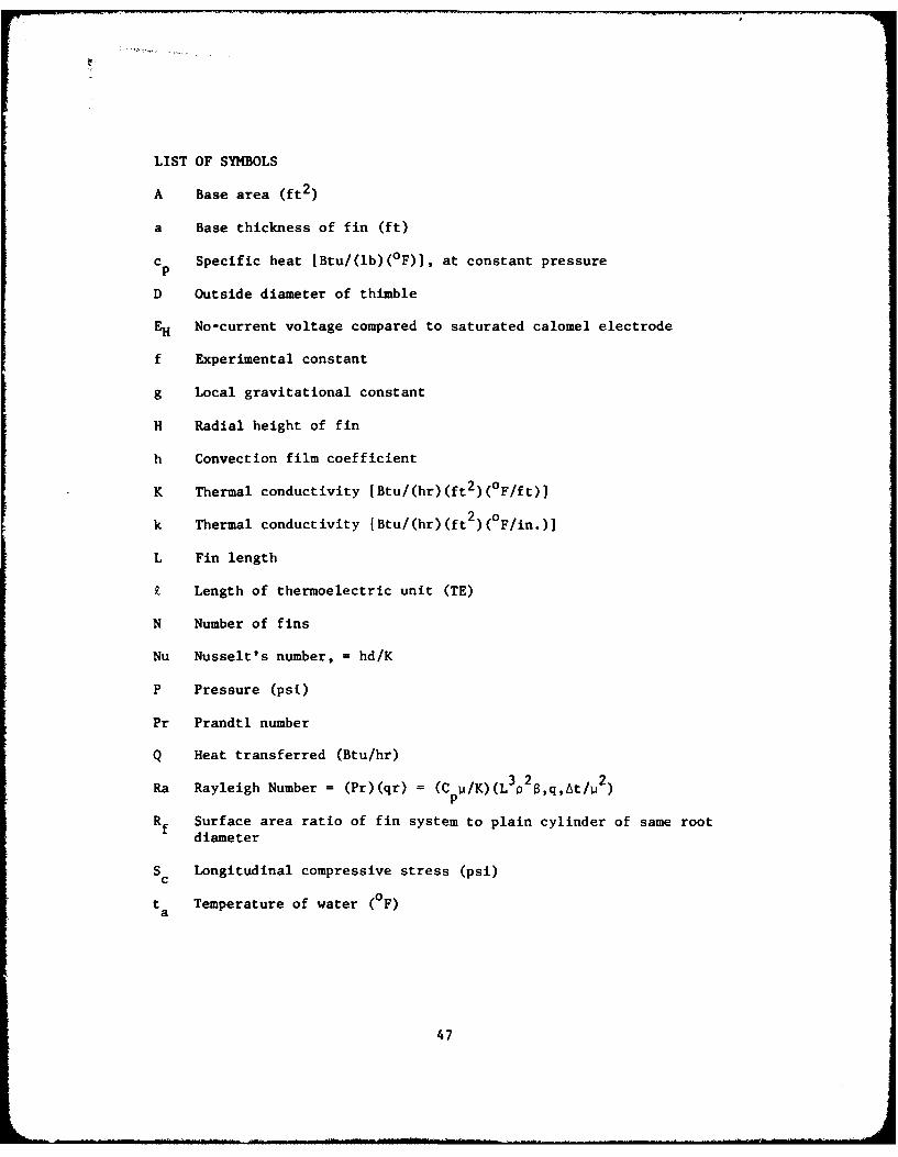
LIST OF SYMBOLS
A Base area (ft2 )
a Base thickness of fin (ft)
c Specific heat [Btu/(lb)(°F)], at constant pressurep
D Outside diameter of thimble
EH No-current voltage compared to saturated calomel electrode
f Experimental constant
g Local gravitational constant
H Radial height of fin
h Convection film coefficient
K Thermal conductivity [Btu/(hr)(ft 2 )(0 F/ft)J
k Thermal conductivity [Btu/(hr)(ft2)(F/in.)]
L Fin length
£ Length of thermoelectric unit (TE)
N Number of fins
Nu Nusselt's number, = hd/K
P Pressure (psi)
Pr Prandtl number
Q Heat transferred (Btu/hr)
3 2 2Ra Rayleigh Number - (Pr)(qr) = (C u/K)(L p 8,q,At/u 2 )p
Rf Surface area ratio of fin system to plain cylinder of same root
diameter
S Longitudinal compressive stress (psi)C
t Temperature of water (0F)a
47

tb Temperature of thimble base, Figure 2 (OF)
t Temperature of surface thermoelectric unit (OF)m
t Water temperaturew
t Ambient water temperaturewa
x Dimension in direction of heat flow
B Thermal coefficient of expansion of seawater (F)
At Temperature difference, metal surface to water (0F)
vi Viscosity, lb/(ft)(hr)
3p Density of seawater (lb/ft 3 )
48