Embed Size (px)
Citation preview
Heat transfer enhancement accompanyingpressure-loss reduction with winglet-type vortex generators
for fin-tube heat exchangers
K. Torii *, K.M. Kwak, K. Nishino
Department of Mechanical Engineering, Yokohama National University, 79-5 Tokiwadai, Hodogaya-ku, Yokohama 240-8501, Japan
Received 5 September 2001; received in revised form 6 February 2002
Abstract
This paper proposes a novel technique that can augment heat transfer but nevertheless can reduce pressure-loss in a
fin-tube heat exchanger with circular tubes in a relatively low Reynolds number flow, by deploying delta winglet-type
vortex generators. The winglets are placed with a heretofore-unused orientation for the purpose of augmentation of
heat transfer. This orientation is called as ‘‘common flow up’’ configuration. The proposed configuration causes sig-
nificant separation delay, reduces form drag, and removes the zone of poor heat transfer from the near-wake of the
tubes. This enhancement strategy has been successfully verified by experiments in the proposed configuration. In case of
staggered tube banks, the heat transfer was augmented by 30% to 10%, and yet the pressure loss was reduced by 55% to
34% for the Reynolds number (based on two times channel height) ranging from 350 to 2100, when the present winglets
were added. In case of in-line tube banks, these were found to be 20% to 10% augmentation, and 15% to 8% reduction,
respectively. � 2002 Published by Elsevier Science Ltd.
1. Introduction
Fin-tube heat exchangers are employed in a wide
variety of engineering applications, for example, in a
geothermal, fossil, process plant and air-conditioning,
etc. It is well known that most of the thermal resistance
is on the fin-side in such heat exchangers. In order to
enhance fin-side heat transfer between the fin and the gas
flow, one way is to use vortex generators to produce
longitudinal vortices inducing strong swirling motion
that serves to bring about enhancement of heat transfer
at a modest expense of the additional pressure-loss.
Fiebig et al. [1] investigated experimentally the influence
of delta winglet position on the fin surface having single
tube, by punching a pair of vortex generators ahead and
behind the tube, and found an increase of local heat
transfer coefficient up to 100% and mean heat transfer
coefficient up to 20% at the optimum winglet position,
immediately behind tube, for the Reynolds number
ranging from 2000 to 5000 based on fin pitch, H. They
also observed a reduction of 10% in the pressure loss,
and explained as the delayed separation on the tube due
to longitudinal vortices generated by the vortex gener-
ator which introduces high momentum fluid into the
wake region behind the tube. Fiebig and his group [2]
extended experimentally the influence of the winglet
vortex generators in fin-tube banks with three circular-
tube rows in the streamwise direction. In their chosen
geometry, the mean heat transfer coefficient increased by
55% to 65% for the inline tube arrangement, and by 9%
for the staggered tube arrangement, and, the corre-
sponding increases of pressure loss were 20% to 45%,
and 3%, respectively. Biswas et al. [3] revealed numeri-
cally significant heat transfer enhancement immediately
downstream of the tube in channel with built-in circular
tube and a pair of delta winglet vortex generator. Their
results show that longitudinal vortices generated by the
winglets placed in the wake enhance the local heat
transfer by 240%. A recent progress in vortex-induced
air-side heat transfer enhancement for fin-tube heat ex-
changers was reviewed in detail [4–6].
International Journal of Heat and Mass Transfer 45 (2002) 3795–3801www.elsevier.com/locate/ijhmt
*Corresponding author. Tel.: +81-45-339-3882; fax: +81-45-
331-6593.
E-mail address: [email protected] (K. Torii).
0017-9310/02/$ - see front matter � 2002 Published by Elsevier Science Ltd.
PII: S0017-9310 (02 )00080-7
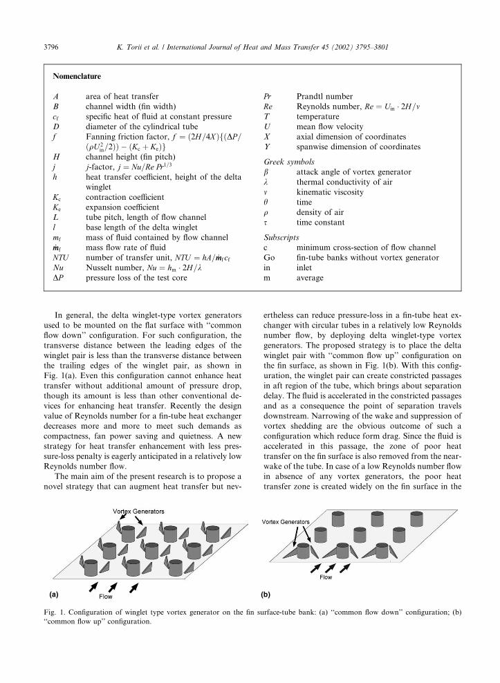
In general, the delta winglet-type vortex generators
used to be mounted on the flat surface with ‘‘common
flow down’’ configuration. For such configuration, the
transverse distance between the leading edges of the
winglet pair is less than the transverse distance between
the trailing edges of the winglet pair, as shown in
Fig. 1(a). Even this configuration cannot enhance heat
transfer without additional amount of pressure drop,
though its amount is less than other conventional de-
vices for enhancing heat transfer. Recently the design
value of Reynolds number for a fin-tube heat exchanger
decreases more and more to meet such demands as
compactness, fan power saving and quietness. A new
strategy for heat transfer enhancement with less pres-
sure-loss penalty is eagerly anticipated in a relatively low
Reynolds number flow.
The main aim of the present research is to propose a
novel strategy that can augment heat transfer but nev-
ertheless can reduce pressure-loss in a fin-tube heat ex-
changer with circular tubes in a relatively low Reynolds
number flow, by deploying delta winglet-type vortex
generators. The proposed strategy is to place the delta
winglet pair with ‘‘common flow up’’ configuration on
the fin surface, as shown in Fig. 1(b). With this config-
uration, the winglet pair can create constricted passages
in aft region of the tube, which brings about separation
delay. The fluid is accelerated in the constricted passages
and as a consequence the point of separation travels
downstream. Narrowing of the wake and suppression of
vortex shedding are the obvious outcome of such a
configuration which reduce form drag. Since the fluid is
accelerated in this passage, the zone of poor heat
transfer on the fin surface is also removed from the near-
wake of the tube. In case of a low Reynolds number flow
in absence of any vortex generators, the poor heat
transfer zone is created widely on the fin surface in the
Nomenclature
A area of heat transfer
B channel width (fin width)
cf specific heat of fluid at constant pressure
D diameter of the cylindrical tube
f Fanning friction factor, f ¼ ð2H=4X ÞfðDP=ðqU 2
in=2ÞÞ � ðKc þ KeÞgH channel height (fin pitch)
j j-factor, j ¼ Nu=Re Pr1=3
h heat transfer coefficient, height of the delta
winglet
Kc contraction coefficient
Ke expansion coefficient
L tube pitch, length of flow channel
l base length of the delta winglet
mf mass of fluid contained by flow channel
_mmf mass flow rate of fluid
NTU number of transfer unit, NTU ¼ hA= _mmfcfNu Nusselt number, Nu ¼ hm � 2H=kDP pressure loss of the test core
Pr Prandtl number
Re Reynolds number, Re ¼ Uin � 2H=mT temperature
U mean flow velocity
X axial dimension of coordinates
Y spanwise dimension of coordinates
Greek symbols
b attack angle of vortex generator
k thermal conductivity of air
m kinematic viscosity
h time
q density of air
s time constant
Subscripts
c minimum cross-section of flow channel
Go fin-tube banks without vortex generator
in inlet
m average
Fig. 1. Configuration of winglet type vortex generator on the fin surface-tube bank: (a) ‘‘common flow down’’ configuration; (b)
‘‘common flow up’’ configuration.
3796 K. Torii et al. / International Journal of Heat and Mass Transfer 45 (2002) 3795–3801
near-wake of the tube and may extend far downstream,
even to the next row of the tube bank. Hence it is ex-
pected that the present strategy may be more effective
for a lower Reynolds number flow.
2. Experimental method and procedure
2.1. Experimental apparatus
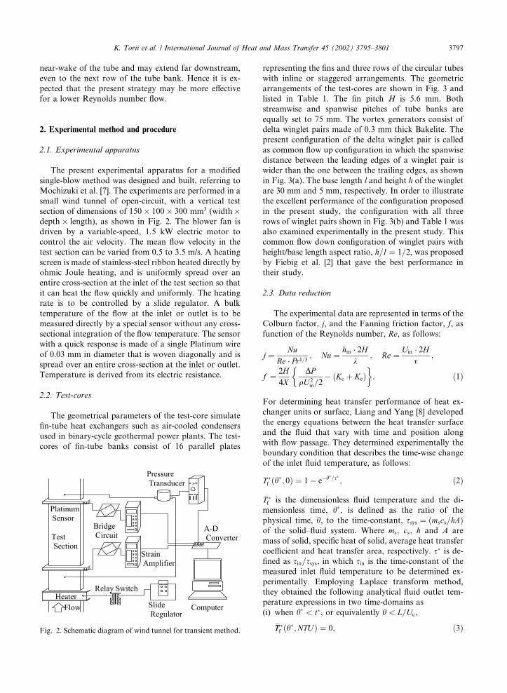
The present experimental apparatus for a modified
single-blow method was designed and built, referring to
Mochizuki et al. [7]. The experiments are performed in a
small wind tunnel of open-circuit, with a vertical test
section of dimensions of 150 100 300 mm3 (widthdepth length), as shown in Fig. 2. The blower fan is
driven by a variable-speed, 1.5 kW electric motor to
control the air velocity. The mean flow velocity in the
test section can be varied from 0.5 to 3.5 m/s. A heating
screen is made of stainless-steel ribbon heated directly by
ohmic Joule heating, and is uniformly spread over an
entire cross-section at the inlet of the test section so that
it can heat the flow quickly and uniformly. The heating
rate is to be controlled by a slide regulator. A bulk
temperature of the flow at the inlet or outlet is to be
measured directly by a special sensor without any cross-
sectional integration of the flow temperature. The sensor
with a quick response is made of a single Platinum wire
of 0.03 mm in diameter that is woven diagonally and is
spread over an entire cross-section at the inlet or outlet.
Temperature is derived from its electric resistance.
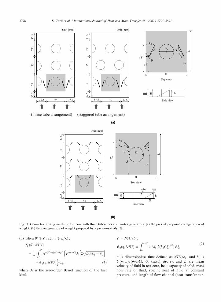
2.2. Test-cores
The geometrical parameters of the test-core simulate
fin-tube heat exchangers such as air-cooled condensers
used in binary-cycle geothermal power plants. The test-
cores of fin-tube banks consist of 16 parallel plates
representing the fins and three rows of the circular tubes
with inline or staggered arrangements. The geometric
arrangements of the test-cores are shown in Fig. 3 and
listed in Table 1. The fin pitch H is 5.6 mm. Both
streamwise and spanwise pitches of tube banks are
equally set to 75 mm. The vortex generators consist of
delta winglet pairs made of 0.3 mm thick Bakelite. The
present configuration of the delta winglet pair is called
as common flow up configuration in which the spanwise
distance between the leading edges of a winglet pair is
wider than the one between the trailing edges, as shown
in Fig. 3(a). The base length l and height h of the winglet
are 30 mm and 5 mm, respectively. In order to illustrate
the excellent performance of the configuration proposed
in the present study, the configuration with all three
rows of winglet pairs shown in Fig. 3(b) and Table 1 was
also examined experimentally in the present study. This
common flow down configuration of winglet pairs with
height/base length aspect ratio, h=l ¼ 1=2, was proposedby Fiebig et al. [2] that gave the best performance in
their study.
2.3. Data reduction
The experimental data are represented in terms of the
Colburn factor, j, and the Fanning friction factor, f, as
function of the Reynolds number, Re, as follows:
j ¼ NuRe � Pr1=3 ; Nu ¼ hm � 2H
k; Re ¼ Uin � 2H
m;
f ¼ 2H4X
DPqU 2
in=2
�� Kcð þ KeÞ
�: ð1Þ
For determining heat transfer performance of heat ex-
changer units or surface, Liang and Yang [8] developed
the energy equations between the heat transfer surface
and the fluid that vary with time and position along
with flow passage. They determined experimentally the
boundary condition that describes the time-wise change
of the inlet fluid temperature, as follows:
T f ðh
; 0Þ ¼ 1� e�h=s ; ð2Þ
T f is the dimensionless fluid temperature and the di-
mensionless time, h, is defined as the ratio of the
physical time, h, to the time-constant, ssys ¼ ðmscs=hAÞof the solid–fluid system. Where ms; cs; h and A are
mass of solid, specific heat of solid, average heat transfer
coefficient and heat transfer area, respectively. s is de-fined as sin=ssys, in which sin is the time-constant of themeasured inlet fluid temperature to be determined ex-
perimentally. Employing Laplace transform method,
they obtained the following analytical fluid outlet tem-
perature expressions in two time-domains as
(i) when h < t, or equivalently h < L=Uc,
�TT f ðh
;NTUÞ ¼ 0; ð3ÞFig. 2. Schematic diagram of wind tunnel for transient method.
K. Torii et al. / International Journal of Heat and Mass Transfer 45 (2002) 3795–3801 3797
(ii) when h P t, i.e., h PL=Uc,
�TT f ðh
;NTUÞ
¼ 1
s
Z h
te�ðh�gÞ=s�b2 t e�ðg�tÞJ0 2
ffiffiffiffiffiffiffiffiffiffiffiffiffiffiffiffiffiffiffiffiffiffiffib2tðg � tÞ
ph in
þ w2ðg;NTUÞodg; ð4Þ
where J0 is the zero-order Bessel function of the first
kind,
t ¼ NTU=b1;
w2ðg;NTUÞ ¼Z g�t
0
e�nJ0½2ðb2tnÞ1=2� dn;ð5Þ
t is dimensionless time defined as NTU=b1, and b1 is
UðmscsÞ=ð _mmfcfLÞ. U ; ðmscsÞ; _mmf ; cf ; and L are mean
velocity of fluid in test core, heat capacity of solid, mass
flow rate of fluid, specific heat of fluid at constant
pressure, and length of flow channel (heat transfer sur-
Fig. 3. Geometric arrangements of test core with three tube-rows and vortex generators: (a) the present proposed configuration of
winglet; (b) the configuration of winglet proposed by a previous study [2].
3798 K. Torii et al. / International Journal of Heat and Mass Transfer 45 (2002) 3795–3801
face), respectively. b2 is heat capacity ratio between the
solid and the fluid defined as fðmscsÞ=ðmfcfÞg. Uc is mean
velocity based on minimum cross-sectional area, Ac; f;and g are dummy variable.
Firstly, a measured inlet air temperature is fitted with
Eq. (2) at three periods of time, h1, h2 ¼ 2h1, h3 ¼ 3h1, todetermine the values of the final steady inlet tempera-
ture, Tfinal, and sin. The inlet temperature is recorded
with a time step of 0.02 s for 1500 steps corresponding to
30 s after it starts rising. During the early period of time
steps it cannot follow Eq. (2) but shows a response with
a time lag, h0. In order to avoid this period and find the
appropriate period automatically, the following proce-
dure is taken.
The time, h1, is assumed to be 3 s to first approxi-
mation and is increased time-step by time-step until the
measured inlet temperatures can be fitted well with Eq.
(2) without introducing the time lag, h0, within one time
step. Hence the measured inlet temperatures, Tf 1, Tf 2,and Tf 3, at h1; h2 ¼ 2h1, and h3 ¼ 3h1, respectively, sat-isfy Eq. (2) and give the final temperature Tfinal, and the
time constant sin by the following equations as
Tfinal ¼ Tf 1 þ ðTfinal � Tf 2ÞTfinal � Tf2Tfinal � Tf3
�ðh2�h1Þ=ðh3�h2Þ
;
sin ¼ ðh2 � h1Þ lnTfinal � Tf 1Tfinal � Tf 2
� ��:
ð6Þ
The obtained value of sin ranges from 6.6 to 23 s, and the
values of h1=sin were found to be 0.16–0.53 for the
present experiments.
By substituting the values of sin; Tfinal, geometricaland physical properties of flow channel and heat transfer
surfaces, and an assumed value of heat transfer coeffi-
cient h, into the theoretical equation (4), the exit fluid
temperature, Tf ;thnal-at exit, is calculated and is then com-
pared with the measured value of fluid temperature at
the exit, Tf ;expt--at exit. If the difference between Tf ;thit-at exitand Tf ;expt--at exit is within an acceptable degree of accu-
racy less than 0.1%, then the assumed value of h is
considered to be correct. However, if the theory fails to
agree with the measured response, a new value of h is
picked and the procedure is repeated until the correct
value of h is found. These calculations are performed to
get the average value of the heat transfer coefficient, h, at
10 points of time in the neighborhood of sin for each
experiment. The assumption that a temperature gradient
is negligible inside the fin is acceptable since Biot num-
ber, hmd=2kf , based on the measured, hm, and fin
thickness, d, is order of 10�6.
3. Experimental results and discussion
The Reynolds number, Re ¼ ðUin2HÞ=m, based on thehydraulic diameter of the test-core inlet varies from 350
to 2400. The average heat transfer coefficient of the test-
core is defined by using its heat transfer area excluding
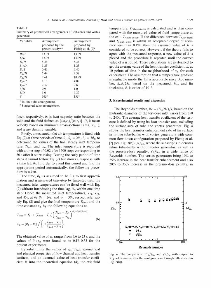
the surface area of tube and vortex generators. Fig. 4
shows the heat transfer enhancement rate of fin surface
in in-line tube-banks with vortex generators with com-
mon flow down configuration proposed by Fiebig et al.
[2] (see Fig. 3(b)), j=jGo, where the subscript Go denotes
inline tube-banks without vortex generator, as well as
the pressure-loss penalty, f =fGo, in a wide range of
Reynolds number. The vortex generators bring 10% to
25% increase in the heat transfer enhancement and also
20% to 35% increase in the pressure-loss penalty, in
Fig. 4. The comparison of j=jGo and f =fGo with respect to
Reynolds number (for the configuration of winglet illustrated in
Fig. 3(b)).
Table 1
Summary of geometrical arrangements of test-cores and vortex
generators
Variables Arrangement
proposed by the
present studya ;b
Arrangement
proposed by
Fiebig et al. [2]a
B=H 13.39 13.39
L=H 13.39 13.39
D=H 5.36 5.36
L1=D 1.25 1.25
D=B 0.40 0.40
XA=H 2.44 9.38
XB=H 7.61 10.79
YA=H 1.19 4.02
YB=H 2.57 2.60
h=H 0.9 1.0
l=D 1.0 0.37
b 165� 135�a In-line tube arrangement.b Staggered tube arrangement.
K. Torii et al. / International Journal of Heat and Mass Transfer 45 (2002) 3795–3801 3799
comparison with tube-banks without vortex generators.
Although it is attractive to the heat transfer enhance-
ment, this configuration brings about the pressure loss
penalty more than the heat transfer enhancement, as
shown in Fig. 4. In addition, this configuration is found
to be not so effective in heat transfer enhancement in a
low Reynolds number as in a high Reynolds number
flow studied by Fiebig et al. [2]. It should be noted that
many heat exchangers including geothermal air-cooled
condensers operate at such a low Reynolds number as
below 1000. It suggests that heat transfer enhancement
in a laminar flow of low Reynolds number necessitates
an innovative concept being entirely different from the
conventional concept effective to a high Reynolds
number flow. In order to understand the physics, our
collaborators, O’Brien and Sohal [9] investigated the
local heat transfer in a single passage of narrow rect-
angular duct fitted with a circular tube and/or a delta
winglet pair using imaging infrared camera. The location
and aspect ratio of the winglets were the same as the
present study shown in Fig. 3(b). As for the spanwise
variation, they showed that the vortex generators re-
duced the size of wake region behind tube, but the heat
transfer directly downstream of the tube were rather
slightly reduced for the fin-tube with winglets, being
compared to the one without winglets. According to
their study, heat transfer is strongly enhanced down-
stream of winglet pair but indistinctly in the wake region
behind the tube.
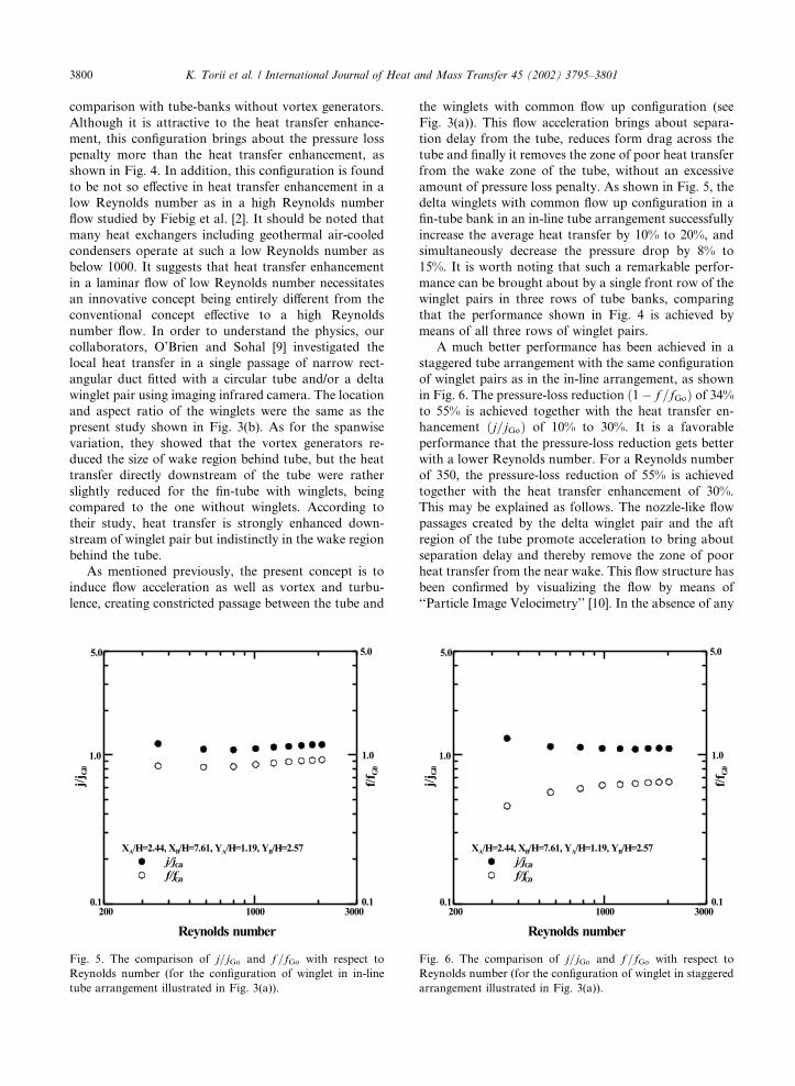
As mentioned previously, the present concept is to
induce flow acceleration as well as vortex and turbu-
lence, creating constricted passage between the tube and
the winglets with common flow up configuration (see
Fig. 3(a)). This flow acceleration brings about separa-
tion delay from the tube, reduces form drag across the
tube and finally it removes the zone of poor heat transfer
from the wake zone of the tube, without an excessive
amount of pressure loss penalty. As shown in Fig. 5, the
delta winglets with common flow up configuration in a
fin-tube bank in an in-line tube arrangement successfully
increase the average heat transfer by 10% to 20%, and
simultaneously decrease the pressure drop by 8% to
15%. It is worth noting that such a remarkable perfor-
mance can be brought about by a single front row of the
winglet pairs in three rows of tube banks, comparing
that the performance shown in Fig. 4 is achieved by
means of all three rows of winglet pairs.
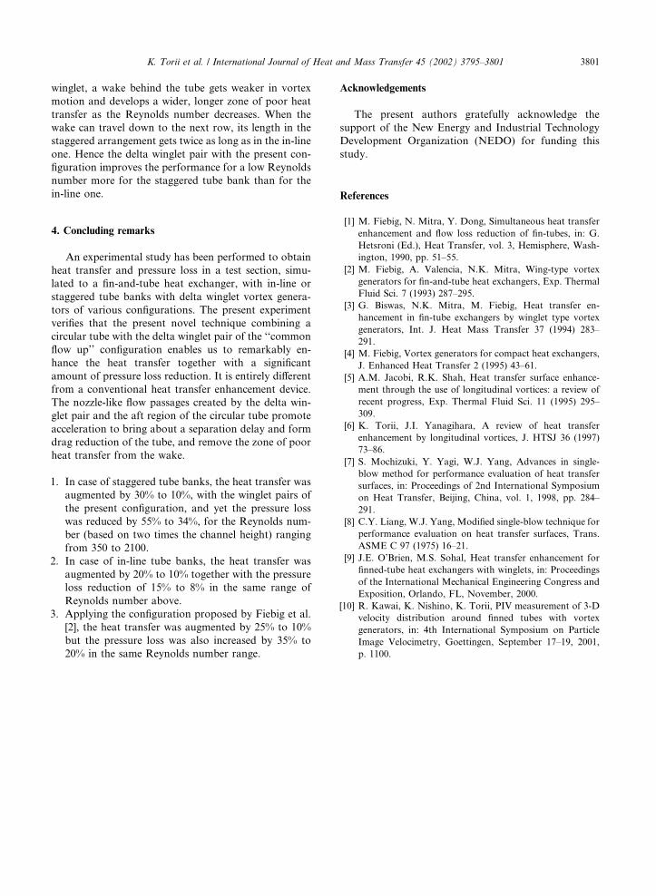
A much better performance has been achieved in a
staggered tube arrangement with the same configuration
of winglet pairs as in the in-line arrangement, as shown
in Fig. 6. The pressure-loss reduction ð1� f =fGoÞ of 34%to 55% is achieved together with the heat transfer en-
hancement ðj=jGoÞ of 10% to 30%. It is a favorable
performance that the pressure-loss reduction gets better
with a lower Reynolds number. For a Reynolds number
of 350, the pressure-loss reduction of 55% is achieved
together with the heat transfer enhancement of 30%.
This may be explained as follows. The nozzle-like flow
passages created by the delta winglet pair and the aft
region of the tube promote acceleration to bring about
separation delay and thereby remove the zone of poor
heat transfer from the near wake. This flow structure has
been confirmed by visualizing the flow by means of
‘‘Particle Image Velocimetry’’ [10]. In the absence of any
Fig. 5. The comparison of j=jGo and f =fGo with respect to
Reynolds number (for the configuration of winglet in in-line
tube arrangement illustrated in Fig. 3(a)).
Fig. 6. The comparison of j=jGo and f=fGo with respect to
Reynolds number (for the configuration of winglet in staggered
arrangement illustrated in Fig. 3(a)).
3800 K. Torii et al. / International Journal of Heat and Mass Transfer 45 (2002) 3795–3801
winglet, a wake behind the tube gets weaker in vortex
motion and develops a wider, longer zone of poor heat
transfer as the Reynolds number decreases. When the
wake can travel down to the next row, its length in the
staggered arrangement gets twice as long as in the in-line
one. Hence the delta winglet pair with the present con-
figuration improves the performance for a low Reynolds
number more for the staggered tube bank than for the
in-line one.
4. Concluding remarks
An experimental study has been performed to obtain
heat transfer and pressure loss in a test section, simu-
lated to a fin-and-tube heat exchanger, with in-line or
staggered tube banks with delta winglet vortex genera-
tors of various configurations. The present experiment
verifies that the present novel technique combining a
circular tube with the delta winglet pair of the ‘‘common
flow up’’ configuration enables us to remarkably en-
hance the heat transfer together with a significant
amount of pressure loss reduction. It is entirely different
from a conventional heat transfer enhancement device.
The nozzle-like flow passages created by the delta win-
glet pair and the aft region of the circular tube promote
acceleration to bring about a separation delay and form
drag reduction of the tube, and remove the zone of poor
heat transfer from the wake.
1. In case of staggered tube banks, the heat transfer was
augmented by 30% to 10%, with the winglet pairs of
the present configuration, and yet the pressure loss
was reduced by 55% to 34%, for the Reynolds num-
ber (based on two times the channel height) ranging
from 350 to 2100.
2. In case of in-line tube banks, the heat transfer was
augmented by 20% to 10% together with the pressure
loss reduction of 15% to 8% in the same range of
Reynolds number above.
3. Applying the configuration proposed by Fiebig et al.
[2], the heat transfer was augmented by 25% to 10%
but the pressure loss was also increased by 35% to
20% in the same Reynolds number range.
Acknowledgements
The present authors gratefully acknowledge the
support of the New Energy and Industrial Technology
Development Organization (NEDO) for funding this
study.
References
[1] M. Fiebig, N. Mitra, Y. Dong, Simultaneous heat transfer
enhancement and flow loss reduction of fin-tubes, in: G.
Hetsroni (Ed.), Heat Transfer, vol. 3, Hemisphere, Wash-
ington, 1990, pp. 51–55.
[2] M. Fiebig, A. Valencia, N.K. Mitra, Wing-type vortex
generators for fin-and-tube heat exchangers, Exp. Thermal
Fluid Sci. 7 (1993) 287–295.
[3] G. Biswas, N.K. Mitra, M. Fiebig, Heat transfer en-
hancement in fin-tube exchangers by winglet type vortex
generators, Int. J. Heat Mass Transfer 37 (1994) 283–
291.
[4] M. Fiebig, Vortex generators for compact heat exchangers,
J. Enhanced Heat Transfer 2 (1995) 43–61.
[5] A.M. Jacobi, R.K. Shah, Heat transfer surface enhance-
ment through the use of longitudinal vortices: a review of
recent progress, Exp. Thermal Fluid Sci. 11 (1995) 295–
309.
[6] K. Torii, J.I. Yanagihara, A review of heat transfer
enhancement by longitudinal vortices, J. HTSJ 36 (1997)
73–86.
[7] S. Mochizuki, Y. Yagi, W.J. Yang, Advances in single-
blow method for performance evaluation of heat transfer
surfaces, in: Proceedings of 2nd International Symposium
on Heat Transfer, Beijing, China, vol. 1, 1998, pp. 284–
291.
[8] C.Y. Liang, W.J. Yang, Modified single-blow technique for
performance evaluation on heat transfer surfaces, Trans.
ASME C 97 (1975) 16–21.
[9] J.E. O’Brien, M.S. Sohal, Heat transfer enhancement for
finned-tube heat exchangers with winglets, in: Proceedings
of the International Mechanical Engineering Congress and
Exposition, Orlando, FL, November, 2000.
[10] R. Kawai, K. Nishino, K. Torii, PIV measurement of 3-D
velocity distribution around finned tubes with vortex
generators, in: 4th International Symposium on Particle
Image Velocimetry, Goettingen, September 17–19, 2001,
p. 1100.
K. Torii et al. / International Journal of Heat and Mass Transfer 45 (2002) 3795–3801 3801