Embed Size (px)
Citation preview

6th European Conference on Computational Mechanics (ECCM 6)7th European Conference on Computational Fluid Dynamics (ECFD 7)
1115 June 2018, Glasgow, UK
HEAT TRANSFER MAXIMIZATION IN A THREEDIMENSIONAL CONDUCTIVE DIFFERENTIALLY
HEATED CAVITY BY MEANS OF TOPOLOGYOPTIMIZATION
CLIO SAGLIETTI1, EDDIE WADBRO2, MARTIN BERGGREN2 ANDDAN S. HENNINGSON1
1 Linne FLOW Centre and Swedish e-Science Research Centre (SeRC), KTH MechanicsRoyal Institute of TechnologySE-114 28 Stockholm, Sweden
[email protected]@mech.kth.se
2 Department of Computing Science, Umea UniversitySE-901 87 Umea, Sweden
[email protected]@cs.umu.se
Key words: Topology optimization; Conjugate heat transfer; Three dimensional con-ductive differentially heated cavity; Natural convection; Heat sinks.
Abstract. The thermal performance of heat sinks is enhanced, in the present paper,by applying a material distribution topology optimization approach. We consider solidstructures enclosed in three dimensional steady-state conductive differentially heated cav-ities. The algorithm iteratively updates the geometry of a heat sink, relying on gradientinformation. The gradient information are computed using adjoint sensitivity methods,combined with high-order accuracy direct numerical simulations. A complete conjugatedproblem is solved, in which we describe the effect of the solid material on the surround-ing flow through the action of a Brinkman friction term in the Navier–Stokes equations,and we map the material distribution function onto the thermal conductivity and heatcapacity in the energy conservation equation. Additionally, advanced filtering techniquesare applied for enforcing a desired length scale to the solid structure. The success of themethod is presented with a thorough physical investigation of the optimal results, whichdeliver a substantial increase of the heat transfer.
1 INTRODUCTION
Optimization of natural convection cooling systems is a major engineering challenge ofthe present times. Because of their high reliability and durability, they can be employedfor many industrial applications. One of the most advanced techniques for optimizing suchsystems is to act on the topology of the heat sink, that is, how its geometry is connected,

Clio Saglietti, Eddie Wadbro, Martin Berggren and Dan S. Henningson
thus optimizing the thermal performance by canalizing the surrounding flow. Bendsøeand Kikuchi1 introduced a method for optimization of load carrying elastic structuresthat has become influential also for other applications,2 the material distribution topologyoptimization method. This approach aims to optimally distribute in space a compositematerial function. Each point of the domain is a degree of freedom, thus there are no apriori restriction on the optimal topology.
z x
y
Figure 1: Sketch of thecomputational domain (Ω:−0.5 ≤ x ≤ 0.5, −0.5 ≤y ≤ 0.5, and −0.5 ≤ z ≤ 0)and of the optimization do-main (in gray ΩO: −0.46 ≤x ≤ −0.25, −0.25 ≤ y ≤ 0.25,and −0.25 ≤ z ≤ 0). On thecold wall, Γ1 (in blue), the ob-jective function J is evalu-ated. Against the warm wall,Γ2 (in red), a solid box (inblack Ωs) connects the warmwall to the optimization do-main. The rest of the vol-ume is fluid (Ωf ). The de-sign function ρ may not varyin Ωf ∪ Ωs. Symmetry side,Γ3: green contour.
Optimization of simple conduction problems was the firstform of topology optimization for enhancing thermal perfor-mances.2 In the following years, more advanced studies haveincluded convection contributions. At the beginning, convec-tive effects were just treated as a boundary condition;3 later,the entire conjugate heat transfer has been considered. Thefirst attempts were limited to Stokes problems,4,5 but more re-cently, the feasibility of the method has been proven on Navier–Stokes problems.6–8 There are various ways of describing theembedded heat sink. One way is to use a level set function,9,10
another is the immersed boundary method.11 In the secondcase, the momentum conservation law is solved in the wholedomain, but the velocity is penalized inside the solid structureusing a Brinkman friction term.12 Moreover, the material dis-tribution function is also mapped to the thermal properties insolving the energy conservation law.13
In the present paper, we limit the study to heat sinksconfined inside a three dimensional steady-state conductivedifferentially heated cavity, in which the buoyancy (underBoussinesq approximation) drives a swirling laminar convec-tive flow.14 We measure the enhancement of the heat sinks’thermal performance by evaluating the heat flux through thecold side of the cavity. For identifying the optimized de-sign, the material distribution topology optimization methodis combined with high-order accuracy steady-state direct nu-merical simulations (DNS) computed with the spectral elementcode Nek500015 and the BoostConv algorithm.16 At each com-putational point in the domain, a material indicator functionρ can describe the fluid (ρ = 1) or the solid (ρ = 0). The design function is allowed toattain values in the continuum ρ ∈ [0, 1] in order to allow for gradient-based optimizationalgorithms. Penalty together with advanced filtering techniques17 are employed in orderto promote sharp interfaces and at the same time avoid small design features and meshdependencies.
The paper is organized as follows. The problem is presented in Section 2 by outliningthe governing equations and explaining how they are numerically solved. In Section 3the filtering is described and in Section 4 the geometrical specification is given and theoptimization algorithm is described. A thorough physical interpretation of the results
2

Clio Saglietti, Eddie Wadbro, Martin Berggren and Dan S. Henningson
follows in Section 5, just before the conclusions.
2 PROBLEM PRESENTATION
The enhancement of the thermal performance of heat sinks is the primary focus of thepresent paper. We rely on the high-order accurate spectral element code nek5000 togetherwith a material-distribution topology optimization algorithm to numerically generate aneffective geometry for a vertical heat sink enclosed in a conductive differentially heatedcavity. The heat sink, attached to the warm wall of the cavity, is optimized for maximizingthe heat transfer through the cavity, that is, the measure of the heat flux through thecold wall.
2.1 Physical specification
We describe the conjugate heat transfer problem originated by the interaction betweenan ideal Newtonian fluid and a solid structure. The incompressible flow under study isdriven by natural convection (buoyancy force) and cools down the heat sink attachedto the warm wall of the cavity. We limit the study to steady state conditions that arerepresentative of a flow without instabilities and turbulence. We solve thus the steadystate Navier–Stokes equations to evaluate the contribution of the thermal convection tothe overall heat transfer, and we solve the energy conservation equation in the wholedomain for computing the temperature distribution.
The chosen non-dimensionalization18 relies on the Rayleigh and the Prandtl numbers
Ra =ρ∗C∗fβ
∗|g∗|∆T ∗x∗3
µ∗K∗f, P r =
µ∗C∗fρ∗k∗f
, (1)
respectively, in which the reference length, velocity, temperature, pressure, and time are
x∗ref = L∗, u∗ref =k∗f√Ra
C∗fL∗ , θ∗ref = ∆T ∗, p∗ref = ρ∗u∗ref
2Pr, t∗ref =L∗
u∗ref
, (2)
respectively. Additionally, k∗ defines the thermal conductivity; C∗ the thermal heatcapacity (the subscript s and f indicate solid and fluid, respectively); ρ∗, µ∗, and β∗ arethe density, the viscosity, and the thermal expansion coefficient of the fluid, respectively.All dimensional variables are identified by a star, L∗ is the cavity length, ∆T ∗ is thetemperature difference with respect to the ambient, and eg = −g∗/|g∗| is the unit gravityvector. As the dimensionless governing equations
1
Pr(u · ∇)u− 1√
Ra∇2u +∇p− egθ + χ(ρ)u = 0,
C(ρ)(u · ∇)θ − 1√Ra∇ · k(ρ)∇θ = 0,
∇ · u = 0,
(3)
show, under the Boussinesq approximation, the flow is driven by temperature variations.Moreover, we model the effect of the solid structure on the fluid flow as the action of a
3

Clio Saglietti, Eddie Wadbro, Martin Berggren and Dan S. Henningson
Brinkman friction term12 in the momentum equations. The amplitude of the Brinkmanforce χ(ρ) has a direct dependence on the material indicator function ρ that is continuouslydefined in the whole domain (solid: ρ = 0; fluid: ρ = 1). The function ρ is, in turn,obtained from the design function ρ through the filtering operation described in Section 3.Also in the temperature equation, we rely on ρ for defining its coefficients,13 the adjustednon-dimensional heat capacity C(ρ) and the non-dimensional thermal conductivity k(ρ).The interpolation of the coefficients is done using SIMP-type functions:2
χ(ρ) = χ(1− ρ)p, C(ρ) = 1− (1− ρ)p, k(ρ) =
(kskf− 1
)(1− ρ)p , (4)
where p is the exponent that characterizes the steepness of the interpolation. The choiceof having an adjusted thermal heat capacity legitimates the use of the Brinkman frictionterm. Indeed, when using an immersed boundary method (IBM), there is inevitably asmall but nonzero velocity also in the solid.11 Since our analysis focuses on heat transferoptimization, we set to zero the dimensionless heat capacity coefficient in the solid regions(C(ρ) = 0, when ρ = 0) to eliminate unrealistic convection contributions.
Finally, we want to measure the the efficiency of the optimized geometry in termsof heat transfer maximization through the cavity. The Fourier law indicates that Φ∗ =−k∗∇∗θ∗ ·n is the heat flux density through a surface. Here, k∗ is the thermal conductivityand the unit normal vector n indicates the orientation of the surface. The non-dimensionalheat flux is thus computed as Φ = k∗/k∗f∇θ · n.
2.2 Numerical specification
To numerically solve the governing equations (3), we rely on the spectral-element solverNek5000.15 The code requires the computational domain to be divided in non-overlappingdeformable quadrilaterals, in each of which a tensor product of Legendre polynomialsof order N spans the solution. Additionally, the solution is required to satisfy a C0
continuity condition across the elements. At the N+1 Gauss–Lobatto–Legendre (GLL)quadrature nodes on each element, the velocity u and the temperature θ are evaluatedwith Lagrangian interpolants.19 To guarantee skew symmetry of the advection term inthe momentum conservation equations, over-integration is applied. Moreover, to suppressspurious pressure modes, the pressure p is evaluated as a Lagrangian interpolant of lowerorder (N − 2) on a staggered grid (PN − PN−2 method20).
Moreover, to compute the steady-state solution of the governing equations, a timemarching scheme with enhanced convergence is used, the BoostConv method.16 Thealgorithm treats the time evolution of Equation (3) as an iterative algorithm for solvinggeneral large-scale linear systems. A continuously adapting basis of size N is defined,which spans the rn = [u; θ]n+1 − [u; θ]n residuals in time. With this basis, a least-square problem is solved to obtain a modified residual ξn, which is used to recompute[u; θ]n+1 = [u; θ]n + ξnand thus minimize the residual at iteration n+ 1.21
4

Clio Saglietti, Eddie Wadbro, Martin Berggren and Dan S. Henningson
3 DESIGN DEFINITION
The material indicator function ρ, whose use has been described in Section 2.1, is de-fined indirectly through nonlinear filtering of an auxiliary design variable ρ. In particular,for the present study we have considered density filters to impose a length scale R to theoptimized structures.22,23 A cascade of so-called fW-mean nonlinear filters17 is used to ob-tain an approximation of the so-called open operation from mathematical morphology.24
We start by considering the classic linear filter25 FL, defined as the weighted convolutionof two functions
FL(ρ)(x′) =(ρ ∗ ω)(x′)
W (x′)=
∫Ωρ(x)ω(|x− x′|) dx
W (x′), where
W (x′) =
∫Ω
ω(|x− x′|) dx, ω =
23
(32− |r|
)2if 1
2≤ |r| ≤ 3
2
1− 43|r|2 if 0 ≤ |r| < 1
2
, r =3
2
|x− x′|R
.
(5)To perform the open filter operation using fW -mean nonlinear filters, we use first a FEerode operation, followed by a FD dilate one,
FE(ρ) = f−1E
(FL(fE ρ
)), FD(ρ) = f−1
D (FL(fD ρ
)), (6)
where indicates a composition of two function, as (fE ρ)(x) = fE(ρ(x)). The functionsfE and fD, together with their inverse f−1
E and f−1D are, for s ∈ <, defined as
fE(s) =1
s+ β, fD(s) =
1
1− s+ β, f−1
E (s) =1
s− β, f−1
D (s) = 1− 1
s+ β, (7)
respectively, with parameter β > 0. We define our composite nonlinear filter as
ρ = F (ρ) = FD(FE(ρ)
); (8)
that is, we first compute the composition of fE with the design variable ρ, then we applythe linear filter FL to the result, in order to obtain ρ′ = FL(fE ρ). Successively, wecompose the inverse function f−1
E with ρ′ to obtain ρ′′ = FE(ρ), which is composed withfD to become the input of a second linear filter operation FL (ρ′′′ = FL
(fD ρ′′
)). At last,
we compose the inverse function f−1D with ρ′′′ to obtain ρ = FD(ρ′′).
4 SETUP PRESENTATION
We measure the enhanced performance of the optimized heat sink by evaluating theheat flux through the cold wall of the cavity (Γ1), that is our objective function
J =
∫Γ1
−k∗
k∗f∇θ · n dΓ. (9)
5

Clio Saglietti, Eddie Wadbro, Martin Berggren and Dan S. Henningson
4.1 Geometry specification
We impose no slip boundary conditions on all external walls. For the temperature,we impose on the vertical walls uniform Dirichlet boundary conditions (cold θ = 0 atx = 0.5, Γ1, and θ = 1 at x = −0.5, Γ2). At z = 0 we define a symmetry plane, Γ3. Allother external walls are by definition conductive (i.e. a Dirichlet boundary condition withdecreasing temperature θ = 0.5 − x). The gravity acts in the negative vertical direction(−y), and due to the buoyancy force, the horizontal temperature gradient imposed by theboundary conditions (along x) generates a clockwise flow rotation.
In order to obtain structures that act as heat sinks, we consider the optimization domain(ΩO) to be a subset of the computational domain (−0.46 ≤ x ≤ −0.25, −0.25 ≤ y ≤ 0.25,and −0.25 ≤ z ≤ 0, see Fig. 1 for more details). Outside the optimization domain thedesign function ρ is forced to be solid in all the collocation points inside the black boxlocated against the warm wall (Ωs), and fluid everywhere else (Ωf ).
4.2 Optimization problem
We want to optimize ρ ∈ A = ρ ∈ L∞(Ω) | 0 ≤ ρ ≤ 1, ρ|Ωs ≡ 0, ρ|Ωf≡ 1 for
maximizing J (see Eq. (9)). The constraints are the governing equations (3), the filteroperation (8), the boundary conditions, and the maximal amount of solid volume
minρ∈A
−J ,
s.t.1
Pr(u · ∇)u− 1√
Ra∇2u +∇p− egθ + χ(ρ)u = 0 in Ω,
C(ρ)(u · ∇)θ − 1√Ra∇ · k(ρ)∇θ = 0 in Ω,
∇ · u = 0 in Ω,
ρ− F (ρ) = 0 in Ω,
u = 0 on Γ \ Γ3, ∇u · n = 0 on Γ3,
θ = 0 on Γ1, θ = 1 on Γ2,
∇θ · n = 0 on Γ3, θ = 0.5− x on Γ \ (Γ1 ∪ Γ2 ∪ Γ3),∫Ω
(1− ρ) dΩ ≤ Vmax.
(10)
To solve (10), we rely on the optimization algorithm MMA26 together with adjoint-basedgradient calculations.7
In detail, we first define an initial design ρ and then iteratively solve the followingalgorithm until convergence:
• Compute ρ = F (ρ) (Eq. 8);
• Map ρ to the coefficients k, C, χ (Eq. 4);
• Solve the governing equations (Eq. 3);
6

Clio Saglietti, Eddie Wadbro, Martin Berggren and Dan S. Henningson
• Solve the adjoint problem
1
Pr(−(u · ∇u†) + (∇u)T · u†)− 1√
Ra∇2u† −∇p† + C(∇θ)θ† + χu† = 0,
−eg · u† − C(u · ∇)θ† − 1√Ra∇ · k∇θ†= 0,
∇ · u†= 0;
u† = 0 on Γ \ Γ3, ∇u† · n = 0 on Γ3,
θ† =√Ra on Γ2, ∇θ† · n = 0 on Γ3, θ† = 0 on Γ \ Γ3 ∪ Γ2,
(11)
• Compute the derivative of the objective function with respect to ρ:
ρ† = p(ρ−1)p−1θ†(u·∇)θ+p(kskf−1)(1−ρ)p−1 1√
Ra∇θ†·∇θ+pχ(1−ρ)p−1u†·u; (12)
• Apply the following filter operation to obtain the function f
f †(x′) =
∫Ω
(ρ†(x) 1
ρ′′′(x)2
)ω(|x′ − x|)
W (x)dx
1
(1− ρ′′(x′) + β)2,
f(x′) =
∫Ω
(f †(x) 1
ρ′(x)2
)ω(|x′ − x|)
W (x)dx
1
(ρ(x′) + β)2,
(13)
which contains the derivative of the objective function with respect to ρ;
• Use MMA to update ρ.
In brief, the fluid–thermal solver ensures that the governing equations and the boundaryconditions are satisfied, whereas the MMA algorithm enforces the volume limitation andthe conditions on ρ imposed by the definition of A.
5 RESULTS
The optimization has been run for Ra = 104, using materials corresponding to air(Pr = 0.71) and aluminum (ks/kf = 7749.1). In the SIMP mapping (4), we have chosenp = 5, and for the filter a continuation technique on β = 1, 0.1, R = 0.02. Based ona mesh independence study, the computational domain has been divided in 22 elementsin x and y direction, 11 in the z direction, and with polynomial order 7 (about 104
degrees of freedom in the optimization domain). For the considered Ra, we have verifiedby computing the solution in the entire domain that the symmetry condition along z isnot restricting the spectrum of optimal topologies. The results are shown in Figure 2.There, we can observe, from top to bottom, the optimized heat sinks (last column), whichhave been obtained starting with the initial designs shown in the first column, that is,uniform in ΩO: ρ = 0, ρ = 0.5 (first two rows), and a classical vertical heat sink with
7

Clio Saglietti, Eddie Wadbro, Martin Berggren and Dan S. Henningson
Table 1: Heat flux through Γ1 with a uniform porous, a uniform solid initial design, and three verticalfins at the beginning of the optimization and at convergence.
ρ0 = 0 ρ0 = 0.5 3 finsJ0 0.85 0.86 0.88Jf 0.93 0.93 0.92
three fins (last row), respectively. The structure is plotted with a gray iso-contour atρ = 0.5 and the flow is represented by an iso-contour of velocity magnitude |u| = 0.19colored with the pseudo-colors of the temperature. With the same visual representation,we can observe in the central column of Figure 2, that the structure actively affects theflow. If we compare the flow before and after the optimization, then we notice that thefluid moving with |u| = 0.19 is warmer. The overall velocity in the cavity increases,thus enhancing the convection contribution. Comparing the initial designs, from topto bottom, we can observe that a solid uniform medium inside ΩO, creates an obstaclethat strongly brakes the flow. The fluid accelerates vertically along the sides of thestructure, and when it hits the top side of the cavity it decelerates at the expenses of thehorizontal component of the velocity. Its contribution to the velocity magnitude alongthe top and bottom sides is substantially lower and therefore there are no |u| = 0.19 flowstructures at these locations. When we allow for some flow inside ΩO, as in the case ofuniform porous material and heat sink with three vertical fins, the velocity magnitudeinside the cavity increases. Some |u| = 0.19 flow structures appear along the top andbottom sides. They are better defined and of larger size for the heat sink that has aclassical topology, since its geometry is designed to enhance the heat convection. Indeed,in Table 1 we can see that this configuration enhances the heat transfer, when comparedto uniform material distributions inside ΩO. However, it is not generally optimal for theflow under consideration. The vertical fins heat up the flows at x locations closer to thecold wall, similarly to the case with uniform solid ΩO. Moreover, they are less invasivein the z direction and thus do not obstruct the flow as much as the solid block does.However, they do not optimize for the circulation. Therefore, to improve the circulation,the optimization carves the fins to create a double rake with larger harrows on the topsides and thinner elongated ones on the bottom sides. All optimized topologies can beconsidered similar; they enhance the convection contribution and induce a similar flowinside the cavity. The optimized structures canalize the fluid, increase the size of thehigher speed flow structures, and modify their shape. The lower arms warm up the fluidat x locations further away from the warm wall, close to the limit of the optimizationdomain ΩO. At these locations, the horizontal component of the velocity (ux) is higher,the structures create an obstacle that causes a bifurcation of the flow. Three main streamsof warmer fluid flow upward, driven by buoyancy. We observe that the structure adapts itstopology to canalize these streams to join again through the side holes. Additionally, witha smooth curved interface, which is divided in flat and shorter arms, it directs the flowtowards the top-center of the cavity. This flow structures increase the thermal convection,
8
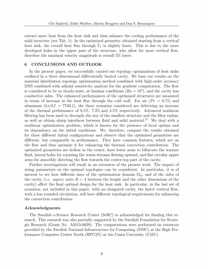
Clio Saglietti, Eddie Wadbro, Martin Berggren and Dan S. Henningson
extract more heat from the heat sink and thus enhance the cooling performance of thesolid structure (see Tab. 1). In the optimized geometry obtained starting from a verticalheat sink, the overall heat flux through Γ1 is slightly lower. This is due to the moredeveloped holes in the upper part of the structure, who allow for more vertical flow,therefore the maximal velocity magnitude is overall 3% lower.
6 CONCLUSIONS AND OUTLOOK
In the present paper, we successfully carried out topology optimization of heat sinksconfined in a three dimensional differentially heated cavity. We base our results on thematerial distribution topology optimization method combined with high-order accuracyDNS combined with adjoint sensitivity analysis for the gradient computation. The flowis considered to be in steady-state, at laminar conditions (Ra = 104), and the cavity hasconductive sides. The enhanced performances of the optimized structures are measuredin terms of increase in the heat flux through the cold wall. For air (Pr = 0.71) andaluminum (ks/kf = 7749.1), the three scenarios considered are delivering an increaseof the thermal performance of 8.5%, 7.3%,and 4.5% respectively. Advanced nonlinearfiltering has been used to decouple the size of the smallest structure and the filter radius,as well as obtain sharp interfaces between fluid and solid material.17 We deal with anonlinear optimization problem, which is known for the presence of local optima andits dependency on the initial conditions. We, therefore, compare the results obtainedfor three different initial configurations and observe that the optimized geometries aredifferent, but comparable in performance. They have common features, which act onthe flow and thus optimize it for enhancing the thermal convection contribution. Theoptimized geometries are hollow in the center, have lower arms to bifurcate the warmerfluid, lateral holes for rejoining the warm streams flowing upward, and flat circular upperarms for smoothly directing the flow towards the center-top part of the cavity.
Further investigations will result in an extension of the present work. The impact ofsizing parameters on the optimal topologies can be considered. In particular, it is ofinterest to see how different sizes of the optimization domain ΩO, and of the sides ofthe cavity (i.e. aspect ratio R = 4 between the height and the other dimensions of thecavity) affect the final optimal design for the heat sink. In particular, in the last set ofscenarios, not included in this paper, with an elongated cavity, the faster vertical flow,with a less rounded circulation, will have different topological requirements for enhancingthe convection contribution.
Acknowledgments
The Swedish e-Science Research Center (SeRC) is acknowledged for funding this re-search. This research was also partially supported by the Swedish Foundation for Strate-gic Research (Grant No. AM13-0029). The computations were performed on resourcesprovided by the Swedish National Infrastructure for Computing (SNIC) at the High Per-formance Computer Center North (HPC2N) at the Umea University (UMU).
9

Clio Saglietti, Eddie Wadbro, Martin Berggren and Dan S. Henningson
θ0.98
0.12
Figure 2: Optimized designs compared with the initial designs, from which they have been obtained.In gray, the structure (contour ρ = 0.5); with the pseudo-colors of the temperature θ, the flow structurerepresented by an iso-contour |u| = 0.19. Left: Initial designs with surrounding flow. Center: Optimizedtopologies with surrounding flow. Right: Zoom on the optimal structures.
10

Clio Saglietti, Eddie Wadbro, Martin Berggren and Dan S. Henningson
REFERENCES
1 M.P. Bendsøe and N. Kikuchi. Generating optimal topologies in structural design usinga homogenization method. Computer Methods in Applied Mechanics and Engineering,71(2):197–224, 1988.
2 M.P. Bendsøe and O. Sigmund. Topology Optimization: Theory, Methods, and Appli-cations. Springer Berlin Heidelberg, thrird edition edition, 2011.
3 T.E. Bruns. Topology optimization of convection-dominated, steady-state heat transferproblems. International Journal of Heat and Mass Transfer, 50:2859–2873, 2007.
4 T. Borrvall and J. Petersson. Topology optimization of fluids in Stokes flow. Interna-tional Journal for Numerical Methods in Fluids, 41(1):77–107, 2003.
5 A.A. Koga, E.C.C. Lopes, H.F.V. Nova, C.R. De Lima, and E.C.N. Silva. Developmentof heat sink device by using topology optimization. International Journal of Heat andMass Transfer, 64:759–772, 2013.
6 J. Alexandersen, N. Aage, C.S. Andreasen, and O. Sigmund. Topology optimisation fornatural convection problems. International Journal for Numerical Methods in Fluids,76(10):699–721, 2014.
7 C. Saglietti, P. Schlatter, E. Wadbro, M. Berggren, and D.S. Henningson. Topologyoptimization of heat sinks in a square differentially heated cavity. Submitted, 2018.
8 J. Alexandersen, O. Sigmund, and N. Aage. Large scale three-dimensional topologyoptimisation of heat sinks cooled by natural convection. International Journal of Heatand Mass Transfer, 100:876–891, 2016.
9 K. Yaji, T. Yamada, S. Kubo, K. Izui, and S. Nishiwaki. A topology optimizationmethod for a coupled thermal–fluid problem using level set boundary expressions. In-ternational Journal of Heat and Mass Transfer, 81:878–888, 2015.
10 C. H Villanueva and K. Maute. CutFEM topology optimization of 3d laminar incom-pressible flow problems. Computer Methods in Applied Mechanics and Engineering,320:444–473, 2017.
11 D. Goldstein, R. Handler, and L. Sirovich. Modeling a no-slip flow boundary with anexternal force field. Journal of Computational Physics, 105(2):354–366, 1993.
12 H.C. Brinkman. A calculation of the viscous force exerted by a flowing fluid on a denseswarm of particles. Flow, Turbulence and Combustion, 1(1):27, 1949.
13 T.E. Bruns. Topology optimization of convection-dominated, steady-state heat transferproblems. International Journal of Heat and Mass Transfer, 50(15):2859–2873, 2007.
11

Clio Saglietti, Eddie Wadbro, Martin Berggren and Dan S. Henningson
14 S. Xin and P. Le Quere. Linear stability analyses of natural convection flows in adifferentially heated square cavity with conducting horizontal walls. Physics of Fluids,13(9):2529–2542, 2001.
15 P.F. Fischer, J.W. Lottes, and S.G. Kerkemeier. Nek5000 web page. Web page:http://nek5000. mcs. anl. gov, 2008.
16 V. Citro, P. Luchini, F. Giannetti, and F. Auteri. Efficient stabilization and accel-eration of numerical simulation of fluid flows by residual recombination. Journal ofComputational Physics, 344:234–246, 2017.
17 L. Hagg and E. Wadbro. Nonlinear filters in topology optimization: existence of solu-tions and efficient implementation for minimum compliance problems. Structural andMultidisciplinary Optimization, 55(3):1017–1028, 2017.
18 J.D. Hellums and S.W. Churchill. Transient and steady state, free and natural con-vection, numerical solutions: Part I. The isothermal, vertical plate. AIChE Journal,8(5):690–692, 1962.
19 M.O. Deville, P.F. Fischer, and E.H. Mund. High-order Methods for IncompressibleFluid Flow, volume 9. Cambridge university press, 2002.
20 Y. Maday and A.T. Patera. Spectral element methods for the incompressible Navier-Stokes equations. In IN: State-of-the-art surveys on computational mechanics (A90-47176 21-64)., pages 71–143, 1989.
21 M.A. Bucci. Subcritical and Supercritical Dynamics of Incompressible Flow over Minia-turized Roughness Elements. Phd thesis, Ecole Nationale Superieure d’Arts et Metiers,Paris, 2017.
22 T. Borrvall. Topology optimization of elastic continua using restriction. Archives ofComputational Methods in Engineering, 8(4):351–385, 2001.
23 O. Sigmund. Morphology-based black and white filters for topology optimization. Struc-tural and Multidisciplinary Optimization, 33(4):401–424, 2007.
24 F. Y. Shih. Image Processing and Mathematical Morphology: Fundamentals and Appli-cations. CRC press, 2009.
25 T.E. Bruns and D.A. Tortorelli. Topology optimization of non-linear elastic structuresand compliant mechanisms. Computer Methods in Applied Mechanics and Engineering,190(26):3443–3459, 2001.
26 K. Svanberg. The method of moving asymptotes a new method for structural opti-mization. International Journal for Numerical Methods in Engineering, 24(2):359–373,1987.
12