Embed Size (px)
Citation preview

Heat Transfer of Oxy-Fuel Flames to Glass:
The Role of Chemistry and Radiation
PROEFSCHRIFT
ter verkrijging van de graad van doctor aan deTechnische Universiteit Eindhoven, op gezag van deRector Magnificus, prof.dr.ir. C.J. van Duijn, voor een
commissie aangewezen door het College voorPromoties in het openbaar te verdedigenop woensdag juni om . uur
door
Marcel Franciscus Gerardus Cremers
geboren te Venray
Dit proefschrift is goedgekeurd door de promotor:
prof.dr. L.P.H. de Goey
Copromotor:dr. K.R.A.M. Schreel
Dit proefschrift is mede tot stand gekomen door financiele bijdrage vanPhilips Lighting B.V.
Copyright c© by M.F.G. CremersAll rights reserved. No part of this publication may be reproduced, stored in a re-trieval system, or transmitted, in any form, or by any means, electronic, mechanical,photocopying, recording, or otherwise, without the prior permission of the author.
Cover design: Paul VerspagetPaul Verspaget
Carin Bruinink Grafische Vormgeving - Communicatie
Cover photo: Heating lamp glass with oxy-fuel burnersCopyright c© by Philips Lighting B.V.
Printed by PrintPartners Ipskamp B.V..
A catalogue record is available from the Library Eindhoven University ofTechnology
ISBN-10: 90-386-2668-1
ISBN-13: 978-90-386-2668-0

To my parents and sister

iv Contents
Contents
1 General introduction 11.1 Background . . . . . . . . . . . . . . . . . . . . . . . . . . . . . . . . . 11.2 Problem Definition . . . . . . . . . . . . . . . . . . . . . . . . . . . . . 21.3 Objectives . . . . . . . . . . . . . . . . . . . . . . . . . . . . . . . . . . 31.4 Deliverables . . . . . . . . . . . . . . . . . . . . . . . . . . . . . . . . . 41.5 Scope of the Thesis . . . . . . . . . . . . . . . . . . . . . . . . . . . . . 4
1.5.1 Heat transfer of a chemically reacting stagnation flow to anobject . . . . . . . . . . . . . . . . . . . . . . . . . . . . . . . . . 5
1.5.2 Heat transfer in a glass object . . . . . . . . . . . . . . . . . . . 61.5.3 From heat transfer predictions towards burner design . . . . . 7
1.6 Outline of the thesis . . . . . . . . . . . . . . . . . . . . . . . . . . . . . 8
2 Chemically reacting stagnation flow 92.1 General introduction . . . . . . . . . . . . . . . . . . . . . . . . . . . . 9
2.1.1 Stagnation flow . . . . . . . . . . . . . . . . . . . . . . . . . . . 92.1.2 Flame chemistry . . . . . . . . . . . . . . . . . . . . . . . . . . 112.1.3 Stagnation layer chemistry . . . . . . . . . . . . . . . . . . . . 122.1.4 Gas radiation . . . . . . . . . . . . . . . . . . . . . . . . . . . . 14
2.2 Governing Equations . . . . . . . . . . . . . . . . . . . . . . . . . . . . 142.2.1 Conservation Equations . . . . . . . . . . . . . . . . . . . . . . 152.2.2 Equations of State . . . . . . . . . . . . . . . . . . . . . . . . . . 162.2.3 Diffusion Models and Transport Coefficients . . . . . . . . . . 172.2.4 Gas Chemistry . . . . . . . . . . . . . . . . . . . . . . . . . . . 18
2.3 Boundary conditions . . . . . . . . . . . . . . . . . . . . . . . . . . . . 202.3.1 Inlet Boundary Conditions . . . . . . . . . . . . . . . . . . . . 202.3.2 Stagnation Plane Boundary Conditions . . . . . . . . . . . . . 20
2.4 This thesis . . . . . . . . . . . . . . . . . . . . . . . . . . . . . . . . . . 232.4.1 Assumptions . . . . . . . . . . . . . . . . . . . . . . . . . . . . 232.4.2 Equations . . . . . . . . . . . . . . . . . . . . . . . . . . . . . . 262.4.3 Computational strategy . . . . . . . . . . . . . . . . . . . . . . 28

vi Contents
3 Heating of glass objects 293.1 General introduction . . . . . . . . . . . . . . . . . . . . . . . . . . . . 29
3.1.1 Chemical and thermodynamic properties . . . . . . . . . . . . 293.1.2 Optical properties . . . . . . . . . . . . . . . . . . . . . . . . . 30
3.2 Governing Equations . . . . . . . . . . . . . . . . . . . . . . . . . . . . 313.2.1 Energy Conservation Equation . . . . . . . . . . . . . . . . . . 323.2.2 Radiation . . . . . . . . . . . . . . . . . . . . . . . . . . . . . . 32
3.3 Boundary Conditions . . . . . . . . . . . . . . . . . . . . . . . . . . . . 353.4 This thesis . . . . . . . . . . . . . . . . . . . . . . . . . . . . . . . . . . 36
3.4.1 Assumptions . . . . . . . . . . . . . . . . . . . . . . . . . . . . 363.4.2 Equations . . . . . . . . . . . . . . . . . . . . . . . . . . . . . . 373.4.3 Computational strategy . . . . . . . . . . . . . . . . . . . . . . 38
4 Heat transfer mechanisms of laminar flames of hydrogen+oxygen 394.1 Introduction . . . . . . . . . . . . . . . . . . . . . . . . . . . . . . . . . 404.2 Governing equations . . . . . . . . . . . . . . . . . . . . . . . . . . . . 424.3 Time scale analysis of the stagnation flame . . . . . . . . . . . . . . . 454.4 Time scale analysis for the quartz glass product . . . . . . . . . . . . . 474.5 Heat transfer of a non-reactive stagnation flow . . . . . . . . . . . . . 504.6 Heat transfer of a reactive stagnation flow . . . . . . . . . . . . . . . . 524.7 Chemical equilibrium . . . . . . . . . . . . . . . . . . . . . . . . . . . . 544.8 Surface chemistry . . . . . . . . . . . . . . . . . . . . . . . . . . . . . . 554.9 Conclusions . . . . . . . . . . . . . . . . . . . . . . . . . . . . . . . . . 58
5 Thermochemical heat release of laminar stagnation flames of fuel+oxygen 595.1 Introduction . . . . . . . . . . . . . . . . . . . . . . . . . . . . . . . . . 605.2 Conservation equations and boundary conditions . . . . . . . . . . . 625.3 Spatial analysis of the stagnation flame . . . . . . . . . . . . . . . . . 64
5.3.1 Flame front . . . . . . . . . . . . . . . . . . . . . . . . . . . . . 655.3.2 Thermal boundary layer . . . . . . . . . . . . . . . . . . . . . . 675.3.3 Equilibrium zone . . . . . . . . . . . . . . . . . . . . . . . . . . 67
5.4 Chemistry in the stagnation boundary layer . . . . . . . . . . . . . . . 695.5 Conclusions . . . . . . . . . . . . . . . . . . . . . . . . . . . . . . . . . 72
6 Integrated radiative transfer equation for gray and non-gray media 736.1 Introduction . . . . . . . . . . . . . . . . . . . . . . . . . . . . . . . . . 746.2 Theory . . . . . . . . . . . . . . . . . . . . . . . . . . . . . . . . . . . . 77
6.2.1 Conservation equations . . . . . . . . . . . . . . . . . . . . . . 776.2.2 Boundary conditions . . . . . . . . . . . . . . . . . . . . . . . . 786.2.3 Discretization . . . . . . . . . . . . . . . . . . . . . . . . . . . . 796.2.4 Solution of the integrated RTE for a spectral band . . . . . . . 80
6.3 Discussion . . . . . . . . . . . . . . . . . . . . . . . . . . . . . . . . . . 836.3.1 A model problem: heat flux inaccuracies . . . . . . . . . . . . 84

Contents vii
6.3.2 The radiative source term . . . . . . . . . . . . . . . . . . . . . 866.3.3 Practical situations . . . . . . . . . . . . . . . . . . . . . . . . . 89
6.4 Conclusion . . . . . . . . . . . . . . . . . . . . . . . . . . . . . . . . . . 94
7 From heat transfer predictions towards burner design 977.1 Introduction . . . . . . . . . . . . . . . . . . . . . . . . . . . . . . . . . 977.2 Fuel gas . . . . . . . . . . . . . . . . . . . . . . . . . . . . . . . . . . . . 997.3 Thermochemical heat release . . . . . . . . . . . . . . . . . . . . . . . 1037.4 Radiative heat loss of a glass plate . . . . . . . . . . . . . . . . . . . . 107
8 General conclusions 1118.1 Chemically reacting stagnation flow . . . . . . . . . . . . . . . . . . . 1118.2 Heat transfer in a glass object . . . . . . . . . . . . . . . . . . . . . . . 1128.3 From heat transfer predictions to burner design . . . . . . . . . . . . 113
A Gamma-functions 115
B Tables 117B.1 Blackbody fractions . . . . . . . . . . . . . . . . . . . . . . . . . . . . . 117
Bibliography 119
Summary 129
Samenvatting 131
Curriculum Vitae 133
Dankwoord 135

viii Contents

Chapter1General introduction
1.1 Background
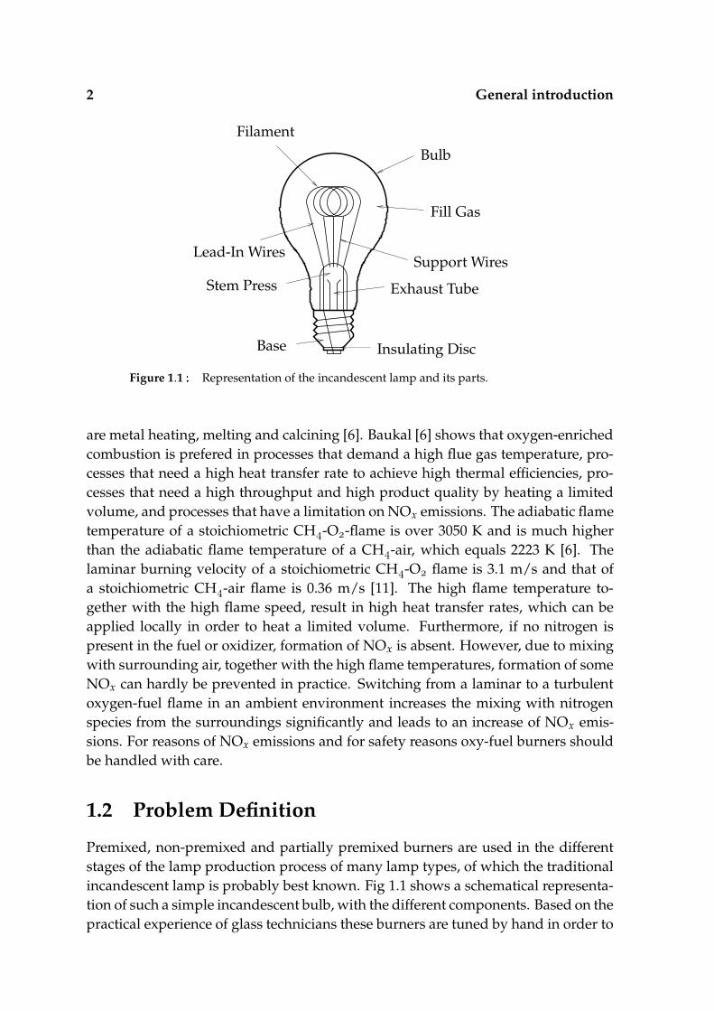
The first practical electrical lamp was the incandescent lamp produced by ThomasEdison in 1879. Edison used a glass light bulb with a thin carbonized cotton sewingthread as filament material. This was the starting point for the development of elec-trical lamps for many purposes. Today, lamps are used in many devices and envi-ronments, which has led to thousands of different lamp types. Typical applicationsare household appliances, automotive applications, office and industrial lighting,theatre and arena lighting, road and airport lighting, etc. Most of the lamp typescan be placed within one of the categories [99]: incandescent, tungsten halogen,fluorescent, mercury, metal halide, and sodium lamps, and are available in a vari-ety of shapes and sizes. These lamps are filled with a gas at low, ambient or highpressure. Fig. 1.1 shows a schematic representation of an incandescent lamp. Themain production steps for most lamp types are shaping the outer bulb, globe ortube, if needed implementing the high pressure glass core element, fixing the elec-trical components, evacuating the air and adding the fill gas, and fixing the neckand base elements. These steps can be divided in many substeps, which have to beperformed in order to produce a lamp. In many of these steps, the glass is meltedlocally by means of flame impingement, and a variety of glass types is used. Themost important requirement of the glass used in electric bulbs is to form a trans-parent envelope around the light source, i.e. the emission of light of the filament orcharged gas [104], or alternatively allow deposition of a coating which transformsthe light emitted by the gas into visible light. Depending on the required opticalproperties of the glass, and on the pressure and temperature inside the lamp, theglass can be a soft glass, hard glass or even quartz glass, which has a high meltingtemperature of around 2000 K. In order to reach the high melting temperatures, of-ten flames are used based on mixtures of a fuel and pure oxygen, commonly referedto as oxy-fuel mixtures. These flames possess a high flame temperature, togetherwith a high flame speed. As a result, the energy throughput is high, and so is theheat transfer rate of these impinging oxy-fuel flames to the products.
Oxy-fuel burners are not only used for heating parts in the production processof a lamp, but also for many other purposes. Many industrial heating processes usepure oxygen or oxygen-enriched air as oxidizer for combustion. Typical applications
2 General introduction
Bulb
Fill Gas
Exhaust Tube
Insulating DiscBase
Filament
Support Wires
Stem Press
Lead-In Wires
Figure 1.1 Representation of the incandescent lamp and its parts.
are metal heating, melting and calcining [6]. Baukal [6] shows that oxygen-enrichedcombustion is prefered in processes that demand a high flue gas temperature, pro-cesses that need a high heat transfer rate to achieve high thermal efficiencies, pro-cesses that need a high throughput and high product quality by heating a limitedvolume, and processes that have a limitation on NOx emissions. The adiabatic flametemperature of a stoichiometric CH-O-flame is over 3050 K and is much higherthan the adiabatic flame temperature of a CH-air, which equals 2223 K [6]. Thelaminar burning velocity of a stoichiometric CH-O flame is 3.1 m/s and that ofa stoichiometric CH-air flame is 0.36 m/s [11]. The high flame temperature to-gether with the high flame speed, result in high heat transfer rates, which can beapplied locally in order to heat a limited volume. Furthermore, if no nitrogen ispresent in the fuel or oxidizer, formation of NOx is absent. However, due to mixingwith surrounding air, together with the high flame temperatures, formation of someNOx can hardly be prevented in practice. Switching from a laminar to a turbulentoxygen-fuel flame in an ambient environment increases the mixing with nitrogenspecies from the surroundings significantly and leads to an increase of NOx emis-sions. For reasons of NOx emissions and for safety reasons oxy-fuel burners shouldbe handled with care.
1.2 Problem Definition
Premixed, non-premixed and partially premixed burners are used in the differentstages of the lamp production process of many lamp types, of which the traditionalincandescent lamp is probably best known. Fig 1.1 shows a schematical representa-tion of such a simple incandescent bulb, with the different components. Based on thepractical experience of glass technicians these burners are tuned by hand in order to

1.3 Objectives 3
Dn
δf
H
FlameFront
TubeShell
x, u
y, v
BurntGas
UnburntGas
NozzleExit
D
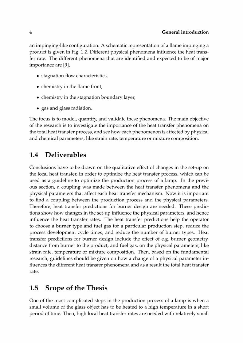
Figure 1.2 Schematical burner set-up with a premixed flame impinging a tube.
optimize the efficiency of the production process. There are several problems asso-ciated with this practice. The main problem is that the development of a productionprocess of a new lamp type is an extensive and time-consuming task. The burnertype, type of fuel gas, and burner set-up is often chosen on a subjective basis. As aresult, the cycle times when developing a new lamp making process are relativelylong. Then, the change-over times are relatively long when a production line hasto be adapted for the production of another lamp type. For both new and adaptedproduction processes, it is not known if the chosen set-up is the optimal set-up, andfurther optimization is often desired. Optimization is mostly explained in terms ofprocess speedup, increasing process stability, and increasing production flexibility.Furthermore, the controllability and efficiency of the lamp production process needsto be improved. In many cases, the production process can be optimized, but theoptimization is an elaborate task and is difficult to verify. To optimize this processat Philips Lighting B.V. a research project has been started. This project is a jointresearch effort of Philips Lighting B.V. and Eindhoven University of Technology, tostudy the heat transfer of impinging oxy-fuel flames to (quartz) glass products, byperforming an in-depth study on the heat transfer phenomena involved in the heat-ing of an object.
1.3 Objectives
Optimization of the production process can only be achieved if there is a clearknowledge of the process of heating a (quartz)-glass product with oxy-fuel flames in
4 General introduction
an impinging-like configuration. A schematic representation of a flame impinging aproduct is given in Fig. 1.2. Different physical phenomena influence the heat trans-fer rate. The different phenomena that are identified and expected to be of majorimportance are [9],
• stagnation flow characteristics,
• chemistry in the flame front,
• chemistry in the stagnation boundary layer,
• gas and glass radiation.
The focus is to model, quantify, and validate these phenomena. The main objectiveof the research is to investigate the importance of the heat transfer phenomena onthe total heat transfer process, and see how each phenomenon is affected by physicaland chemical parameters, like strain rate, temperature or mixture composition.
1.4 Deliverables
Conclusions have to be drawn on the qualitative effect of changes in the set-up onthe local heat transfer, in order to optimize the heat transfer process, which can beused as a guideline to optimize the production process of a lamp. In the previ-ous section, a coupling was made between the heat transfer phenomena and thephysical parameters that affect each heat transfer mechanism. Now it is importantto find a coupling between the production process and the physical parameters.Therefore, heat transfer predictions for burner design are needed. These predic-tions show how changes in the set-up influence the physical parameters, and henceinfluence the heat transfer rates. The heat transfer predictions help the operatorto choose a burner type and fuel gas for a particular production step, reduce theprocess development cycle times, and reduce the number of burner types. Heattransfer predictions for burner design include the effect of e.g. burner geometry,distance from burner to the product, and fuel gas, on the physical parameters, likestrain rate, temperature or mixture composition. Then, based on the fundamentalresearch, guidelines should be given on how a change of a physical parameter in-fluences the different heat transfer phenomena and as a result the total heat transferrate.
1.5 Scope of the Thesis
One of the most complicated steps in the production process of a lamp is when asmall volume of the glass object has to be heated to a high temperature in a shortperiod of time. Then, high local heat transfer rates are needed with relatively small

1.5 Scope of the Thesis 5
flames that possess a high flame temperature and high flame velocity. Therefore,flames based on mixtures of a fuel and pure oxygen are used. The diameter of thenozzle exit is relatively small, and as a result, the flames are laminar. To increasethe heat transfer rate even more, the flame tip is placed close to the object surface.Quartz glass is chosen as solid material, because this glass type has a much highermelting temperature than many other glass types, and therefore requires the highestheat transfer rates. In section 2.4.1 it is shown that a one-dimensional approximationof the flow, chemistry and thermodynamics is expected to be a fair representation ofthe real three-dimensional problem. Therefore, a one-dimensional numerical studyis conducted to determine the heat transfer from premixed laminar oxy-fuel stagna-tion flames to quartz glass products. Furthermore, the products considered, oftenhave a tubular shape with a radius much larger than the shell thickness. As a result,a one-dimensional infinite plate is the considered geometry for the glass object.
The research is mainly conducted within two PhD-projects. M.J. Remie mainlyfocusses on the influence of flow phenomena on the heat transfer rates, which willbe presented in a seperate thesis. The results presented in this thesis discuss (1)the effect of flame chemistry and chemistry in the stagnation boundary layer on theheat transfer rate of a chemically reacting stagnation flow to an object, (2) the effectof radiative heat transfer on the heating process of a glass object. The chemicallyreactive stagnation flow and the object are treated seperately throughout the thesis.This is allowed because the heating time scale of the glass plate is much larger thanthe heating, transport and chemical time scales of the chemically reacting flow. Thetypical heating time scales of the stagnation flow and object are determined andoutlined in chapter 4.
1.5.1 Heat transfer of a chemically reacting stagnation flow to anobject
Extensive research has been undertaken by various researchers on the heat trans-fer of stagnation flames to products. Most studies, however, are semi-analyticalderivations of stagnation point heat transfer rates, of inert and reactive hot gases toobjects. In most of these studies, flame calculations are not performed, and the effectof chemistry in the boundary layer on the heat transfer rate is taken into account bymeans of enthalpy differences. On the other hand, the stagnation flame calculationswith complex chemistry calculations are usually based on mixtures of a fuel and air.Results of stagnation flames based on oxy-fuel mixtures with complex chemistrycalculations are very scarce. Therefore, an extensive study, with full chemical calcu-lations, is undertaken in order to determine the heat transfer of oxy-fuel stagnationflames to objects.
A non-reacting hot gas impinging an inert surface is taken as the basic problem,and is currently under investigation. For this problem, analytical solutions can bederived, and the heat transfer rates can be estimated, see e.g. [110]. When flame
6 General introduction
chemistry and stagnation layer chemistry is taken into account, the heating processof the product is affected significantly, and the question arises how these phenomenainfluence the heat transfer process.
First, flame chemistry is studied by comparing a hydrogen-oxygen and a hydrogen-air mixture. Since heat transfer is largely determined by typical flame speeds andadiabatic flame temperatures, flame speeds and temperatures for both mixtures aredetermined with different complex reaction mechanisms in chapter 4. Flame speedsand temperatures for oxy-fuel mixtures with acetylene, propane and butane as fuelgas are given in chapters 5 and 7.
Second, dissociated species in the burned gases enter the cool stagnation layerand may recombine exothermally into stable products, releasing heat and boostingthe heat transfer. This process is also called thermochemical heat release (TCHR).When the flame is far from the object, the flue gases will reach chemical equilibriumbefore they enter the stagnation boundary layer. Then, the equilibrium composi-tion of the burned gases consists mainly of decomposed species, even if the initialoxy-fuel composition consisted of higher alkanes, and a relatively simple reactionmechanism can be used to calculate the recombination chemistry near and at thesurface. In chapter 5 it is shown under which conditions chemical equilibrium isreached. The effect of recombination in the stagnation boundary layer is studied fora H-O-mixture in chapter 4 and for different CxHy-mixtures in chapter 5. If thestagnation layer is not in chemical equilibrium, surface reactions may enhance theheat transfer rate even further. The effect of recombination reactions on the totalheat transfer rate directly at a surface, by imposing a chemically active Platinumsurface, is discussed in chapters 4.
Third, the effect of the local strain rate on the total heat transfer rate is investi-gated. The local strain rate is a typical parameter of the flow, and is directly coupledto the local velocity gradient. An analytical approximation for the heat transfer co-efficient is derived for a non-reacting stagnation flow with negligible viscosity in thesublayer. The effect of the strain rate on the heat transfer coefficient is incorporatedin the approximation. The heat transfer coefficients calculated with this approxima-tion are compared with heat transfer coefficients determined numerically for stag-nation flows with and without recombination in the stagnation boundary layer, seechapter 4. The effect of the strain rate on the ability of the flue gas to reach chemicalequilibrium before entering the stagnation boundary layer is investigated in chap-ter 5, while the effect of the strain rate on the addition of TCHR to the total heattransfer rate is outlined in chapter 4.
1.5.2 Heat transfer in a glass object
The glass object is heated by a stagnation flame. At low temperatures, the mainheat transfer mechanism inside the glass is conduction. Once the object reachesa higher temperature, radiative heat transfer becomes an important heat transfer
1.5 Scope of the Thesis 7
mechanism. Heat transfer by radiation redistributes heat inside the object, and isthe dominant heat loss mechanism from the object to the surroundings. The heatlosses have to be determined in an adequate way to simulate the heating processaccurately. The temperature gradients inside the product have to be determined ac-curately to know the thermal stresses. Determining the heat transfer in a glass objectis a combined conduction-radiation problem. A glass is a semi-transparent medium,and spectral solution techniques have to be applied to determine the radiative heattransfer rates accurately. With the traditional solution techniques, if the medium issemi-transparent and internal temperature gradients are high, significant inaccura-cies have to be allowed when the heat fluxes are calculated on the same course gridas the conductive fluxes. Chapter 6 shows a new spectral band formulation withwhich the radiative heat fluxes can be determined accurately on a course grid withlarge temperature gradients.
The new method is applied to a combined conduction-radiation problem. Firstit is assumed that the medium has optical properties that are independent of wave-length, i.e. a gray medium. The effect of the gray absorption coefficient on thetypical heat loss, temperature gradient and cooling time scale is investigated. Thena medium with semi-transparent optical properties is considered, consisting of onealmost completely transparent spectral band for short wavelengths, and one almostcompletely absorbing spectral band for long wavelengths and which is a typical op-tical property for glass. The transition from the transparent to the absorbing bandoccurs at a cutoff wavelength. The position of the cutoff wavelength can be verydifferent for different glass types. Therefore, the effect of the position of the cutoffwavelength on the typical heat loss, temperature gradient and cooling time scale isalso investigated.
1.5.3 From heat transfer predictions towards burner design
The different heat transfer phenomena will be studied from a fundamental pointof view throughout the main part of the thesis. Based on this fundamental knowl-edge, some predictions will be presented in chapter 7. These predictions show howchanges in the set-up influence the physical parameters that determine the heattransfer rate. It should be noted that the influence of flow phenomena will mainlybe treated by M.J Remie in a seperate thesis. In this thesis we will focus on
• how the chosen fuel gas determines the flow velocity of the burned mixture,the sensible and chemical enthalpy of the burned mixture, and the maximumstrain rate
• how the chosen fuel gas, and C/H-ratio, determines the heat flux ratio includ-ing TCHR and without TCHR
• how the maximum temperature of a glass plate can be estimated if the opticalproperties of the glass are known.

8 General introduction
1.6 Outline of the thesis
The chemically reacting stagnation flow, and the heating of the glass object aretreated more or less seperately throughout this thesis. Chapter 2 discusses the the-ory of a stagnation flow, including a summary of the different physical and chemicalphenomena that are present in a reacting stagnation flow, the governing equationsand boundary conditions in vector notation, and the equations in one-dimensionalform as used in the remainder of this thesis. Chapter 3 discusses the theory of solidobject heating, including the thermodynamic and optical properties of the solid,the governing equations and boundary conditions for the solid, and a detailed dis-cription of radiative heat transfer inside a semi-transparent medium. Chapters 4, 5and 6 discuss the main findings and results extensively. Chapter 4 and 5 treat thephenomena in the chemically reactive stagnation flow, and Chapter 6 treats radia-tive transport in a solid material. These chapters are reprints of submitted, acceptedor published articles. Chapter 7 shows how some of the heat transfer predictionscan be applied for burner design. The thesis ends up with general conclusions anda summary.

Chapter2Chemically reactingstagnation flow
This chapter discusses the theory of a chemically reacting stagnation flow impingingagainst an object. In section 2.1 a general introduction is presented of different phys-ical and chemical phenomena in a chemically reacting stagnation flow. In section 2.2chemically reacting stagnation flow equations are presented in vector notation, andsection 2.3 presents the corresponding boundary conditions. Finally, in section 2.4 itis shown that the flow can be approximated by a one-dimensional problem, and theone-dimensional equations that are used in the remainder of this thesis are given.
2.1 General introduction
In this section a discription is given of a stagnation flow, flame chemistry, stagna-tion boundary layer chemistry and gas radiation, and how these phenomena mayinfluence the heat transfer.
2.1.1 Stagnation flow
Both laminar and turbulent flames are often used in industrial heating processes.Turbulent flames are mostly used when the combustion mode is of the non-premixedtype and intense mixing is needed to enhance combustion, for example in industrialovens, aviation jet turbines and compression ignition engines. On the other hand,in the lamp making process, premixed high velocity burners are often used, and aschematic representation is given in Fig. 1.2 The nozzle diameter Dn is small, withthe Reynolds number based on the nozzle diameter and the mean velocity, viscosity,and density of the gas in the nozzle of the order of 10-10, while the Reynolds num-ber in the flame front based on the typical stream tube width, the laminar burningvelocity, viscosity and density in the flame front is of the order of 10. As a resultthe flame jets studied in this thesis are considered laminar. Depending on the nozzlegeometry the unburned mixture leaves the nozzle exit as a plug flow or (partially)developed flow. After combustion takes place a flame jet impinges the object.
When using an impinging flame jet with flame temperatures up to approxi-mately 1700 K forced convection is the dominant heat transfer mechanism [5, 65].

10 Chemically reacting stagnation flow
It was understood that for these low temperature flames, the share of forced con-vection in the total heat transfer may be 70-90% [8, 95]. This type of flow is oftencalled frozen flow, since no chemical reactions are involved. In that case no heatrelease occurs from chemical reactions near the target surface [72]. As a result, forthese low temperature flames forced convection is often considered as the only heattransfer mechanism. Semi-analytical solutions for the heat transfer from stagnationflows to objects of different shapes have been studied extensively. In most of thesesolutions the heat transfer in the stagnation point is considered. In the original so-lutions, where a uniform flow impinges normally to a body of revolution, the radialflow component at the stagnation edge of the stagnation boundary layer is deter-mined from potential flow theory and is given by,
v βy (2.1)
with y the distance along the body. The constant β is known as the stagnation ve-locity gradient, and we will later redefine it as the local strain rate K. At the edge ofthe stagnation zone, β is constant and equal to,
βs (
∂v∂y
)
y ,x δe
(2.2)
with v the velocity in radial direction y, x δe the outer edge of the stagnationboundary layer, and y a position on the centerline axis. For a one-dimensionalstagnation flow, Eq. (2.2) holds for ≤ y ≤ . The factor βs is also known asthe surface velocity gradient [5], or the velocity gradient in the radial direction,outside of the boundary layer, in the vicinity of the stagnation point [94, 55, 105].For a sphere, disk, and cylinder in crossflow, analytical solutions for βs have beenfound [66, 93]. For an axisymmetric planar jet impinging normally onto a flat plateof infinite size, the factor βs has been derived as [118],
βs πue
dj(2.3)
with ue the velocity normal to the stagnation plane and dj the jet width at the edgeof the stagnation boundary layer. In the derivation it was assumed that the veloc-ity far away from the stagnation plane is uniform and approximately equal to ue.From experimental studies using semi-analytical solutions, van der Meer [93] ob-tained a βs-value equal to βs uN/DN at small burner to plate distances, with uN
the uniform velocity in the nozzle exit and DN the nozzle exit diameter. Kilham etal. [73] found for various laminar oxy-fuel flame jets impinging onto a flat plate thatβs ue/dj. Sibulkin [121] derived an expression for the heat flux at the stagnationpoint, with an external uniform flow impinging against a body of revolution,
q ′′s .
βsρeµe . Pr .
e cpeTe Ts (2.4)
2.1 General introduction 11
where ρe, µe, Pre and cpe are the density, viscosity, Prandtl number, and specific heatcapacity at the outer edge of the stagnation boundary layer respectively. Since Te isthe temperature of the external flow at the outer edge of the stagnation boundarylayer, and Ts is the wall, or stagnation plane, temperature, the heat flux is driven bythis temperature difference. Many semi-analytical solutions, see e.g. [94, 44, 113, 56,50, 52, 24], for laminar and turbulent stagnation flows, with and without chemicalreactions, are based on Eq. (2.4).
In contrast to the potential flow-based and semi-analytical solutions, Remie [110]derived an analytical solution for the velocity profile of a non-reacting hot stag-nation flow, impinging against a flat surface. From this profile an expression wasfound for the heat transfer rate in the stagnation point. This expression is written interms of integral functions of dimensionless numbers. If viscosity in the stagnationboundary layer is neglected and the specific heat capacity, thermal conductivity anddensity are taken independent of temperature a simplified expression is found, seechapter 4. With this equation the influence of e.g. the local strain rate, which is de-pendent on the distance to the surface, on the heat transfer rate is studied, and isoutlined in chapter 4.
2.1.2 Flame chemistry
In general, combustion is the exothermic conversion of a fuel and oxidizer into prod-ucts. A fuel can be a solid, a liquid or a gas. In this thesis we will focus on gaseousfuels only, because in the lamp making process only gaseous fuels are adopted.Gaseous fuels are commonly used in industrial applications, and are mostly hydro-carbons like methane or LPG. Sometimes hydrogen is added to the fuel gas and ifhigh flame velocities are needed, hydrogen is used in its pure form. The most com-mon oxidizer is air, which consists mainly of nitrogen and oxygen. However, whenhigh temperatures and flame speeds are needed, often is chosen for pure oxygen asoxidizer.
If the fuel and oxidizer are mixed such that a lean or stoichiometric mixture isobtained, a premixed flame converts the fuel gas to products where the chemicalreactions take place within a thin flame front. Different inlet mixtures lead to differ-ent flame chemistry, and as a result to different laminar flame speeds and adiabaticflame temperatures. The laminar flame speed is determined by the typical diffusionvelocity of the species in the mixture and the typical reaction times.
If the fuel and oxidizer are separate streams a flame front is formed at the po-sition where the fuel and oxidizer stream meet, leading to a non-premixed flame.The mixing is forced by diffusion. If diffusion fluxes of the fuel and oxidizer tothe flame front are high, mixing is enhanced and chemical reactions develop eas-ier, leading to a thinner flame front. In practice, the combustion system is often acombination of a premixed and non-premixed system. A configuration of multipleflame front types, premixed and non-premixed, in the same system is very com-

12 Chemically reacting stagnation flow
mon. Bongers [10] gives a more extensive overview of the general principles incombustion sytems. Configurations in which multiple flames occur are for examplepremixed counterflow flames and triple flames, see e.g. Van Oijen [101]. Althoughin a lamp making manufacturing, a variety of flame types including premixed, non-premixed and partially-premixed flames can be found, we will focus in this thesisonly on premixed flames. Due to its high flame temperature, high flame speed, andrelatively small size, this flame type is commonly used when a high local heat inputis needed.
The higher the flame speed, the higher the mass flux and the higher the heattransfer rate. The reacting gas possesses a chemical and sensible energy content.The sensible energy content of the inlet mixture is determined by the temperature,while the chemical energy content is determined by the initial composition. Oncethe inlet mixture is combusted, it reaches chemical equilibrium with correspondinghigh adiabatic flame temperature. Part of the chemical energy content has beenconverted to sensible energy by chemical reactions. The more chemical energy isconverted to sensible energy, the higher the adiabatic flame temperature and thehigher the heat transfer rate. In chapter 4 laminar flame speeds and adiabatic flametemperatures are determined for hydrogen-oxygen and hydrogen-air mixtures. Inchapter 5 laminar flame speeds and adiabatic flame temperatures are presented fora number of hydrocarbon-oxygen mixtures.
2.1.3 Stagnation layer chemistry
The stagnation point heat transfer rate of a non-reacting flow impinging against asurface is determined by the temperature difference, or difference in sensible en-thalpy, between the hot gas and the cool object surface. However, the hot gas mayconsist of dissociated species, and recombination reactions may take place inside thecool stagnation boundary layer or at the surface. The exothermic recombination ofdissociated gaseous species into stable products is then thermodynamically prefer-able, and leads to an increase of the overall heat transfer rate. This mechanism hasoften been referred to as (chemical) recombination, see e.g. [23, 56, 72, 129, 44, 47,73, 24, 71]. It has also been called convection vivre [64, 8, 95] or aerothermochem-istry [113]. In this thesis, the process will be called thermochemical heat release,after Baukal et al. [5, 3, 4]. The effect of thermochemical heat release in the total heattransfer rate becomes more important when the main stream gas contains a highconcentration of dissociated species. A high concentration of dissociated speciesis reached at high flame temperatures. Oxy-fuel mixtures possess a relatively highflame temperature compared with mixtures based on air, and have therefore a muchhigher content of disscociated species. The reason for this is that mixtures of a fueland air consist of a relatively large amount of inert nitrogen. The N-species in airacts as a heat sink, which moderates the flame temperature and as a result drops theconcentration of dissociated species and the effect of TCHR on the total heat trans-
2.1 General introduction 13
fer rate. At high gas temperatures, TCHR may be of the same order of magnitudeas forced convection [4]. Two TCHR mechanisms are identified by Giedt et al. [47],known as equilibrium TCHR and catalytic TCHR.
In equilibrium TCHR gas-phase chemical reactions occur in the stagnation bound-ary layer. Dissociated species enter the stagnation boundary layer by diffusion andconvection, and have sufficient time to collide with other unstable atoms to formstable products. As long as the typical chemical reaction time is short compared tothe typical diffusion time, the species recombine exothermally in the gaseous phase,enhancing the total heat transfer rate.
In catalytic TCHR, diffusion of dissociated species to the stagnation plane is rel-atively fast compared to the chemical reaction times. Therefore, the dissociatedspecies are not able to form stable products before they reach the stagnation plane,and the reactions may take place at the surface. Recombination may be acceler-ated when the surface is catalytically active. This recombination effect is therefore aheterogeneous effect. Baukal et al. [4] investigated experimentally the heat transferfrom oxygen-enriched natural gas flames impinging normally onto a water-cooleddisk. They compared the stagnation point heat transfer rate to a nearly noncatalyticalumina-coated, untreated and highly catalytic platinum coated disk, and found amaximum difference between the platinum-coated and alumina-coated of approxi-mately 12%.
Nawaz [100] showed that there is also a combined form of equilibrium TCHRand catalytic TCHR possible, and is called mixed TCHR. Some of the disscociatedspecies react in the gaseous phase, while others reach the surface and react catalyti-cally.
In most studies the driving force for convective heat transfer is the differencein sensible enthalpy hS between the main flow and the gas at the stagnation plane.However, with TCHR included, the driving force is the total enthalpy differencehT of the gas flow at the edge of the stagnation boundary layer and the gas rightat the stagnation plane. The total enthalpy consists of the sensible enthalpy andthe chemical enthalpy hC, which is the chemical potential energy of the dissociatedspecies. Analogeous to the sensible heat transfer equation by Sibulkin, Eq. (2.4),semi-analytical solutions have been found for stagnation point heat fluxes includ-ing equilibrium TCHR, for both laminar and turbulent stagnation flows, see e.g. [44,113, 24, 71, 23], where the total enthalpy difference was taken as potential for heattransfer. Semi-analytical solutions of the stagnation point heat transfer rate includ-ing catalytic TCHR have been proposed by e.g. [44, 113, 71]. Furthermore, moststudies are based on mixtures of a fuel and air, while TCHR is especially relevantfor oxy-fuel mixtures. Also the interaction with the flame front is not taken intoaccount. TCHR in the stagnation boundary layer and at the surface for a numberof oxy-fuel mixtures is calculated with complex chemistry models, and results areshown in chapters 4 and 5. Furthermore, interaction with the flame front is investi-gated, and results are discussed in chapter 5.
14 Chemically reacting stagnation flow
2.1.4 Gas radiation
Radiation is produced by the hot flue gas and is often split in nonluminous andluminous radiation. Nonluminous radiation is produced by gaseous species thatcan be found in the burned gases. Among the best emitters are CO and HO,and are present in most oxy-fuel flames. The amount of radiation produced by thegas depends on the gas temperature and partial pressures of the emitting species.Some studies indicate the importance of nonluminous radiation, e.g. [70, 64], whilein other studies nonluminous radiation was found to be very low or negligible,e.g. [47, 33]. Van der Meer [93] states that flame radiation for impinging premixedmethane-air flame jets is negligible because the hot gas layer has a small thicknessand very low emissivity. Purvis [106] showed that for a CH-O and CH-O flameimpinging normal to a surface, the addition of nonluminous radiation to the heattransfer rate from the flame to the target is negligible. Baukal [6] states that in theflame region of an oxy-fuel flame dissociated species, as OH, H and O, are present,which radiatively participate. Baukal mentions that the average absorption coeffi-cient of the furnace gas for a methane-oxygen furnace is increased up to 0.2-0.3 m .However, because the typical flame thickness is of the order of 10 -10 m, the op-tical thickness is typically of the order 10 . At a temperature of T 3054 K themaximum radiative heat flux is then of the order of 10 Wm , which is orders ofmagnitude lower than the convective heat flux. Therefore, radiative heat transfer bynonluminous radiation is not investigated in this study.
Luminous radiation is produced by the soot. Soot particles radiate approxi-mately as a blackbody, and may be an important heat transfer mechanism whenliquid and solid fuels are used. For gaseous fuels luminous radiation is in generalnot important, except when the flames are very fuel rich. Then soot particles maybe formed, leading to luminous radiation. Furthermore, diffusion flames have atendency to form soot and produce luminous radiation. Soot is not present in hightemperature premixed flames. In this study we will focus on high temperature pre-mixed stoichiometric gaseous oxy-fuel flames, from which it can be concluded thatno soot is formed, and no luminous radiation is produced.
2.2 Governing Equations
In this section the transport equations are given for a chemically reacting stagnationflame. In section 2.2.1 the conservation equations for mass, momentum, energyand chemistry are given. In section 2.2.2 the equations of state, i.e. the gas lawand caloric equation are presented, as well as the equations for the thermodynamicvariables. Section 2.2.3 gives an overview of the chemical diffusion models. Finally,a brief outline of the gas chemistry modelling is presented in section 2.2.4.
2.2 Governing Equations 15
2.2.1 Conservation Equations
The conservation equations for chemically reacting flows can be found in manybooks and theses, see e.g. [10, 101, 49, 77, 135, 136]. This section expresses the con-servation equations for mass, momentum, species mass fractions, and enthalpy. Allequations are presented in vector notation so that they are applicable to chemicallyreacting flows in any coordinate system.
Conservation of mass is given by the continuity equation,
∂ρ
∂t
∇ · ρu , (2.5)
with ρ the density, t time and u the velocity vector of the gas mixture. The equationfor conservation of momentum in a multi-component gaseous or fluid flow is,
∂ρu ∂t
∇ · ρuu ∇ ·Π
Ngs
i
ρYibi, (2.6)
where Π is the stress tensor, Yi the mass fraction of species i and bi the externalforce per unit mass acting on species i. Ng
s is the number of species in the gas,and for every species the species mass fraction is defined as Yi ρi/ρ, where ρi isthe mass density of species i. The stress tensor Π consists of a hydrostatic and aviscous part corresponding to Π pI
τ , with p the hydrostatic pressure, I theunit tensor and τ the viscous stress tensor. The stress tensor is determined from thekinetic theory [54], and is given by,
τ (
κ
η
) ∇ · u I η
(
∇u (∇uT
))
, (2.7)
where η is the mean dynamic viscosity of the mixture. The volume viscosity κ de-scribes viscous dissipation due to normal shear stress and is usually neglected inflame simulations [135]. Conservation of energy is written in terms of specific en-thalpy j by the enthalpy conservation equation,
∂ρ j
∂t
∇ · ρ ju DpDt ∇ · q
τ ∇u Q
Ngs
i
ρYiui · bi, (2.8)
with q the total heat flux. The material, or convective, derivative of the pressureis given by Dp
Dt ∂p∂t
u · ∇p. The third term on the right hand side representsthe enthalpy production due to viscous effects, and Q denotes the volumetric heatinput. The last term on the right hand side represents the total contribution of workby external body forces. External body forces bi and volumetric heat sources Q arenormally not present or small in flames, and are therefore neglected. The heat fluxvector is given by,
q ρ
Ngs
i
U iYi ji λ∇T qR, (2.9)

16 Chemically reacting stagnation flow
which consists of transport of energy by mass diffusion, conduction and radiationrespectively. In section 2.1.4 it was concluded that gas radiation is negligible inthin premixed flames. The reciprocal thermal diffusion effect, so-called Dufour ef-fect, is not given because it can mostly be neglected in laminar premixed gaseousflames [135]. The specific velocity is defined as ui u U i, with U i the diffusionvelocity of species i. The velocity of the gas mixture, or local bulk mass-averagedvelocity, is defined as
u Ng
s
i
Yiui. (2.10)
Because the summation of mass fractions
Ngs
i
Yi , (2.11)
it can be concluded that the mass-averaged diffusion velocity vanishes,
Ngs
i
YiU i . (2.12)
Finally, conservation of chemical components is given by the transport equations interms of mass fractions,
∂ρYi
∂t
∇ · ρuiYi ωi, (2.13)
with ωi the chemical source term of species i, which is defined as the mass pro-duction rate of species i by chemical reactions. Chemical reactions conserve mass,hence
Ngs
i
ωi . (2.14)
Then summation of Eq. (2.13) over all species will lead to the mass conservationequation, Eq. (2.5).
2.2.2 Equations of State
The set of differential equations is closed by the caloric equation of state and thethermal equation of state. The caloric equation of state determines the specific en-thalpy and is given by
j Ng
s
i
Yi ji, jiT jref
i T
TrefcpiT ′ dT ′, (2.15)
2.2 Governing Equations 17
for a thermally perfect gas, with jrefi the formation enthalpy of species i at reference
temperature Tref and cpi the specific heat capacity at constant pressure of species i,tabulated in polynomial form [67]. The overall heat capacity is
cp Ng
s
i
Yicpi. (2.16)
Since we are considering a mixture at relatively high temperature and atmosphericpressure, all species act as an ideal gas, and the thermal equation of state is given bythe ideal-gas law,
ρ pMRT
(2.17)
with R the universal gas constant and M the average molar mass, given by
M
Ngs
i
Yi
Mi
, (2.18)
where Mi is the molar mass of species i. Because the velocities in laminar flamesare much smaller than the speed of sound, the governing equations can be simpli-fied using the low-Mach number or Combustion Approximation [14] resulting in aconstant pressure p patm [101] in Eq. (2.17).
2.2.3 Diffusion Models and Transport Coefficients
In order to solve the set of equations, it is nescessary to know the species diffusionvelocity U i, mixture average viscosity η and thermal conductivity λ. An extensiveoutline on multicomponent diffusion can be found in e.g. [10, 77, 35]. There are twoways to determine the diffusion velocities U i. The first, more accurate, model is toacquire U i from the multicomponent diffusion equation. If thermal diffusion (Soreteffects [54]), body forces, and pressure induced diffusion are neglected, the diffusionequation can be written as a Stefan-Maxwell-equation [35],
∇Xi Ng
s
j
XiX j
Di j
(
U j U i)
, (2.19)
with Xi Yi M/Mi the mole fraction of species i, and Di j the binary diffusion co-efficient, which is independent of the mixture composition. The binary diffusioncoefficients can be obtained from the transport library EGLIB [40]. However, to ob-tain U i during flame computations, inversion of a matrix is required, which is anelaborate task. The second, more simplified, method is to write the diffusion veloc-ity as a Fick-like expression,
U iYi Dim∇Yi (2.20)
18 Chemically reacting stagnation flow
where Dim is the mixture-averaged diffusion coefficient [53] which denotes the dif-fusion of species i in the mixture, and is obtained from
Dim Yi Ng
sj 6 i X j/Di j
. (2.21)
The importance of thermal conduction with respect to species diffusion is given bythe so-called Lewis numbers,
Lei λ
ρDimcp. (2.22)
The conservation equations of enthalpy and chemical components, Eqns. (2.8) and(2.13) respectively, can be written in terms of Lei, and can be simplified significantlyif Lei for all species. However, in oxy-fuel flames, especially when hydrogen isinvolved, generally Lei 6 .
The mixture-averaged thermal conductivity λ is approximated by [90]
λ ≈
Ngs
i
Xiλi
Ngs
i
Xi/λi
, (2.23)
where λi is the thermal conductivity of species i. This approximation has hardlyany effect on the burning velocity [10]. The mixture-averaged dynamic, or shearviscosity is approximated by [137],
η ≈Ng
s
i
Xiηi Ng
sj X jΦi j
, (2.24)
where ηi is the viscosity of species i, and Φi j is given by.
Φi j √
(
(
Mi
M j
)
)(
(
ηi
η j
) (
M j
Mi
)
)
. (2.25)
The values of ηi and λi are derived from polynomial fits once again [67]. With alltransport coefficients and diffusion velocities known and substituted in the conser-vation and state equations, the Ng
s +7 variables, u, ρ, T, j, p and Yi’s can be deter-mined using the Ng
s
conservation equations, Eqns. (2.5), (2.6), (2.8), (2.13), andthe two state equations, Eqns. (2.15), (2.17). The only remaining parameter to beknown is the chemical source term ωi. In the next section we will discuss gas chem-istry and an expression for ωi will be derived.
2.2.4 Gas Chemistry
The combustion of a hydrocarbon is usually presented by a global reaction in molarform,
CxHyOz
νO xCO y
HO (2.26)

2.2 Governing Equations 19
with ν the stoichiometric fraction ν x y/ z/, indicating the number of molesoxygen needed to convert one mole of hydrocarbon completely into the productscarbondioxide and water. The equivalence ratio of a mixture,
φ νXCxHyOz
XO
(2.27)
indicates whether the mixture is stoichiometric (φ ), fuel-lean (φ < ) or fuel-rich (φ > ). A global reaction consists of a large number of elementary reactionsthat each can be written as
Ngs
i
ν ′ki Ai
Ngs
i
ν ′′ki Ai, k , ..., Ng
r , (2.28)
with ν ′ki and ν ′′
ki the molar stoichiometric coefficients of species Ai in reaction k,and Ng
r the number of elementary reactions. The overall reaction rate of reaction kdepends of the concentration of the reactants involved in reaction k,
rk rfk rb
k kfk
Ngs
i
Ai ν ′
ki kbk
Ngs
i
Ai ν ′′
ki k , ..., Ngr , (2.29)
withAi ρYi/Mi the molar concentration of species Ai, rf
k and rbk the forward and
backward reaction rate, and kfk, kb
k the forward and backward reaction rate coeffi-cient of reaction k respectively. The reaction reaction rate coefficient for the forwardreaction is generally written as a modified Arrhenius equation [135],
kfk Af
kTβfk exp
(
Efak
RT
)
(2.30)
with Afk the pre-exponential constant, βf
k the temperature exponent, and Efak
theactivation energy of reaction k in forward direction. The constants are in mostcases experimentally obtained, and given in reaction mechanism tables, e.g. thecomprehensive skeleton mechanism by Smooke [124], and the more extensive GRI-mech 3.0 [123] for methane combustion. The reaction rate coefficient for the back-ward reaction kb
k is determined from the equilibrium constant keqk kf
k/kbk , which
is a function of the thermodynamic properties of the components involved in thereaction, and are given in e.g. [68]. The chemical source term ωi as it appears in theconservation equation for chemical component i, i.e. Eq. (2.13), is given by
ωi Mi
Ngr
k
(
ν ′′ki ν ′
ki)
rk, (2.31)
and includes the production and consumption of species i by all Ngr reactions.
20 Chemically reacting stagnation flow
2.3 Boundary conditions
In order to solve the set of differential equations, boundary conditions have to beapplied for the velocity u, pressure p, temperature T, and species mass fractions Yi.With the caloric state equation the enthalpy j is then derived, and with the thermalstate equation, i.e. the gas law, the density ρ is obtained. Boundary conditions forthe inlet and stagnation plane are given in section 2.3.1 and section 2.3.2 respectively.
2.3.1 Inlet Boundary Conditions
The velocity profile at the flow inlet, or burner outlet, depends on the burner geom-etry. In most industrial applications, the burner consists of a mixing chamber and anozzle or a matrix of outlet holes. If the nozzle or outlet hole is considered cilindri-cal with width Dn, the area of the nozzle outlet equals An πD
n/, with surfacenormal nn. When the gas first mixes in a chamber before entering the burner nozzle,and if the tube length of the nozzle is smaller or of the same order as the nozzleoutlet diameter, the flow can be considered as a plug flow. In a plug flow, the longi-tudinal velocity u
R ≈ U and the velocity in radial direction equals approximately
zero. If the tube length of the nozzle is much larger than the nozzle outlet diameter,the velocity profile of the flow at the burner outlet has a developed shape.
The boundary conditions for the temperature and pressure are in most casesDirichlet boundary conditions, with T Tatm and p patm the ambient temperatureand atmospheric pressure respectively. The species mass fractions Yi are given bythe inlet composition.
2.3.2 Stagnation Plane Boundary Conditions
At the stagnation plane the reacting flow interacts with the object surface. Let ns bethe surface unit normal vector at a certain position on the stagnation plane pointinginwards the object. A species flux between the gas and surface is present whenthe surface is chemically active. Heterogeneous reactions at the surface affect theboundary conditions for mass, momentum, chemical components, and energy. Thetotal mass flux of gas species i from the reacting gas to the surface equals the massproduction rate of species i at the surface [116, 102, 22],
ns ·ρuiYi MiRs
i (2.32)
with Mi the specific mass and Rsi the molar production rate of gas species i by het-
erogenous reactions and Eq. 2.32 serves as boundary condition for Yi. The speciesmass flux normal to a surface is sometimes zero, but can be non-zero in case of het-erogeneous reactions. The mass flux consists of a diffusive and convective massflux, as discussed in section 2.2.1. The diffusive mass flux, or diffusion velocity U i,results from concentration gradients in the gas normal to the surface and is the driv-ing force to supply the surface with new reactants. The convective velocity is a result

2.3 Boundary conditions 21
from the build up of species at the surface, as is for example the case with chemicalvapor deposition (CVD) processes, and leads to bulk growth. This velocity is alsoknown as the Stefan flow velocity, and gives the boundary condition for the velocitynormal to the surface,
n · u
ρ
Ngs
i
MiRsi . (2.33)
Bulk growth is not considered here. Furthermore, surface reactions are rapidly insteady state. As a result, the Stefan-velocity normal to the surface is negligible. Thevelocity components tangent to the surface equal zero as a consequence from theno-slip boundary condition. To determine the molar production rate of gas speciesby heterogeneous reactions Rs
i the elementary surface reactions have to be known.The surface kinetic reaction mechanism that models the chemistry at the surfaceonly involves species that are being absorped at the surface, that react at the sur-face and that are being desorped from the surface. If Ns
s is the number of surfacespecies, i.e. species absorped at the surface, then Ns
r surface reactions may involveNg
s Ns
s species in the gas-phase and at the surface. A global surface reaction mech-anism can be written in the same form as a reaction mechanism for the gas, and eachelementary reaction can be written equivalent to Eq (2.28) as,
Ngs Ns
s
i
ν ′ki Ai
Ngs Ns
s
i
ν ′′ki Ai, k Ng
r
, .., Ngr
Nsr , (2.34)
with ν ′ki and ν ′′
ki the molar stoichiometric coefficients of species Ai in surface reactionk, where Ai is a species in any phase, including species in the gas phase, speciesabsorbed at the surface, and free surface species, e.g. Pt(s), Si(s), that have the abilityto absorp a species from the gas phase. The production rate Rs
i for each of the Ngs
Nss species by heterogeneous reactions is written as a sum of the reaction rates of all
surface reactions,
Rsi Mi
Ngr Ns
r
k Ngr
(
ν ′′ki ν ′
ki)
rk, (2.35)
and the reaction rate of surface reaction k is written as,
rk rfk rb
k kfk
Ngs Ns
si
Ai ν ′
ki kbk
Ngs Ns
si
Ai ν ′′
ki k Ngr
, .., Ng
r Ns
r , (2.36)
withAi ρYi/Mi the molar concentration of species Ai in [mol/m] for the gas
and bulk species andAi ZiΓ /σi the surface molar concentration of species Ai in
[mol/m]. Fraction Zi is the surface species site fraction, Γ the site density, which isthe number of surface sites or free atomic bonds protruding in the direction of thegas in moles per unit area, in [mol/m] and σi the number of sites that a surface

22 Chemically reacting stagnation flow
species Ai occupies. The reaction rates rfk and rb
k are the forward and backward re-action rate and kf
k, kbk the forward and backward reaction rate coefficient for surface
reaction k respectively. The reaction reaction rate coefficient for the forward reactionkf
k is again written as a modified Arrhenius equation, given by Eq. (2.30), and is ob-tained using a surface kinetic mechanism. Reverse reactions are sometimes absent,or can be written in Arrhenius form, or in terms of equilibrium constants and for-ward rates. The rate of absorption of a gas on a surface is determined by the collisionrate between the gas species and the surface, and by the so-called sticking coefficientSi which gives the probability that a collisions leads to absorption. Sticking is oftenassociated with the breaking of a bond [20], and the sticking coefficient of species iin reaction k can be written in Arrhenius form,
Sk min
[
, AfkTβf
k exp
(
Efak
RT
)]
. (2.37)
Combining the sticking coefficient Sk with the impingement rate leaves us the ki-netic rate constant for absorption. However, the resulting equation was only appli-cable for relatively small sticking coefficients. When the sticking coefficient is closeto one, the collision frequency of the gas-phase species is affected by the surface,and the velocity distribution becomes skewed, or non-Maxwellian, altering the netspecies flux to the surface [22]. Motz and Wise [98] introduced a corrected form ofthe kinetic rate constant for reactions that consider the absorption of a single speciesAi with molar mass Mi,
kfk
(
Sk Sk/
)
Γ m
√
RTπMi
, (2.38)
with m the sum of all stoichiometric coefficients of the reactants in reaction k thatare surface species.
The boundary condition for the temperature follows from the energy balancegiven by equality of enthalpy fluxes. Conductive, diffusive and convective fluxesin the gas balance the conductive flux in the solid and chemical heat release at thesurface.
nn ·
λ∇Tgas
Ng
s
i
ρYiui ji
λnn ·∇T
solid
Ngs Ns
s
i Ngs
MiRsi ji (2.39)
with ji is the specific enthalpy of species i. With Eq. (2.32) in mind, Eq. (2.39) can besimplified to,
λnn ·∇T
gas λnn ·∇T
solid
Ngs Ns
s
i
MiRsi ji (2.40)
The density and enthalpy are calculated using the equations of state.

2.4 This thesis 23
u
FlameFront
GasUnburnt
StagnationPoint
u
sL
x Htip
x Hstag
x Hstab
x
x L
1D-EquivalentFlameFront
y, v
x, u
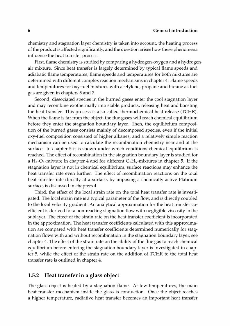
Figure 2.1 Representation of stagnation flame. u is the nozzle outlet velocity of the un-burned mixture, u the plug flow velocity of the burned mixture, sL the laminarburning velocity, x L the position of the burner outlet, x Htip the positionof the flame tip, x Hstag the outer edge of the stagnation zone, x Hstabthe equivalent position of a 1D-stagnation flame, and x the flat stagnationsurface.
2.4 This thesis
2.4.1 Assumptions
Figure 2.1 shows a representation of an axisymmetric or two-dimensional stagnationflame, as typically used in an industrial set-up. The unburned gas leaves the nozzleexit at x L with a velocity u. Depending on the burner geometry the velocityprofile varies between the shape of a plug flow and the shape of a fully developedflow. In this thesis it is assumed that the velocity profile at the burner outlet has theform of a plug flow. The gas is burned in a thin Λ-shaped or conic flame front, andthe stream tube is widened due to the expanding gases. The flame tip is at x Htip
and slightly above this position, the burned gases are at a constant temperature anddensity. The longitudinal velocity profile shows a nonuniformity for air-fuel flamesabove the flame tip [111]. However, oxy-fuel flames can be stabilized for a burneroutlet velocity u that is much higher than the laminar burning velocity sL. Then,the velocity profile of the burned gases has a shape which closely resembles a plugflow visualized by velocity u. The velocity of the plug flow is dependent on the
24 Chemically reacting stagnation flow
0 1000 2000 3000 4000 50000
1000
2000
3000
4000
5000
6000
u1 [cm/s]
u 2 [cm
/s]
sL < u
1 < τ⋅s
L u
1 > τ⋅s
L u
1 < s
L
u2 = τ⋅s
L
u2
u2 = u
1
u2 = s
L
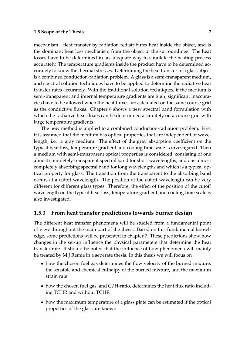
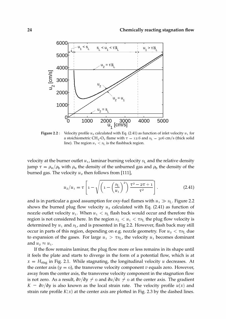
Figure 2.2 Velocity profile u calculated with Eq. (2.41) as function of inlet velocity u fora stoichiometric CH-O flame with τ . and sL cm/s (thick solidline). The region u < sL is the flashback region.
velocity at the burner outlet u, laminar burning velocity sL and the relative densityjump τ ρu/ρb with ρu the density of the unburned gas and ρb the density of theburned gas. The velocity u then follows from [111],
u/u τ
[
√
(
(
sL
u
))τ τ
τ
]
. (2.41)
and is in particular a good assumption for oxy-fuel flames with u sL. Figure 2.2shows the burned plug flow velocity u calculated with Eq. (2.41) as function ofnozzle outlet velocity u. When u < sL flash back would occur and therefore thisregion is not considered here. In the region sL < u < τsL the plug flow velocity isdetermined by u and sL, and is presented in Fig 2.2. However, flash back may stilloccur in parts of this region, depending on e.g. nozzle geometry. For u < τsL dueto expansion of the gases. For large u > τsL, the velocity u becomes dominantand u ≈ u.
If the flow remains laminar, the plug flow more or less remains in its shape untilit feels the plate and starts to diverge in the form of a potential flow, which is atx Hstag in Fig. 2.1. While stagnating, the longitudinal velocity u decreases. Atthe center axis (y ), the transverse velocity component v equals zero. However,away from the center axis, the transverse velocity component in the stagnation flowis not zero. As a result, ∂v/∂y 6 and ∂u/∂x 6 at the center axis. The gradientK ∂v/∂y is also known as the local strain rate. The velocity profile u
x and
strain rate profile Kx at the center axis are plotted in Fig. 2.3 by the dashed lines.

2.4 This thesis 25
−0.6 −0.4 −0.2 00
2000
4000u
[cm
/s]
x [cm]−0.6 −0.4 −0.2 0
0
5000
10000
15000
−0.6 −0.4 −0.2 00
5000
10000
15000H
tip H
stag H
stab
u2
τ⋅sL
sL
u
K
K [1
/s]
Figure 2.3 Velocity u and strain K profiles. The dashed lines give the profiles for a stag-nating plug flow calculated with Eqs (2.42) and (2.43). The solid lines give thereults from 1D numerical stagnation flame computations.
Due to the non-diverging plug flow the strain rate K for Htip ≤ x ≤ Hstag. Atx Hstag the flow enters the stagnation layer and starts to diverge and the strain rateincreases. The strain rate increases until viscous effects start to play a role. Due tothe no slip boundary condition at the stagnation surface, K at x . Remie [110]derived an expression for the strain rate of a stagnating planar inert flow,
Kx Km cos
( Kmx
δvisc/ u
,)
(2.42)
and by integration, an expression for the longitudinal velocity,
ux u sin
( Kmx
δvisc/ u
.)
(2.43)
with Km the maximum strain rate, which is equal to Km πu/Hstag and is alsorelated to the so-called applied strain rate a of the unburned mixture via Km τ/a.The viscous boundary layer thickness was derived as δvisc
ν/Km / with ν the
dynamic viscosity. The velocity and strain profiles are presented by the dashed linesin Fig. 2.3.
The same flow configuration can be modelled one-dimensionally. A flat one-dimensional flame is given in Fig. 2.1 by the thick dashed line. The one-dimensionalflame stabilizes at a position x Hstab, see Fig. 2.3. The position Hstab is approxi-mately the position of the flame front of the equivalent one-dimensional configura-tion where u τsL. In the region Htip ≤ x ≤ Hstab the strain rate is constant and

26 Chemically reacting stagnation flow
equal to the applied strain rate K a and the velocity profile has a linear shape withu sL at x Hstab. At x Hstab a thin flame front is formed and the burned fluegases reach a velocity approximately equal to τsL after the one-dimensional flamefront. The effective inlet velocity u
Htip follows from the applied strain rate and the
position uHstab where u sL. In approximately the region Hstab ≤ x ≤ , due to
the stagnating flow, the velocity decreases until it is zero at the stagnation plane, andthe strain rate increases until it is maximum at the edge of the viscous layer, fromwhere it goes to zero. If the flame is stabilized relatively far from the stagnationplane the maximum strain rate is close to Km τ/a. It can be concluded that thevelocity and strain profile of the one-dimensional configuration corresponds wellwith the velocity and strain profile of a stagnation flame as typically used in an in-dustrial set-up. At approximately x Hstab, they both possess a similar flow, andequal temperature and chemical composition. Therefore, the reacting stagnationflow can be simulated one-dimensionally.
In most lamp making production steps the typical width of the flame cone ismuch smaller than the target, and the angle of inclination of the stagnation flow isapproximately perpendicular to the target surface. As a result the stagnation surfacecan be considered flat within the radius of the stagnating jet. As long as the jet flowacts as a plug flow, the impinging jet can be considered one-dimensional. Far awayfrom the centeraxis, i.e. outside the jet radius, two-dimensional effects become im-portant, and the jet can not be considered one-dimensionally. However, in this thesiswe will focus on the region within the radius of the impinging jet where the stagna-tion surface can be considered flat and the flow can be considered one-dimensional.The shape of the jet also depends on the burner geometry. In this thesis only singlejets are studied, which can be axisymmetric or planar, depending on the geometry ofthe nozzle outlet. To conclude, a one-dimensional laminar premixed oxy-fuel flamestagnating to an infinite plate is studied in the remainder of this thesis. Further-more, in the chemically reacting stagnation flow, body forces bi, volume viscosity κ,volumetric heat input Q, Soret and Dufour diffusional effects, and gas radiation areneglected, as has been discussed in section 2.2.1. Due to the preferential diffusion inthe flame front non-unit Lewis numbers are taken into account. Furthermore, it isassumed that there is no bulk growth on the surface, and surface reactions reach asteady state rapidly, so that a Stefan velocity is absent.
2.4.2 Equations
Figure 2.4 shows the representation of a one-dimensional stagnation flame imping-ing a flat plate. The equations for a one-dimensional chemically reacting stagnationflow with the assumptions discussed in the previous section taken into account, are
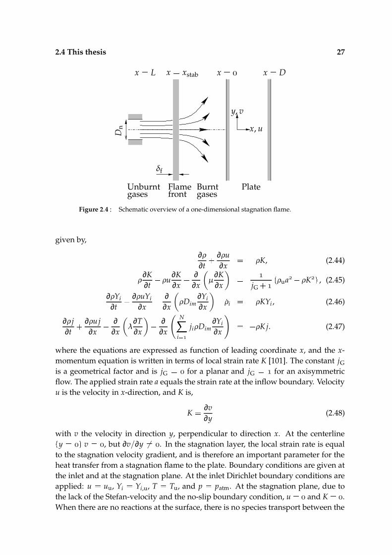
2.4 This thesis 27
x, u
y, v
Flamefront
Burntgases
Unburntgases
x
x Dx L
Plate
δf
x xstab
Dn
Figure 2.4 Schematic overview of a one-dimensional stagnation flame.
given by,
∂ρ
∂t ∂ρu
∂x ρK, (2.44)
ρ∂K∂t
ρu
∂K∂x ∂
∂x
(
µ∂K∂x
)
jG
ρua ρK , (2.45)
∂ρYi
∂t ∂ρuYi
∂x ∂
∂x
(
ρDim∂Yi
∂x
)
ρi ρKYi , (2.46)
∂ρ j∂t
∂ρuj∂x
∂∂x
(
λ∂T∂x
)
∂∂x
( N
i
jiρDim∂Yi
∂x
)
ρK j. (2.47)
where the equations are expressed as function of leading coordinate x, and the x-momentum equation is written in terms of local strain rate K [101]. The constant jGis a geometrical factor and is jG for a planar and jG for an axisymmetricflow. The applied strain rate a equals the strain rate at the inflow boundary. Velocityu is the velocity in x-direction, and K is,
K ∂v∂y
(2.48)
with v the velocity in direction y, perpendicular to direction x. At the centerliney v , but ∂v/∂y 6 . In the stagnation layer, the local strain rate is equal
to the stagnation velocity gradient, and is therefore an important parameter for theheat transfer from a stagnation flame to the plate. Boundary conditions are given atthe inlet and at the stagnation plane. At the inlet Dirichlet boundary conditions areapplied: u uu, Yi Yi,u, T Tu, and p patm. At the stagnation plane, due tothe lack of the Stefan-velocity and the no-slip boundary condition, u and K .When there are no reactions at the surface, there is no species transport between the
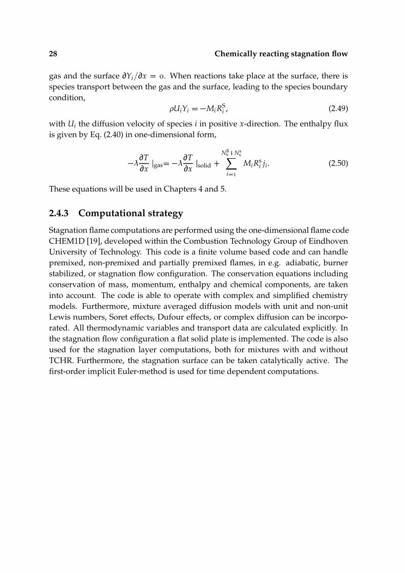
28 Chemically reacting stagnation flow
gas and the surface ∂Yi/∂x . When reactions take place at the surface, there isspecies transport between the gas and the surface, leading to the species boundarycondition,
ρUiYi MiRSi , (2.49)
with Ui the diffusion velocity of species i in positive x-direction. The enthalpy fluxis given by Eq. (2.40) in one-dimensional form,
λ∂T∂x
gas λ
∂T∂x
solid
Ng
s Nss
i
MiRsi ji. (2.50)
These equations will be used in Chapters 4 and 5.
2.4.3 Computational strategy
Stagnation flame computations are performed using the one-dimensional flame codeCHEM1D [19], developed within the Combustion Technology Group of EindhovenUniversity of Technology. This code is a finite volume based code and can handlepremixed, non-premixed and partially premixed flames, in e.g. adiabatic, burnerstabilized, or stagnation flow configuration. The conservation equations includingconservation of mass, momentum, enthalpy and chemical components, are takeninto account. The code is able to operate with complex and simplified chemistrymodels. Furthermore, mixture averaged diffusion models with unit and non-unitLewis numbers, Soret effects, Dufour effects, or complex diffusion can be incorpo-rated. All thermodynamic variables and transport data are calculated explicitly. Inthe stagnation flow configuration a flat solid plate is implemented. The code is alsoused for the stagnation layer computations, both for mixtures with and withoutTCHR. Furthermore, the stagnation surface can be taken catalytically active. Thefirst-order implicit Euler-method is used for time dependent computations.
Chapter3Heating of glass objects
Knowing the heating process of a glass is important for reasons of product through-put, and thermal stresses. Therefore, the transport of heat inside glass has to bemodelled accurately. In section 3.1 a general introduction is given of the differentphysical, chemical and optical properties of the glass and how they affect the heatingprocess. In section 3.2 the heating equations for an object of arbitrary form are given.Section 3.3 presents the corresponding boundary conditions, and in section 3.4 theassumptions and equations used in this thesis are postulated.
3.1 General introduction
In this section a description is given of the thermodynamics and optical propertiesof a glass. These properties have to be known in order to model the heating processof glass, including the redistribution of heat by conduction and radiative heat loss.
3.1.1 Chemical and thermodynamic properties
When being cooled, non-glass materials change phase from a liquid to a crystallinestate with a long range, periodic atomic arrangement. In contrast, a glass can bedefined as an amorphous solid completely lacking long range, periodic structureand exhibiting a region of glass transformation behavior [119]. The structure of aglass continuously rearranges as the temperature decreases. As a result, a glass canbe cooled below the melting temperature, without crystallization and becomes asupercooled liquid.
Although glass can be of any material, inorganic, organic, or metallic, silica isoften the main component. The production of silica glass (SiO), also known as vit-reous silica, fused silica, or (fused) quartz, is an energy consuming task, due to thehigh melting temperature (>2000 K), and so-called fluxes, mostly alkali oxides, aresometimes added to reduce the processing temperature. Borosilicate and alkaline-silicate glasses are regularly used in the lighting industry. However, in e.g. halo-gen incandescent lamps, high-pressure discharge lamps, and spectral lamps, purequartz glass is often used [104].
The density, specific heat capacity and thermal conductivity of the glass haveto be known to determine the typical heating and processing times, and can be
30 Heating of glass objects
found in e.g. [117]. The density of a glass is a strong function of its compositionand molecular structure, and to a lesser degree on the temperature and thermal his-tory [119]. The density of vitreous silica and α-quartz are . · kg/m [25] and. · kg/m [2] respectively.
The specific heat capacity of a glass is dependent on composition and tempera-ture. For vitreous silica, Kelley found [69] an expression for the specific heat capac-ity,
cvs .
. · T . · T , (3.1)
for the range from 298 K to 2000 K. This expression is in J/mol K, and conversion toJ/g K is achieved by dividing the expression with the molar mass of silica.
Conduction is the dominant internal heat transport mechanism at low temper-atures. In a solid material, heat transfer by conduction is carried out through theatomic lattice by free electrons or by phonon-phonon interactions, by means of ex-citation of vibrational energy levels for interatomic bonds [96]. In gases and liquids,the energy transfer is carried out through transfer of kinetic energy from fast to slowmolecules when they collide. Wray and Connolly [139] performed steady-state ex-periments and calculated thermal conductivities of vitreous silica to temperaturesup to approximately 2000 K. The experiments yielded thermal conductivities of 1.1-1.2 W/m K at room temperature, increasing roughly linear to 1.9 W/m K at 1000 Kand varying between 1.9 W/m K and 2.3 W/m K in the temperature range 1000-2100 K.
For the range from 300 to 2000 K, the density ρs remains nearly constant whileboth the specific heat capacity cvs and thermal conductivity λs increase approxi-mately with a factor of 2. As a result, the thermal diffusivity αs λs/ρscvs, which isan important parameter for the heating of an object, remains approximately constantwith increasing temperature. In this thesis the density, specific heat capacity andthermal conductivity are taken independent of temperature. The density is takenequal to . · kg/m. A specific heat capacity of J/kg K is chosen, whichcorresponds approximately to the heat capacity derived from Kelley’s expression atroom temperature. A thermal conductivity coefficient of 1.404 W/m K is used [109],and the thermal diffusivity equals αs · m/s.
3.1.2 Optical properties
At temperatures above about 600 K radiation effects become important [2]. Emis-sion and absorption of radiative heat leads to redistribution of heat inside the object,and heat loss from the object to the surroundings, and depends on the optical prop-erties of the object. The optical properties of a material are given by the absorptioncoefficient and the refractive index. For semi-transparent materials as glass, the ab-sorption coefficient and refractive index are wavelength selective. Fig 3.1 shows atypical absorption and refractive index curve for fused and vitreous silica glass atroom temperature. Semi-transparent materials are nearly transparent, or optically

3.2 Governing Equations 31
0 1 2 3x 10
−6
0
100
200
300
400
500
600
700
k λ [1/m
]
0 1 2 3x 10
−6
1.4
1.42
1.44
1.46
1.48
1.5
1.52
1.54
n rλ
nrλ kλ
Figure 3.1 Spectral absorption coefficient kλ of fused silica glass at 298 K [58] and refrac-tive index nrλ of vitreous silica glass at 299 K [138].
thin, for a selective region of the optical spectrum, while they are almost completelyabsorbing, or optically thick, for another region of the spectrum. The transition be-tween the spectral regions occurs at a certain cut-off wavelength. Ordinary glasseshave two cut-off wavelengths. For fused silica the cut-offs are typically in the farultraviolet λ ≈ . µm, and in the near infrared λ ≈ . µm [122]. In the regionbetween these cut-off wavelengths the glass is approximately transparent, while inthe short λ < . µm and long λ > . µm wavelength regions, glass is a strong ab-sorber or emitter. Therefore, the semi-transparency of the absorption curve can notbe neglected and is taken into account in the remainder of this thesis. The propaga-tion velocity of radiation in a medium is dependent on the refractive index, whichis also spectrally dependent. However, the spectral dependence is not very strongfor most glasses, and in this thesis the refractive index will be taken at a constantvalue of nr ., a typical value for vitreous silica or quartz glass. The equationsare presented in the next section, where the assumptions discussed in this sectionare taken into account.
3.2 Governing Equations
In this section the energy equations are presented for a solid material in vector no-tation. In section 3.2.1 the conservation equation of energy together with the heatfluxes are given. Radiative heat fluxes are treated seperately in section 3.2.2 becauseof their complex character.
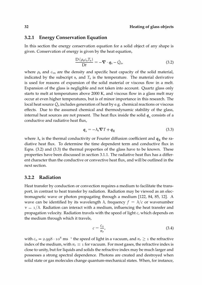
32 Heating of glass objects
3.2.1 Energy Conservation Equation
In this section the energy conservation equation for a solid object of any shape isgiven. Conservation of energy is given by the heat equation,
DρscsTs Dt
∇ · qs Qs, (3.2)
where ρs and cvs are the density and specific heat capacity of the solid material,indicated by the subscript s, and Ts is the temperature. The material derivativeis used for reasons of expansion of the solid material or viscous flow in a melt.Expansion of the glass is negligible and not taken into account. Quartz glass onlystarts to melt at temperatures above 2000 K, and viscous flow in a glass melt mayoccur at even higher temperatures, but is of minor importance in this research. Thelocal heat source Qs includes generation of heat by e.g. chemical reactions or viscouseffects. Due to the assumed chemical and thermodynamic stability of the glass,internal heat sources are not present. The heat flux inside the solid qs consists of aconductive and radiative heat flux,
qs λs∇T qR (3.3)
where λs is the thermal conductivity or Fourier diffusion coefficient and qR the ra-diative heat flux. To determine the time dependent term and conductive flux inEqns. (3.2) and (3.3) the thermal properties of the glass have to be known. Theseproperties have been discussed in section 3.1.1. The radiative heat flux has a differ-ent character than the conductive or convective heat flux, and will be outlined in thenext section.
3.2.2 Radiation
Heat transfer by conduction or convection requires a medium to facilitate the trans-port, in contrast to heat transfer by radiation. Radiation may be viewed as an elec-tromagnetic wave or photon propagating through a medium [122, 84, 85, 12]. Awave can be identified by its wavelength λ, frequency f λ/c or wavenumberν /λ. Radiation can interact with a medium, influencing the heat transfer andpropagation velocity. Radiation travels with the speed of light c, which depends onthe medium through which it travels,
c c
nr, (3.4)
with c . · ms the speed of light in a vacuum, and nr ≥ the refractiveindex of the medium, with nr ≡ for vacuum. For most gases, the refractive index isclose to unity, but for liquids and solids the refractive index may be much larger andpossesses a strong spectral dependence. Photons are created and destroyed whensolid state or gas molecules change quantum-mechanical states. When, for instance,

3.2 Governing Equations 33
φ
θ
i ′
λ
θ,φ
dω
dAN dAp
nN
s
Figure 3.2 schematic overview of a ray normal to a projected surface area dAp.
a gas molecule falls from a higher to a lower energy state, a photon is emitted withan energy equivalent to the difference in energy states. When a molecule absorpsa photon, it shifts from a lower to a higher energy state. Radiation has not only anenergy state, but also a direction. The direction can be changed without changingthe energy state, due to reflection at a surface or scattering inside a participatingmedia. Radiative heat transfer is therefore spatially, directionally and spectrallydependent, and calculating the radiative fluxes is a complex task.
Radiation is usually quantified in terms of the monochromatic radiative intensityi ′λ, which is the radiative energy flux per unit of wavelength, projected surface areaAp normal to the direction of the radiation, and per unit solid angle ω around thedirection s, as shown in Fig. 3.2. The radiative heat flux is obtained by integratingthe intensity weighted by the unit direction vector s over the whole spectrum andsolid sphere, and is given by the first moment of radiative intensity,
qR
π
i ′λx, s sdωdλ, (3.5)
with i ′λ the spectral intensity at position x in direction s, see Fig 3.2. The intensitychanges along a path s are caused by absorption, emission and scattering. Absorp-tion and emission alter the energy of the radiation without changing the direction,while scattering redirects the radiation isotropically or non-isotropically and in thisway alters the radiative intensity. The intensity decreases due to absorption by themedium, and due to away-scattering of some part of the radiation,
di ′λ kλ
σsλ i ′λds Kλi ′λds, (3.6)
with kλ, σsλ and Kλ the spectrally dependent absorption, scattering and extinc-tion coeffient. Integration of Eq. (3.6) yields the intensity after a path of length s,
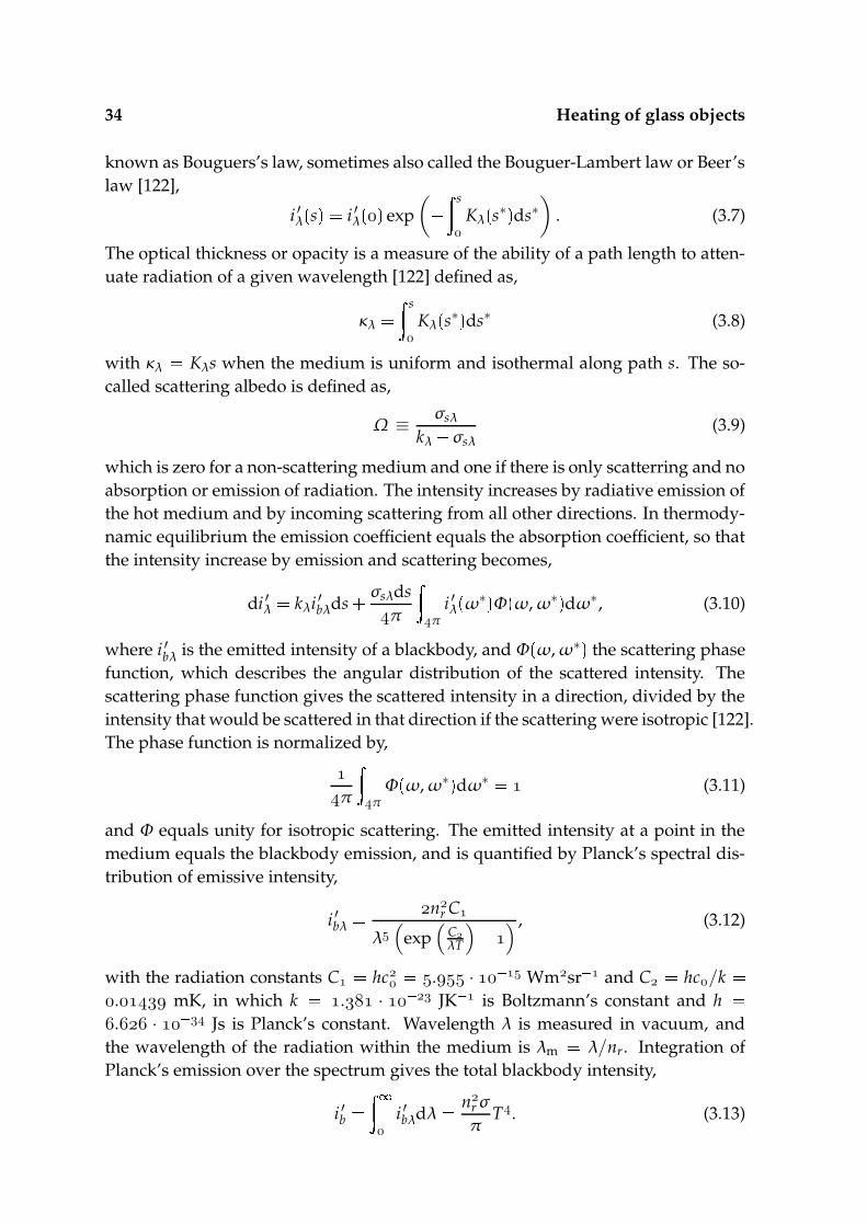
34 Heating of glass objects
known as Bouguers’s law, sometimes also called the Bouguer-Lambert law or Beer’slaw [122],
i ′λs i ′λ
exp
(
s
Kλ
s∗ ds∗
)
. (3.7)
The optical thickness or opacity is a measure of the ability of a path length to atten-uate radiation of a given wavelength [122] defined as,
κλ s
Kλ
s∗ ds∗ (3.8)
with κλ Kλs when the medium is uniform and isothermal along path s. The so-called scattering albedo is defined as,
Ω ≡ σsλ
kλ
σsλ(3.9)
which is zero for a non-scattering medium and one if there is only scatterring and noabsorption or emission of radiation. The intensity increases by radiative emission ofthe hot medium and by incoming scattering from all other directions. In thermody-namic equilibrium the emission coefficient equals the absorption coefficient, so thatthe intensity increase by emission and scattering becomes,
di ′λ kλi ′bλds σsλdsπ
π
i ′λω∗ Φ ω, ω∗ dω∗, (3.10)
where i ′bλ is the emitted intensity of a blackbody, and Φω, ω∗ the scattering phase
function, which describes the angular distribution of the scattered intensity. Thescattering phase function gives the scattered intensity in a direction, divided by theintensity that would be scattered in that direction if the scattering were isotropic [122].The phase function is normalized by,
π
π
Φω, ω∗ dω∗ (3.11)
and Φ equals unity for isotropic scattering. The emitted intensity at a point in themedium equals the blackbody emission, and is quantified by Planck’s spectral dis-tribution of emissive intensity,
i ′bλ n
r C
λ(
exp(
CλT
)
) , (3.12)
with the radiation constants C hc . · Wmsr and C hc/k
. mK, in which k . · JK is Boltzmann’s constant and h . · Js is Planck’s constant. Wavelength λ is measured in vacuum, andthe wavelength of the radiation within the medium is λm λ/nr. Integration ofPlanck’s emission over the spectrum gives the total blackbody intensity,
i ′b
i ′bλdλ nrσ
πT. (3.13)

3.3 Boundary Conditions 35
with σ Cπ / C
. · Wm K the Stefan-Boltzmann con-stant. The radiative transfer equation (RTE) is obtained from a combination ofEqns. (3.6) and (3.10),
di ′λds kλ
σsλ i ′λ kλi ′bλ
σsλ
π
π
i ′λω∗ Φ ω, ω∗ dω∗. (3.14)
If the scattering and absorption coefficients are independent of wavelength, themedium is called gray. Although the gray assumption is often used, real media be-have very seldom as a gray medium. Glass can not be considered as a gray mediumdue to the semi-transparent character. Scattering in a glass or glass melt occurs onlyif either there are gas bubbles in the melt, or if the melt is not completely moltenso that small spherical particles are present [85]. However, this is not observed inthe lamp making process and scattering is neglected, i.e. σsλ . Then Eq. (3.14)simplifies to,
di ′λds kλ
(
i ′λ i ′bλ
)
. (3.15)
This is the intensity change along a path s in any direction s and around point x.Finally, Eq (3.15) can be integrated along a pathlength s, which gives the formalsolution,
i ′λs i ′λ
exp
kλS s
s∗ kλi ′bλ
s∗ exp
kλ
s s∗ ds∗. (3.16)
This equation is used in the discrete transfer method.
3.3 Boundary Conditions
To solve the energy conservation equation, Eq. (3.2), boundary conditions have tobe applied at the surfaces. The boundary condition at a surface of the object is abalance between the convective heat transport from the surroundings to the object,the conductive heat flux into the object and the radiative heat loss from the object tothe surroundings,
λnn ·∇T
solid FT nn · qR, (3.17)
where nn again points into the object, see Fig. 3.3 (left). The convective heat inputis given by an arbitrary function F
T , which can be a function of surface tempera-
ture. Often surface emission is used as radiation boundary condition. However, inprinciple the radiation is emitted within the whole object and part of the radiationleaves the object at the walls, while another part of the radiation is reflected backinto the object at the surface due to specular reflection. Specular reflection occurs atan optically smooth interface between two nonattenuating, perfect dielectric, mate-rials with different refraction indices. The radiative heat flux normal to the surface(
nn · qR)
is negative when there is a radiative heat flux from the object to the sur-roundings. The directional radiative heat flux is calculated with Eq. (3.5), once the

36 Heating of glass objects
θ
µ
s
xnN
x
n
θr
θ
n
ρ ′ i ′
λ
χ
ρ ′i ′
λ
i ′
λ
Figure 3.3 Definition of directional variables (left) and transmission and reflection of abeam striking an intersection of two media with different refractive indices(right).
spectal intensities at the surface are determined. Let µ nN · s be the fraction ofthe intensity of a beam in direction s in normal direction nN, represented in Fig. 3.3(left), so that radiation with direction ≤ µ < propagates from inside the objecttowards the surface. Since it is assumed that there is no radiation from the surround-ings into the object, the intensity of radiation with direction ≤ µ ≤ is equal tothe intensity of a reflected beam,
i ′λµ ρ ′ µ i ′λ
µ . ≤ µ ≤ , (3.18)
The directional-hemispherical spectral reflectivity ρ ′ for an unpolarized ray is givenby the Fresnel equation for specular reflection [122],
ρ ′ µ
sin θ χ sin θ
χ [
cos θ
χ cos
θ χ
]
(3.19)
with θ arccos µ the angle of incidence with the surface normal of a ray prop-
agating through a medium with refractive index n, and χ the angle of the beam ifit is transmitted in a medium with refractive index n, as presented in 3.3 (right).According to Snell’s law,
sin χ
sinθ n
n. (3.20)
With the intensities known, the radiative heat flux at the boundary is calculated withEq. (3.5).
3.4 This thesis
3.4.1 Assumptions
A lamp part often has the shape of a tube with a thin shell. If the typical radius ofthe tube (in practice of the order of m) is much larger than the shell thickness

3.4 This thesis 37
x, uy, v
Plate
x D
i ′
λ
µ
n
N nDN
s
qR
qcond
StagnationFlow
x
Figure 3.4 Schematic overview of the heat transfer in a one-dimensional plate, with qRand qcond the radiative and conductive heat fluxes in direction x, and n
N andnD
N the surface normals at x and x D.
(in practice of the order of - m), then the shell can be modelled as a flatplate. Furthermore, if the width of the impinging hot jet (in practice of the order of m) is large compared to the plate thickness, the temperature profile in the plateis approximately one-dimensional. Therefore, in this thesis we have chosen to studythe heating of a infinite one-dimensional flat plate. As discussed in section 3.2.1expansion is neglected and chemical reactions or viscous flow inside the glass is nottaken into account. One surface of the plate is heated by an external convective heatflux due to a hot chemically reacting stagnation flow. The other surface exhibits anegligible or natural convective heat loss. The plate suffers from radiative heat lossat both surfaces. Obviously, quartz glass has semi-transparent optical properties,being almost transparent for short wavelengths . < λ < . µm, and almostcompletely absorbing for long wavelengths λ > µm. Band models with a constantabsorption coefficient in each band are used. Scattering is in general not observedin the production process of lamp parts, and is therefore not taken into account.
3.4.2 Equations
The energy equation for a one-dimensional infinite plate is a function of leadingcoordinate x in direction n
N,
ρscvs∂Ts
∂t ∂
∂x
(
λs∂Ts
∂x qR
)
(3.21)
with qR the radiative heat flux in x-direction, i.e. qR nN · qR. The radiative heat
flux qR is calculated using Eq. (3.5) where s is defined with respect to the x-axis, and

38 Heating of glass objects
µ nN · s so that qR becomes,
qR
π
i ′λx, µ µdωdλ. (3.22)
The local spectral intensity i ′λ is calculated using the formal solution of the radiativetransfer equation, Eq. (3.16). Boundary conditions have to be applied for the tem-perature and intensity at both surfaces. The boundary condition for the temperatureis given by,
λs∂T∂x FT qR, (3.23)
At x the function FT is given by the convective heat flux of a stagnating flow.
At x D, in some cases convection is neglected, FT , and in some cases the
function has a typical form of hcT Tamb , with hc the heat transfer coefficient.
The boundary condition for the radiative intensity is derived from Eq. (3.18). Thereflecting boundary conditions for the intensities at the surfaces are,
i ′λ, µ ρ ′ µ i ′λ
, µ (3.24)
i ′λD, µ ρ ′ µ i ′λ
, µ (3.25)
for ≤ µ ≤ .
3.4.3 Computational strategy
Radiation computations in a flat plate are performed with a one-dimensional finitevolume based numerical code. For the spatial discretization an equidistant meshis used. The radiative heat fluxes at the boundaries of each spatial element are ob-tained from numerical integration over the spherical domain by using the discreteordinates method. The discrete ordinates method discretizes the solid angle in anumber of ordinates with uniform optical properties and intensity in each ordinate.The intensities, needed for the discrete ordinates method, are determined using thediscrete transfer method. In the discrete ordinate method, the intensity of a ray istraced while traveling through the considered geometry. A more extensive expla-nation of the discrete ordinates method and discrete transfer method is given inchapter 6, and can be found in various literature, e.g. [122, 96] The plate is consid-ered semi-transparent with varying spectral absorption curve. Therefore, spectraldiscretization is needed. A band model, in which the absorption coefficient is con-sidered constant within such a band, is used. Since a glass has a non-unit refractionindex, non-unit refraction indices, with Fresnel boundary conditions are taken intoaccount where the refraction index is taken spectrally independent. The first-orderimplicit Euler-method is used for time dependent computations.
Chapter4Heat transfer mechanisms oflaminar flames ofhydrogen+oxygen
Abstract
Increasing the heat transfer from premixed laminar oxy-fuel flames to glass or quartzproducts is of major importance in the lighting industry. In this paper a laminarhydrogen-oxygen flame is used as an impinging jet in a stagnation-flow like con-figuration to investigate the heating of a glass product. The research is intended toanalyse the crucial phenomena determining the heat transfer rate. The time scalesof the processes taking place in the flame, the stagnation boundary layer and theplate are quantified and from this it is shown that these zones can be decoupled. Itwill also be shown that as a result, the heat flux entering the plate only depends onthe stagnation flow and plate surface temperature. Two cases are studied. In onecase the stagnation boundary layer consisting of a burned and chemically frozenhydrogen-oxygen or hydrogen-air mixture is studied. In the other case the flow isreactive in the stagnation boundary layer. An analytical approximation for the heattransfer coefficient is derived for the case without viscous sublayer. The effect ofstrain rate on the heat transfer coefficients is incorporated in this model. This heattransfer coefficient is compared to numerically calculated heat transfer coefficientsfor stagnation flows with both reactive and non-reactive boundary layers. Further-more, it is shown that the stagnation boundary layer is not in chemical equilibrium.First numerical results indicate that surface chemistry can be expected to contributesignificantly to the heating process. Surface chemistry is studied numerically byassuming a quartz plate coated with a platinum layer.
This chapter has been published as: M.F.G. Cremers, M.J. Remie, K.R.A.M. Schreel, L.P.H. deGoey, Heat Transfer Mechanisms of Laminar Hydrogen + Oxygen Flames, Combust. Flame,139(1-2) (2004) 39-51K.
40 Heat transfer mechanisms of laminar flames of hydrogen+oxygen
4.1 Introduction
Mixtures of a fuel and oxygen are used for many industrial processes. Oxy-fuelflames are used for welding and cutting purposes, and also for coating processes [114].High velocity oxy-fuel (HVOF) spraying has been successfully optimized for the de-position of BaTiO as dense thick (25-150 µm) dielectric layers [34]. Apart from theseprocesses, oxy-fuel combustion is also used for the heating of products. Heatingwith oxy-fuel combustion in many cases has both environmental and cost reduc-tions benefits, as for example in the steel industry [43]. In the steel and glass indus-try, a high energy input is needed for melting purposes. For this reason high temper-ature oxy-fuel flames are used. Premixed oxy-fuel burners convert chemical energyinto thermal energy rapidly. The fast conversion results in high flame speeds andheat transfer rates. Moreover, the lack of nitrogen in the premixed gas may reducethe nitrogen oxide (NOx) formation considerably. For glass melting in industrialovens [140], hydrogen-oxygen mixtures are commonly used [133]. The reduction inenergy consumption is considerable when recuperative ovens are replaced by oxy-fuel ovens [133]. Since the late sixties and early seventies the lighting industry hasbeen using premixed oxy-fuel combustion. High heat transfer rates leading to shortprocessing times were the main reasons for the introduction of oxy-fuel combustion.Short processing times are needed for both a high product throughput and quality.In the lamp making process the heat has to be applied very locally. Therefore, oxy-fuel flames in an impinging-jet like configuration are often used. Impinging laminarand turbulent jets have been well studied. Especially the heat transfer from inert gasjets to stagnation walls is well known [91], [62], [61]. Oxy-fuel flames are small andmostly laminar. Little is known about impinging laminar jets consisting of premixedoxy-fuel flames.
For the lighting industry, to be able to reduce the costs and to enhance the effi-ciency, more knowledge has to be gained on the mechanisms of heat transfer fromsuch oxy-fuel flame jets to the glass products. The purpose of the research discussedin this paper is to gain knowledge on the heat transfer mechanisms from small, highspeed, laminar, oxy-fuel flames to glass products for lamp manufacturing. In thispaper a hydrogen-oxygen flame is used as an impinging jet in a stagnation-flow likeconfiguration. It is intended to analyse the crucial heat transfer phenomena in orderto formulate new design rules for the optimization of the heat transfer.
It is anticipated that not only the transport of heat by convection and conduc-tion affects the heat transfer in oxy-fuel flames, but that the production of heat bychemistry effects has a significant influence as well. These very hot flames containconsiderable quantities of free radicals like O, OH and H that might recombine inthe cold stagnant boundary layer near the product, releasing chemical energy andboosting the heat transfer (of the order of J/g mixture). Also recombina-tion reactions of species adsorbed on the product surface might influence the heattransfer rate. The importance of these different mechanisms is investigated here.

4.1 Introduction 41
x, u
y, v
Flamefront
Burntgases
Unburntgases
x x Dx L
Plate
δf
x xstab
Dn
Figure 4.1 Schematic overview of a stagnation flame. Dn is the nozzle diameter. L isthe distance from the nozzle outlet to the plate surface. δf is the flame frontthickness and xstab is the position of the flame front.
It will be assumed in the current study that the burner is close to the productsurface so that the distance from the flame to the product is small compared to thetypical width of the jet of combusted gases. The configuration in this case can beconsidered as a one-dimensional reacting stagnation flow issuing on a flat plate, seeFig. 4.1. The heat transfer phenomena within this configuration are studied analyti-cally and numerically in this paper. Experiments are in progress.
The focus of this study is on high temperature hydrogen-oxygen flames. Mix-tures of hydrogen and air are discussed as well, so that a comparison can be madebetween the observed phenomena in oxy-fuel and air-fuel flames. In this study onlythe thermodynamical properties of quartz will be taken into account since quartzis the main component in lamp glasses and needs the highest heat transfer rate tomelt.
In the next section the computation geometry will be presented, together withthe conservation equations and boundary conditions for the reacting stagnant flow,for the quartz plate and the inclusion of surface chemistry effects. In section 4.3, atime scale analysis will be performed for the typical time scales of (1) the heat pro-duction in the reaction layer of the flame and (2) the heat transport by convection.Section 4.4 gives the typical time scale for the heating of a quartz glass product. Sec-tion 4.5 discusses the heat transfer from a burned gas to the product when no chem-ical reactions take place in the stagnant boundary layer. Afterward in section 4.6,the effect of recombination reactions in the boundary layer on the heat transfer rateto the product is determined. In section 4.7 it will be shown that the reacting stagna-
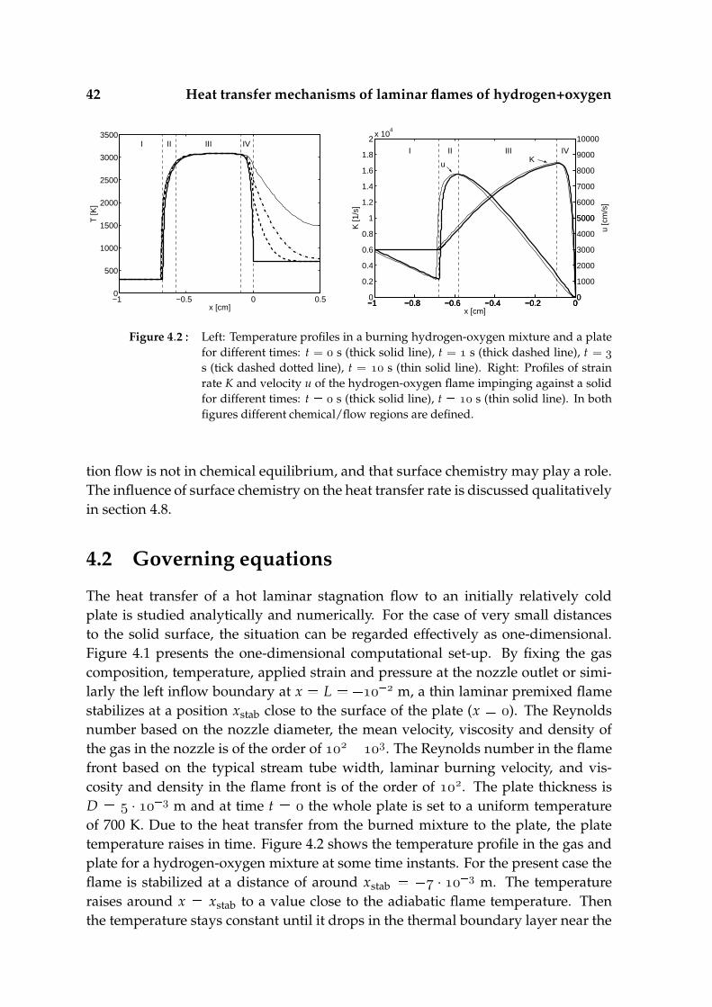
42 Heat transfer mechanisms of laminar flames of hydrogen+oxygen
−1 −0.5 0 0.50
500
1000
1500
2000
2500
3000
3500
x [cm]
T [K
]
I II III IV
−1 −0.8 −0.6 −0.4 −0.2 00
0.2
0.4
0.6
0.8
1
1.2
1.4
1.6
1.8
2x 10
4
K [1
/s]
x [cm]
I II III IV
uK
−1 −0.8 −0.6 −0.4 −0.2 00
5000
10000
u [c
m/s
]
−1 −0.8 −0.6 −0.4 −0.2 00
1000
2000
3000
4000
5000
6000
7000
8000
9000
Figure 4.2 Left: Temperature profiles in a burning hydrogen-oxygen mixture and a platefor different times: t s (thick solid line), t s (thick dashed line), t s (tick dashed dotted line), t s (thin solid line). Right: Profiles of strainrate K and velocity u of the hydrogen-oxygen flame impinging against a solidfor different times: t s (thick solid line), t s (thin solid line). In bothfigures different chemical/flow regions are defined.
tion flow is not in chemical equilibrium, and that surface chemistry may play a role.The influence of surface chemistry on the heat transfer rate is discussed qualitativelyin section 4.8.
4.2 Governing equations
The heat transfer of a hot laminar stagnation flow to an initially relatively coldplate is studied analytically and numerically. For the case of very small distancesto the solid surface, the situation can be regarded effectively as one-dimensional.Figure 4.1 presents the one-dimensional computational set-up. By fixing the gascomposition, temperature, applied strain and pressure at the nozzle outlet or simi-larly the left inflow boundary at x L m, a thin laminar premixed flamestabilizes at a position xstab close to the surface of the plate (x ). The Reynoldsnumber based on the nozzle diameter, the mean velocity, viscosity and density ofthe gas in the nozzle is of the order of . The Reynolds number in the flamefront based on the typical stream tube width, laminar burning velocity, and vis-cosity and density in the flame front is of the order of . The plate thickness isD · m and at time t the whole plate is set to a uniform temperatureof 700 K. Due to the heat transfer from the burned mixture to the plate, the platetemperature raises in time. Figure 4.2 shows the temperature profile in the gas andplate for a hydrogen-oxygen mixture at some time instants. For the present case theflame is stabilized at a distance of around xstab · m. The temperatureraises around x xstab to a value close to the adiabatic flame temperature. Thenthe temperature stays constant until it drops in the thermal boundary layer near the

4.2 Governing equations 43
plate, where the flow stagnates to the plate.In this section the equations describing this 1D chemically reacting flow are for-
mulated. The energy conservation equation for the plate will then be discussed.The boundary conditions and the equations coupling the gas to the solid phase willalso be given. Finally it will be discussed how the boundary conditions have to bemodified to take heterogeneous surface reactions into account.
The conservation equations for the reacting gas mixture include conservationof mass, momentum and enthalpy in a one-dimensional configuration. Figure 4.1shows this configuration. The density ρ, species mass fractions Yi, temperature Tand enthalpy j only depend on the leading coordinate x. The y-velocity componentv and the pressure however, depend on x and y. On the centerline (y ) v
but ∂v/∂y 6 . To take this derivative into account a local strain rate K is intro-duced [101]. K depends on x and time only, and if the distance L is small comparedto the jet width K is such that:
v Ky. (4.1)
The conservation of mass is expressed by the continuity equation [136],
∂ρ
∂t ∂ρu
∂x ρK, (4.2)
where u is the local velocity component in x direction. ρK describes the loss of massin perpendicular direction (y) due to the stagnating flow. In the one-dimensionalstagnation flame the y-momentum equation reduces to an effective equation for thestrain rate (see e.g. [101] and [126]):
ρ∂K∂t
ρu
∂K∂x ∂
∂x
(
µ∂K∂x
)
jG
ρua ρK , (4.3)
where jG for a planar and jG for an axisymmetric flow. K a equals thestrain rate at the inflow boundary (x L) and µ is the viscosity. In a chemicallyreacting flow, a conservation equation for every species i has to be solved
∂ρYi
∂t ∂ρuYi
∂x ∂
∂x
(
ρDim∂Yi
∂x
)
ρi ρKYi , (4.4)
with Dim the effective diffusion coefficient, which is calculated using a mixture aver-aged diffusion model [53], [41]. Furthermore, the chemical source term is quantifiedby ρi Mi
k νikωk where Mi is the molar mass of species i, νik the stoichiometric
coefficient of species i in reaction k, and ωk the reaction rate of reaction k. The en-ergy conservation equation for the gas is written in terms of the specific enthalpy jand temperature T:
∂ρ j∂t
∂ρuj∂x
∂∂x
(
λ∂T∂x
)
∂∂x
( N
i
jiρDim∂Yi
∂x
)
ρK j. (4.5)
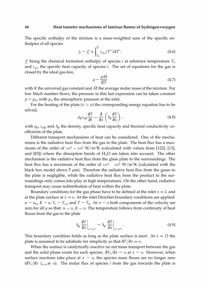
44 Heat transfer mechanisms of laminar flames of hydrogen+oxygen
The specific enthalpy of the mixture is a mass-weighted sum of the specific en-thalpies of all species
ji ji T
T
cp,iT∗ dT∗, (4.6)
ji being the chemical formation enthalpy of species i at reference temperature T
and cp,i the specific heat capacity of species i. The set of equations for the gas isclosed by the ideal gas-law,
ρ pMRT
(4.7)
with R the universal gas constant and M the average molar mass of the mixture. Forlow Mach number flows, the pressure in this last expression can be taken constantp pu, with pu the atmospheric pressure at the inlet.
For the heating of the plate (x > ) the corresponding energy equation has to besolved,
ρpcpp∂T∂t ∂
∂x
(
λp∂T∂x
)
, (4.8)
with ρp, cpp and λp the density, specific heat capacity and thermal conductivity co-efficients of the plate.
Different transport mechanisms of heat can be considered. One of the mecha-nisms is the radiative heat flux from the gas to the plate. The heat flux has a max-imum of the order of W/mK (calculated with values from [122], [13],and [83]) where the absorption bands of HO are taken into account. The othermechanism is the radiative heat flux from the glass plate to the surroundings. Theheat flux has a maximum of the order of W/mK (calculated with theblack box model above 5 µm). Therefore the radiative heat flux from the gases tothe plate is negligible, while the radiative heat flux from the product to the sur-roundings only comes into play at high temperatures. On the other hand, radiativetransport may cause redistribution of heat within the plate.
Boundary conditions for the gas phase have to be defined at the inlet x L andat the plate surface at x . At the inlet Dirichlet boundary conditions are applied:u uu, K a, Yi Yi,u and T Tu. At x both components of the velocity arezero for all y so that: u , K . The temperature follows from continuity of heatfluxes from the gas to the plate
λg∂T∂x
∣
∣
∣
∣
x
λp∂T∂x
∣
∣
∣
∣
x
. (4.9)
This boundary condition holds as long as the plate surface is inert. At x D theplate is assumed to be adiabatic for simplicity so that ∂T/∂x .
When the surface is catalytically inactive no net mass transport between the gasand the solid phase exists for each species: ∂Yi/∂x at x . However, whensurface reactions take place at x , the species mass fluxes are no longer zero(∂Yi/∂x
x 6 ). The molar flux of species i from the gas towards the plate is
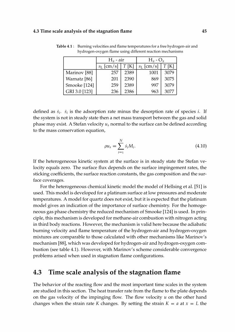
4.3 Time scale analysis of the stagnation flame 45
Table 4.1 Burning velocities and flame temperatures for a free hydrogen-air andhydrogen-oxygen flame using different reaction mechanisms
H - air H - O
sL [cm/s] T [K] sL [cm/s] T [K]Marinov [88] 257 2389 1001 3079Warnatz [86] 201 2390 869 3075Smooke [124] 259 2389 997 3079GRI 3.0 [123] 236 2386 963 3077
defined as si. si is the adsorption rate minus the desorption rate of species i. Ifthe system is not in steady state then a net mass transport between the gas and solidphase may exist. A Stefan velocity us normal to the surface can be defined accordingto the mass conservation equation,
ρus N
i
siMi . (4.10)
If the heterogeneous kinetic system at the surface is in steady state the Stefan ve-locity equals zero. The surface flux depends on the surface impingement rates, thesticking coefficients, the surface reaction constants, the gas composition and the sur-face coverages.
For the heterogeneous chemical kinetic model the model of Hellsing et al. [51] isused. This model is developed for a platinum surface at low pressures and moderatetemperatures. A model for quartz does not exist, but it is expected that the platinummodel gives an indication of the importance of surface chemistry. For the homoge-neous gas phase chemistry the reduced mechanism of Smooke [124] is used. In prin-ciple, this mechanism is developed for methane-air combustion with nitrogen actingin third body reactions. However, the mechanism is valid here because the adiabaticburning velocity and flame temperature of the hydrogen-air and hydrogen-oxygenmixtures are comparable to those calculated with other mechanisms like Marinov’smechanism [88], which was developed for hydrogen-air and hydrogen-oxygen com-bustion (see table 4.1). However, with Marinov’s scheme considerable convergenceproblems arised when used in stagnation flame configurations.
4.3 Time scale analysis of the stagnation flame
The behavior of the reacting flow and the most important time scales in the systemare studied in this section. The heat transfer rate from the flame to the plate dependson the gas velocity of the impinging flow. The flow velocity u on the other handchanges when the strain rate K changes. By setting the strain K a at x L the

46 Heat transfer mechanisms of laminar flames of hydrogen+oxygen
effective inlet velocity uu is prescribed. The applied strain rate a is chosen on thebasis of the velocity at the inlet, the laminar burning velocity, the distance from theinlet at x L to the flame front at x xstab and the distance from the flame frontto the plate surface at x (see Fig. 4.1). In Fig. 4.2 the behavior of K and u isconsidered. Roughly four regions can be distinguished. Close to the inlet (region I)the mixture is unburned, so that the strain rate K a is constant and the velocitydecreases linearly from the boundary value to a value close to the burning velocitynear the position where the flame front stabilizes in the flow. When the gas entersthe combustion zone (region II) the strain rate is not constant anymore due to thedensity gradient in the flame. The resulting K can be derived from Equation 4.3.Once the gas is burned it approaches chemical equilibrium (region III). If the flame isstabilized relatively far from the stagnation plane compared to the flame thickness,K does not change in time and space anymore and the asymptotic value for K canbe derived again from Equation 4.3. Assuming that K approaches a constant value,it follows that the strain rate of the mixture in the burned gases is given by
Km a(
ρu
ρm
)/
, (4.11)
where ρm is the density of the burned gases. ρm is equal to the density of an adiabaticequilibrium mixture in case of fast chemistry (hydrogen/oxygen), but this value isnot always reached if the chemical processes are slower (hydrogen/air).
Rogg and Peters [126] have shown that K changes in the form of a cosine in theburned gases approaching the stagnation plane in case of an opposed twin flamegeometry. This is also the case in the present geometry (region III), except for theregion almost at the surface of the plate, where the viscous boundary layer affectsthe velocity profile. In the stagnation boundary layer (region IV) the strain rate de-creases again. At the stagnation plane the strain rate equals zero because at x thevelocity component parallel to the plate v is zero for all y. Equation (4.11) indicatesthat the strain rate which determines the heat transfer to the plate is dependent onthe applied strain rate a and on the density of the burned gases ρm, which in turndepends on whether the burned gases reach chemical equilibrium or not. The strainrates for hydrogen-oxygen mixtures are higher than for hydrogen-air mixtures be-cause the typical burning velocities for hydrogen-oxygen mixtures are much greater.The hydrogen-oxygen mixtures are studied with applied strain rates of 6000, 8000and 10000 s . The hydrogen-air mixtures have applied strain rates of 2000, 4000and 6000 s .
In the remainder of this section, a time scale analysis for the different heating pro-cesses in the flame front (region II) and in the stagnation boundary layer (region IV)will be presented in order to judge the importance of the different processes [109].To do this the much simpler situation of an inert flow stagnating on a plate is con-sidered.
The chemical time scale of a flame front is typically τf δf/sL, where δf is the

4.4 Time scale analysis for the quartz glass product 47
flame front thickness and sL the burning velocity. The typical time scale for theheating of the inert boundary layer τb is determined by convective heating. In thiscase, the time scale is entirely determined from the strain rate in the flow: τb /Km. The strain rate of a hydrogen-oxygen mixture is of the order s , soτb
s.It is assumed that the typical flame front thickness is much thinner than the
distance from the plate to the flame front: δf xf. For this situation, it can beshown that the chemical time scale of the flame is much smaller than the timescale of the boundary layer. Therefore it is assumed that in an inviscid stagna-tion flow the velocity decrease is approximately linear (u ≈ Kmx). ThereforeKm ≈ um/xf, with um the gas velocity in the burned gases of the flame, and thusτb /Km ≈ xf/um
xf/sL ρu/ρb , which is larger than τf δf/sL. The
properties of the gas are assumed to be constant and thus the thermal diffusivityαg λg/ρgcpg is constant. An estimate for the flame thickness is δf αg/sL so thatthe typical chemical reaction time scale is τf αg/s
L. In a hydrogen-oxygen flameat 3079 K, αg . · m/s. With sL . m/s, τf
s. As expectedτf τb.
4.4 Time scale analysis for the quartz glass product
Another limiting time scale is the typical heat-up time scale of the plate. To deter-mine this time scale the heat balance between the quasi-steady stagnation flow andthe time-dependent behavior of the plate is studied. It is assumed that the gas con-sists of a single chemical component. With this assumption, the stationary enthalpyequation for the stagnation flow, Eq. (4.5), reduces to an equation in which onlythermal convection and diffusion is taken into account, if the stationary continuityequation, Eq. (4.2), is implemented. Viscosity of the stagnation flow is neglectedagain, so that K ≈ Km near the surface. If furthermore it is assumed that the specificheat capacity, thermal conductivity and density are independent of temperature, theone-dimensional steady energy equation for the stagnation flow becomes
κx∂T∂x ∂T
∂x
x < (4.12)
with κ ρgcpgKm/λg. It can be derived from Equation (4.12) by integrating twiceand inserting boundary condition (4.9) that the temperature gradient in the plate atthe interface is equal to
∂T∂x
∣
∣
∣
∣
x T Tm
(κ
π
)/(
λg
λp
)
, (4.13)
where Tm is the temperature at x , which is the temperature of the burned mix-ture. Equation (4.13) is used as boundary condition for the energy equation of theplate. For the heat-up time scale of the plate, the one-dimensional time-dependent

48 Heat transfer mechanisms of laminar flames of hydrogen+oxygen
energy Equation (4.8) is considered. If the thermal conductivity coefficient λp, thespecific heat capacity cpp and the density ρp of the plate are chosen to be temper-ature independent then the thermal diffusivity is defined as αp λp/ρcpp and theenergy equation inside the plate becomes
αp
∂T∂t ∂T
∂x,
x > . (4.14)
This differential equation is solved using separation of variables, which results in asolution of the form
Tx, t
C cos
kx D sin
kx exp
kαpt (4.15)
where C, D and k are constants which have to be determined from the boundary andinitial conditions. From the exponent in Equation (4.15) it follows that the typicalheat-up time scale of the plate is τp /kαp. The values of k are found withthe boundary condition (4.13) at x , the adiabatic boundary condition at x D and the initial condition which supposes that the plate is initially at a uniformtemperature T. Then one can show that k can be derived from
kD tankD ξD. (4.16)
with ξ λg/λpκ/π /. There is an infinite number of possible k values and
the solution (4.15) is a linear combination of all contributions. Small values of kindicate the slowest time scales, while large values of k give the fast scales duringthe initial phase of the heating process. From Equation (4.15) it follows that the fasttime scales are rapidly exhausted and the smallest k value is a measure for the timescale of the heating process of the complete plate. The smallest value of k is such that( < kD < π/). For the glass plate the thermal conductivity coefficient is λp .W/mK, the specific heat capacity cpp J/kgK and the density ρp . ·
kg/m. Therefore, αp . · m/s. Typical plate thicknesses are of the order m or larger. A typical maximum strain rate for a hydrogen-oxygen flame is. · s . For a gas temperature at the plate of 1500 K, the thermal conductivitycoefficient is λg . W/mK, the specific heat capacity cpg J/gK and thedensity ρg . kg/m, αg . · ms and thus ξ m . Whenthe plate thickness is D · m, k m and τp s. When the platethickness is D · m, k m and τp . s. Thus, for plate thicknessesof the order of millimeters τp is of the order seconds. We may conclude from thisexercise that the heat up time scale of the plate is much larger than the typical timescale of the boundary layer and the flame (τp τb τf). Because these time scalesdiffer significantly, the heating process of the plate and gas can be decoupled if theplate is more than a millimeter thick. For each value of the surface temperatureT the solution of the gas equations adapts very quickly and is very fast in quasi-
steady state. The heat flux from the gas to the plate is therefore independent of the

4.4 Time scale analysis for the quartz glass product 49
500 1000 1500 2000 2500 3000 35000
50
100
150
200
250
300
T(0) [K]
q [W
/cm
2 ]
D = 5.0 mmD = 1.0 mmD = 0.2 mm
Figure 4.3 Heat input of a hydrogen-oxygen flame to a plate as function of surface tem-perature for different plate thicknesses: D mm (solid line), D mm(dashed line), D . mm (dashed-dotted line).
temperature profile in the plate, but depends only on the temperature profile of theboundary layer and thus only in a quasi-steady manner on the surface temperature:q q
T . So the heat-flux to the plate q can be determined by computing the
gas temperature profile, for each value of the interface temperature T without
considering the heating of the solid phase. Stimulated by Equation (4.13) we nowwrite q h
T Tm where Tm is the maximum temperature of the burned gases.
The focus will be on the influence of the different physical processes on the value ofthe effective heat transfer coefficient h h
T .
One reference solution hrefT for an inert burned gas stagnating on an in-
ert surface (neglecting viscosity so that the Prandtl number Pr ) follows fromEquation (4.13):
href λg
(κ
π
)/(4.17)
which is a function of T (because the transport coefficients depend on T
) and
of the strain rate Km.Figure 4.3 shows the heat flux q from a reactive mixture to a plate as function
of the plate surface temperature in case of three plate thicknesses D. As expected,the lines are almost indistinguishable, although there is a small deviation of the heatflux for the very thin plate. To conclude we may say that this analysis shows that thesurface temperature determines the heat flux completely, independent of the platethickness. Only when the plate becomes very thin, the time scale of the heating ofthe plate and the time scale of the boundary layer become equally large and the

50 Heat transfer mechanisms of laminar flames of hydrogen+oxygen
500 1000 1500 2000 2500 30000
50
100
150
200
250
300
reactive
reactive
frozen
frozen
surface chemistry
T(0) [K]
q [W
/cm
2 ]
Figure 4.4 Heat fluxes for reactive and frozen burned hydrogen-oxygen (solid lines) andhydrogen-air (dashed lines) mixtures as function of surface temperature andfor a reactive hydrogen-oxygen mixture impinging against a catalytically ac-tive surface (dashed-dotted line) at an applied strain rate of 6000 s .
energy distribution in the plate has to be taken into account.
4.5 Heat transfer of a non-reactive stagnation flow
The influence of viscosity inside the boundary layer close to the plate is studiednumerically in this section. These effects have been neglected in the analytical eval-uation of href so far. The composition of the burned gases of the flames is frozenmanually once they have reached their maximum temperature. In this way, a chem-ical inert boundary layer of a 1D stagnant flow on a flat plate is created. Because nochemical reactions occur in the boundary layer at the plate, heat transfer from themixture to the plate has a solely thermodynamic character. The thermodynamicvariables like the specific heat capacity and the thermal conductivity coefficientchange within the boundary layer because of the temperature dependency. Alsothe density is not constant but is derived from the ideal gas law.
In Fig. 4.4 the heat flux q is plotted as function of the surface temperature T for
a hydrogen-oxygen and a hydrogen-air mixture with an applied strain rate of 6000s . It shows that the heat input for a frozen hydrogen-oxygen mixture is muchhigher than for a frozen hydrogen-air mixture. The heat input into the plate is inboth cases nearly linear with plate temperature. For practical use, it is common touse an effective heat transfer coefficient h q/
Tm T
. Table 4.2 shows the max-
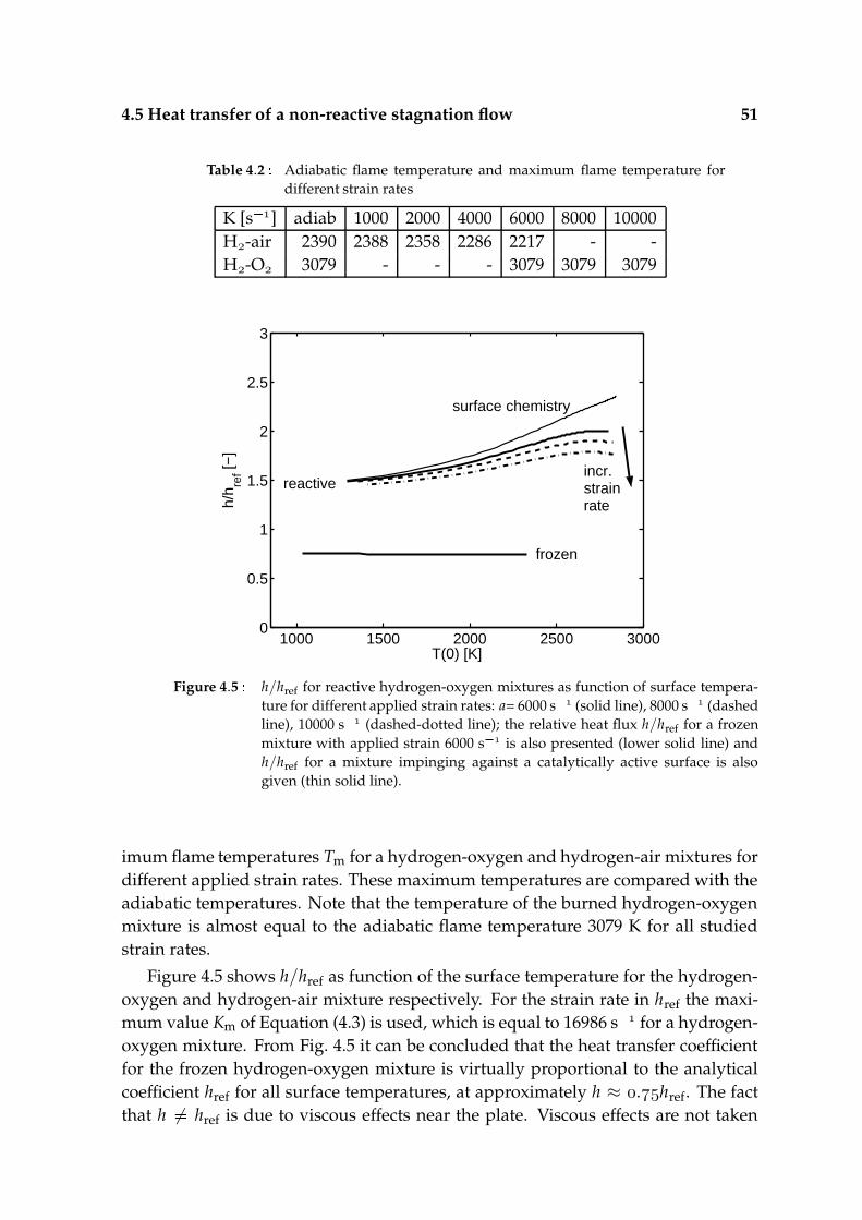
4.5 Heat transfer of a non-reactive stagnation flow 51
Table 4.2 Adiabatic flame temperature and maximum flame temperature fordifferent strain rates
K [s ] adiab 1000 2000 4000 6000 8000 10000H-air 2390 2388 2358 2286 2217 - -H-O 3079 - - - 3079 3079 3079
1000 1500 2000 2500 30000
0.5
1
1.5
2
2.5
3
reactive
frozen
surface chemistry
T(0) [K]
h/h re
f [−]
incr.strainrate
Figure 4.5 h/href for reactive hydrogen-oxygen mixtures as function of surface tempera-ture for different applied strain rates: a= 6000 s (solid line), 8000 s (dashedline), 10000 s (dashed-dotted line); the relative heat flux h/href for a frozenmixture with applied strain 6000 s is also presented (lower solid line) andh/href for a mixture impinging against a catalytically active surface is alsogiven (thin solid line).
imum flame temperatures Tm for a hydrogen-oxygen and hydrogen-air mixtures fordifferent applied strain rates. These maximum temperatures are compared with theadiabatic temperatures. Note that the temperature of the burned hydrogen-oxygenmixture is almost equal to the adiabatic flame temperature 3079 K for all studiedstrain rates.
Figure 4.5 shows h/href as function of the surface temperature for the hydrogen-oxygen and hydrogen-air mixture respectively. For the strain rate in href the maxi-mum value Km of Equation (4.3) is used, which is equal to 16986 s for a hydrogen-oxygen mixture. From Fig. 4.5 it can be concluded that the heat transfer coefficientfor the frozen hydrogen-oxygen mixture is virtually proportional to the analyticalcoefficient href for all surface temperatures, at approximately h ≈ .href. The factthat h 6 href is due to viscous effects near the plate. Viscous effects are not taken

52 Heat transfer mechanisms of laminar flames of hydrogen+oxygen
600 800 1000 1200 1400 1600 18000
0.5
1
1.5
reactive
frozen
T(0) [K]
h/h re
f [−]
incr. strainrate
Figure 4.6 h/href for reactive hydrogen-air mixtures as function of surface temperature fordifferent applied strain rates: a 2000 s (solid line), 4000 s (dashed line),6000 s (dashed-dotted line); the relative heat flux h/href for a frozen mixturewith applied strain 6000 s is also presented (lower dashed-dotted line).
into account in href. For zero viscosity, it appeared numerically that h ≈ href whichvalidates the analytical approximation, Equation (4.17).
The burned mixtures of the hydrogen-oxygen are approximately in chemicalequilibrium while the burned hydrogen-air mixture is not. The adiabatic temper-ature of a stoichiometric hydrogen-air flame is approximately 2390 K. However, theburned mixtures reach a lower temperature for all strain rates investigated here (seetable 4.2). It can be concluded that for these strain rates the burned hydrogen-airmixtures have not reached chemical equilibrium. Figure 4.6 shows h/href for thefrozen hydrogen-air mixture as function of the surface temperature as well. The ob-servations for the hydrogen-oxygen mixture also hold for the hydrogen-air mixture.Note that h ≈ .href now.
4.6 Heat transfer of a reactive stagnation flow
In the previous section the heat transfer from a chemically frozen mixture to a flatplate was discussed. Now we will discuss the importance of chemistry in the bound-ary layer and its effect on the heat transfer. The heat transfer of hydrogen-oxygenand hydrogen-air flames is considered for different strain rates.
First, the heat transfer from a burned but still chemically reactive hydrogen-oxygen and hydrogen-air mixture to a plate is studied. Both mixtures have an ap-plied strain rate of 6000 s . In Fig. 4.4 the heat transfer rates are plotted together
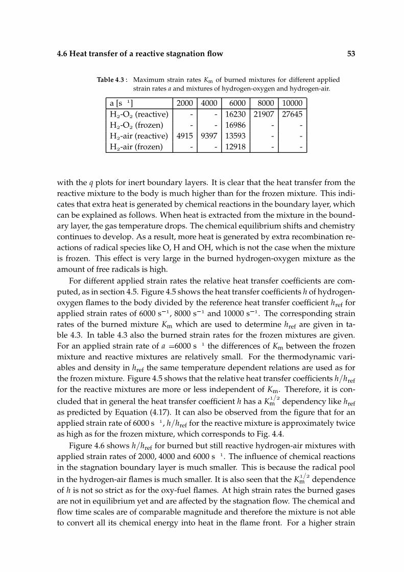
4.6 Heat transfer of a reactive stagnation flow 53
Table 4.3 Maximum strain rates Km of burned mixtures for different appliedstrain rates a and mixtures of hydrogen-oxygen and hydrogen-air.
a [s ] 2000 4000 6000 8000 10000H-O (reactive) - - 16230 21907 27645H-O (frozen) - - 16986 - -H-air (reactive) 4915 9397 13593 - -H-air (frozen) - - 12918 - -
with the q plots for inert boundary layers. It is clear that the heat transfer from thereactive mixture to the body is much higher than for the frozen mixture. This indi-cates that extra heat is generated by chemical reactions in the boundary layer, whichcan be explained as follows. When heat is extracted from the mixture in the bound-ary layer, the gas temperature drops. The chemical equilibrium shifts and chemistrycontinues to develop. As a result, more heat is generated by extra recombination re-actions of radical species like O, H and OH, which is not the case when the mixtureis frozen. This effect is very large in the burned hydrogen-oxygen mixture as theamount of free radicals is high.
For different applied strain rates the relative heat transfer coefficients are com-puted, as in section 4.5. Figure 4.5 shows the heat transfer coefficients h of hydrogen-oxygen flames to the body divided by the reference heat transfer coefficient href forapplied strain rates of 6000 s , 8000 s and 10000 s . The corresponding strainrates of the burned mixture Km which are used to determine href are given in ta-ble 4.3. In table 4.3 also the burned strain rates for the frozen mixtures are given.For an applied strain rate of a 6000 s the differences of Km between the frozenmixture and reactive mixtures are relatively small. For the thermodynamic vari-ables and density in href the same temperature dependent relations are used as forthe frozen mixture. Figure 4.5 shows that the relative heat transfer coefficients h/hreffor the reactive mixtures are more or less independent of Km. Therefore, it is con-cluded that in general the heat transfer coefficient h has a K/
m dependency like hrefas predicted by Equation (4.17). It can also be observed from the figure that for anapplied strain rate of 6000 s , h/href for the reactive mixture is approximately twiceas high as for the frozen mixture, which corresponds to Fig. 4.4.
Figure 4.6 shows h/href for burned but still reactive hydrogen-air mixtures withapplied strain rates of 2000, 4000 and 6000 s . The influence of chemical reactionsin the stagnation boundary layer is much smaller. This is because the radical poolin the hydrogen-air flames is much smaller. It is also seen that the K/
m dependenceof h is not so strict as for the oxy-fuel flames. At high strain rates the burned gasesare not in equilibrium yet and are affected by the stagnation flow. The chemical andflow time scales are of comparable magnitude and therefore the mixture is not ableto convert all its chemical energy into heat in the flame front. For a higher strain
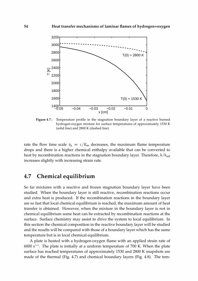
54 Heat transfer mechanisms of laminar flames of hydrogen+oxygen
−0.05 −0.04 −0.03 −0.02 −0.01 01400
1600
1800
2000
2200
2400
2600
2800
3000
3200
x [cm]
T [K
]
T(0) = 1530 K
T(0) = 2800 K
Figure 4.7 Temperature profile in the stagnation boundary layer of a reactive burnedhydrogen-oxygen mixture for surface temperatures of approximately 1530 K(solid line) and 2800 K (dashed line).
rate the flow time scale τb /Km decreases, the maximum flame temperaturedrops and there is a higher chemical enthalpy available that can be converted toheat by recombination reactions in the stagnation boundary layer. Therefore, h/hrefincreases slightly with increasing strain rate.
4.7 Chemical equilibrium
So far mixtures with a reactive and frozen stagnation boundary layer have beenstudied. When the boundary layer is still reactive, recombination reactions occurand extra heat is produced. If the recombination reactions in the boundary layerare so fast that local chemical equilibrium is reached, the maximum amount of heattransfer is obtained. However, when the mixture in the boundary layer is not inchemical equilibrium some heat can be extracted by recombination reactions at thesurface. Surface chemistry may assist to drive the system to local equilibrium. Inthis section the chemical composition in the reactive boundary layer will be studiedand the results will be compared with those of a boundary layer which has the sametemperature but is in local chemical equilibrium.
A plate is heated with a hydrogen-oxygen flame with an applied strain rate of6000 s . The plate is initially at a uniform temperature of 700 K. When the platesurface has reached temperatures of approximately 1530 and 2800 K snapshots aremade of the thermal (Fig. 4.7) and chemical boundary layers (Fig. 4.8). The tem-
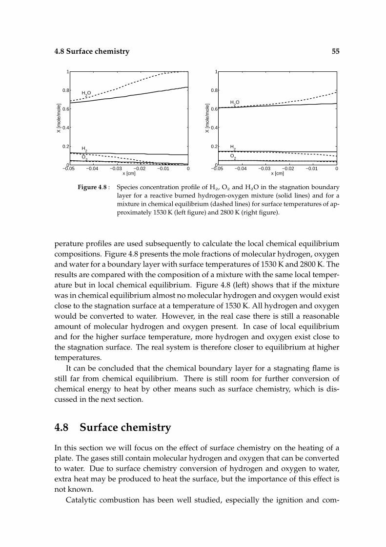
4.8 Surface chemistry 55
−0.05 −0.04 −0.03 −0.02 −0.01 00
0.2
0.4
0.6
0.8
1
O2
H2
H2O
x [cm]
X [m
ole/
mol
e]
−0.05 −0.04 −0.03 −0.02 −0.01 00
0.2
0.4
0.6
0.8
1
O2
H2
H2O
x [cm]
X [m
ole/
mol
e]
Figure 4.8 Species concentration profile of H, O and HO in the stagnation boundarylayer for a reactive burned hydrogen-oxygen mixture (solid lines) and for amixture in chemical equilibrium (dashed lines) for surface temperatures of ap-proximately 1530 K (left figure) and 2800 K (right figure).
perature profiles are used subsequently to calculate the local chemical equilibriumcompositions. Figure 4.8 presents the mole fractions of molecular hydrogen, oxygenand water for a boundary layer with surface temperatures of 1530 K and 2800 K. Theresults are compared with the composition of a mixture with the same local temper-ature but in local chemical equilibrium. Figure 4.8 (left) shows that if the mixturewas in chemical equilibrium almost no molecular hydrogen and oxygen would existclose to the stagnation surface at a temperature of 1530 K. All hydrogen and oxygenwould be converted to water. However, in the real case there is still a reasonableamount of molecular hydrogen and oxygen present. In case of local equilibriumand for the higher surface temperature, more hydrogen and oxygen exist close tothe stagnation surface. The real system is therefore closer to equilibrium at highertemperatures.
It can be concluded that the chemical boundary layer for a stagnating flame isstill far from chemical equilibrium. There is still room for further conversion ofchemical energy to heat by other means such as surface chemistry, which is dis-cussed in the next section.
4.8 Surface chemistry
In this section we will focus on the effect of surface chemistry on the heating of aplate. The gases still contain molecular hydrogen and oxygen that can be convertedto water. Due to surface chemistry conversion of hydrogen and oxygen to water,extra heat may be produced to heat the surface, but the importance of this effect isnot known.
Catalytic combustion has been well studied, especially the ignition and com-
56 Heat transfer mechanisms of laminar flames of hydrogen+oxygen
bustion of pure hydrogen-oxygen mixtures over platinum surfaces at low pres-sures [51], [112]. Also the interaction between homogeneous and heterogeneouschemistry for hydrogen mixtures in stagnation flows on platinum layers at elevatedtemperatures was studied numerically [59], [134] and experimentally [60]. Transientignition of premixed stagnation-point flows over a catalytic surface was investigatednumerically in [120]. Also work has been done on the modeling of heterogeneouscatalytic combustion in stagnation-point flows recently [92]. Mokhov et al. [97] re-port from experimental investigations and numerical simulations the behavior ofCO and OH in the laminar boundary layer of a combusted propane-air stagnationflow. Hereby the plate temperature, equivalence ratio of the oncoming flow andcatalytic properties of the surface is varied.
Because the main interest goes to the contribution of surface chemistry to theheat transfer and a kinetic mechanism for quartz does not exist, it is assumed thatthe surface acts in a similar way to platinum. By using platinum as a catalyst themaximum contribution to the heat flux can be determined. For the chemical kineticmodel, the model of Hellsing et al. [51] is used. The model of Hellsing et al. hasbeen validated extensively for low pressures and moderate temperatures. Althoughwe do not have a low overall pressure the partial pressures of hydrogen and oxygenare comparable to the partial pressures for hydrogen and oxygen in Hellsing et al.The model was extrapolated to high temperatures. Conversion of a reactant to aproduct by surface reactions has different steps. These steps are absorption, with orwithout dissociation, diffusion, surface reactions and desorption. The typical timescale for surface chemistry corresponds to the time scale of the slowest step. If thesurface has to remain catalytically active, the slowest step has to be the adsorptionstep, otherwise the surface will be fully covered and no significant surface reactionswill take place anymore. Therefore let us consider the absorption rate of a reactantin the gas phase. The absorption rate of species i is ri Si
θ, T Fi
pi, mi, T where Fi
is the impingement rate of species i and Si the sticking coefficient [51]. The stickingcoefficient may be dependent on the surface coverage θ and temperature T. Theimpingement rate is the rate of molecules that hit a surface site [116],
Fi pi AsiteπmikBT /
. (4.18)
The absorption rate is the number of molecules that is absorbed by a single surfacesite per unit time. Thus the typical time scale of absorption is τsi /ri. For hy-drogen and oxygen absorption on a platinum surface with the conditions discussedpreviously the time scales are of the order 10 -10 s. In general the absorption ofoxygen takes longer than the absorption of hydrogen here, due to a lower partialpressure and sticking coefficient and a higher specific mass of oxygen. Since theabsorption time scales are much faster than the typical time scales discussed in sec-tion 4.3, it can be assumed safely that the surface chemistry follows the gas phaseprocesses quasi-steadily.

4.8 Surface chemistry 57
−0.05 −0.04 −0.03 −0.02 −0.01 00.02
0.04
0.06
0.08
0.1
0.12
0.14
0.16
O2
H2
x [cm]
X [m
ole/
mol
e]
−0.05 −0.04 −0.03 −0.02 −0.01 02750
2800
2850
2900
2950
3000
3050
x [cm]
T [K
]
without surface chemistry
with surface chemistry
Figure 4.9 Species concentration profile of H and O (left figure) and temperature profile(right figure) of the stagnation boundary layer for a reactive burned hydrogen-oxygen mixture with (dashed line) and without (solid line) surface chemistryfor a surface temperature of 2800 K.
A stoichiometric hydrogen-oxygen flame with applied strain rate of 6000 s
is studied. Figure 4.9 (left) shows the species composition of molecular hydrogenand oxygen in the stagnation boundary layer of a hydrogen-oxygen flame, wherein one case (solid line) no surface chemistry is taken into account and in the othercase (dashed line) surface chemistry is included. The surface temperature is 2800K. Near the surface the concentration of hydrogen and oxygen are somewhat lowerfor the situation where surface chemistry is included than for the situation where nosurface chemistry is included. From this we may conclude that more hydrogen andoxygen is converted to water with a reactive surface and extra heat is produced.
Figure 4.9 (right) shows the temperature profiles in the stagnation boundarylayer for a surface temperature of 2800 K. When no surface chemistry is taken intoaccount, the temperature profile shown is reached after 10 s in case of a quartz plateof 5 mm thickness. When surface chemistry is taken into account the profile shownis reached after 8.1 s. This means that surface chemistry reduces the heat up timeconsiderably in spite of the small differences in species profiles.
Figure 4.4 and 4.5 present the heat flux and heat transfer coefficient as functionof surface temperature for both cases with and without surface chemistry. For highsurface temperatures the heat transfer coefficient for a catalytically active surface ishigher than for a non-catalytically active surface.
With the chemical kinetic model studied here, it can be concluded that surfacechemistry influences the heat transfer rate significantly. Especially at high tempera-tures the effect of surface chemistry is significant.

58 Heat transfer mechanisms of laminar flames of hydrogen+oxygen
4.9 Conclusions
In this paper the heat transfer of laminar hydrogen-oxygen flames to a stagnationplane has been studied both analytically and numerically. The influence of strainrate, gas phase chemistry, and surface chemistry has been taken into account. It isshown that the strain rate is the dominating parameter for the heating process, butthe other two effects are substantial. All studied (stoichiometric) hydrogen-oxygenflames have an adiabatic burning temperature of 3079 K. A comparison has alsobeen made with hydrogen-air flames. These have an adiabatic flame temperatureof 2390 K at low strain rates (below 2000 s ). For higher strain rates the maximumflame temperature decreases, due to the fact that the flame cools down before a fullconversion to the final reaction products has taken place.
Different time scales have been identified. The time scale of the flame chemistryis of the order of 10 s, the time scale of the boundary layer of the stagnation flowis of the order of 10 s. The heating time scale of the plate depends on the platethickness. For a quartz plate with a thickness of the order of millimeters, the timescale is of the order of 1-10 s. The time scale increases with thickness. The heat fluxis therefore not dependent on the temperature profile in the plate. The heat fluxfrom the stagnation flow to the plate then only depends on the stagnation flow andplate surface temperature. A relation for the convective heat transfer coefficient isintroduced.
First the heat transfer of a burned but chemically frozen mixture stagnating tothe plate was studied. The numerically determined heat transfer coefficient for thefrozen hydrogen-oxygen mixture is almost proportional to the analytical coefficient.Due to the viscous sublayer, a constant factor of 0.75 difference between the analyt-ically and the numerically determined heat transfer coefficient is observed. For theburned and frozen hydrogen-air mixture this relation also holds, but this factor nowreduces to 0.6.
Second, a numerical study is performed on the heat transfer of a burned and stillchemically active mixture stagnating to the plate. For a burned hydrogen-oxygenmixture the heat transfer coefficient shows a clear square root dependency on thestrain rate, as predicted using the analytical model. If the burned mixture has notreached chemical equilibrium the square root dependency is not strictly adhered toanymore. When the boundary layer is chemically active the heat transfer coefficientis approximately twice as high as for the frozen mixture. This is in contrast to ahydrogen-air mixture, where the difference between a chemically active and frozenmixture is not so large due to the smaller amount of free radicals in the reactive flow.
Finally, it is shown that the chemical boundary layer of a stagnation flame is farfrom chemical equilibrium. Surface chemistry is one of the means to convert someof the remaining chemical energy to heat. By assuming a surface chemistry modelfor platinum, it is shown that surface chemistry can influence the heat transfer sig-nificantly, especially at high temperatures.
Chapter5Thermochemical heat releaseof laminar stagnation flamesof fuel and oxygen
Abstract
Heat transfer is a complex phenomenon that can involve conduction, convection, ra-diation, condensation, and boiling. In the case of heat transfer by flames producedby pure oxygen or oxygen enriched air combustion, a mechanism called thermo-chemical heat release (TCHR) can be responsible for up to half of the total heattransfer rate. In these very hot flames chemical equilibrium is reached before fullconversion into products is achieved. TCHR is the result of recombination reactionsin the thermal boundary layer. In this paper a method is described to model TCHRin a one-dimensional stagnation flame, which can be applied to fuels of an almostarbitrarily complex composition. In this method the flame chemistry is decoupledfrom the chemistry in the thermal stagnation boundary layer. An equilibrium calcu-lation is used to determine the chemical composition after the flame. This mixtureis then used as input for the boundary layer calculation, for which a skeletal CH
mechanism suffices. It is shown under which conditions this method can be applied,the effect of strain rate is studied, and the method is demonstrated by calculating theTCHR for a number of different fuels.
This chapter has been submitted as: M.F.G. Cremers, M.J. Remie, K.R.A.M. Schreel, L.P.H.de Goey, Thermochemical heat release of laminar stagnation flames of fuel and oxygen, Proc.Comb. Inst. (2006)
60 Thermochemical heat release of laminar stagnation flames of fuel+oxygen
5.1 Introduction
Heating of products with impinging jets has been studied extensively in the past.High stagnation point heat fluxes can be obtained both in the turbulent and the lam-inar case. Although mainly of industrial interest (see e.g. Baukal [7]), even subjectslike aerospace vehicles reentering the atmosphere [47] can be described as imping-ing jets. A particular class of jets is the one when flames are the origin. Literaturereviews are given by e.g. Van der Meer [93], Stutzenberger [125], Baukal and Geb-hart [5] and recently Viskanta [131].
When high heat transfer rates are needed, it is advantageous to use oxygen en-riched air or even pure oxygen as the oxidizer [114, 34]. The high flame temperaturescombined with the high jet velocities enabled by the high burning velocities resultin heat transfer rates easily exceeding MW/m, and can be applied very locally.Applications can be found in, among others, the steel industry [43, 87] and glassindustry [133].
The heat transfer of a flame jet to an object is a complex combination of severalphysical and chemical processes. Baukal [7] distinguishes six mechanisms: convec-tion, conduction, radiation, thermochemical heat release, water vapor condensation,and boiling. Their relative importance depends on the geometry of the stagnationtarget, burner/flame geometry, position of the burner, chemical composition, ther-modynamic properties, and inlet conditions. Also depending on these conditionsis whether the flow is laminar or turbulent, and different combustion modes ofimpinging jet flames can be defined [142]. For the special case of small, laminaroxygen+fuel flames, two mechanisms are dominant, viz. convection and, especially,thermochemical heat release (TCHR). When TCHR does not play a role, the maindriving mechanism for the heat transfer is the sensible enthalpy or temperature dif-ference between the hot gases and the surface. Semi-analytical heat transfer solu-tions in stagnation flows including forced convection have been developed by e.g.Sibulkin [121]. Recently, Remie et al. [110] derived an analytical solution for thestagnation boundary layer of hot gases impinging against a cold wall. TCHR can,however, be responsible for an enhancement of the convective heat transfer rate forapproximately a factor of for a H-O-flame [27].
TCHR occurs when the flame temperature is limited by chemical equilibriumand no full conversion of the fuel+oxidizer into water and/or carbondioxyde cantake place. The available heat of combustion is that high, that the equilibrium tem-perature for the intermediate chemical reactions is reached before a full (exothermic)chemical conversion into the final products can take place. For fuels based on carbonand hydrogen the highest temperature that can be reached is usually in the range of– K, depending on fuel and stoichiometry details. The flame contains thena high concentration of intermediate species (radicals). When this gas impinges on arelatively cold surface, the gaseous species cool down and exothermally recombineinto the stable products, releasing extra energy and boosting the heat transfer. Two
5.1 Introduction 61
different TCHR-mechanisms exist [47] known as equilibrium and catalytic TCHR. Inequilibrium TCHR, the recombination reactions occur in the boundary layer, whichis an important mechanism in oxy-fuel flames [4, 73, 27]. In catalytic TCHR the re-combination reactions occur at the target surface, and heterogenous reactions mayaccelerate this process. A mixture of these two mechanisms, mixed TCHR, was pro-posed by Nawaz [100].
TCHR is often quantified by taking the total enthalpy (the sensible plus thechemical enthalpy) as the driving force behind the heat transfer. Semi-analyticalsolutions, mostly at the stagnation point, including equilibrium TCHR and catalyticTCHR have been constructed by e.g. Fay and Riddell [44], Rosner [113], and Conollyand Davies [23]. A numerical study for hydrogen+oxygen combustion was recentlyperformed by Cremers [27] for both equilibrium and mixed TCHR. The additionaleffect of the catalytic TCHR could be quantified as a boost of % in the case ofa platinum surface. Another outcome of this study was that the dissociation andrecombination reactions affect not only the species concentrations, but also the tem-perature distribution in the stagnation boundary layer. Therefore, TCHR can not beconsidered separately from convection, as has also been noted by Viskanta [130].
In this paper a study is presented of the numerical computation of the TCHRfor a range of fuels with complex chemistry. Furthermore, the interaction betweenconvection (in the form of strain rate) and TCHR is studied. Detailed chemistrycalculations are computationally expensive and it is advantageous to use a one-dimensional geometry. Although this simplification is already reasonable for study-ing TCHR, it is also of practical relevance since a lot of heating configurations in-volve flame-object distances that are much smaller than the typical jet diameter. Butnonetheless, to accurately model a higher hydrocarbon flame involves usually veryelaborate chemical mechanisms, and a more practical approach is sought for. Todetermine the effect of TCHR, the stagnation boundary layer computations can betreated separately when the gas is in chemical equilibrium once it enters the stagna-tion boundary layer. As a mixture in chemical equilibrium only consists of relativelysmall species, a simple kinetic reaction mechanism can be used. The proposed strat-egy is to determine the chemical composition of the flame by means of an equilib-rium computation. The two underlying assumptions are (1) that the chemical equi-librium composition only consists of species that are present in the limited mech-anism (like for methane) and (2) chemical equilibrium is indeed reached after theflame front before the chemistry is affected by the stagnation boundary layer. Bothassumptions are checked and for the second assumption a criterium in the form ofa simple analytical equation is derived and assessed for its validity.
In the following section the general equations and computational domain areintroduced. Following, a spatial analysis of a stagnation flame is given. In the fourthsection the results with respect to TCHR are presented for different fuels and strainrates. The paper ends with conclusions.
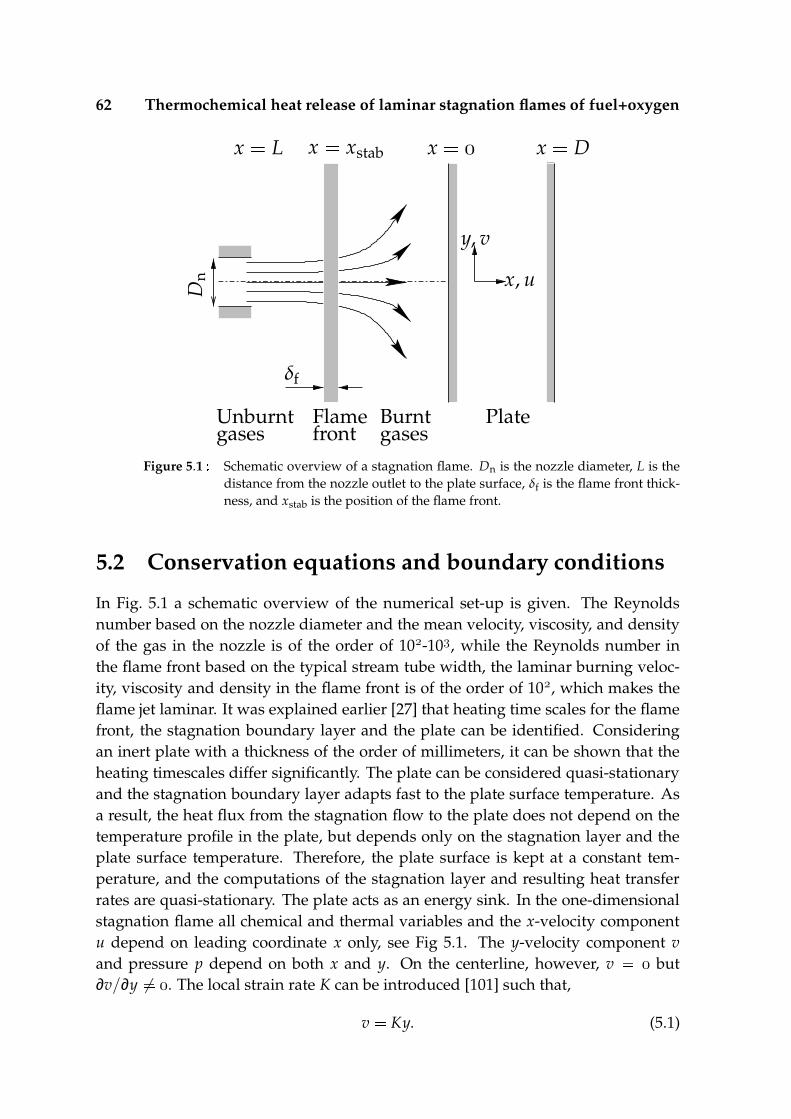
62 Thermochemical heat release of laminar stagnation flames of fuel+oxygen
x, u
y, v
Flamefront
Burntgases
Unburntgases
x
x Dx L
Plate
δf
x xstab
Dn
Figure 5.1 Schematic overview of a stagnation flame. Dn is the nozzle diameter, L is thedistance from the nozzle outlet to the plate surface, δf is the flame front thick-ness, and xstab is the position of the flame front.
5.2 Conservation equations and boundary conditions
In Fig. 5.1 a schematic overview of the numerical set-up is given. The Reynoldsnumber based on the nozzle diameter and the mean velocity, viscosity, and densityof the gas in the nozzle is of the order of 10-10, while the Reynolds number inthe flame front based on the typical stream tube width, the laminar burning veloc-ity, viscosity and density in the flame front is of the order of 10, which makes theflame jet laminar. It was explained earlier [27] that heating time scales for the flamefront, the stagnation boundary layer and the plate can be identified. Consideringan inert plate with a thickness of the order of millimeters, it can be shown that theheating timescales differ significantly. The plate can be considered quasi-stationaryand the stagnation boundary layer adapts fast to the plate surface temperature. Asa result, the heat flux from the stagnation flow to the plate does not depend on thetemperature profile in the plate, but depends only on the stagnation layer and theplate surface temperature. Therefore, the plate surface is kept at a constant tem-perature, and the computations of the stagnation layer and resulting heat transferrates are quasi-stationary. The plate acts as an energy sink. In the one-dimensionalstagnation flame all chemical and thermal variables and the x-velocity componentu depend on leading coordinate x only, see Fig 5.1. The y-velocity component vand pressure p depend on both x and y. On the centerline, however, v but∂v/∂y 6 . The local strain rate K can be introduced [101] such that,
v Ky. (5.1)

5.2 Conservation equations and boundary conditions 63
The conservation of mass is then expressed by the continuity equation [136],
∂ρ
∂t ∂ρu
∂x ρK, (5.2)
with ρ the density and t time. In the one-dimensional stagnation flame the y-momentum equation reduces to an effective equation for the strain rate (see e.g. [101]and [126]):
ρ∂K∂t
ρu
∂K∂x ∂
∂x
(
µ∂K∂x
)
jG
ρua ρK , (5.3)
where ρu equals the density and K a the strain rate of the unburned mixture atthe inflow boundary (x L). a is also known as the applied strain rate and µ isthe viscosity. The geometrical parameter jG for a planar and jG for anaxisymmetric flow. In this paper, a planar flow will be considered. In a chemicallyreacting flow, a conservation equation for every species i has to be solved in termsof mass fractions Yi,
∂ρYi
∂t ∂ρuYi
∂x ∂
∂x
(
ρDim∂Yi
∂x
)
ρi ρKYi , (5.4)
with Dim the effective diffusion coefficient, which is calculated using a mixture aver-aged diffusion model [53], [41]. Furthermore, the chemical source term is quantifiedby ρi Mi
k νikωk where Mi is the molar mass of species i, νik the stoichiometric
coefficient of species i in reaction k, and ωk the reaction rate of reaction k. The en-ergy conservation equation for the gas is written in terms of the specific enthalpy jand temperature T,
∂ρ j∂t
∂ρuj∂x
∂∂x
(
λ∂T∂x
)
∂∂x
( N
i
jiρDim∂Yi
∂x
)
ρK j, (5.5)
with λ the theraml conductivity coefficient. The specific enthalpy of the mixture is amass-weighted sum of the specific enthalpies of all species
ji ji T
T
cp,iT∗ dT∗, (5.6)
ji being the chemical formation enthalpy of species i at reference temperature T
and cp,i the specific heat capacity of species i. The set of equations for the gas isclosed by the ideal gas-law,
ρ pMRT
(5.7)
with R the universal gas constant and M the average molar mass of the mixture. Forlow Mach number flows, the pressure in this last expression can be taken constantp pu, with pu the atmospheric pressure at the inlet.
At the inlet x L, Dirichlet boundary conditions are applied: K a, Yi Yi,uand T Tu. The mass flux at the inlet is determined from the strain rate and density

64 Thermochemical heat release of laminar stagnation flames of fuel+oxygen
−0.5 −0.4 −0.3 −0.2 −0.1 0 0.1
0
0.2
0.4
0.6
0.8
1
1.2
x [cm]
T/Tmax
K/Kmax
YCO
/YmaxCO
H δf
δe
δth
Figure 5.2 Non-dimensional temperature, strain rate, and CO mass fractions in a CH-O-stagnation flame with applied strain rate a s and T K.
profile. At the stagnation plane (x )it is assumed that there is no species or masstransport from the gas to the solid, i.e. ∂Yi/∂x and u . Furthermore the platetemperature is set at a constant value T T and the no-slip boundary condition isapplied, which implies that K .
5.3 Spatial analysis of the stagnation flame
A flame impinging against a surface can be divided in three zones: a flame frontwith thickness δf, an equilibrium zone with width δe and a thermal stagnationboundary layer with thickness δth. The spatial classification of the different zonesis shown in Fig. 5.2 together with the temperature, strain rate and species profilewhich are discussed later. An unburned mixture enters the computational domainat x L, see Fig. 5.1, and at approximately x H, where the u-velocity compo-nent equals the laminar burning velocity sL, the flame stabilises, and a flame frontis formed. At the end of the flame front, at x H
δf, the burned mixture is inthermal and chemical equilibrium, and the equilibrium mixture enters the thermalstagnation boundary layer at x δth. The distance from the stabilisation posi-tion to the plate surface H is dependent on the flow conditions, while the flamefront thickness is mainly governed by chemistry and thermodynamics. The thermalboundary layer thickness depends on the thermodynamic and flow conditions. Theequilibrium zone ’fills the gap’ between the flame front and the stagnation zone.

5.3 Spatial analysis of the stagnation flame 65
−0.6 −0.4 −0.2 0
0
0.2
0.4
0.6
0.8
1
x [cm]
u/u0
K/Km
H δvisc
Figure 5.3 Non-dimensional velocity u/u and strain rate K/Km profiles for a theoreticalflow calculated with Eq. (5.8) and (5.9) respectively (solid lines) (with K atx H ' . cm), and for a stagnation flame computed with the full set ofequations (dashed lines), Km . · s .
The presence of an equilibrium zone indicates that the flame front and stagnationboundary layer can be decoupled. However, it will be shown that with increasingstrain rate, the equilibrium zone width decreases, and for a certain critical strainrate the equilibrium zone will vanish. The flame is then so close to the surface thatit feels the surface before it has fully developed, and chemical equilibrium is notreached. In that case, the flame front and the stagnation zone can not be decoupled.In the next subsections, an analysis is performed for the different zones. In the firstsubsection the position and width of the flame front is estimated. The second sub-section discusses the thermal stagnation boundary layer. In the third subsection, thewidth of the equilibrium zone is determined, and a criterium is given for the criticalstrain rate.
5.3.1 Flame front
In Remie et al. [110], an analysis was given to compute the heat flux from a hotnon-reactive gas impinging against a flat plate. The spatial domain of the gas wasdivided in a region far from the plate, H < x < δvisc in Fig. 5.3, where vis-cous effects do not play a role, and a region near the plate, δvisc < x < , whereviscosity affects the flow field and creates a stagnation boundary layer. For bothregions, velocity profiles and strain profiles are determined and the two regions are
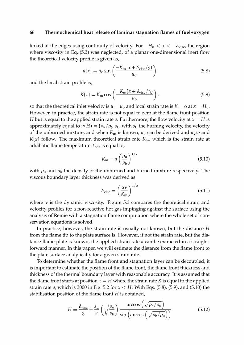
66 Thermochemical heat release of laminar stagnation flames of fuel+oxygen
linked at the edges using continuity of velocity. For H < x < δvisc, the regionwhere viscosity in Eq. (5.3) was neglected, of a planar one-dimensional inert flowthe theoretical velocity profile is given as,
ux u sin
( Kmx
δvisc/ u
)
(5.8)
and the local strain profile is,
Kx Km cos
( Kmx
δvisc/ u
)
. (5.9)
so that the theoretical inlet velocity is u u and local strain rate is K at x H.However, in practice, the strain rate is not equal to zero at the flame front positionH but is equal to the applied strain rate a. Furthermore, the flow velocity at x H isapproximately equal to u
H ρu/ρb sL, with sL the burning velocity, the velocity
of the unburned mixture, and when Km is known, u can be derived and ux and
Kx follow. The maximum theoretical strain rate Km, which is the strain rate at
adiabatic flame temperature Tad, is equal to,
Km a(
ρu
ρb
)/
(5.10)
with ρu and ρb the density of the unburned and burned mixture respectively. Theviscous boundary layer thickness was derived as
δvisc (
ν
Km
)/
(5.11)
where ν is the dynamic viscosity. Figure 5.3 compares the theoretical strain andvelocity profiles for a non-reactive hot gas impinging against the surface using theanalysis of Remie with a stagnation flame computation where the whole set of con-servation equations is solved.
In practice, however, the strain rate is usually not known, but the distance Hfrom the flame tip to the plate surface is. However, if not the strain rate, but the dis-tance flame-plate is known, the applied strain rate a can be extracted in a straight-forward manner. In this paper, we will estimate the distance from the flame front tothe plate surface analytically for a given strain rate.
To determine whether the flame front and stagnation layer can be decoupled, itis important to estimate the position of the flame front, the flame front thickness andthickness of the thermal boundary layer with reasonable accuracy. It is assumed thatthe flame front starts at position x H where the strain rate K is equal to the appliedstrain rate a, which is 3000 in Fig. 5.2 for x < H. With Eqs. (5.8), (5.9), and (5.10) thestabilisation position of the flame front H is obtained,
H δvisc
sL
a
(√
ρu
ρb
) arccos(
√
ρb/ρu
)
sin(
arccos(
√
ρb/ρu
)) (5.12)
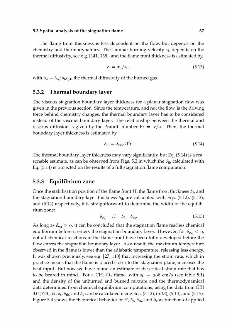
5.3 Spatial analysis of the stagnation flame 67
The flame front thickness is less dependent on the flow, but depends on thechemistry and thermodynamics. The laminar burning velocity sL depends on thethermal diffusivity, see e.g. [141, 135], and the flame front thickness is estimated by,
δf αb/sL, (5.13)
with αb λb/ρbcpb the thermal diffusivity of the burned gas.
5.3.2 Thermal boundary layer
The viscous stagnation boundary layer thickness for a planar stagnation flow wasgiven in the previous section. Since the temperature, and not the flow, is the drivingforce behind chemistry changes, the thermal boundary layer has to be consideredinstead of the viscous boundary layer. The relationship between the thermal andviscous diffusion is given by the Prandtl number Pr ν/α. Then, the thermalboundary layer thickness is estimated by,
δth δvisc/Pr. (5.14)
The thermal boundary layer thickness may vary significantly, but Eq. (5.14) is a rea-sonable estimate, as can be observed from Figs. 5.2 in which the δth calculated withEq. (5.14) is projected on the results of a full stagnation flame computation.
5.3.3 Equilibrium zone
Once the stabilisation position of the flame front H, the flame front thickness δf, andthe stagnation boundary layer thickness δth are calculated with Eqs. (5.12), (5.13),and (5.14) respectively, it is straightforward to determine the width of the equilib-rium zone:
δeq H δf δth. (5.15)
As long as δeq > , it can be concluded that the stagnation flame reaches chemicalequilibrium before it enters the stagnation boundary layer. However, for δeq < ,not all chemical reactions in the flame front have been fully developed before theflow enters the stagnation boundary layer. As a result, the maximum temperatureobserved in the flame is lower than the adiabatic temperature, releasing less energy.It was shown previously, see e.g. [27, 110] that increasing the strain rate, which inpractice means that the flame is placed closer to the stagnation plane, increases theheat input. But now we have found an estimate of the critical strain rate that hasto be beared in mind. For a CH-O flame, with sL cm/s (see table 5.1)and the density of the unburned and burned mixture and the thermodynamicaldata determined from chemical equilibrium computations, using the data from GRI3.0 [123], H, δf, δth, and δe can be calculated using Eqs. (5.12), (5.13), (5.14), and (5.15).Figure 5.4 shows the theoretical behavior of H, δf, δth, and δe as function of applied
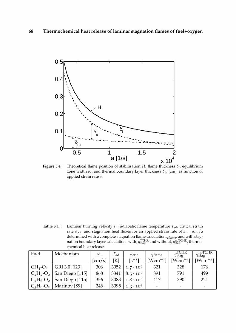
68 Thermochemical heat release of laminar stagnation flames of fuel+oxygen
0.5 1 1.5 2x 10
4
0
0.1
0.2
0.3
0.4
0.5
a [1/s]
H
δf δ
e
δth
Figure 5.4 Theoretical flame position of stabilisation H, flame thickness δf, equilibriumzone width δe, and thermal boundary layer thickness δth [cm], as function ofapplied strain rate a.
Table 5.1 Laminar burning velocity sL, adiabatic flame temperature Tad, critical strainrate acrit, and stagnation heat fluxes for an applied strain rate of a acrit/determined with a complete stagnation flame calculation qflame, and with stag-nation boundary layer calculations with, qTCHR
stag and without, qnoTCHRstag , thermo-
chemical heat release.
Fuel Mechanism sL Tad acrit qflame qTCHRstag qnoTCHR
stag[cm/s] [K] [s ] [Wcm ] [Wcm ] [Wcm ]
CH-O GRI 3.0 [123] 306 3052 . · 321 328 176CH-O San Diego [115] 868 3341 . · 891 791 499CH-O San Diego [115] 356 3083 . · 417 390 221CH-O Marinov [89] 246 3095 . · - - -

5.4 Chemistry in the stagnation boundary layer 69
−0.08 −0.06 −0.04 −0.02 0
0
0.2
0.4
0.6
0.8
1
1.2
x [cm]
T/Tmax
K/Kmax
YCO
/YmaxCO
δf
δth
H
Figure 5.5 Non-dimensional temperature, strain rate, and CO mass fractions in a stagna-tion flame for applied strain rate a s .
strain rate. The figure shows that the critical applied strain rate is approximatelyacrit . · s . Furthermore, Figs 5.2 and 5.5 show that for an applied strainrate of a s the burned gases reach chemical equilibrium indicated by theflat part in the CO-profile and the maximum temperature Tmax K, whichis close to the adiabatic temperature of 3054 K, while for an applied strain rate ofa s the flat part in the CO-profile is not observed and the maximumtemperature Tmax K, is well below adiabatic temperature. This justifies thetheoretical approach.
5.4 Chemistry in the stagnation boundary layer
For computing a stagnation flame including the flame front, a complex kinetic mech-anism is needed when higher alkanes are used as fuel. If the applied strain rate isbelow the critical strain rate, the stagnation layer calculations can be treated sepa-rately from the flame calculations. The stagnation layer structure is then calculatedwith a compact chemical kinetic mechanism, using the equilibrium mixture as inletcondition. This is only allowed if the mixture is in chemical equilibrium once it en-ters the stagnation boundary layer, and when all major species in the equilibriummixture are present in the compact mechanism. Then, the effect of TCHR in thestagnation boundary layer on the total heat transfer can be determined easily.
Equilibrium calculations are performed for various hydrocarbon-O mixturesand table 5.1 shows the equilibrium temperatures of those mixtures. The equilib-

70 Thermochemical heat release of laminar stagnation flames of fuel+oxygen
0.5 1 1.5 2x 10
4
0
100
200
300
400
500
a [1/s]
q [W
/cm
2 ]
a < acrit
a > acrit
Figure 5.6 Heat transfer rate q as function of applied strain rate a for a CH-O stagnationflame (dashed-dotted line) and an equilibrium mixture with (solid line) andwithout (dashed line) TCHR.
rium temperature and composition of the CH-O-mixture are determined withthe thermodynamical data from the GRI 3.0 [123] data set, which consists of 53species. The equilibrium temperature and composition of the CH-O and CH-O-mixtures are determined with the thermodynamical data from the San Diegodata set [115], which consists of 44 species, and those of the CH-O-mixture aredetermined with the extensive n-butane data set of Marinov et al. [89], which con-sists of 155 species. However, on the roadpath towards chemical equilibrium ofall mixtures, the bigger molecules break down to smaller species. These smallerspecies are also present in more compact chemical schemes like the CH skeletonchemical kinetic scheme of Smooke [124], which only consists of 16 species. It canbe shown that all species that are not present in the Smooke mechanism have verylow concentrations, with mole fractions less that 10 , in the equilibrium mixturesfor all abovementioned oxy-fuel mixtures. As a result, this compact chemical kineticscheme can be used for the stagnation boundary layer computations, as long as theflame reaches chemical equilibrium before it enters the stagnation boundary layer.
The composition and adiabatic temperature of the equilibrium mixture serve,together with the laminar burning velocity, determined from flame calculations orliterarature, and the local strain rate K, derived from Eq. (5.9) as inlet boundaryconditions for the stagnation boundary layer. Laminar burning velocities are givenin table 5.1. From stagnation layer computations with and without TCHR the heatfluxes to the stagnation plane are determined and compared with the heat fluxesobtained from complete stagnation flame computations. The heat fluxes for a CH-
5.4 Chemistry in the stagnation boundary layer 71
O-mixture are shown in Fig. 5.6 as function of applied strain rate a. For strainrates well below the critical strain rate, the heat fluxes calculated with the stagnationmixture with TCHR correspond well with the fluxes derived from full stagnationflame calculations. However, close to and especially above the critical strain rate,the heat fluxes start to deviate and the stagnation boudary layer computation withthermal and chemical equilibrium as inlet conditions overestimates the heat flux.Full flame calculations are needed to obtain accurate results. Due to TCHR speciesrecombine exothermally, boosting the heat transfer. It was shown previously, [27]that for an H-O mixture TCHR can boost the heat transfer up to a factor of 2.Figure 5.6 shows that for a completely burned CH-O mixture at low strain rates,this factor is also approximately equal to 2.
With Eq. (5.15) the critical strain rate acrit has been determined for different mix-tures, and the values are given in Table 5.1. With increasing laminar burning velocitysL and adiabatic temperature Tad the critical strain rate increases significantly. Forincreasing critical strain rate, the critical distance from the flame tip to the plate de-creases, which suggests that fast stagnation flames can be positioned closer to anobject. Then, a small change in the distance from flame tip to stagnation plane leadsto large variations of the strain rate. Determining the critical strain rate is there-fore more difficult for relatively fast flames, like CH-O-flames, than for relativelyslow flames, like CH-O-flames.
In Table 5.1 the stagnation heat fluxes for a complete stagnation flame qflamecalculated with the GRI 3.0 mechanism for the CH-O-flame and with the SanDiego mechanism for the CH-O and CH-O-flames are tabulated. Beside thesefluxes, also the heat fluxes determined with stagnation layer computations with andwithout TCHR, calculated with the compact mechanism of Smooke are given. Theflame and stagnation layer compuations are performed for an applied strain rateof a acrit/. For the CH-O and CH-O-flames, the heat fluxes determinedfrom complete flame calculations correspond well with the heat fluxes determinedfrom the stagnation layer calculations with TCHR. However, for the relatively fastand hot CH-O-flame, the difference is somewhat larger. It can be shown that fora CH-O-flame with applied strain rate a acrit/ the flow is not able to reachchemical equilibrium before it enters the stagnation boundary layer. Since a CH-O-flame reaches temperatures above the equilibrium temperature before it reachesequilibrium, the inlet temperature of the stagnation layer computations, for whichthe equilibrium temperature is taken, is underpredicted. As a result the correspond-ing heat transfer rate is also underpredicted.
Table 5.1 shows the heat fluxes determined from stagnation boundary layer com-putations with and without TCHR, but with equal inlet conditions. It shows that forCH-O, CH-O, and CH-O mixtures, TCHR enhances the total heat flux by afactor in the range of 1.5–2.
72 Thermochemical heat release of laminar stagnation flames of fuel+oxygen
5.5 Conclusions
In this paper the heat transfer of stagnating oxy-fuel flames to a target surface hasbeen studied numerically, for a set of hydrocarbon-oxygen mixtures. The effect ofthermochemical heat release (TCHR) on the total heat transfer was determined forincreasing applied strain rate, or equivalently decreasing distance from the flamefront to the target surface.
It was shown that for low strain rates, the burned mixture reaches chemical equi-librium once it leaves the flame front, but before it enters the stagnation boundarylayer. For increasing strain rate, the flame front and stagnation boundary layer startto interact, and chemical equilibrium is not reached anymore. Using the theoreticalanalysis of Remie et al. [110] a criterium for this critical strain was found.
As a result, for low strain rates, the flame front and stagnation boundary layercan be decoupled and the stagnation layer computations can be performed, usingan equilibrium mixture as inlet composition. It was shown, that these equilibriummixtures consist of relatively small species, such that a compact chemical kineticscheme can be used for the stagnation boundary layer computations, as long aschemical equilibrium is reached.
Furthermore, it was shown that for strain rates well below the critical strain rate,the heat fluxes to the target derived from the stagnation layer computations corre-spond well with the heat fluxes derived from complete flame computations. Onlyfor the relatively hot and fast CH-O-flame heat flux derived from the stagna-tion layer computations is somewhat underpredicted due to the overprediction ofthe critical strain rate. Furthermore, it was shown that stagnation boundary layerTCHR can boost the heat transfer rate with up to a factor of 1.5-2 for CH-O, CH-O, and CH-O flames.
Chapter6Solution of the integratedradiative transfer equationfor gray and non-gray media
Abstract
In this paper a spectrally resolved solution of the integrated radiative transfer equa-tion for the discrete transfer method with linear temperature interpolation is pre-sented. Combined with the discrete ordinate method, the radiative heat fluxes aredetermined for use in the finite volume energy equation. The spectral dependence ofthe absorption coefficient is approximated as a series of bands of constant value andscattering is neglected. The method is shown to be computationally efficient whenapplied to a course mesh typical for conduction problems and at the same time to beaccurate for both optically thin and thick media, including semi-transparent media.
This chapter has been accepted for publication as: M.F.G. Cremers, M.J. Remie, K.R.A.M.Schreel, L.P.H. de Goey, Solution of the integrated radiative transfer equation for gray andnon-gray media, J. Num. Heat Transfer: Part A: Applications, (Accepted for publication)

74 Integrated radiative transfer equation for gray and non-gray media
6.1 Introduction
Optically thick or semi-transparent objects at high temperatures suffer from signif-icant radiative heat loss at the surfaces. Apart from heat loss at the surface, inter-nal temperature gradients result in internal conductive and radiative heat fluxes,and the ratio between the conductive and radiative heat flux depends on the ther-mal and optical properties of the object. The redistribution of energy by conductiveand radiative transport increases with increasing temperature gradient. Doorninket al. [36] showed that in a semi-transparent material such as glass, thermal energyis redistributed by radiation and is transferred from the interior of the material tosurroundings by ‘long range’ radiative transfer. Therefore, it is important to esti-mate the radiative heat fluxes accurately when the medium is absorbing and thetemperature gradients are large.
Different methods have been developed to estimate the radiative heat flux ingray media. In e.g. Siegel and Howell [122] and Modest [96] an overview of the dif-ferent well-known solution methods for simplified conditions can be found. Amongthem are the Rosseland diffusion approximation for the optically dense case, anddifferent methods using a mean absorption coefficient when radiative heat transferis not the dominant heat transfer mechanism and may be calculated with limitedaccuracy.
Non-gray radiative transfer problems have been considered extensively in thepast as well. Heat transfer in glass-like materials has been studied by e.g. Gar-don [46], and Potze [103]. The modeling of radiation in a non-gray medium be-tween black and non-gray plane parallel plates has been discussed by e.g. Crosbieand Viskanta [30], [31], Kung and Sibulkin [76], and Doornink and Hering [37]. Scat-tering is not taken into account within the majority of these papers. Most of thesepapers give one-dimensional solution methods for particular problems, and requirenumerical integration of the analytical solutions.
When phenomena like specular reflection, conduction, convection, and scatter-ing are taken into account and the geometry becomes more complex, advanced nu-merical solution methods come into play. Siegel and Howell [122], Modest [96], andViskanta and Menguc [132] discuss a number of methods to compute radiative heattransfer in gray and non-gray media. Among them are the Monte-Carlo method,the zonal method, the finite element (FE) method, the discrete transfer (DT) method,the discrete ordinate (DO) method and the finite volume (FV) method. Each of thesemethods have their own typical applications. The FE-method, DO-method and FV-method are respected for their high flexibility. The DO method was first proposedby Chandrasekhar [18] and a lot of work has been done by Fiveland [45] and Tru-elove [127]. The DO method requires quadrature of the directional domain into setsof ordinates and corresponding weights [96]. Koch and Becker [75] evaluate the ac-curacy of different quadrature schemes for the DO-method. They conclude that theaccuracy of a quadrature scheme depends strongly on the number of ordinates and

6.1 Introduction 75
how they are selected. The DO-method was compared with the diffusion approxi-mation by Lee and Viskanta [79], and they show that the DO-method suffers fromnumerical smearing when the opacity of the medium is large, while the diffusionapproximation gives inaccurate results when the opacity is small. The DO-methodmay, however, not satisfy energy conservation. Raithby [107] shows this and com-pares the DO-method to the FV-method, pioneered by Raithby and Chui [108, 21],which is energy conservative. Also Chai and Patankar [17] and Kim et al. [74] com-pare the FV and DO method and focus on the methods rather than on the applica-tions.
The FV-method satisfies energy conservation and is applicable within complexgeometries with diffusely or specularly reflecting boundaries. Furthermore, scatter-ing can be included. Combined conductive-radiative heat transfer problems can besolved in a straightforward manner and this makes the method especially useful forheat transfer problems. For example, Chai [15] uses the FV-method to calculate thetransient radiative heat transfer in a one-dimensional slab, including isotropic scat-tering. Radiative transfer can be calculated on the same mesh as other energy trans-fer modes and this makes the FV-method easily applicable within existing CFD-codes. However, the accuracy of the radiative transfer deserves special attentionwhen the mesh is course, the material is optically dense or semi-transparent, andtemperature gradients are large.
In the FV-method, the integral over the volume is replaced by a surface integral.The integrand of the surface integral is given by the radiative heat flux and thisflux is determined from the intensities at the volume surfaces. However, intensi-ties are usually not known at the surfaces but are given at the nodes. The radiativetransfer equation (RTE) in differential form is used to determine the intensities atthe nodes, and interpolation schemes are used to calculate the intensities at the in-terfaces. These schemes can be first-order schemes, like the scheme by Howell etal. [57] or higher order schemes, like the CLAM-scheme by Van Leer [80] or the GM-scheme by Balsara [1]. Coelho [26] shows that the skewed higher-order schemesdo not need as fine grids as the standard high-order resolution schemes do. Re-cently, Ismael and Salinas [63] have adopted these multidimensional schemes to atwo-dimensional enclosure with diffusely emitting and reflecting walls. They foundthat the GM scheme is more accurate and smoother than the CLAM scheme.
With the interpolated intensities known, the fluxes at the cell surfaces can be de-termined. Conventionally, however, the radiative source term of the RTE in differ-ential form is calculated using the temperatures at the nodes without incorporatingthe temperature profile in the vicinity of the nodes, i.e. within the grid cell. As aresult, when temperature gradients are large and the material is optically dense, afine mesh is necessary. Also for semi-transparent materials where part of the opticalspectrum can be considered optically dense, it is expected that a fine mesh is neededto obtain accurate results when temperature gradients are large.
A way to obtain accurate results on a courser mesh is to consider a scheme that
76 Integrated radiative transfer equation for gray and non-gray media
calculates the radiative intensities at the cell walls based on the profiles of the inten-sities and temperatures along the propagation direction of the ray. Then, the RTEhas to be calculated in integral form, as is done when using the Discrete TransferMethod, originated by Lockwood and Shah [82]. The modified exponential schemeby Chai et al. [16] considers a uniform (zeroth-order) temperature profile, whichresults in a constant source term in the integrated RTE. However, this leads to theabovementioned significant inaccuracies when the mesh is course and temperaturegradients are large. Versteeg et al. [128] used a truncated Taylor series to include thespatial variations of the source term. One can also consider a linear (first-order) tem-perature profile. This leads to a non-constant source term in the integrated RTE. Thissource term has been determined for a gray non-scattering medium by Cumber [32],and has been extended for a scattering medium and tested in a three-dimensionaldomain by Farhat and Radhouani [42]. Cumber [32] evaluated and improved in thisway the discrete transfer method and postulated that the method is numerically ex-act, geometrically flexible and easily coupled to a computational fluid dynamicssolver. To determine the heat fluxes at the cell faces, the flux integral is replacedby a numerical quadrature scheme as with the DO-method. Because of the higheraccuracy of the intensities at the cell interfaces the radiative fluxes are determinedaccurately on a relatively course mesh. In combined conduction-radiation problems,the first-order accurate conductive fluxes are determined from linear interpolationof the temperatures. Since the intensities at the interface are determined from theintegrated RTE using the same linear temperature profile, the radiative fluxes arefully consistent with the conductive fluxes. With the heat fluxes known, the energyequation is written in finite volume notation.
In this paper a spectral band formulation is presented of the method originallyproposed by Cumber [32] for gray media. It is a solution method for the sourceterm of the integrated radiative transfer equation without scattering, when a lineartemperature profile is assumed within each grid cell. The source term is solvedfor a medium with various spectral bands with a constant absorption coefficient ineach band. The solution for each single spectral band is written in terms of twoconverging series of gamma-functions. The method is applied to one-dimensionalcombined conduction-radiation problems with Fresnel boundary conditions. It canbe extended to more dimensions.
In section 6.2 the energy conservation equation, radiative transfer equations andboundary conditions are discussed. Solution methods for the source term of theintegrated RTE are given for both a linear and, for comparison, a uniform temper-ature profile. In section 6.3 the solution methods are applied to a model problemand the accuracy and computation times of the radiative and conductive heat fluxesare studied. Furthermore, stationary and time dependent situations are studied forgray and non-gray media. The paper ends with conclusions and an appendix for apart of the mathematical details.

6.2 Theory 77
x = 0 x = D
TK−1T1 TK
q(x+)q(x−)
x+x−
T2
y
x
Plate
q0 qD
X
i′λ
s = S
θs = 0
s
x
T0 T1
Figure 6.1 One-dimensional overview of the computational domain, with plane parallelisotherms and arbitrary boundary conditions (left). Definition of directionsand variables of a ray (right).
6.2 Theory
In the first and second subsection the energy conservation equation and radiativetransfer equations (RTE’s) are discussed together with the boundary conditions. Inthe third subsection the spatial, spherical and spectral discretization methods aretreated. Solutions of the source term of the integrated RTE for a zeroth-order andfirst-order temperature profile to determine the radiative heat fluxes in the energyconservation equation are outlined in the last subsection.
6.2.1 Conservation equations
For a solid material, the only conservation equation of interest is the energy conser-vation equation. Fig. 6.1 (left) shows a one-dimensional solid plate, where x isthe left and x D the right boundary. The temperature inside the plate is only afunction of x. Arbitrary heat fluxes q0 and qD at both boundaries are shown in thefigure. Furthermore a one-dimensional element with x ≤ x ≤ x experiences heatfluxes at the left and right boundary, q
x and q
x respectively. The discretized
energy equation in finite volume notation for this element is given by,
ρc∂∂t x
x
Tx dx q
x q
x , (6.1)
where it is assumed that the plate density ρ and thermal heat capacity c are uniformin the plate and do not depend on temperature. T
x is the local temperature and
qx is the local total heat flux.
In the interior of the plate, the total heat flux consists of a radiative heat flux qradand a conductive heat flux qcond,
q qcond qrad. (6.2)
78 Integrated radiative transfer equation for gray and non-gray media
The conductive heat flux inside the plate is given by,
qcond λp∂T∂x
. (6.3)
The radiation intensity distribution is determined with the discrete transfer method,by tracing a ray through the computational domain. Fig. 6.1 (right) shows a ray withspectral intensity per unit solid angle i ′λ. The radiation originates from s andfollows path s to s S. The radiation can be directed arbitrarily, and makes anangle θ with the positive x-axis. The radiative heat flux follows from integration ofthe directional spectral intensity per unit solid angle i ′λ
x, µ over the spectral and
spherical domain,
qrad π λ
µ
i ′λx, µ µdµdλ. (6.4)
with µ cosθ and λ the spectral wavelength. The intensities are determined by
the RTE, and the RTE in differential form without scattering is,
di ′λds kλ
i ′bλ i ′λ , (6.5)
where i ′bλis the spectral blackbody emission per unit solid angle and kλ is the spec-
tral absorption coefficient which is dependent on wavelength but is taken indepen-dent of temperature. The solution of the RTE to determine i ′λ at position s S, withi ′λ known at s , is obtained by integration of Eq. (6.5),
i ′λS i ′λ
exp
kλS S
s kλi ′bλ
s exp
kλ
S s ds. (6.6)
The first term at the right hand side of Eq. 6.6 is straightforward to compute. Thesecond term at the right hand side is the source term, with re-absorption included.It contains the blackbody intensity, which is dependent on temperature and wave-length, and this makes the second term harder to calculate. The solution of thesource term in the integrated RTE, Eq. (6.6), is discussed in section 6.2.4.
6.2.2 Boundary conditions
Boundary conditions for both the radiative transfer equations and energy conserva-tion equation have to be applied. The boundary conditions for the RTE determinethe part of the radiation that enters or leaves the plate. It is assumed that no radia-tion from the surroundings enters the plate. However, due to production of radia-tive energy inside the plate, part of the radiation leaves the plate at the walls. If therefractive index of the plate is higher than the refractive index of the surroundingsthen part of the radiation that is emitted inside the plate, does not leave the platebut is reflected at the walls due to specular reflection and travels back to the inside.

6.2 Theory 79
The reflecting boundary conditions for the intensities at the walls are
i ′λ, µ ρ ′ µ i ′λ
, µ ,
i ′λD, µ ρ ′ µ i ′λ
D, µ . (6.7)
The reflection coefficients ρ ′ are determined according to Fresnel’s law (see e.g.Siegel and Howell [122]) and are dependent on the angle of incidence of the in-coming radiation and the index of refraction. Assuming that the index of refractionremains constant, ρ ′ is only determined by the angle of incidence θ, or equivalentlyµ.
The boundary conditions for the energy equation can have a Dirichlet, Neumannor Robin form. Here boundary conditions of a Neumann form are used. The bound-ary conditions for the energy equations consist of a convective and a radiative part
q,D qconv, D qrad
, D . (6.8)
The convective boundary conditions at x and x D are determined by theirlocal surface temperatures, qconv
f
T and qconv
D f
TD . The ra-
diative boundary conditions depend on the radiative intensities at the walls. Withthe outgoing and reflected intensities known, the radiative heat flux at both walls isobtained, using Eq. (6.4).
6.2.3 Discretization
The spatial, spherical and spectral domain are discretized in one-dimensional ele-ments, discrete solid angles, and spectral bands, respectively.
Spatial discretization is performed such that it leads to an equidistant mesh. Theenergy equation in finite volume notation is solved on this mesh. Furthermore, theintensity distribution is determined on the same mesh. Fig. 6.2 shows the spatialdiscretization in x-direction in a finite number of one-dimensional elements. Thedots are the nodes, while the dashed lines represent the interfaces which are theboundaries of the elements. The interfaces are exactly halfway between two nodesbut the physical plate boundaries have both a grid point and an interface. Whenthe x-domain is discretized in K elements, then there are K nodes and K
inter-faces. The temperature is given at the nodes and the intensities are determined atthe interfaces.
Spherical discretization is needed for the integration of the radiative intensitiesover a solid sphere, see Eq. (6.4). For the spherical discretization Gauss quadra-ture of order J is used. Gauss quadrature is a symmetrical quadrature scheme. Asymmetrical quadrature scheme is preferable because the geometric invariance ofthe solution ensures consistency of the net radiative heat flux in positive and neg-ative directions [78]. An extensive outline on Gauss quadrature is given in Chan-drasekhar [18].
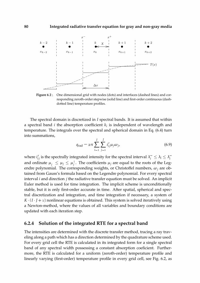
80 Integrated radiative transfer equation for gray and non-gray media
k − 1 k + 1k − 2 k + 2
xk−2 xk−1 xk+1 xk+2
T (x)
k
xk
X
x− x+
∆x
Figure 6.2 One dimensional grid with nodes (dots) and interfaces (dashed lines) and cor-responding zeroth-order stepwise (solid line) and first-order continuous (dash-dotted line) temperature profiles.
The spectral domain is discretized in I spectral bands. It is assumed that withina spectral band i the absorption coefficient ki is independent of wavelength andtemperature. The integrals over the spectral and spherical domain in Eq. (6.4) turninto summations,
qrad π
I
i
J
j
i ′i jµ jω j, (6.9)
where i ′i j is the spectrally integrated intensity for the spectral interval λ i ≤ λi ≤ λ i
and ordinate µ j ≤ µ j ≤ µ j . The coefficients µ j are equal to the roots of the Leg-
endre polynomial. The corresponding weights, or Christoffel numbers, ω j are ob-tained from Gauss’s formula based on the Legendre polynomial. For every spectralinterval i and direction j the radiative transfer equation must be solved. An implicitEuler method is used for time integration. The implicit scheme is unconditionallystable, but it is only first-order accurate in time. After spatial, spherical and spec-tral discretization and integration, and time integration if necessary, a system ofK · I · J
nonlinear equations is obtained. This system is solved iteratively usinga Newton-method, where the values of all variables and boundary conditions areupdated with each iteration step.
6.2.4 Solution of the integrated RTE for a spectral band
The intensities are determined with the discrete transfer method, tracing a ray trav-eling along a path which has a direction determined by the quadrature scheme used.For every grid cell the RTE is calculated in its integrated form for a single spectralband of any spectral width possessing a constant absorption coeficient. Further-more, the RTE is calculated for a uniform (zeroth-order) temperature profile andlinearly varying (first-order) temperature profile in every grid cell, see Fig. 6.2, as

6.2 Theory 81
was done previously by Cumber [32] for a gray absorption coefficient.Radiation within a spectral band λ i ≤ λi ≤ λ
i traveling along a path is altereddue to absorption and emission of radiation. When the intensity is integrated overthat band with constant absorption coefficient ki the recurrence relation Eq. (6.6)becomes,
i ′i j i ′i j exp
ki S j S j
s
λ
i
λ λ i
kii ′bλ
s exp
kiS j s dλds, (6.10)
with S j X/µ j
the pathlength in direction j, Fig. 6.1 (right).
The source term can be written as the difference between two integrals withlower boundary at λ . The integral with upper boundary at λ λ
i becomes
I i j
S j
s
λ
i
kii ′bλ
s exp
kiS j s dλds. (6.11)
The other spectral integral I i j has the upper boundary at λ λ i . The radiativeenergy that is emitted by the element within spectral interval
, λ
i is a fraction ofthe blackbody intensity,
i ′b λ
i F λ
i Ti ′b, (6.12)
where the blackbody intensity is,
i ′b σn
rπ
T, (6.13)
with σ = Boltzmann’s constant = 5.67051· W/mK and nr the index of refrac-tion. The fraction of the blackbody intensity that is emitted within the spectral band ≤ λ ≤ λ
i is given by e.g. Siegel et al. [122] as,
λ
i i ′bλ
dλ
i ′b F λ
i T
π
n
exp nζ n
(
ζ ζ
n ζ
n
n
)
, (6.14)
with ζ C/λ i T and C 0.01438769 mK. In order to use a boundary condition
at s S j later, the coordinate transformation ξ S j s is applied and Eq. (6.11)becomes:
I i j ki
S j
ξ
λ
i
i ′bλ
ξ dλ exp
kiξ dξ
ki S j
ξ F λ
i Tξ i ′b
ξ exp
kiξ dξ . (6.15)
The source term depends on Tξ , the temperature profile along a ray traveling
through the plate, and is considered uniform, resulting in a stepwise zeroth-ordertemperature profile (Fig. 6.2, solid line), or linear, resulting in a continuous first-order temperature profile (Fig. 6.2, dash-dotted line).

82 Integrated radiative transfer equation for gray and non-gray media
For a zeroth-order temperature profile the source term is relatively easy to com-pute because the blackbody emission of the spectral band
, λ
i is constant alongpath S j. The integrated source term is in that case,
I i j F λ
i Ti ′bT (
exp( kiS j
))
, (6.16)
which is quantified by Eqs. (6.13), (6.14), in which T is the uniform temperature.For of a first-order temperature profile the derivation of the source term is given
below. If β T T /S j ∆T/S j is the temperature gradient, see Fig. 6.1 (right),then T T
βs T βξ. So, T T at ξ S j (s ) and T T at ξ
(s S j). The linear temperature profile is applied in both i ′b and F λ
i T. The productF λ
i Tξ i ′b
ξ is then written as,
F λ
i Tξ i ′b
ξ
π
σnr
π
[
n
nexp
(
nC
λ i T
)((
C
λ i T
)
n
(
C
λ i T
)
n
(
C
λ i T
)
n
)
T
]
σnr
π
[
n
nexp
(
nC
λ iT βξ
)
m
Amnξm
]
. (6.17)
The coefficients Amn are given by:
An (
C
λ i
)
T
n
(
C
λ i
)
T
n
(
C
λ i
)
T
nT
,
An (
C
λ i
)
β
n
(
C
λ i
)
βT
n
(
C
λ i
)
βT
nβT
,
An
n
(
C
λ i
)
β
n
(
C
λ i
)
βT
nβT
,
An
n
(
C
λ i
)
β
nβT,
An
nβ. (6.18)
For m , , , ..., Amn . These coefficients have to be calculated for every n. Adifficulty is the /
T βξ in the exponent of Eq. (6.17). This factor can be written
as a Taylor polynomial forβS j
∆T < T,
T
T βξ
r
βξ rTr
. (6.19)
With the substitution of Eq. (6.19) in Eq. (6.17) and subsequently in Eq. (6.15) an exactsolution for the source term of an element with a linear temperature profile is found

6.3 Discussion 83
for a single wavelength band i with constant absorption coefficient ki. However, itcan be shown that for optically thick elements (kiS j > ) the solution, Eq. (6.15),does not converge under all conditions. To overcome this problem, a small error isallowed by cutting off the series of Eq. (6.19) after the linear term. The error thatoriginates is small as long as
∆T/T
is relatively small, and even decreases rapidly
for large ki S j. The exponent in Eq. (6.17) is rewritten as,
exp
(
nC
λ iT βξ
)
exp
(
r
Bnrξr
)
' expBn
Bnξ , (6.20)
with Bnr nCβr/λ
i Tr , so Bn nC/λ
i T and Bn Bnβ/T. ThenEq. (6.17) becomes:
F λ
i Tξ i ′b
ξ ' σn
rπ
n
n
(
m
Amnξm
)
expBn
Bnξ
σnr
π
n
expBn
n
(
m
Amnξm exp
Bnξ
)
(6.21)
This solution is substituted into Eq. (6.15),
I i j ' σn
r ki
π
n
expBn
n S j
ξ
(
m
Amnξm
)
exp
Bn ki ξ dξ
σnr ki
π
n
expBn
n
(
m
A m n
S j
ξ ξm exp
Bn ki ξ dξ
)
.(6.22)
The expression for the definite integral is given in App. A, and subsequently Eq. (6.22)is written in terms of γ-functions,
I i j ' σn
r ki
π
n
expBn
n
(
m
A m n
γ(
m ,ki Bn S j
)
ki Bn m
)
. (6.23)
The γ-function depends on the values of ki, S j and Bn, and is outlined in App. A.
6.3 Discussion
This section discusses the relative error of the radiative and conductive heat fluxand the relative error and computation times of its origin, the radiative source termof the RTE. First, three model problems are discussed in which a linear, quadratic,and third order polynomial are used as stationary temperature profiles in a one-dimensional plate. Inaccuracies of the radiative and conductive heat fluxes areshown for different discretization degrees and optical thicknesses. The error in theradiative heat flux originates from inaccuracies in the computation of the source

84 Integrated radiative transfer equation for gray and non-gray media
term of the integrated RTE. In the second subsection the relative errors and com-putation times of this source term are quantified when using the first-order andsecond-order method. The third subsection shows more practical stationary andtime dependent situations for gray and non-gray media.
6.3.1 A model problem: heat flux inaccuracies
A combined conduction-radiation model problem of a one-dimensional gray plateis considered. The physical and thermodynamic properties are based on the prop-erties of quartz glass. The thermal conductivity coefficient, specific heat capacityand density are considered to be constant in temperature. The thermal conductivitycoefficient is λ . W/mK, the specific heat capacity is c J/kgK, and thedensity is ρ kg/m. The plate thickness (Fig. 6.1 left) is D mm. Thespectral absorption curve of the plate contains of a single wide spectral band withλ
, so that all radiation is emitted and absorbed within the spectral range ofthe band, and therefore the plate is assumed to be gray. The absorption coefficientof this band is varied between ≤ k ≤ m so that ≤ kD ≤ . Theconstant refraction index is taken unity so that there is no specular reflection.
Three cases are considered, where in each case the plate possesses a stationarytemperature profile with a linear, quadratic, and third-order polynomial shape, seeFig 6.3 (top left). The temperature profiles are implemented on a one-dimensionalequidistant mesh of varying discretization degree. The instant radiative and con-ductive heat fluxes are determined in the center of the plate at x D/. The conduc-tive fluxes are calculated using a first-order numerical method, while the radiativefluxes are calculated using the zeroth-order and first-order method, as described inthe previous section, using Eqs. (6.9), (6.10), (6.16), and (6.23).
The error in the conductive and radiative heat flux depends on the discretizationdegree of the corresponding meshes. A similar mesh is taken for the conductive andradiative heat transfer computations. The absolute error introduced by the compu-tation of either the radiative or conductive heat flux is compared with the absolutetotal heat flux, i.e. the sum of the conductive and radiative heat flux. Then, therelative error of the conductive heat flux is,
εcond ∣
∣
∣
∣
∣
qcond qexactcond
qexacttotal
∣
∣
∣
∣
∣
, (6.24)
and the relative error of the radiative heat flux is
εrad ∣
∣
∣
∣
∣
qrad qexactrad
qexacttotal
∣
∣
∣
∣
∣
, (6.25)
where qexacttotal qexact
cond qexact
rad . The heat fluxes qexactcond and qexact
rad are determined on amesh of 250 elements, and qexact
rad is calculated using the first-order method. The heatfluxes qcond and qrad are both determined on meshes of 10 and 50 elements.

6.3 Discussion 85
0 0.2 0.4 0.6 0.8 11800
2000
2200
2400
2600
x/D [−]
T [K
]
10−1
100
101
102
103
10−10
10−8
10−6
10−4
10−2
100
kD [−]
ε [−
]
K = 10
K = 50
K = 10 K = 50
10−1
100
101
102
103
10−10
10−8
10−6
10−4
10−2
100
kD [−]
ε [−
]
K = 10
K = 50 K = 10
K = 50
K = 10 K = 50
10−1
100
101
102
10310
−6
10−5
10−4
10−3
10−2
10−1
100
kD [−]
ε [−
]
K = 10
K = 50
Figure 6.3 Linear (solid line), quadratic (dashed line) and third order (dashed-dotted line)polynomial temperature profiles (top left). Nondimensional error ε at x
D/ for radiative fluxes calculated with the first-order method (solid lines)and zeroth-order method (dashed lines) and for the conductive fluxes (dashed-dotted lines) for discretization degrees of K and K , using the linear(top right), quadratic (bottom left) and third order (bottom right) temperatureprofile.
Fig 6.3 (top right), (bottom left), and (bottom right) show the relative conductiveand radiative heat flux error at x D/ when the plate experiences a temperatureprofile that has a linear, quadratic and third-order polynomial shape respectively, asgiven in Fig 6.3 (top left). For a linear temperature profile, Fig 6.3 (top right) showsthat the error of the conductive fluxes is generally small, for both discretization de-grees of K and K . The error of the radiative heat fluxes calculated withthe first-order method is also low and comparable to the error of the conductivefluxes. However, the error of the radiative heat fluxes calculated with the zeroth-order method is orders of magnitude larger than the error of the conductive fluxes,especially when the plate is optically thick, i.e. when kD is large. The radiativeerror decreases with increasing discretization degree but remains much larger thanthe error of the conductive fluxes, and therefore it is the dominant error in a platewith linear temperature profile. For a quadratic temperature profile, it is shown inFig 6.3 (bottom left) that the conductive heat flux is calculated accurately, close to thenumerical accuracy. The relative errors of the radiative heat fluxes when using the

86 Integrated radiative transfer equation for gray and non-gray media
zeroth-order and first-order method are generally low and comparable to each otherfor small kD, but are relatively large compared to the error of the conductive flux.For increasing opacity the radiative heat flux error calculated with the zeroth-ordermethod increases even more, while the radiative heat flux error calculated with thefirst-order method decreases to values closer to the error of the conductive flux. Forthe third-order temperature profile, Fig 6.3 (bottom right) shows that using a first-order numerical method to calculate the conductive heat fluxes leads to significantinaccuracies. It can be derived that the conductive heat flux error introduced by athird-order temperature profile is equal to
qcond qexactcond
∆x
dTdx
. (6.26)
Increasing the discretization degree, increases the accuracy of the conductive heatflux quadratically. The error of the radiative heat flux calculated with the zeroth-order or first-order method is comparable to the error of the conductive flux forsmall to intermediate optical thicknesses. However, for kD , the optically densecase, the error of the radiative heat flux calculated with the zeroth-order methodbecomes dominant, while the error resulting from the first-order method is ordersof magnitude smaller than the error of the conductive flux.
It is concluded that the relative error of the radiative heat flux calculated withthe zeroth-order method is relatively small for optically thin media, but increasesrapidly with increasing opacity. Then, the resulting error is orders of magnitudelarger than the error of the conductive fluxes, no matter the polynomial order of thetemperature profile. Increasing the discretization degree, increases the accuracy ofboth the radiative and conductive flux, so that the error of the radiative flux remainsdominant. The relative error of the radiative heat flux calculated with the first-ordermethod is small or comparable to the error of the conductive heat flux. Increasingthe opacity, increases the accuracy of the radiative flux rapidly, so that the errorof the conductive flux becomes dominant. The difference in accuracy between theradiative heat fluxes calculated with the zeroth-order and first-order method arisesfrom the difference in the computation of radiative source term of the integratedRTE. The difference in the computation of a radiative source term with the zeroth-order and first-order method is investigated in the next subsection.
6.3.2 The radiative source term
In the previous subsection it was shown that for optically dense materials there isa deviation between the radiative fluxes calculated with the zeroth-order and first-order method. The radiative fluxes were determined at the center of a plate of thick-ness D, that was discretized in K elements. Apart from the boundary elements, eachelement had a width of ∆x x x X, see Fig. 6.1 and 6.2. In this subsectionthe source term of the integrated RTE for a ray traveling through an element with

6.3 Discussion 87
0 0.02 0.04 0.06 0.08 0.110
−6
10−5
10−4
10−3
10−2
10−1
100
∆T/T1 [−]
ε [
−]
zeroth−order
first−order
0 0.02 0.04 0.06 0.08 0.110
−1
100
101
102
103
104
∆T/T1 [−]
τ /τ
ref
[−]
zeroth−order
first−order
Figure 6.4 Relative error ε (left) and computation time τ/τref (right) of the radiativesource term calculated with the zeroth-order and first-order method as func-tion of nondimensional temperature difference ∆T/T for optical thicknesseskS
(dashed-dotted lines), kS (dashed lines), kS (solidlines). Reference computation time τref . ·
equals the time to cal-culate a single source term with the zeroth-order method and ∆T/T andkS ..
half width X ∆x/ is calculated for a range of optical thicknesses. The direc-tion of the ray makes an angle θ with the x-axis, see Fig. 6.1 (right), and thereforethe path-length S ≥ X. The source term of the integrated RTE for a ray travelingalong a path s through the element, entering the element at path-coordinate s
and leaving the element at s S is calculated, and is compared to the solution of acomputation on a highly discretized mesh, and therefore more or less exact solution.The error relative to the exact solution and the relative computation times of a sin-gle source term calculated with the zeroth-order and first-order method are given.The optical thicknesses studied, now not based on the plate thickness but based onthe fixed path-length S of a single element and varying absorption coefficient k, arekS , kS , and kS . The temperature at s is T, the temperature ats S is T K and ∆T T T is varied between and .
Fig. 6.4 (left) shows the relative error ε of the source term calculated with thezeroth-order method as function of typical temperature change ∆T/T. The sourceterm calculated with a zeroth-order temperature profile, Eq. (6.16), shows a signifi-cant error when temperature gradients are large. Moreover, if the penetration depthof the radiation is typically smaller than the path-length S, which is the case for op-tically dense materials with kS , the inaccuracies when using the zeroth-ordermethod are large. This is due to the fact that the magnitude of the source term in apoint is determined by the temperature in the vicinity of that point. In the zeroth-order method the source term at s S is calculated from the temperature at s S/
and not from the temperature at s S. As a result, the relative error increases withincreasing ∆T. A finer mesh decreases both kS and ∆T, result in a more accuratesolution.
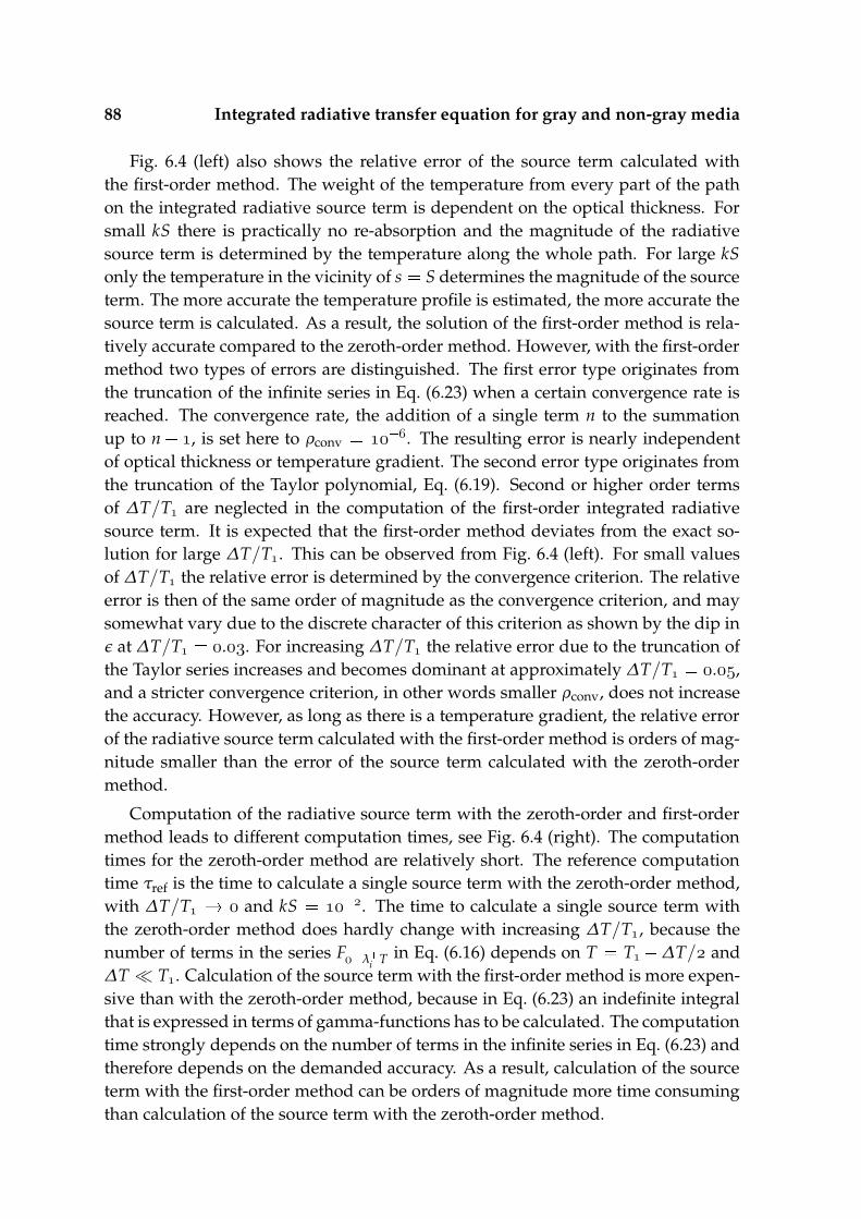
88 Integrated radiative transfer equation for gray and non-gray media
Fig. 6.4 (left) also shows the relative error of the source term calculated withthe first-order method. The weight of the temperature from every part of the pathon the integrated radiative source term is dependent on the optical thickness. Forsmall kS there is practically no re-absorption and the magnitude of the radiativesource term is determined by the temperature along the whole path. For large kSonly the temperature in the vicinity of s S determines the magnitude of the sourceterm. The more accurate the temperature profile is estimated, the more accurate thesource term is calculated. As a result, the solution of the first-order method is rela-tively accurate compared to the zeroth-order method. However, with the first-ordermethod two types of errors are distinguished. The first error type originates fromthe truncation of the infinite series in Eq. (6.23) when a certain convergence rate isreached. The convergence rate, the addition of a single term n to the summationup to n , is set here to ρconv . The resulting error is nearly independentof optical thickness or temperature gradient. The second error type originates fromthe truncation of the Taylor polynomial, Eq. (6.19). Second or higher order termsof ∆T/T are neglected in the computation of the first-order integrated radiativesource term. It is expected that the first-order method deviates from the exact so-lution for large ∆T/T. This can be observed from Fig. 6.4 (left). For small valuesof ∆T/T the relative error is determined by the convergence criterion. The relativeerror is then of the same order of magnitude as the convergence criterion, and maysomewhat vary due to the discrete character of this criterion as shown by the dip inε at ∆T/T .. For increasing ∆T/T the relative error due to the truncation ofthe Taylor series increases and becomes dominant at approximately ∆T/T .,and a stricter convergence criterion, in other words smaller ρconv, does not increasethe accuracy. However, as long as there is a temperature gradient, the relative errorof the radiative source term calculated with the first-order method is orders of mag-nitude smaller than the error of the source term calculated with the zeroth-ordermethod.
Computation of the radiative source term with the zeroth-order and first-ordermethod leads to different computation times, see Fig. 6.4 (right). The computationtimes for the zeroth-order method are relatively short. The reference computationtime τref is the time to calculate a single source term with the zeroth-order method,with ∆T/T and kS . The time to calculate a single source term withthe zeroth-order method does hardly change with increasing ∆T/T, because thenumber of terms in the series F λ
i T in Eq. (6.16) depends on T T ∆T/ and∆T T. Calculation of the source term with the first-order method is more expen-sive than with the zeroth-order method, because in Eq. (6.23) an indefinite integralthat is expressed in terms of gamma-functions has to be calculated. The computationtime strongly depends on the number of terms in the infinite series in Eq. (6.23) andtherefore depends on the demanded accuracy. As a result, calculation of the sourceterm with the first-order method can be orders of magnitude more time consumingthan calculation of the source term with the zeroth-order method.
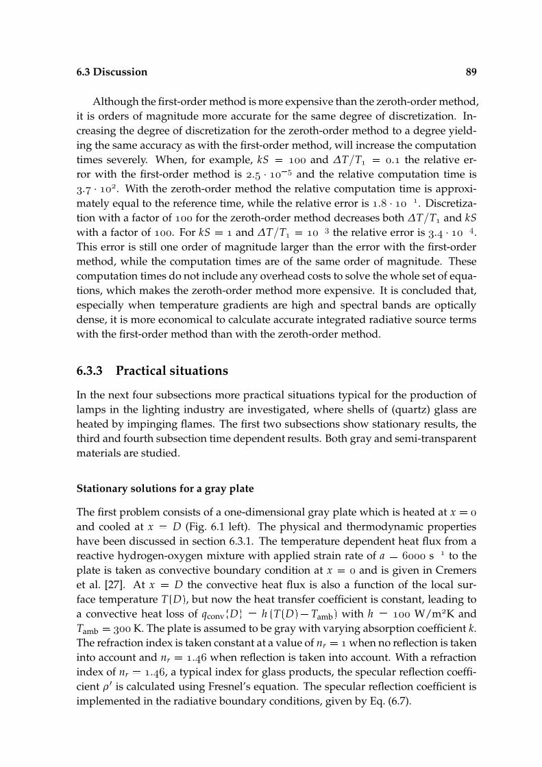
6.3 Discussion 89
Although the first-order method is more expensive than the zeroth-order method,it is orders of magnitude more accurate for the same degree of discretization. In-creasing the degree of discretization for the zeroth-order method to a degree yield-ing the same accuracy as with the first-order method, will increase the computationtimes severely. When, for example, kS and ∆T/T . the relative er-ror with the first-order method is . · and the relative computation time is. · . With the zeroth-order method the relative computation time is approxi-mately equal to the reference time, while the relative error is . · . Discretiza-tion with a factor of for the zeroth-order method decreases both ∆T/T and kSwith a factor of . For kS and ∆T/T the relative error is . · .This error is still one order of magnitude larger than the error with the first-ordermethod, while the computation times are of the same order of magnitude. Thesecomputation times do not include any overhead costs to solve the whole set of equa-tions, which makes the zeroth-order method more expensive. It is concluded that,especially when temperature gradients are high and spectral bands are opticallydense, it is more economical to calculate accurate integrated radiative source termswith the first-order method than with the zeroth-order method.
6.3.3 Practical situations
In the next four subsections more practical situations typical for the production oflamps in the lighting industry are investigated, where shells of (quartz) glass areheated by impinging flames. The first two subsections show stationary results, thethird and fourth subsection time dependent results. Both gray and semi-transparentmaterials are studied.
Stationary solutions for a gray plate
The first problem consists of a one-dimensional gray plate which is heated at x
and cooled at x D (Fig. 6.1 left). The physical and thermodynamic propertieshave been discussed in section 6.3.1. The temperature dependent heat flux from areactive hydrogen-oxygen mixture with applied strain rate of a s to theplate is taken as convective boundary condition at x and is given in Cremerset al. [27]. At x D the convective heat flux is also a function of the local sur-face temperature T
D , but now the heat transfer coefficient is constant, leading to
a convective heat loss of qconvD h
TD Tamb with h W/mK and
Tamb K. The plate is assumed to be gray with varying absorption coefficient k.The refraction index is taken constant at a value of nr when no reflection is takeninto account and nr . when reflection is taken into account. With a refractionindex of nr ., a typical index for glass products, the specular reflection coeffi-cient ρ ′ is calculated using Fresnel’s equation. The specular reflection coefficient isimplemented in the radiative boundary conditions, given by Eq. (6.7).
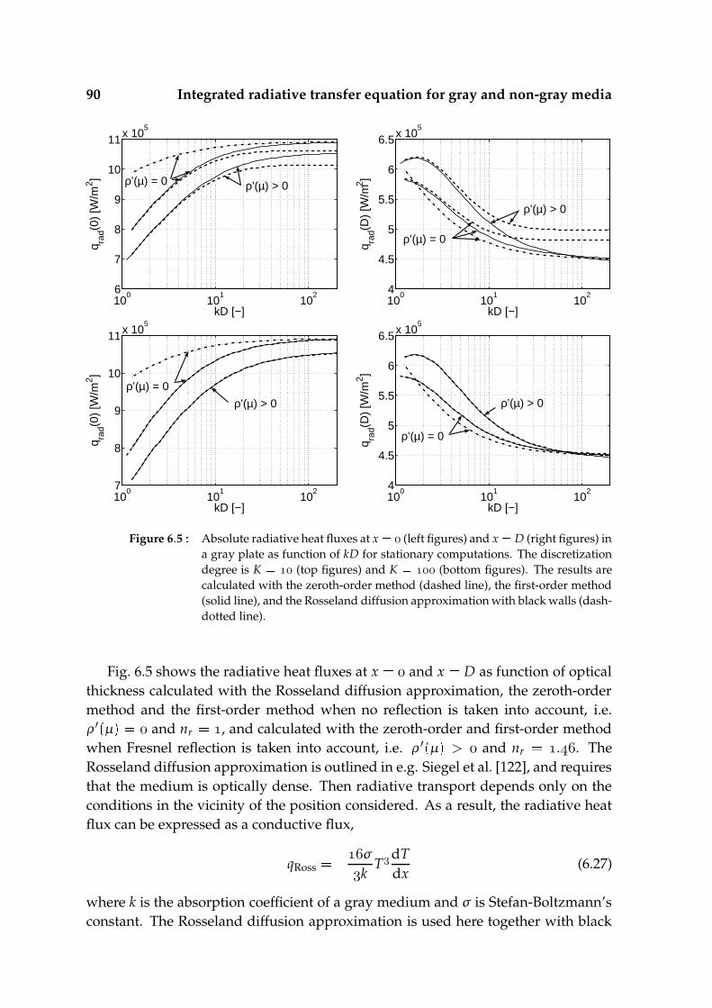
90 Integrated radiative transfer equation for gray and non-gray media
100
101
1026
7
8
9
10
11x 105
kD [−]
q rad(0
) [W
/m2 ]
ρ’(µ) > 0 ρ’(µ) = 0
100
101
1024
4.5
5
5.5
6
6.5x 10⁵
kD [−]
q rad(D
) [W
/m2 ]
ρ’(µ) > 0
ρ’(µ) = 0
100
101
1027
8
9
10
11x 105
kD [−]
q rad(0
) [W
/m2 ]
ρ’(µ) > 0
ρ’(µ) = 0
100
101
1024
4.5
5
5.5
6
6.5x 10⁵
kD [−]
q rad(D
) [W
/m2 ]
ρ’(µ) > 0
ρ’(µ) = 0
Figure 6.5 Absolute radiative heat fluxes at x (left figures) and x D (right figures) ina gray plate as function of kD for stationary computations. The discretizationdegree is K (top figures) and K (bottom figures). The results arecalculated with the zeroth-order method (dashed line), the first-order method(solid line), and the Rosseland diffusion approximation with black walls (dash-dotted line).
Fig. 6.5 shows the radiative heat fluxes at x and x D as function of opticalthickness calculated with the Rosseland diffusion approximation, the zeroth-ordermethod and the first-order method when no reflection is taken into account, i.e.ρ ′ µ and nr , and calculated with the zeroth-order and first-order methodwhen Fresnel reflection is taken into account, i.e. ρ ′ µ > and nr .. TheRosseland diffusion approximation is outlined in e.g. Siegel et al. [122], and requiresthat the medium is optically dense. Then radiative transport depends only on theconditions in the vicinity of the position considered. As a result, the radiative heatflux can be expressed as a conductive flux,
qRoss σ
kT dT
dx(6.27)
where k is the absorption coefficient of a gray medium and σ is Stefan-Boltzmann’sconstant. The Rosseland diffusion approximation is used here together with black

6.3 Discussion 91
Table 6.1 Relative computation times for stationary computations of a gray plate dividedin K elements, calculated with the zeroth-order method and the first-ordermethod.
K K K K
Zeroth-order method 1 4 56 802First-order method 16 58 613 8267
walls.In Fig. 6.5 results are shown for a plate divided in 10 and 100 elements. In
general, for small kD, the optically thin case, the radiative fluxes calculated withthe first-order method correspond to the fluxes calculated with the zeroth-ordermethod. For large kD, the optically thick case, the radiative fluxes calculated withthe first-order method correspond to the fluxes calculated with the diffusion approx-imation. For increasing K the difference between the zeroth-order and first-ordermethod decreases, until the two methods give a more or less similar radiative heatflux for K . The radiative heat flux calculated with the Rosseland or first-ordermethod remains relatively unchanged with increasing K. Furthermore, specular re-flection decreases the total radiative heat flux at x . As a result, the stationarytemperature increases in the whole plate, which leads to a higher radiation heat lossat x D.
The same calculations are performed for K and K and Table 6.1 showsthe overall relative computation times. For the optically thin case the zeroth-ordermethod is more economical than the first-order method. For the optically thickcase, when using the zeroth-order method, the plate needs to be discretized to amuch higher degree to obtain a comparable accuracy as obtained with the first-ordermethod. Then the zeroth-order method becomes more expensive than the first-ordermethod.
Stationary solutions for a semi-transparent plate
Thus far, the zeroth-order and first-order methods have only been applied to a sin-gle band, that was taken wide enough that the medium can be considered gray. Inreality there are only few materials that can be considered gray. Semi-transparentmedia, like glass for instance, have a region of the spectrum where they can be con-sidered transparent, while they have another region of the spectrum, the infrared re-gion for glass, where they can be considered opaque. A two-band absorption modelwith varying cut-off wavelength, λc, is used. The optical thickness for wavelengthsshorter than the cut-off wavelength is equal to kD , while the optical thick-ness for wavelengths longer than the cut-off wavelength is equal to kD . As aresult, for short cut-off wavelengths, λc, the material is absorbing for radiation fromthe largest part of the spectrum, while for long λc the material can be consideredtransparent.
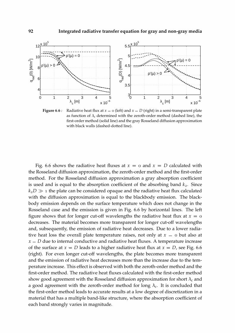
92 Integrated radiative transfer equation for gray and non-gray media
0 1 2 3 4 5x 10
−6
4
6
8
10
12x 105
λc [m]
q rad(0
) [W
/m2 ]
ρ’(µ) = 0
ρ’(µ) > 0
0 1 2 3 4 5x 10
−6
3
3.5
4
4.5
5
5.5x 10⁵
λc [m]
q rad(D
) [W
/m2 ] ρ’(µ) = 0
ρ’(µ) > 0
Figure 6.6 Radiative heat flux at x (left) and x D (right) in a semi-transparent plateas function of λc determined with the zeroth-order method (dashed line), thefirst-order method (solid line) and the gray Rosseland diffusion approximationwith black walls (dashed-dotted line).
Fig. 6.6 shows the radiative heat fluxes at x and x D calculated withthe Rosseland diffusion approximation, the zeroth-order method and the first-ordermethod. For the Rosseland diffusion approximation a gray absorption coefficientis used and is equal to the absorption coefficient of the absorbing band k. SincekD the plate can be considered opaque and the radiative heat flux calculatedwith the diffusion approximation is equal to the blackbody emission. The black-body emission depends on the surface temperature which does not change in theRosseland case and the emission is given in Fig. 6.6 by horizontal lines. The leftfigure shows that for longer cut-off wavelengths the radiative heat flux at x
decreases. The material becomes more transparent for longer cut-off wavelengthsand, subsequently, the emission of radiative heat decreases. Due to a lower radia-tive heat loss the overall plate temperature raises, not only at x but also atx D due to internal conductive and radiative heat fluxes. A temperature increaseof the surface at x D leads to a higher radiative heat flux at x D, see Fig. 6.6(right). For even longer cut-off wavelengths, the plate becomes more transparentand the emission of radiative heat decreases more than the increase due to the tem-perature increase. This effect is observed with both the zeroth-order method and thefirst-order method. The radiative heat fluxes calculated with the first-order methodshow good agreement with the Rosseland diffusion approximation for short λc anda good agreement with the zeroth-order method for long λc. It is concluded thatthe first-order method leads to accurate results at a low degree of discretization in amaterial that has a multiple band-like structure, where the absorption coefficient ofeach band strongly varies in magnitude.
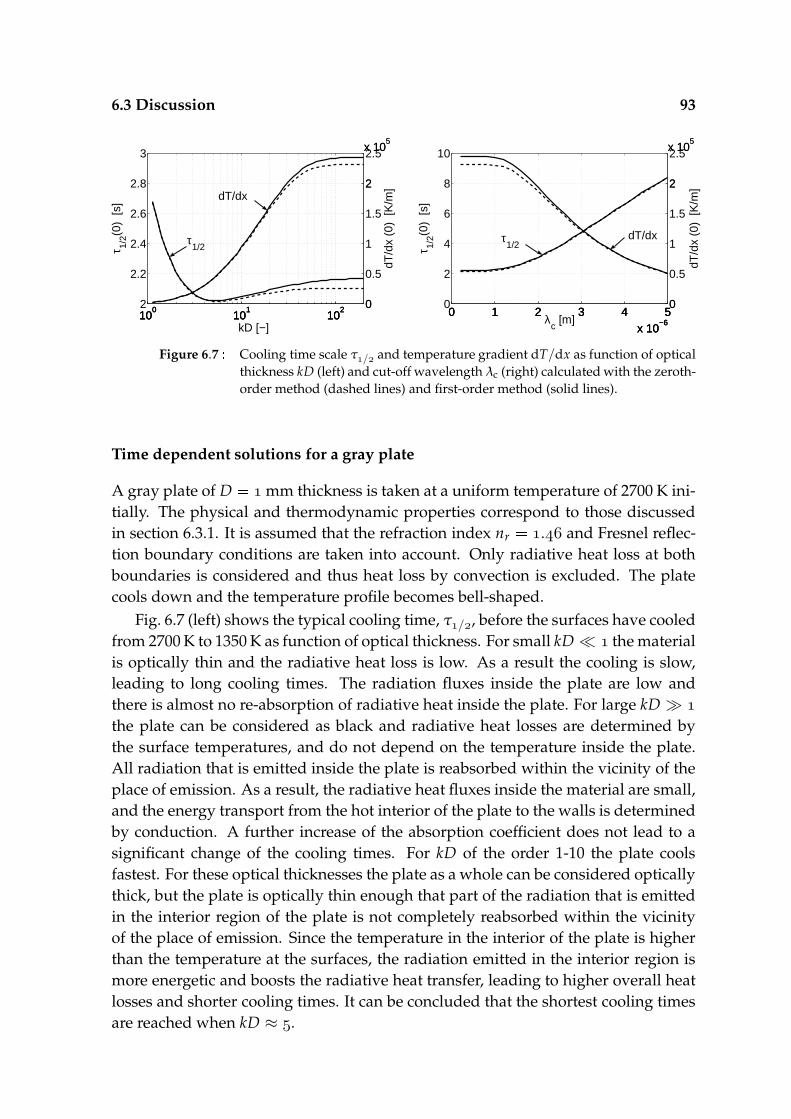
6.3 Discussion 93
100
101
1022
2.2
2.4
2.6
2.8
3
τ 1/2(0
) [s
]
kD [−]10
010
110
2 0
2
x 105
100
101
102 0
0.5
1
1.5
2
2.5x 10⁵
dT/d
x (0
) [K
/m]
τ1/2
dT/dx
0 1 2 3 4 5x 10
−6
0
2
4
6
8
10
τ 1/2(0
) [s
]
λc [m]
0 1 2 3 4 5x 10
−6
0
2
x 105
0 1 2 3 4 5x 10
−6
0
0.5
1
1.5
2
2.5x 10⁵
dT/d
x (0
) [K
/m]
τ1/2
dT/dx
Figure 6.7 Cooling time scale τ/ and temperature gradient dT/dx as function of opticalthickness kD (left) and cut-off wavelength λc (right) calculated with the zeroth-order method (dashed lines) and first-order method (solid lines).
Time dependent solutions for a gray plate
A gray plate of D mm thickness is taken at a uniform temperature of 2700 K ini-tially. The physical and thermodynamic properties correspond to those discussedin section 6.3.1. It is assumed that the refraction index nr . and Fresnel reflec-tion boundary conditions are taken into account. Only radiative heat loss at bothboundaries is considered and thus heat loss by convection is excluded. The platecools down and the temperature profile becomes bell-shaped.
Fig. 6.7 (left) shows the typical cooling time, τ/, before the surfaces have cooledfrom 2700 K to 1350 K as function of optical thickness. For small kD the materialis optically thin and the radiative heat loss is low. As a result the cooling is slow,leading to long cooling times. The radiation fluxes inside the plate are low andthere is almost no re-absorption of radiative heat inside the plate. For large kD
the plate can be considered as black and radiative heat losses are determined bythe surface temperatures, and do not depend on the temperature inside the plate.All radiation that is emitted inside the plate is reabsorbed within the vicinity of theplace of emission. As a result, the radiative heat fluxes inside the material are small,and the energy transport from the hot interior of the plate to the walls is determinedby conduction. A further increase of the absorption coefficient does not lead to asignificant change of the cooling times. For kD of the order 1-10 the plate coolsfastest. For these optical thicknesses the plate as a whole can be considered opticallythick, but the plate is optically thin enough that part of the radiation that is emittedin the interior region of the plate is not completely reabsorbed within the vicinityof the place of emission. Since the temperature in the interior of the plate is higherthan the temperature at the surfaces, the radiation emitted in the interior region ismore energetic and boosts the radiative heat transfer, leading to higher overall heatlosses and shorter cooling times. It can be concluded that the shortest cooling timesare reached when kD ≈ .
94 Integrated radiative transfer equation for gray and non-gray media
Fig. 6.7 (left) also shows dT/dx at x for t τ/. For small kD emittedradiation is hardly reabsorbed, leading to uniform cooling and small temperaturegradients. For kD of the order 1-10 the radiative heat is mainly extracted from theregions close to the walls, leading to larger temperature gradients. Both conduc-tive and radiative fluxes redistribute energy from the hot center to the cold walls,suppressing the temperature gradients. For kD redistribution of energy byconduction remains, but radiative energy fluxes vanish, leading to the largest tem-perature gradients.
Time dependent solutions for a semi-transparent plate
In this subsection, the optical properties of the plate have a two-band structure, asdiscussed in section 6.3.3. Fig. 6.7 (right) shows the typical cooling time τ/ andtemperature gradient dT/dx at x as function of cut-off wavelength λc. For shortcut-off wavelengths the plate acts as a blackbody, the cooling times are relativelyshort and the temperature gradients are large. For longer cut-off wavelengths, theplate becomes more transparent, the cooling times are longer and the temperaturegradients are less steep. Radiation emitted within the transparent band is hardlyreabsorbed while traveling through the plate, and does not lead to redistribution ofenergy by radiation. Radiation emitted within the absorbing band is reabsorbed inthe vicinity of its origin, and therefore does also not enhance the redistribution ofenergy by radiation. As a result, a minimum in cooling time, as observed in the graycase with varying absorption coefficient, is not observed here.
6.4 Conclusion
Radiative transfer is of major importance in many transient heating and coolingprocesses. At high temperatures, radiative heat loss is the dominant heat loss mech-anism in gray opaque or semi-transparent media. Many analytical and numericalmethods have been developed in the past, and some of them are often applied inCFD codes. One of the numerical solution techniques that is often used, is the finitevolume method, in which the energy conservation equation is written in terms ofenergy fluxes. The radiative energy fluxes are determined using the discrete transfermethod in conjugation with the discrete ordinate method, which uses the radiativetransfer equation (RTE) in integral form. This paper shows the nearly analytical so-lution of the RTE in integral form, using a stepwise zeroth-order temperature profile(zeroth-order method) and a continuous first-order temperature profile (first-ordermethod) as was previously done by Cumber [32] for a gray non-scattering mediumand extended by Farhat and Radhouani [42] for a scattering medium. In this pa-per the RTE is solved for a non-gray and non-scattering medium with a band-likeabsorption coefficient. The RTE is then solved for a single band of arbitrary spec-tral width possessing a constant absorption coefficient. A combined conduction-
6.4 Conclusion 95
radiation model problem of a one-dimensional plate with a prescribed temperatureprofile of linear, quadratic, or third-order polynomial shape is studied, and the con-ductive and radiative heat flux errors relative to the total heat flux are determined.The relative error of the radiative heat flux calculated with the first-order methodis small or comparable to the error of the conductive heat flux for all optical thick-nesses, while the relative error of the radiative heat flux calculated with the zeroth-order method is small for optically thin media, but increases rapidly for increasingopacity. Although the computation of a single RTE with the first-order method is rel-atively expensive compared to the computation with the zeroth-order method, thefirst-order method gives accurate results on a course mesh with high temperaturegradients. The method is therefore easily applicable within an existing computa-tional fluid dynamics solver. Results are also accurate within a band-like spectralstructure with strongly varying absorption coefficient, typical for semi-transparentmaterials.
More practical cases have also been considered. Stationary and transient coolingresults of a gray plate with varying optical thickness and a semi-transparent platewith varying cut-off wavelength were studied. In the gray transient cooling case, aminimum cooling time is observed for kD ≈ . Then, the plate as a whole can beconsidered optically thick, but the plate is optically thin enough that part of the ra-diation that is emitted in the interior region of the plate is not completely reabsorbedwithin the vicinity of the place of emission. An increasing opacity of the materialleads to larger temperature gradients, with a maximum gradient when the materialacts as a blackbody. In the semi-transparent case, with a two-band absorption modelwith variable cut-off wavelength, no minimum cooling time is observed. However,the bands studied are either optically thin or optically thick and not of the orderkiD ≈ .

96 Integrated radiative transfer equation for gray and non-gray media
Chapter7From heat transferpredictions towards burnerdesign
This thesis is part of the project ’Pushing the Limits of Heat Transfer by Oxy-Fuel’.The project is a joint effort of Philips Lighting B.V. and Eindhoven University ofTechnology to improve the heat transfer of impinging oxy-fuel flames to (quartz)-glass products, by performing an in-depth study on the heat transfer phenomenainvolved in the heating process. With this knowledge, burner and process designcan be optimized. Section 7.1 shows the path from burner design to heat transfer,and a number of topics mentioned in section 7.1 that influence this path are dis-cussed in the subsequent sections. In section 7.2 it is shown how the choice of a fueltype influences the flame, and consequently influences the convective heat transferrate. Section 7.3 indicates how heat release by chemistry near the stagnation surfaceadds to the convective heat transfer. The maximum temperature a glass product canachieve is mainly determined by radiative heat loss of the product, which is dis-cussed in the last section. It should be stated once again that the research has beenconfined to small laminar oxy-fuel flames impinging against a glass target. This con-figuration is very common in the lamp making process and represents many otherconfigurations.
7.1 Introduction
The coupling between the industrial set-up and physical parameters that influencethe heat transfer phenomena is presented schematically in Fig. 7.1. In this figure, thestagnation flame is divided in two regions; the flame region and the stagnation layerregion. These two regions are linked by several physical parameters. Changes in theburner set-up influence the physical parameters, and hence influence the heat trans-fer phenomena. Among the parameters that can be changed in the burner set-upare nozzle diameter, velocity of the gas in the nozzle exit, fuel composition, etc. Ad-justing the burner set-up parameters changes the physical parameters of the burnedgas. Therefore, it is important to predict how,
1. the fuel gas and unburned nozzle exit velocity determine the velocity, chemical

98 From heat transfer predictions towards burner design
Nozzle diameter DnGas velocity at nozzle outlet u
Gas temperature at nozzle outlet T
Gas composition at nozzle outlet Xi
Distance burner to product L
Burner set-up parameters
Physical parametersWidth flame jet Rj
Distance flame tip to product H
Velocity flame jet u
Composition flame jet Xi
Temperature flame jet T
Heat transfer phenomenaConvective heat transferThermochemical heat release (equilibrium)Thermochemical heat release (surface)Radiative heat transfer
T, Xi, L
Rj, u, T, Xi, H
Dn, u
Stag
natio
nla
yer
Flam
e
Glass type, Cut-off wavelength λc
Surface temperature Ts
Figure 7.1 Diagram from burner setup parameters to physical parameters to heat transferphenomena.
composition and temperature of the burned gas,
2. the burner geometry, fuel gas and nozzle exit velocity determine the jet widthof the burned gas, i.e. the hot spot of the impinging flame.
The physical parameters Rj, u, T, Xi and H are used as inlet conditions for thestagnation layer. The heat transfer rate to the product is then determined by theheat transfer of the stagnation layer to the product. The heat transfer rate from thestagnation layer to the product can be divided in a convective heat transfer, and anadditional heat transfer due to chemical recombination at and near the object sur-face, known as surface and equilibrium thermochemical heat release respectively,
qstagnation layer qconvection qTCHR aTCHR · qconvection (7.1)
with qconvection the convective heat transfer rate of a hot inert gas impinging againstthe stagnation plane, and qTCHR the additional heat transfer due to surface and equi-librium thermochemical heat release. Thermochemical heat release is implementedby a heat transfer multiplication factor aTCHR. It is important to predict how,
3. the velocity of the burned gas and distance from the flame tip to the stagnationsurface determine the convective heat transfer rate,
4. the burned gas composition and stagnation plane temperature determine theaddition of thermochemical heat release to the convective heat transfer.

7.2 Fuel gas 99
Finally, depending on the chosen glass type, the glass has certain optical proper-ties, here simply indicated by the cut-off wavelength λc. When the glass reachesa high temperature (>1700 K), radiative heat loss becomes the dominant heat lossmechanism. Therefore, it is important to predict how,
5. the cut-off wavelength determines the heat loss of the glass and as a result themaximum attainable temperature of the glass product.
Influences of flow effects on the heat transfer rate will be discussed in a seperatethesis by M.J. Remie. That thesis shows a part of topic one, and will discuss thesecond and third topic. The results shown in this thesis focus on chemistry effectsin the chemically reacting flow, and radiative heat transport in the glass. The first,fourth and fifth topic treat chemistry and radiation effects and will be treated insections 7.2, 7.3 and 7.4 respectively.
7.2 Fuel gas
Table 7.1 Properties of stoichiometric oxy-fuel flames. Given are the molar stoichiomet-ric fraction s, laminar burning velocity sL, adiabatic flame temperature Tad,density ratio of the unburned and burned mixture τ , total enthalpy availablein the initial mixture ∆ H, and sensible enthalpy of the adiabatically burnedmixture ∆ Hs
ad.
Oxy-Fuel Mechanism s sL Tad τ ∆ H ∆ Hsad
mixture [cm/s] [K] [-] [kJ/mole] [kJ/mole]H-O Smooke [124] 0.5 997 3079 8.31 161 106CH-O GRI 3.0 [123] 2 306 3052 12.6 268 159N.G.-O GRI 3.0 [123] 1.745 290 3031 12.4 255 156CH-O San Diego [115] 3.5 356 3083 14.5 318 178CH-O San Diego [115] 5 353 3093 15.4 341 188CH-O San Diego [115] 2.5 868 3341 14.1 359 153
This section discusses topic 1 from section 7.1. Chosing the fuel composition(Xi), unburned gas temperature (T) and nozzle exit gas velocity (u) determinesthe plug flow velocity (u), temperature (T), composition (Xi) and therefore thesensible enthalpy (∆ Hs
) and chemical enthalpy (∆ Hc) of the burned gas, as pre-
sented schematically in Fig. 2.1 and 7.1.First, the plug flow velocity of the burned gas u will be determined for different
oxy-fuel mixtures. The plug flow velocity of the burned gas is an important param-eter for the heat transfer rate, and how u influences the convective heat transferrate will be discussed extensively in a seperate thesis by M.J. Remie. In general it

100 From heat transfer predictions towards burner design
0 1000 2000 3000 4000 50000
2000
4000
6000
8000
10000
12000
14000
u1 [cm/s]
u 2 [cm
/s]
C2H
6−O
2
C3H
8−O
2
H2−O
2
C2H
2−O
2
CH4−O
2 flash back no flash back
Figure 7.2 Plug flow velocity of the burned gas u as function of nozzle exit velocity u
for various oxy-fuel mixtures. Values for the laminar burning velicites sL anddensity ratio τ are presented in table 7.1
can be stated that the heat transfer rate is higher when u is higher. As was given byEq. (2.41),
u/u τ
[
√
(
(
sL
u
))τ τ
τ
]
and drawn in Fig. 2.2, the velocity u is dependent on the velocity of the plug flowin the nozzle exit u, laminar burning velocity sL, and density ratio of the unburnedand burned mixture τ . Values of the laminar burning velocity sL and density ratio τ
are presented in table 7.1 for various mixtures. For the natural gas-oxygen mixture(N.G.-O), Groningen Gas (The Netherlands) is chosen as fuel gas with XCH .,XCH
., XCO ., and XN . in volume or molar fractions. In Fig 7.2
u is presented as function of u for various stoichiometric oxy-fuel mixtures. Allcurves start at a minimum velocity u sL. Velocity u sL is the theoreticalabsolute limit for flash back, and in the region for low u the flame has more orless the shape of a flat flame. In practice, the flash back limit is found at a higheru and depends on a critical velocity gradient of the flow at the rim of the nozzleexit [81]. Therefore, the high u-velocity range for small u cannot be reached inpractice. For larger u the flame has an approximately conic shape and stabilizesat the burner without flash back. If a certain velocity u is desired, the necessaryburner exit velocity u can be read from Fig. 7.2, which should be larger than theu-limit for flash back. The maximum u is given by the blow-off limit and is notindicated in the figure. It is concluded from Fig. 7.2 that for oxy-fuel mixtures withrelatively high flame speeds, as CH-O and H-O, the highest plug flow velocitycan be obtained.

7.2 Fuel gas 101
For example, from Fig. 7.2 it can be read that for a H-O-mixture with u m/s, u . m/s. This corresponds with a nozzle exit velocity of u . m/s for a methane-oxygen mixture.
With the nozzle exit velocity u and nozzle exit area An πDn/ known, the
volume flow rate is Vn Anu. With the pressure and temperature of the gas in thenozzle known, the molar flow rate of the mixture can be determined from the gaslaw,
nn (
pn
RTn
)
Vn, (7.2)
with pn and Tn the pressure and temperature in the nozzle exit and R the universalgas constant. The molar flux then equals φn nn/An.
Second, the temperature T and composition Xi of the burned gas are depen-dent on the temperature T and composition Xi of the gas in the nozzle exit. Thetemperature and composition of the burned gas determine the sensible enthalpy∆ Hs
and chemical enthalpy ∆ Hc of the burned mixture, which are important pa-
rameters for the convective heat transfer and thermochemical heat release in thestagnationlayer. The total enthalpy is ∆ H ∆ Hs
∆ Hc and is conserved whenthe mixture is burned adiabatically, i.e. ∆ H ∆ H ∆ Had. The unburned mix-ture in the nozzle exit has a relatively low temperature and therefore low sensibleenthalpy ∆ Hs
compared to the chemical enthalpy ∆ Hc. If the mixture is burned
in the flame region, part of the chemical enthalpy is converted to sensible enthalpy(∆ Hs
< ∆ Hs, ∆ Hc
> ∆ Hc) leading to a higher temperature. The maximum con-
version takes place when the burned mixture reaches chemical equilibrium, so thatT Tad, ∆ Hs
∆ Hsad and ∆ Hc
∆ Hcad. Sensible and total enthalpies for vari-
ous oxy-fuel mixtures in chemical equilibrium are presented in table 7.1. These arethe enthalpies per mole stoichiometric mixture. The enthalpy per mole of fuel isobtained by multiplication of the enthalpy with s
. The fuel can be expressed interms of the C/H-ratio, which is the number of carbon atoms divided by the num-ber of hydrogen atoms in a fuel molecule. Fig. 7.3 shows the sensible, chemical andtotal enthalpy for the single-component fuel gas presented in table 7.1. For the fuelgas with single bonds only, the sensible and chemical enthalpy are both almost lin-early dependent on the C/H-ratio. However, acetylene (CH) with C/H has atriple bond between the two C-atoms, and as a result a non-proportional sensible,chemical and total enthalpy. For the alkanes with single bonds only, H, CH,CH,CH, the sensible enthalpy of the equilibrium mixture is higher than the chemicalenthalpy. This enthalpy difference is largest for H but decreases with increasingC/H-ratio. For the acetylene-oxygen mixture, the sensible enthalpy is lower thanthe chemical enthalpy. The sensible enthalpy difference between the burned gasand the stagnation target ∆ Hs
∆ Hss is the driving force behind the convective heat
transfer. The maximum convective heat transfer rate from the hot chemically frozengas to the object is Qs nn
(
∆ Hs ∆ Hs
s)
, but will never be reached in practice.Typical convective heat transfer rates have been discussed in chapters 4 and 5. The

102 From heat transfer predictions towards burner design
0 0.2 0.4 0.6 0.8 10
100
200
300
400
C/H−ratio
Ent
halp
y [
kJ/m
ole]
1 2 4 5 3
Figure 7.3 Sensible enthalpy ∆ Hsad (∗), chemical enthalpy ∆ Hc
ad (+), and total enthalpy∆ Had () as function of C/H ratio for the equilibrium mixtures of (1) H-O,(2) CH-O, (3) CH-O, (4) CH-O and (5) CH-O. The enthalpy valuesare given per mole of unburned oxy-fuel mixture.
maximum total energy transfer including thermochemical heat release of a burnedmixture to the object equals,
Q nn(
∆ H ∆ Hs)
(7.3)
with ∆ H ∆ Had the total enthalpy of a burned mixture in chemical equilibrium attemperature T Tad, presented in table 7.1, and ∆ Hs the total enthalpy of the mix-ture in local chemical equilibrium near the surface with temperature Ts. Figure 7.4presents ∆ Had ∆ Hs for various stoichiometric oxy-fuel mixtures with unburnedtemperature T K.
For example, the methane-oxygen flame from the previous example has a tem-perature of Tn T K and a pressure of pn Pa in the nozzle exit.The molar gas flux of the mixture in the nozzle exit is obtained by using Eq. (7.2)and equals φn nn/An pn/RTn u . mole/cm2s. From conservationof mass it is derived that the molar flux of the burned gas equals φj φnu/τu . mole/cm2s. It is assumed that the mixture is burned adiabatically and chem-ical equilibirum is reached, which implies that ∆ H ∆ Had. The enthalpy differ-ence between the burned mixture and the mixture at the surface is obtained fromFig. 7.4, and equals ∆ Had ∆ Hs kJ/mole for Ts K and ∆ Had ∆ Hs kJ/mole for Ts K. The maximum heat flux in the jet region of the stag-nating flow is qmax
stagnation layer φj(
∆ Had ∆ Hs) . · Wcm for Ts K
and qmaxstagnation layer φj
(
∆ Had ∆ Hs) . · Wcm for Ts K.
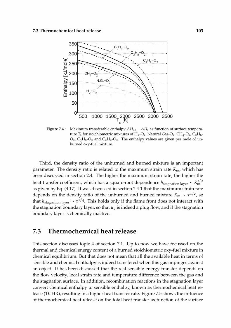
7.3 Thermochemical heat release 103
500 1000 1500 2000 2500 3000 35000
50
100
150
200
250
300
350
Ts [K]
Ent
halp
y [k
J/m
ole]
H2−O
2
N.G.−O2
CH4−O
2
C2H
6−O
2
C3H
8−O
2
C2H
2−O
2
Figure 7.4 Maximum transferable enthalpy ∆ Had ∆ Hs as function of surface tempera-ture Ts for stoichiometric mixtures of H-O, Natural Gas-O, CH-O, CH-O, CH-O and CH-O. The enthalpy values are given per mole of un-burned oxy-fuel mixture.
Third, the density ratio of the unburned and burned mixture is an importantparameter. The density ratio is related to the maximum strain rate Km, which hasbeen discussed in section 2.4. The higher the maximum strain rate, the higher theheat transfer coefficient, which has a square-root dependence hstagnation layer
K/m
as given by Eq. (4.17). It was discussed in section 2.4.1 that the maximum strain ratedepends on the density ratio of the unburned and burned mixture Km
τ/, sothat hstagnation layer
τ/. This holds only if the flame front does not interact withthe stagnation boundary layer, so that u is indeed a plug flow, and if the stagnationboundary layer is chemically inactive.
7.3 Thermochemical heat release
This section discusses topic 4 of section 7.1. Up to now we have focussed on thethermal and chemical energy content of a burned stoichiometric oxy-fuel mixture inchemical equilibrium. But that does not mean that all the available heat in terms ofsensible and chemical enthalpy is indeed transfered when this gas impinges againstan object. It has been discussed that the real sensible energy transfer depends onthe flow velocity, local strain rate and temperature difference between the gas andthe stagnation surface. In addition, recombination reactions in the stagnation layerconvert chemical enthalpy to sensible enthalpy, known as thermochemical heat re-lease (TCHR), resulting in a higher heat transfer rate. Figure 7.5 shows the influenceof thermochemical heat release on the total heat transfer as function of the surface

104 From heat transfer predictions towards burner design
500 1000 1500 2000 2500 30001.5
2
2.5
3
3.5
Ts [K]
a TC
HR
[−]
H2−O
2
C2H
2−O
2
CH4−O
2
C2H
6−O
2
aTCHR
= (qconvective
+ qTCHR
) / qconvective
Figure 7.5 Thermochemical heat release ratio aTCHR as function of surface temperature Tsfor various mixtures: H-O with a s (dotted line), CH-O witha s (solid line), CH-O with a s (dashed-dotted line),and CH-O with a s (dashed line)
temperature in terms of the heat transfer ratio aTCHR, introduced in section 7.1, forvarious oxy-fuel mixtures.
These ratios have been determined by performing stagnation boundary layercomputations as discussed in chapter 5. The main criterium for performing thiskind of calculations is that the burned gas is in chemical equilibrium at the edgeof the stagnation boundary layer. Hence, the flame front does not interact with thestagnation boundary layer. If the burner is placed close enough to the object, sothat the flame tip interacts with the stagnation boundary layer, the gas starts to cooldown even before it reaches chemical equilibrium. In that case, the maximum flametemperature is below the adiabatic flame temperature (T < Tad), and the sensibleenthalpy of the gas at maximum temperature is lower than the sensible enthalpy ofa gas when it would be in chemical equilibrium (∆ Hs
< ∆ Hsad).
If a mixture reaches chemical equilibrium the maximum strain rate relates to theapplied strain rate Km aτ/, with a the applied strain rate. The maximum strainrate is also related to the plug flow velocity of the burned gas u and the distancefrom the flame tip to the target H, with Km
u/H. When the flame tip is faraway from the target or the plug flow velocity u is low, the maximum strain rateand therefore applied strain rate are relatively low. Mixtures of CH-O and CH-O have a relatively low laminar flame speed, and as a result a relatively low plugflow velocity and low strain rate, which is taken equal to a 4000 s . The H-O
mixture has a high flame speed but somewhat lower density ratio and as a resulta somewhat higher plug flow velocity. The applied strain rate is then somewhat

7.3 Thermochemical heat release 105
1 2 3 4 5 6x 10
4
1.5
1.6
1.7
1.8
1.9
2
Km
[1/s]
a TC
HR
[−]
aTCHR
= (qconvective
+ qTCHR
) / qconvective
Figure 7.6 Thermochemical heat release factor aTCHR as function of maximum strain rateKm for a CH-O mixture impinging against a wall at 700 K.
higher and taken equal to a 6000 s . The CH-O has both a high flame speedand a high density ratio, so that the applied strain rate is much higher and takenequal to a 16000 s . However, these strain rates are typically low strain rates forall mixtures, and all mixtures can be considered in chemical equilibrium.
The heat transfer ratio aTCHR is approximately 2 for low stagnation plane temper-atures for all mixtures. For increasing stagnation plane temperature aTCHR increasesfor mixtures of H-O, CH-O and CH-O, but decreases for CH-O-mixtures.Furthermore, Fig. 7.5 shows that for low stagnation plane temperatures, aTCHR in-creases with increasing C/H-ratio, while for high stagnation plane temperatures,aTCHR increases with decreasing C/H-ratio. Recombination reactions of species withcarbon atoms are important at low temperatures while the recombination reactionsof species with hydrogen atoms are important at high temperatures.
The more recombination reactions take place, the more chemical heat is releasedand the higher the heat transfer rate. In principle, like discussed in chapter 4, themaximum heat release is achieved if recombination is maximum and the stagnationboundary layer is in local chemical equilibrium. For a higher strain rate the timeavailable for recombination decreases. Therefore, a higher flow velocity, or strainrate, results in a lower amount of recombination reactions and in a lower thermo-chemical heat release. However, due to the increased velocity, the transport of rad-icals towards the stagnation layer is increased. As a result, the ratio aTCHR is onlyslightly dependent on the strain rate, as is indicated in Fig. 7.6 for a CH-O-mixtureand has been shown in section 4.6 for hydrogen mixtures.
With all this information we can estimate the total heat transfer once the burner
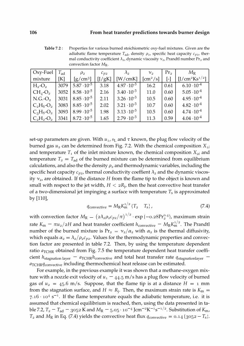
106 From heat transfer predictions towards burner design
Table 7.2 Properties for various burned stoichiometric oxy-fuel mixtures. Given are theadiabatic flame temperature Tad, density ρ, specific heat capacity cp, ther-mal conductivity coefficient λ, dynamic viscosity ν, Prandtl number Pr andconvection factor MR.
Oxy-Fuel Tad ρ cp λ ν Pr MR
mixture [K] [g/cm] [J/gK] [W/cmK] [cm/s] [-] [J/cmKs/]H-O 3079 5.87 ·10-5 3.18 4.97 ·10-3 16.2 0.61 6.10 ·10-4
CH-O 3052 8.58 ·10-5 2.16 3.40 ·10-3 11.0 0.60 5.05 ·10-4
N.G.-O 3031 8.85 ·10-5 2.11 3.26 ·10-3 10.5 0.60 4.95 ·10-4
CH-O 3083 8.85 ·10-5 2.02 3.21 ·10-3 10.7 0.60 4.82 ·10-4
CH-O 3093 8.99 ·10-5 1.98 3.13 ·10-3 10.5 0.60 4.74 ·10-4
CH-O 3341 8.72 ·10-5 1.65 2.79 ·10-3 11.3 0.59 4.04 ·10-4
set-up parameters are given. With u, sL and τ known, the plug flow velocity of theburned gas u can be determined from Fig. 7.2. With the chemical composition Xiand temperature T of the inlet mixture known, the chemical composition Xi andtemperature T Tad of the burned mixture can be determined from equilibriumcalculations, and also the the density ρ and thermodynamic variables, including thespecific heat capacity cp, thermal conductivity coeffient λ and the dynamic viscos-ity ν, are obtained. If the distance H from the flame tip to the object is known andsmall with respect to the jet width, H < Rj, then the heat convective heat transferof a two-dimensional jet impinging a surface with temperature Ts is approximatedby [110],
qconvective MRK/mT Ts , (7.4)
with convection factor MR (
λρcp/π)/ · exp
.Pr. , maximum strain
rate Km πu/H and heat transfer coefficient hconvective MRK/m . The Prandtl
number of the burned mixture is Pr ν/α with α is the thermal diffusivity,which equals α λ/ρcp. Values for the thermodynamic properties and convec-tion factor are presented in table 7.2. Then, by using the temperature dependentratio aTCHR obtained from Fig. 7.5 the temperature dependent heat transfer coeffi-cient hstagnation layer aTCHRhconvective and total heat transfer rate qstagnationlayer aTCHRqconvective including thermochemical heat release can be estimated.
For example, in the previous example it was shown that a methane-oxygen mix-ture with a nozzle exit velocity of u . m/s has a plug flow velocity of burnedgas of u . m/s. Suppose, that the flame tip is at a distance H mmfrom the stagnation surface, and H ≈ Rj. Then, the maximum strain rate is Km . · s . If the flame temperature equals the adiabatic temperature, i.e. it isassumed that chemical equilibrium is reached, then, using the data presented in ta-ble 7.2, T Tad K and MR . · Jcm K s /. Substitution of Km,T and MR in Eq. (7.4) yields the convective heat flux qconvective .
Ts .
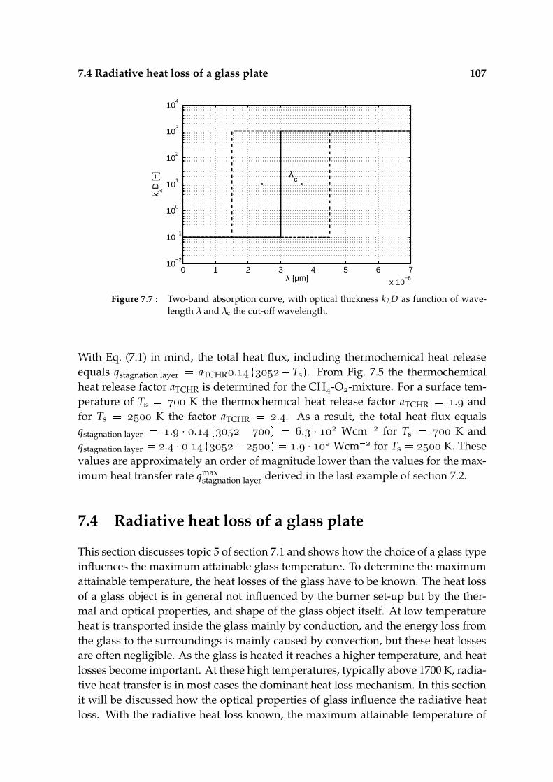
7.4 Radiative heat loss of a glass plate 107
0 1 2 3 4 5 6 7
x 10−6
10−2
10−1
100
101
102
103
104
λ [µm]
k λD [−
] λc
Figure 7.7 Two-band absorption curve, with optical thickness kλD as function of wave-length λ and λc the cut-off wavelength.
With Eq. (7.1) in mind, the total heat flux, including thermochemical heat releaseequals qstagnation layer aTCHR.
Ts . From Fig. 7.5 the thermochemical
heat release factor aTCHR is determined for the CH-O-mixture. For a surface tem-perature of Ts K the thermochemical heat release factor aTCHR . andfor Ts K the factor aTCHR .. As a result, the total heat flux equalsqstagnation layer . · .
. · Wcm for Ts K and
qstagnation layer . · . . · Wcm for Ts K. These
values are approximately an order of magnitude lower than the values for the max-imum heat transfer rate qmax
stagnation layer derived in the last example of section 7.2.
7.4 Radiative heat loss of a glass plate
This section discusses topic 5 of section 7.1 and shows how the choice of a glass typeinfluences the maximum attainable glass temperature. To determine the maximumattainable temperature, the heat losses of the glass have to be known. The heat lossof a glass object is in general not influenced by the burner set-up but by the ther-mal and optical properties, and shape of the glass object itself. At low temperatureheat is transported inside the glass mainly by conduction, and the energy loss fromthe glass to the surroundings is mainly caused by convection, but these heat lossesare often negligible. As the glass is heated it reaches a higher temperature, and heatlosses become important. At these high temperatures, typically above 1700 K, radia-tive heat transfer is in most cases the dominant heat loss mechanism. In this sectionit will be discussed how the optical properties of glass influence the radiative heatloss. With the radiative heat loss known, the maximum attainable temperature of

108 From heat transfer predictions towards burner design
1500 2000 2500 300010
3
104
105
106
107
T [K]
e [W
/m2 ]
λc
eb
20
15
10
5
4
3
2
1
7
qstagnation layer
2
qstagnation layer
Figure 7.8 Hemispherical emissive power for a semi-transparent plate with a non-emissive spectral band for λ < λc and an emissive band for λ > λc. Surfaceheat losses as function of surface temperature are given for λc 1, 2, 3, 4, 5,7, 10, 15 and 20 µm (solid lines). Also the blackbody emission eb is presented(dashed line), and qstagnation layer is a typical heat flux of an impinging flame tothe plate (dashed-dotted lines).
an isothermal glass plate is estimated. In section 3.1 the optical and thermodynamicproperties of glass are outlined. A typical glass is a semi-transparant material; it isapproximately transparent within some region of the optical spectrum, while it isabsorbing within another region of the spectrum, and the transparancy is indicatedby the optical thickness, presented in section 3.2.2. For reasons of simplicity, it isassumed in this section that that the optical spectrum of the glass consists of twospectral bands with one transparent band for short wavelengths and one absorb-ing band for long wavelengths, as represented in Fig. 7.7. The boundary betweenthe absorbing and transparent band is given by the cut-off wavelength λc. To de-termine the optical thickness for every part of the spectrum, the spectrally selectiveabsorption coefficient kλ is multiplied with the typical length, in our case the thick-ness of the plate D which is of the order of 1 mm. Then the optical thickness forthe lower region of the spectrum (λ < λc) is kλD , and the plate can be consid-ered transparent for this region of the spectrum. The optical thickness for the upperpart (λ > λc) is kλc D , and the plate can be considered absorbing or opaque forthis region of the spectrum. The radiative heat loss by the transparent band is verysmall and will be neglected. The radiative heat loss by the absorbing band will bemaximized: the plate is considered to behave as a blackbody for this region of thespectrum.
The radiative energy that is emitted by one of the plate surfaces, is then equal to
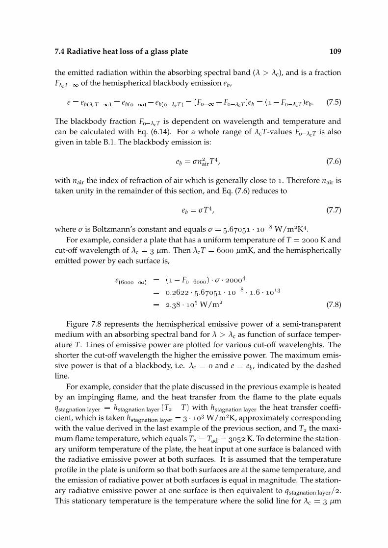
7.4 Radiative heat loss of a glass plate 109
the emitted radiation within the absorbing spectral band (λ > λc), and is a fractionFλcT of the hemispherical blackbody emission eb,
e ebλcT eb
eb
λcT
F F λcT eb
F λcT eb. (7.5)
The blackbody fraction F λcT is dependent on wavelength and temperature andcan be calculated with Eq. (6.14). For a whole range of λcT-values F λcT is alsogiven in table B.1. The blackbody emission is:
eb σnairT, (7.6)
with nair the index of refraction of air which is generally close to . Therefore nair istaken unity in the remainder of this section, and Eq. (7.6) reduces to
eb σT, (7.7)
where σ is Boltzmann’s constant and equals σ . · W/mK.For example, consider a plate that has a uniform temperature of T K and
cut-off wavelength of λc µm. Then λcT µmK, and the hemisphericallyemitted power by each surface is,
e
F ·σ ·
. · . · · . ·
. · W/m (7.8)
Figure 7.8 represents the hemispherical emissive power of a semi-transparentmedium with an absorbing spectral band for λ > λc as function of surface temper-ature T. Lines of emissive power are plotted for various cut-off wavelenghts. Theshorter the cut-off wavelength the higher the emissive power. The maximum emis-sive power is that of a blackbody, i.e. λc and e eb, indicated by the dashedline.
For example, consider that the plate discussed in the previous example is heatedby an impinging flame, and the heat transfer from the flame to the plate equalsqstagnation layer hstagnation layer
T T with hstagnation layer the heat transfer coeffi-
cient, which is taken hstagnation layer · W/mK, approximately correspondingwith the value derived in the last example of the previous section, and T the maxi-mum flame temperature, which equals T Tad K. To determine the station-ary uniform temperature of the plate, the heat input at one surface is balanced withthe radiative emissive power at both surfaces. It is assumed that the temperatureprofile in the plate is uniform so that both surfaces are at the same temperature, andthe emission of radiative power at both surfaces is equal in magnitude. The station-ary radiative emissive power at one surface is then equivalent to qstagnation layer/.This stationary temperature is the temperature where the solid line for λc µm
110 From heat transfer predictions towards burner design
intersects with the dashed-dotted line of qstagnation layer/, and this occurs at a tem-perature of appoximately T K. This temperature is the maximum attainabletemperature.
Many engineering computations make use of an emission coeffient ε with,
e εeb. (7.9)
If it is assumed that the glass consists of a number of spectral bands for which theglass is fully absorbing, or opaque, then with Eq. (7.5) ε is estimated by,
ε
j jopaque
[
F λ
j T F λ j T
]
(7.10)
with j jopaque the indices of the opaque spectral bands (λ j < λ < λ j ). Note that
the emission coefficient is now dependent on temperature. The expression for ε isonly accurate when,
1. the spectral domain is clearly divisible in spectral bands which, with the ge-ometry taken into account, can each be considered as either transparant orabsorbing,
2. the temperature in the plate is uniform.
Especially the non-uniformity of the temperature profile in the plate may lead tosignificant inaccuracies. In the production process this is often the case. The glass isheated by a flame impinging against one surface. As a result the temperature nearthis surface increases rapidly. However, conductive heat transfer in a glass is gen-erally slow. As a result, the temperature near the opposite surface falls behind, andthe temperature profile becomes non-uniform. Since radiation has a fourth-powerdependence of the temperature the emission of radiative heat inside the plate be-comes very asymmetric. The majority of the radiation is emitted in the hot region ofthe plate. Part of this radiation might be reabsorbed elsewhere in the plate, leadingto redistribution of radiative energy. Another part is lost to the environment. As aresult, if the radiative heat loss has to be determined accurately, radiative transfershould be considered locally and detailed computations have to be performed in or-der to determine the radiative heat fluxes. This topic was treated more extensivelyin section 6.3.3. When it is assumed that the radiative heat loss of the relatively coldsurface can be neglected compared to the relatively hot wall, an estimate for themaximum attainable temperature can be derived as well.
For example, let us take again the situation of the previous example. However,now it is assumed that the radiative heat loss of the cold surface is neglected. Thestationary radiative emissive power from the hot surface balances with the heat in-put qstagnation layer. The maximum attainable temperature of this surface is the tem-perature where the solid line for λc µm intersects with the dashed-dotted lineof qstagnation layer, and this occurs at a temperature of appoximately T K.
Chapter8General conclusions
In order to optimize the heat transfer of impinging oxy-fuel flames to (quartz)-glassproducts, scientific knowledge has to be gained on the physical and chemical phe-nomena that influence the heat transfer rate. These phenomena include stagnationflow characteristics, chemistry in the flame front, chemistry in the stagnation bound-ary layer, and radiation. The main objective of the research is to investigate the im-portance of the different heat transfer phenomena on the total heat transfer process,and see how each phenomenon is affected by physical parameters, like temperatureor mixture composition. This is done by a one-dimensional fundamental numericalresearch.
Different regions can be identified. The main regions are the flame front, stag-nation boundary layer and glass plate. Heating time scales have been identified forthe flame front, the stagnation boundary layer and the glass plate. The time scaleof the flame front is approximately an order of magnitude smaller than the heatingtime scale of the stagnation boundary layer, which in its turn is orders of magni-tude smaller than the heating time scale of the plate. As a result, the temperatureprofile of the stagnation layer adapts almost instantly to the surface temperature,and the heat flux from the gas to the plate only depends on the stagnation planetemperature. Then, the reacting stagnation flow and plate are only coupled by thestagnation plane temperature, and therefore can be treated seperately, as has beendone troughout the thesis.
8.1 Chemically reacting stagnation flow
Stoichiometric oxy-fuel and air-fuel flames have been studied. The flame speedsand temperatures have been determined with various complex chemistry models.From the calculations it is shown that, depending on the chemical kinetic mecha-nism used, the hydrogen-oxygen flames have adiabatic flame temperatures rang-ing from 3075-3079 K, and laminar flame speeds ranging from 963-1001 cm/s. Thehydrogen-air flames have adiabatic flame temperatures ranging from 2386-2390 K,and laminar flame speeds ranging from 201-259 cm/s. Adiabatic free flame compu-tations with extensive mechanisms have been performed to calculate the adiabaticflame temperatures and flame speeds for different mixtures, and this showed thatoxy-fuel mixtures with methane, propane, and butane as fuel gas have comparable
112 General conclusions
flame temperatures and laminar burning velocities. An acetylene-oxygen mixturehas a much higher flame temperature and laminar burning velocity.
Dissociated species in the burned gas cool down in the stagnation boundarylayer and may recombine exothermally into thermodynamically preferred stableproducts, releasing heat and boosting the heat transfer. This effect is known asthermochemical heat release. The chemical reactions in the flame front can be de-coupled from the recombination reactions in the stagnation boundary layer if theburned mixture reaches chemical equilibrium before it enters the stagnation bound-ary layer. Then the stagnation layer computations can be performed using a mix-ture in chemical equilibrium. It was shown that these equilibrium mixtures consistof relatively small species and a relatively compact chemical kinetic mechanism canbe used for the stagnation layer computations. For the considered oxy-fuel flames,it was shown that thermochemical heat release may increase the heat transfer ratewith 50-150%.
It has been shown that the strain rate is also a key parameter for the heatingprocess, and that the heat transfer rate of an inert stagnating flow has a square-rootdependence of the strain rate. Also the heat transfer rate of a reacting stagnationflame shows a square-root dependence of the strain rate for low strain rates. Forthese strain rates, the burned mixture reaches chemical equilibrium once it leavesthe flame front, but before it enters the stagnation boundary layer. For increasingstrain rate the flame front and stagnation boundary layer start to interact. Chemi-cal equilibrium is not reached, and the maximum flame temperature decreases, dueto the fact that the flame cools down before chemical equilibrium is reached. Thenthe heat transfer rate deviates from the square-root dependence. An approximateexpression has been derived for the critical strain rate at which the flame and stag-nation boundary layer interact. Only for the relatively hot and fast acetylene-oxygenflame this critical strain rate was overpredicted.
The influence of surface chemistry on the heat transfer rate has been studied.By assuming that the plate has identical surface properties as a platinum surface,surface chemistry can influence the heat transfer slightly, enhancing the heat transferup to approximately 10%.
8.2 Heat transfer in a glass object
Heat transfer problems in glasses and many other materials are almost always com-bined conduction-radiation problems. Radiative heat transfer has been calculatedusing the finite volume method, in which the energy equation is written in terms ofenergy fluxes. The radiative energy fluxes have been determined with the discretetransfer method, in which the radiative transfer equation is solved in its integralform. The optical properties of a glass have a strong spectral dependence. Therefore,the radiative transfer equation was solved for a non-scattering material with band-
8.3 From heat transfer predictions to burner design 113
like absorption characteristics. A nearly analytical solution of the radiative transferequation in integral form was found using a stepwise (zeroth-order) temperatureprofile, and a continuous (first-order) temperature profile for a spectral band of ar-bitrary spectral width and a uniform absorption coefficient. The solution methodshave been tested on a one-dimensional conduction-radiation problem. It was con-cluded that the relative error of the radiation fluxes calculated with the zeroth-ordermethod is small for optically thin spectral bands, and increases rapidly for increas-ing optical thickness. It was shown that when the temperature gradients are largeand the radiative heat flux is large compared to the conductive heat flux, the inaccu-racies of the overall heat fluxes are large. However, with the first-order method theerror of the radiative heat fluxes is small or comparable to the error of the conduc-tive heat fluxes for all optical thicknesses. Consequently, it was shown that althoughcalculation of a single radiative transfer equation with the first-order method is rel-atively expensive compared to the calculation of a radiative transfer equation withthe zeroth-order method, results are orders of magnitude more accurate on a coursegrid with large temperature gradients.
To simulate various glass types and other materials, stationary and transientcooling results of a gray plate with varying optical thickness and a semi-transparentplate with varying cut-off wavelength were studied. In the gray transient coolingcase, a minimum cooling time is observed for optical thicknesses of approximately5. Then, the plate as a whole can be considered optically thick, but the plate is op-tically thin enough that part of the radiation that is emitted in the interior region ofthe plate is not completely reabsorbed within the vicinity of the place of emission.An increasing opacity of the material leads to larger temperature gradients, with amaximum gradient when the material acts as a blackbody. In the semi-transparentcase, with a two-band absorption model with variable cut-off wavelength, no mini-mum cooling time is observed. However, the bands studied are either optically thinor optically thick and the optical thickness is not of the order of 5.
8.3 From heat transfer predictions to burner design
A set of predictions for burner design has been developed. The predictions dis-cussed in this thesis should be implemented together with predictions regardingconvective heat transfer of the stagnation flow, which will be discussed in the the-sis of M.J. Remie. It was shown how the fuel gas choice influences the tempera-ture, chemical composition and flow velocity of the burned gas. Furthermore, theaddition of thermochemical heat release in the stagnation boundary layer on theconvective heat transfer was given by means of a multiplication factor for variousfuel gases. Finally, it was shown how the optical properties of glass can be simpli-fied such that the radiative heat loss can be calculated and the maximum attainabletemperature can be estimated.

114 General conclusions

AppendixAGamma-functions
An expression for the definite integral,
u
xm exp
µx dx, (A.1)
was determined by Erdelyi [38] and given in Gradshteyn [48]:
u
xm exp
µx dx
m
µm
[
exp µu
m
l
µu ll
]
µ m γm
, µu u > , Re
µ > , m , , , ... (A.2)
With y µu, the gamma function can be written as [48], [39],
γm
, y y
exp
t tmdt
m
[
exp y
( m
l
yl
l
)]
m , , , ... . (A.3)
In this paper u S j, and µ ki Bn. The gamma function is used in this formfor y µu > (optically thick medium). However, for ≤ y (opticallythin medium) using the gamma function in this form, introduces numerical errors.Therefore, the gamma function for y is rewritten as,
γm
, y mexp
y
l m
yl
l
m , , , ... . (A.4)
u S j is always positive, but µ ki Bn may be negative for small ki. It can bederived that when µ ν < , Eq. (A.2) becomes,
u
xm exp
µx dx u
xm exp
νx dx
expνu
m
i
m
m i
i
um
νu i
γi
, νu u > , Re
ν > , m , , , ... , (A.5)

116 Gamma-functions
when the substitution x u z is performed and the series
u z m m
m
i
um im i ·
z ii
(A.6)
was implemented. The γ-function in Eq. (A.5) is computed again with Eq. (A.3) or(A.4).

AppendixBTables
B.1 Blackbody fractions
λ · T F λT λ · T F λT λ · T F λT λ · T F λTµmK µmK µmK µmK. .E . . . . . .
. .E . . . . . .
. .E . . . . . .
. .E . . . . . .
. .E . . . . . .
. .E . . . . . .
. .E . . . . . .
. .E . . . . . .
. .E . . . . . .
. .E . . . . . .
. .E . . . . . .
. .E . . . . . .
. .E . . . . . .
. .E . . . . . .
. .E . . . . . .
. .E . . . . . .
. .E . . . . . .
. .E . . . . . .
. .E . . . . . .
. .E . . . . . .
. .E . . . . . .
. .E . . . . . .
. .E . . . . . .
. .E . . . . . .
. .E . . . . . .
. .E . . . . . .
. .E . . . . . .
. .E . . . . . .

118 Tables
λ · T F λT λ · T F λT λ · T F λT λ · T F λTµmK µmK µmK µmK
. . . . . . . .
. . . . . . . .
. . . . . . . .
. . . . . . . .
. . . . . . . .
. . . . . . . .
. . . . . . . .
. . . . . . . .
. . . . . . . .
. . . . . . . .
. . . . . . . .
. . . . . . . .
. . . . . . . .
. . . . . . . .
. . . . . . . .
. . . . . . . .
. . . . . . . .
. . . . . . . .
. . . . . . . .
. . . . . . . .
. . . . . . . .
. . . . . . . .
. . . . . . . .
. . . . . . . .
. . . . . . . .
. . . . . . . .
. . . . . . . .
. . . . . . . .
. . . . . . . .
. . . . . . . .
. . . . . . . .
. . . . . . . .
. . . . . . . .
. . . . . . . .
. . . . . . . .
. . . . . . . .
. . . . . . . .
. . . . . . . .
. . . . . . . .
. . . . . . . .
. . . . . . . .
. . . . . . . .
Bibliography
[1] D. Balsara, Fast and accurate discrete ordinates methods for multidimensionalradiative transfer, Part I. Basic methods, J. Quant. Spectrosc. Radiat. Transfer, 69(2001) 671-707.
[2] N.P. Bansal, R.H. Doremus, Handbook of Glass Properties, Academic Press, Or-lando, Florida (1986).
[3] C.E. Baukal, L.K. Farmer, B. Gebhart, I. Chan, Heat transfer mechanisms in flameimpingement heating, Proc. of the 1995 Int. Gas Res. Confer. (Ed. D.A. Dolec),Gov’t Institutes, Inc., Rockville, MD, 2 (1996) 2277-2287.
[4] C.E. Baukal, B. Gebhart, Surface condition effects on flame impingement heattransfer, Therm. Fluid Sci. 15 (1997) 323-3335.
[5] C.E. Baukal, B. Gebhart, A review of semi-analytical solutions for flame inpingementheat transfer, Int. J. Heat Mass Transfer, 39(14) (1996) 2989-3002.
[6] C.E. Baukal, Oxygen-Enhanced Combustion, CRC Press LLC, Boca Raton, (1998).
[7] C.E. Baukal, Heat Transfer in Industrial Combustion, CRC Press LLC, Danvers,Massachussetts, (2000).
[8] J.M. Beer, N.A. Chigier, Impinging jet flames, Combust. Flame 12 (1968) 575-586.
[9] T. Berg, Laser Diagnostic Investigation on Heat Transfer from Burners to QuartzProducts, University of Bielefeld, Bielefeld, (2000).
[10] H. Bongers, Analysis of Flamelet-Based Methods to Reduce Chemical Kinetics inFlame Computations, PhD-thesis, Technische Universiteit Eindhoven, (2005).
[11] K.J. Bosschaart, Analysis of the Heat Flux Method for Measuring Burning Velocities,PhD-thesis, Technische Universiteit Eindhoven, (2002).
[12] P.H. Bouma, Methane-Air Combustion on Ceramic Foam Surface Burners, PhD-thesis, Technische Universiteit Eindhoven, (1997).
[13] F.P. Boynton, C.B. Ludwig, Total emissivity of hot water vapor–II. semi-empirical charts deduced from long-path spectral data, Int. J. Heat Mass Transfer14 (1971) 963-973.
120 Bibliography
[14] J. Buckmaster, The Mathematics of Combustion, Society for Industrial and Ap-plied Mathematics, Philadelphia (1985).
[15] J.C. Chai, One-dimensional transient radiation heat transfer modeling using afinite-volume method, Numer. Heat Transfer, Part B: Fundamentals 44 (2003) 187-208.
[16] J.C. Chai, H.S. Lee, S.V. Patankar, Improved treatment of scattering using thediscrete ordinates method, J. Heat Transfer 116 (1994) 260.
[17] J.C. Chai, S.V. Patankar, Finite-volume method for radiative heat transfer, Ad-vances in Numer. Heat Transfer, 2 (2000) 109-138.
[18] S. Chandrasekhar, Radiative Transfer, Dover Publications Inc., New York, (1960).
[19] CHEM1D, A one-dimensional laminar flame code, Eindhoven University of Tech-nology, http://www.combustion.tue.nl
[20] I. Chorkendorff, J.W. Niemantsverdriet, Concepts of Modern Catalysis and Kinet-ics, WILEY-VCH Verlag GmbH & Co. KGaA, Weinheim, (2003).
[21] E.H. Chui, G.D. Raithby, Computation of radiant heat transfer on a non-orthogonal mesh using the finite-volume method, Numer. Heat Transfer, Part B:Fundamentals 22 (1993) 269-288.
[22] M.E. Coltrin, R.J. Kee, F.M. Rupley, E.M. Meeks, Surface Chemkin-III: A FortranPackage for Analysing Heterogeneous Chemical Kinetics at a Solid-Surface - Gas-PhaseInterface. Sandia Report SAND96-8217, Sandia National Laboratories, (1996).
[23] R. Conolly, R.M. Davies, A study of convective heat transfer from flames, Int. J.Heat Mass Transfer 15 (1972) 2155-2172.
[24] R.A. Cookson, J.K. Kilham, Energy transfer from hydrogen-oxygen Flames,Proc. Ninth Intern. Symp. Combust. Academic Press, New York (1963) 257-263.
[25] Corning Glass Works: Bulletin B-83, Properties of Selected Commercial Glasses,Corning, New York (1957).
[26] P.J. Coelho, Bounded skew high-order resolution schemes for the discrete ordi-nates method, J. Comput. Phys. 175 (2002) 412-437.
[27] M.F.G. Cremers, M.J. Remie, K.R.A.M. Schreel, L.P.H. de Goey, Heat transfermechanisms of laminar hydrogen + oxygen flames, Combust. Flame, 139(1-2)(2004) 39-51.
[28] M.F.G. Cremers, M.J. Remie, K.R.A.M. Schreel, L.P.H. de Goey, Solution of theintegrated radiative transfer equation for gray and non-gray media, J. Num. HeatTransfer: Part A: Applications, (Accepted for publication).
121
[29] M.F.G. Cremers, M.J. Remie, K.R.A.M. Schreel, L.P.H. de Goey, Thermochemi-cal heat release of laminar stagnation flames of fuel and oxygen, Proc. Comb. Inst.(2006) submitted
[30] A.L. Crosbie, R. Viskanta, The exact solution to a simple nongray radiativetransfer problem, J. Quant. Spectrosc. Radiat. Transfer, 9 (1969) 553-568.
[31] A.L. Crosbie, R. Viskanta, Nongray radiative transfer in a planar medium ex-posed to a collimated flux, J. Quant. Spectrosc. Radiat. Transfer 10 (1970) 465-485.
[32] P.S. Cumber, Improvements to the discrete transfer method of calculating ra-diative transfer, Int. J. Heat Mass Transfer 39(12) (1995) 2251-2258.
[33] D.R. Davies, Heat Transfer from Working Flame Burners, B.S. Thesis, University ofSalford, Salford, United Kingdom (1979).
[34] A.H. Dent, A. Patel, J. Gutleber, E. Tormey, S. Sampath, H. Herman, MaterialsScience and Engineering: B 87 (1) (2001) 23-30.
[35] G. Dixon-Lewis, Flame structure and flame reaction kinetics II. Transport phe-nomena in multicomponent systems, Proc. Roy. Soc., A, 307 (1968) 111-135.
[36] D.G. Doornink, R.G. Hering, Transient radiative heat transfer in a non-graymedium, J. Quant. Spectrosc. Radiat. Transfer, 12 (1972) 1161-1174.
[37] D.G. Doornink, R.G. Hering, Simultaneous radiative and conductive heattransfer in non-gray media, J. Quant. Spectrosc. Radiat. Transfer, 13 (1973) 323-332.
[38] A. Erdelyi et al., Tables of Integral Transforms, I, pp. 134, McGraw Hill, New York,(1954).
[39] A. Erdelyi et al., Higher Transcendental Functions, II, pp. 133-136, McGraw Hill,New York, (1953-1955).
[40] A. Ern, V.Giovangigli. Eglib Server with User’s Manual,http:/blanche.polytechnique.fr/www.eglib (1996).
[41] A. Ern, V. Giovangigli, EGlib: a General-Purpose FORTRAN Library for Mul-ticomponent Transport Property Evaluation, CERMICS, ENPC and Centre deMathematiques Appliquees, CNRS, 2000.
[42] H. Farhat, M.S. Radhouani, Etude tridimensionelle du transfert radiatif dansun milieu semi-transparant diffusant anisotrope par la methode des transfertdiscrets modifiee, Rev. Gen Therm 36 (1997) 330-344.
[43] L.M. Farrell, T.T. Pavlack, L. Rich, Iron and Steel Eng. 72 (3) (1995) 35-42.
122 Bibliography
[44] J.A. Fay, F.R. Ridell, Theory of stagnation point heat transfer in dissociated air,J. Aero Sci. 25 (1958) 73-85.
[45] W.A. Fiveland, A Discrete Ordinates Method for Predicting Radiative Heat Transferin Axisymmetric Enclosures, ASME Paper 82-HT-20 (1982).
[46] R. Gardon, Calculation of temperature distribution in glass plates undergoingheat treatment, J. Am. Ceramic Soc. 41 (1958) 200.
[47] W.H. Giedt, L.L. Cobb, E.J. Russ, Effect of Hydrogen Recombination on TurbulentFlow Heat Transfer, ASME Paper 60-WA-256, New York (1960).
[48] I.S. Gradshteyn, I.M. Ryzhik, Table of Integrals, Series, and Products, Alan Jeffrey(editor), 5th ed., Academic Press, London, translated from Russian by ScriptaTechnica, Inc., (1994).
[49] G.R.A. Groot, Modelling of Propagating Spherical and Cylindrical Premixed Flames,PhD-thesis, Technische Universiteit Eindhoven, 2003.
[50] G.K. Hargrave, J.K. Kilham, The effect of turbulence intensity on convectiveheat transfer from premixed methane-air flames, Instn Chem. Engng. Symp. Ser.2(86) (1984) 1025-1034.
[51] B. Hellsing, B. Kasemo, V.P. Zhdanov, Kinetics of the hydrogen-oxygen reactionon platinum, J. Catal. 132 (1991) 210-228.
[52] A.O. Hemeson, M.E. Horsley, M.R.I. Purvis, A.S. Tariq, Heat transfer fromflames to convex surfaces, Instn Chem. Engng. Symp. Ser. 2(86) (1984) 969-978.
[53] J.O. Hirschfelder, C.F. Curtiss, Flame propagation in explosive gas mixtures,Proc. Combust. Instit. 3 (1949) 121-127
[54] J.O. Hirschfelder, C.F. Curtiss, R.B. Bird, Molecular Theory of Gases and Liquids,Wiley, New York, (1954).
[55] C.J. Hoogendoorn, C.O. Popiel, T.H. van der Meer, Turbulent heat transfer ona plane surface in impingement round premixed flame jets Proc. of the Sixth Int.Heat Transfer Conf. Toronto, 4 (1978) 107-112.
[56] M.E. Horsley, M.R.I. Purvis, A.S. Tariq, Convective heat transfer from lami-nar and turbulent premixed flames, Heat Transfer (Eds. U. Grigull, E. Hahne,K. Stephan, J. Straub) 3, Hemisphere, Washington (1982) 409-415.
[57] L.H. Howell, R.B. Pember, P.Colella, J.P. Jessee, W.A. Fiveland, A conservativeadaptive mesh Aagorithm for unsteady combined mode heat transfer using thediscrete ordinate method. Numer. Heat Transfer, Bart B: Fundamentals 35 (1999)407-430.
123
[58] C.K. Hsieh, K.C. Su, Thermal radiative properties of glass from 0.32 to 206 µm,Solar Energy 22 (1979) 37-43.
[59] H. Ikeda, F.A. Libby, P.A. Sato, J. Williams, Catalytic combustion of hydrogen-air mixtures in stagnation flows, Combust. Flame 93 (1993) 138-148.
[60] H. Ikeda, J. Sato, B. Williams,Surface kinetics for catalytic combustion ofhydrogen-air mixtures on platinum at atmospheric pressure in stagnation flows,Surf. Science 326 (1995) 11-26.
[61] F.P. Incropera, Liquid Cooling of Electronic Devices by Single-Phase Convection, Wi-ley, New York (1999).
[62] F.P. Incropera, D.P. DeWitt, Fundamentals of Heat and Mass Transfer, 4th ed., Wi-ley, New York (1996).
[63] K.A.R. Ismail, C.S. Salinas, Application of multidimensional scheme and thediscrete ordinate method to radiative heat transfer in a two-dimensional enclo-sure with diffusely emitting and reflecting boundary walls, J. Quant. Spectrosc.Radiat. Transfer 88 (2004) 407-422.
[64] A. Ivernel, P. Vernotte, Etude experimentale de l’amelioration des transfert con-vectis dans les fours par suroxygenation du comburant, Rev. Gen. Therm., Fr.210-211 (1979) 375-391.
[65] E.G. Jackson, J.K. Kilham, Heat transfer from combustion products by forcedconvection, Ind. Engng. Chem. 48(11) (1956) 2077-2079.
[66] W.M. Kays, M.E. Crawford, Convective Heat and Mass Transfer, p.141, 2nd ed.,McGraw-Hill, New York (1980).
[67] R.J. Kee, G. Dixon-Lewis, J. Warnatz, M.E. Coltrin, J.A. Miller, A Fortran Com-puter Code Package for the Evaluation of the Gas-Phase Multicomponent TransportProperties. Sandia Report SAND86-8246, Sandia National Laboratories, (1986).
[68] R.J. Kee, F.M. Rumpley, J.A. Miller, CHEMKIN-II: A Fortran Chemical KineticsPackage for the Analysis of Gas-Phase Kinetics. Technical Report SAND89-8009,Sandia National Laboratories, (1989).
[69] K.K. Kelley, Contributions to the data on theoretical metallurgy, XI, entropiesof inorganic substances U.S. Bur. Mines Bull. 477 (1950).
[70] J.K. Kilham, Energy transfer from flame gases to solids, Third Symp. on Combust.and Flame and Explosion Phenomena Williams
Wilkins, Baltimore, MD, (1949)
733-740.
124 Bibliography
[71] J.K. Kilham, P.G. Dunham, Energy transfer from carbon monoxide flames,Eleventh Symp. (Intern.) on Combust. The Combust. Instit., Pittsburg, PA, (1967)899-905.
[72] J.K. Kilham, M.R.I. Purvis, Heat transfer from hydrocarbon-oxygen flames,Proc. of the Eleventh Int. Symp. on Combust. The Combustion Institute, Pittsburg,PA (1967).
[73] J.K. Kilham, M.R.I. Purvis, Heat transfer from normally impinging flames,Comb. Sci. Techn. 18 (1978) 81-90.
[74] S.H. Kim, K.Y. Huh, Assessment of the finite-volume method and the discreteordinate method for radiative heat transfer in a three-dimensional rectangularenclosure, Numer. Heat Transfer, Part B: Fundamentals, 35(1) (1999) 85-112.
[75] R. Koch, R. Becker, Evaluation of quadrature schemes for the discrete ordinatesmethod, J. Quant. Spectrosc. Radiat. Transfer, 84 (2004) 423-435.
[76] H.-C. Kung, M. Sibulkin, Radiative transfer in a nongray gas between parallelwalls, J. Quant. Spectrosc. Radiat. Transfer 9 (1969) 1447-1461.
[77] K.K. Kuo, Principles of Combustion, 2nd ed., John Wiley
Sons, Inc., Hoboken,New Jersey (2005).
[78] K.D. Lathrop, B.G. Carlson, Discrete Ordinates Angular Quadrature of NeutronTransport Equation, Technical Report, LA-3186, Los Alamos Scientific Laboratory,Los Alamos, New Mexico (1965).
[79] K.H. Lee, R. Viskanta, Two-dimensional combined conduction and radiationheat transfer: Comparison of the discrete ordinates method and the diffusionapproximation methods, Numer. Heat Transfer, Part A: Applications, 39(3) (2001)205-225.
[80] B. van Leer, Towards the ultimate conservative difference scheme. II. Mono-tonicity and conservation combined in a second order scheme, J. Comput. Phys.14 (1974) 361-370.
[81] B. Lewis, G. von Elbe, Combustion, Flames, and Explosions of Gases, AcademicPress, London (1961).
[82] F.C. Lockwood, N.G. Shah, A new radiation solution method for incorpora-tion in general combustion prediction procedures, Proc. Eighteenth Symp. (Int) onCombustion, The Combustion Institute (1981) 1405-1414.
[83] C.B. Ludwig, W. Malkmus, J.E. Reardon, J.A.L. Thomson, Handbook of InfraredRadiation from Combustion Gases, NASA SP-3080, (1973).
125
[84] F.A. Lammers, Ceramic-Foam Surface Burners in High-Temperature Environments,PhD-thesis, Technische Universiteit Eindhoven (2001).
[85] B.J. van der Linden, Radiative Heat Transfer in Glass: The Algebraic Ray TraceMethod, PhD-thesis, Technische Universiteit Eindhoven (2002).
[86] U. Maas, J. Warnatz, Ignition processes in hydrogen—oxygen mixtures Com-bust. Flame 74 (1988) 53-69.
[87] G.K. Malikov, D.L. Lobanov, K.Y. Malikov, V.G. Lisienko, R. Viskanta,A.G. Federov, Direct flame impingement heating for rapid thermal materialsprocessing Int. J. Heat and Mass Transfer 44 (2001) 1751-1758.
[88] N. Marinov, C.K. Westbrook, W.J. Pitz, in: S.H. Chan (Ed), Transport Phenomenain Combustion 1, Taylor and Francis, Washington, DC (1996).
[89] N.M. Marinov, W.J. Pitz, C.K. Westbrook, A.M. Vincitore, M.J. Castaldi,S.M. Senkan, Aromatic and Polycyclic Aromatic Hydrocarbon Formation in aLaminar Premixed n-Butane Flame, Combust Flame 114 (1998) 192-213.
[90] S. Marthur, P.K. Tondon, S.C. Saxena, Thermal conductivity of binary, ternaryand quaternary mixtures of rare gases, Mol. Phys., 12 (1967) 569.
[91] H. Martin, in: J.P.Hartnett, T.F.Irvine, Jr. (Eds.), Advances in Heat Transfer 13,Academic Press, New York (1977).
[92] J.D. Mellado, M. Kindelan, A.L. Sanchez, A simplified formulation for het-erogeneous catalytic combustion in stagnation-point flows Combust. and Flame132(3) (2003) 596-599.
[93] T.H. van der Meer, Heat Transfer from Impinging Flame Jets, Ph.D. Thesis, Techni-cal University of Delft, The Netherlands (1987).
[94] T.H. van der Meer, Stagnation point heat transfer from turbulent low Reynoldsnumber jets and flame jets, Exper. Therm. Fluid Sci. 4 (1991) 115-126.
[95] A. Milson, N.A. Chigier, Studies of methane-air flames impinging on a coldplate, Combust. Flame 21 (1973) 295-305.
[96] M.F. Modest, Radiative Heat Transfer, 2nd ed., Academic Press, Elsevier Science,San Diego, (2003).
[97] A.V. Mokhov, A.P. Nefedov, B.V. Rogov, V.A. Sinel’shchikov, A.D. Usachev, A.V.Zobnin, H.B. Levinsky, CO behavior in laminar boundary layer of combustionproduct flow, Combust. Flame 119(1-2) (1999) 161-173.
[98] H. Motz, H. Wise, Diffusion and heterogeneous reaction, III, atom recombina-tion at a catalytic boundary, J. Chem. Phys. 32 (1960) 1893-1894.
126 Bibliography
[99] J.B. Murdoch, Illumination Engineering; From Edison’s Lamp to the Laser, Macmil-lan Publishing Company, New York, (1985).
[100] S. Nawaz, Heat Transfer from Oxygen Enriched Methane Flames, Ph.D. Thesis,The University of Leeds, Leeds, United Kingdom (1973).
[101] J.A. van Oijen, Flamelet-Generated Manifolds: Development and Application to Pre-mixed Laminar Flames, PhD-thesis, Technische Universiteit Eindhoven (2002).
[102] M. Okkerse, Numerical Simulation of an Oxy-Acetylene Torch Reactor for DiamondCVD, PhD-thesis, Technische Universiteit Delft (2000).
[103] W. Potze, Radiation heat transfer in aximsymmetric quartz glass tubes, J.Quant. Spectrosc. Radiat. Transfer, 84 (2004) 575-586.
[104] H.G. Pfaender, Schott Guide to Glass, Chapman
Hall, London (1996).
[105] C.O. Popiel, T.H. van der Meer, C.J. Hoogendoorn, Convective heat transferon a plate in an impinging round hot gas jet of low Reynolds number, Int. J. HeatMass Transfer 23 (1980) 1055-1068.
[106] M.R.I. Purvis, Heat Transfer from Normally Impinging Hydrocarbon OxygenFlames to Surfaces at Elevated Temperatures, Ph.D. Thesis, The University of Leeds,Leeds, United Kingdom (1974).
[107] G.D. Raithby, Discussion of the finite-volume method for radiation, and itsapplication using 3D unstructured meshes, Numer. Heat Transfer, Part B: Funda-mentals, 35 (1999) 389-405.
[108] G.D. Raithby, E.H. Chui, A finite-volume method for predicting a radiant heattransfer in enclosures with participating media, J. Heat Transfer 112(2) (1990) 415-423.
[109] M.J. Remie, Heat Transfer from Flames to a Quartz Plate, MSc. Thesis, EindhovenUniversity of Technology, Rep.nr. WVT 2002.01 (2002).
[110] M.J. Remie, M.F.G. Cremers, K.R.A.M. Schreel, L.P.H. de Goey, Analysis of theheat transfer of an impinging laminar flame jet, Int. J. Heat Mass Transfer (2005),under revision.
[111] M.J. Remie, M.F.G. Cremers, K.R.A.M. Schreel, L.P.H. de Goey, Flame jet prop-erties of Bunsen-type flames, Proc. Comb. Inst. (2006) submitted
[112] M. Rinnemo, O. Deutschmann, F. Behrendt, B. Kasemo, Experimental and nu-merical investigation of the catalytic ignition of mixtures of hydrogen and oxy-gen on platinum, Combust. Flame 111 (1997) 312-326.

127
[113] D.E. Rosner, Convective heat transfer with chemical reaction, Aeron. Res. Lab.Rept. ARL 99, Part 1, AD269816 (1961).
[114] S. Sampath, X.Y. Jiang, J. Matejicek, L. Prchlik, A. Kulkarni, A. Vaidya, Roleof thermal spray processing method on the microstructure, residual stress andproperties of coatings: an integrated study for Ni-5 wt.%Al bond coats, MaterialsScience and Engineering: A 364(1-2) (2004) 216-231.
[115] Chemical-Kinetic Mechanism for Combustion Applications, San Diego,http://maeweb.ucsd.edu/combustion/cermech/.
[116] R.A. van Santen, J.W. Niemantsverdriet, Chemical Kinetics and Catalysis,Plenum Press, London, (1995).
[117] H.L. Schick, A Thermodynamic analysis of the high-temperature vaporizationproperties of silica, Chem. Rev. 59 (1960) 331.
[118] P.S. Shadlesky, Stagnation point heat transfer for jet impingement to a planesurface, AIAA J. 21(8) (1983) 1214-1215.
[119] J.E. Shelby, Introduction to Glass Science and Technology, The Royal Society ofChemistry, Cambridge, United Kingdom (1997).
[120] W.J. Sheu, C.J. Sun, Transient behaviors of ignition of premixed stagnation-point flows with catalytic reactions, Int. J. Heat Mass Transfer 46 (2003) 577-587.
[121] M. Sibulkin, Heat transfer near the forward stagnation point of a body of rev-olution, J. Aeron. Sci. 19 (1952) 570-571.
[122] R. Siegel, J.R. Howell, Thermal Radiation Heat Transfer, 3rd ed., HemispherePublishing Corporation, Taylor & Francis, Washington DC, 1992.
[123] G.P. Smith, D.M. Golden, M. Frenklach, N.W. Moriarty, B. Eiteneer, M. Gold-enberg, C.T. Bowman, R.K. Hanson, S. Song, W.C. Gardiner, Jr., V.V. Lissianski,Q. Zhiwei, in http://www.me.berkeley.edu/gri mech/, University of Califor-nia at Berkeley.
[124] M.D. Smooke, V. Giovangigli, Formulation of the premixed and non-premixedtest problems, Lecture Notes in Physics, 384 (1991) 1-28.
[125] W. Stutzenberger, Konvektiver Warmeubergang von Brenngas-Sauerstoff-Flammenan Gekulte und Sich Erwarmende Metalloberflachen, Ph.D. Thesis, Ruhr-Universitat,Bochum, Germany (1987).
[126] B. Rogg, N. Peters, The asymptotic structure of weakly strained stoichiometricmethane-air flames, Combust. Flame 79 (1990) 402-420.

128 Bibliography
[127] J.S. Truelove, Discrete-ordinate solutions of the radiative transport equation,ASME J. Heat Transfer 109(4) (1987) 1048-1051.
[128] H.K. Versteeg, J.C. Henson, W. Malalasekara, Spatial discretization errors inthe heat flux integral of the discrete transfer method, Numer. Heat Transfer, PartB: Fudamentals 38 (2000) 333-352.
[129] R. Viskanta, Heat transfer to impinging isothermal gas and flame jets, Exper.Therm. Fluid Sci. 6 (1993) 111-134.
[130] R. Viskanta, Convective and radiative flame jet impingement heat transfer, I.J. Transport Phenomena 1 (1998) 1-15.
[131] R. Viskanta, Overview of flame impingement heat transfer: Fundamentalsand applications, Adv. Heat Transfer Eng. Proc. of the Fourth Baltic Heat TransferConference (2003) 143-158.
[132] R. Viskanta, M.P. Menguc, Radiation heat transfer in combustion systems,Prog. Energy and Combustion Science 12 (1987) 97-160.
[133] H. De Waal, R.G.C. Beerkens (Eds.), NCNG Handboek voor de Glasfabricage,TNO-TPD-Glastechnologie, (1997).
[134] J. Warnatz, M.D. Allendorf, R.J Kee, M.E. Coltrin, A model of elementarychemistry and fluid mechanics in the combustion of hydrogen on platinum sur-faces, Combust. Flame 96 (1994) 393-406.
[135] J. Warnatz, U. Maas, R.W. Dibble, Combustion: Physical and Chemical Fundamen-tals, Modeling and Simulation, Experiments, Pollutant Formation. Springer-Verlag,Berlin (1996).
[136] F.A. Williams, Combustion Theory, Addison-Wesley Publishing Company, Red-wood City (1985).
[137] C.R. Wilke, A viscosity equation for gas mixtures, J. Chem. Phys., 18 (1950) 517.
[138] J.H. Wray, J.T. Neu, Refractive index of several glasses as a function of tem-perature and wavelength, J. Opt. Soc. Am. 59(6) (1969) 774-776.
[139] K.L. Wray, T.J. Connolly, Thermal conductivity of clear fused silica at hightemperatures, J. Appl. Phys. 30(11) (1959) 1702-1705.
[140] K.T. Wu, M.K. Misra, Ceramic Eng. and Science Proc. 17(2) (1996) 132-140.
[141] Y.B. Zeldovich, D.A. Frank-Kamenetskii, A theory of thermal propagation offlame Acta Physicochimica URSS 9 (1938) 341-350.
[142] Y. Zhang, K.N.C. Bray, Characterization of impinging jet flames, Combust.Flame 116 (1999) 671-674.

Summary
During the production and shaping of lamps and lamp components the glass com-ponents are deformed locally. To deform the glass locally, it has to be melted locally.Glass in general, and quartz glass in particular, has a high melting point, and there-fore, a high local heat input is required. To reach this high heat input, impingingflames with high flame temperatures and flame speeds are necessary. Premixedflames of fuel and pure oxygen possess high flame temperatures and flame speedsand are often used for this reason. When placed not too far from the object, theseoxy-fuel flames can be regarded as laminar. Furthermore, the velocity profile of theburnt gas of this type of flames approximates that of a one-dimensional plug flow.
A one-dimensional numerical study is presented of the unsteady heat transferof an impinging laminar oxy-fuel flame jet to and inside a (quartz)-glass object. Itis shown that the solution of the unsteady impinging flame, in fact a chemicallyreacting stagnation flow, can be decoupled from the solution of the unsteady heattransfer inside the glass plate. These solutions are only linked by the temperatureof the stagnation plane. This thesis treats the heat transfer in the reacting stagna-tion flow separately from the heat transfer in the glass object. Chemistry effects arestudied for the reacting stagnation flow and not for the object. Radiation effects areproven to be of minor importance for the reacting gas. Therefore, radiation effectsare studied for the glass and not for the stagnation flow. Nevertheless, heat releaseby surface chemistry is dependent on both the surface properties of the object andchemical composition of the stagnating gas. This topic is studied together with thechemically reacting flow.
It is shown that the heat transfer rate of the stagnation flame to the object hasa square-root dependence on the strain rate, which is a typical parameter of theflow, and directly coupled to the local velocity gradient. Increasing the strain rate,by decreasing the distance from the flame tip to the object or increasing the flowvelocity, increases the local heat transfer rate.
The chemically reacting stagnation flow can often be divided in at least twozones; the flame front and the stagnation boundary layer. These two zones can bestudied separately as long as the flame front does not interact with the stagnationboundary layer. In practice, this means that the flame tip is far enough from thestagnation plane such that it is not cooled down by the surface. At a certain criticalstrain rate the flame front starts to interact with the stagnation boundary layer. An
130 Summary
approximate analytical expression is derived for this critical strain rate. Only for therelatively hot and fast acetylene-oxygen flame this equation for the critical strainrate overpredicts the numerical value.
If the flame front does not interact with the stagnation boundary layer, the plugflow of the burnt gas reaches chemical equilibrium before it enters the stagnationboundary layer. Calculations for the flame front have been performed for variousfuel types, using advanced chemical kinetic models. The burnt mixture in chem-ical equilibrium consists of small dissociated species. This mixture cools down inthe stagnation boundary layer and the dissociated species recombine and releaseadditional heat. The recombination reactions can be calculated with a relativelycompact chemical kinetic mechanism. The effect of recombination in the stagnationboundary layer is known as equilibrium thermodynamic heat release, and it wasshown that thermochemical heat release may increase the heat transfer rate with 50-150%. Recombination at the stagnation plane by surface chemistry effects may alsoincrease the heat transfer, and this effect is known as surface thermochemical heatrelease. By assuming that the plate has identical kinetic surface properties as a plat-inum surface, surface thermochemical heat release may increase the heat transferrate up to 10%.
The heating time scale and maximum temperature of a glass object is mainly de-termined by radiative heat loss. Glass is a semi-transparant, mostly non-scatteringmedium, with an absorption coefficient that has a strong spectral dependence. Ra-diative heat transfer is calculated using the discrete transfer method, for which theradiative transfer equation is solved in its integral form. An approximate analyticalsolution of the integrated radiative transfer equation is derived for radiation in aspectral band of arbitrary spectral width with uniform absorption coefficient, prop-agating in a discretized medium with continuous temperature profile. Although cal-culation of a single radiative transfer equation is relatively expensive, this approachis already very accurate on a coarse grid with large temperature gradients. Becauseglass has a low thermal conductivity, temperature gradients are often very steep.Therefore, the method is especially suitable for combined conduction-radiation heattransfer computations in glass. It is shown that the highest radiative heat loss isachieved if the hot region of the object emits at a maximum rate, without this radia-tion being reabsorbed before it leaves the object.
This thesis is part of the project ’Pushing the Limits of Heat Transfer by Oxy-Fuel’. The project is a joint effort of Philips Lighting B.V. and Eindhoven Universityof Technology in order to optimize the production process of a lamp. It is analysedhow changes in the burner set-up influence a number of physical parameters andas a consequence influence the local heat transfer rates. A protocol, in the form ofexamples, shows how the heat transfer rate evolves. Furthermore, it is presentedhow, depending on the glass properties, the maximum attainable temperature ofthe glass object can be estimated.
Samenvatting
Voor de productie van lampen dienen de glazen componenten lokaal vervormd teworden. Om het glas te vervormen, moet het lokaal gesmolten worden. Glas inzijn algemeenheid, en kwarts glas in het bijzonder, heeft een hoog smeltpunt, en alsgevolg daarvan dient er snel veel warmte het glas in gebracht te worden. Om ditte bereiken, is het gebruik van stagnerende vlammen met een hoge vlamtempera-tuur en verbrandingssnelheid noodzakelijk. Voorgemengde vlammen met mengselsvan een brandstof en pure zuurstof bezitten een hoge vlamtemperatuur en verbran-dingssnelheid, en worden daarom vaak gebruikt voor dit soort processen. Wanneerdeze brandstof-zuurstof vlammen niet te ver van het object geplaatst worden, kun-nen ze laminair verondersteld worden. Daarnaast benadert het snelheidsprofiel vande verbrande gassen dat van een eendimensionale plug stroming.
De instationaire warmteoverdracht van een stagnerende brandstof-zuurstof vlamnaar een (kwarts)-glazen object en het warmtetransport in het object is met eeneendimensionaal numeriek model onderzocht. Er is aangetoond dat de oplossingvan de instationaire warmteoverdracht van een stagnatievlam, in feite een chemischreagerende stroming, ontkoppeld kan worden van de oplossing van het warmte-transport in een glazen plaat. Deze oplossingen zijn aan elkaar gekoppeld door detemperatuur van het stagnatievlak. Dit proefschrift behandelt de warmteoverdrachtin de stroming los van het warmtetransport in het glazen object. Chemie-effectenworden alleen bestudeerd voor de chemisch reagerende stroming. Er is aangetoonddat stralingseffecten voor het gas van minder belang zijn, en daarom worden stra-lingseffecten alleen meegenomen in het model van het glas. Warmtevrijstelling dooroppervlaktechemische effecten is afhankelijk van zowel de eigenschappen van hetoppervlak als van de chemische compositie van het gas, en deze warmtevrijstellingwordt meegenomen met de chemisch reagerende stroming.
Er is aangetoond dat de warmteoverdracht van de stagnatievlam naar het objectevenredig is met de wortel van de strain rate, waarbij de strain rate direct gekop-peld is aan de lokale snelheidsgradient. Door het verkleinen van de afstand van devlamtip tot het stagnatievlak, of door het verhogen van de stroomsnelheid, wordtde strain rate verhoogd en neemt de warmteoverdracht toe.
De chemisch reagerende stroming kan in veel gevallen opgedeeld worden ineen vlamzone en een stagnatiezone. Deze twee zones kunnen afzonderlijk bestu-deerd worden, zolang het vlamfront niet in wisselwerking treedt met de stagna-tiegrenslaag. In de praktijk komt het erop neer dat de vlamtip ver genoeg van het
132 Samenvatting
stagnatievlak verwijderd is, en niet afgekoeld wordt door het oppervlak. Bij een kri-tische strain rate treedt de vlam echter in wisselwerking met de stagnatiegrenslaag.Een analytische oplossing voor deze kritische strain rate is afgeleid. De strain ratewordt slechts overschat voor de relatief hete en snelle acetyleen-zuurstof vlam.
Als het vlamfront niet in wisselwerking is met de stagnatiegrenslaag, bereikende verbrande gassen chemisch evenwicht voor ze de stagnatiegrenslaag ingaan. Metgeavanceerde chemisch kinetische modellen zijn de vlamfronten berekend voor ver-schillende brandstoftypen. Het mengsel in chemisch evenwicht bestaat uit kleinegedissocieerde componenten. Het mengsel koelt af in de stagnatiegrenslaag, en degedissocieerde componenten recombineren waarbij warmte vrijkomt. De recom-binatiereacties kunnen berekend worden met een relatief compact kinetisch mo-del. De warmtevrijstelling door chemische recombinatie in de stagnatiegrenslaagwordt ook wel evenwichts-thermochemische warmtevrijstelling genoemd, en kande warmteoverdracht met 50-150% verhogen. Recombinatie op het stagnatievlakdoor oppervlaktechemie kan de warmteoverdracht eveneens verhogen, en staat be-kend als oppervlakte-thermochemische warmtevrijstelling. Wanneer aangenomenwordt dat het oppervlak de eigenschappen van platina heeft, kan oppervlakteche-mie de warmteoverdracht met maximaal 10% verhogen.
De verhittingstijdschalen en maximale temperatuur van het glas worden in grotemate bepaald door stralingsverliezen. Glas is een semitransparant, meestal niet-verstrooiend, medium, met een sterk spectraal afhankelijke absorptiecoefficient. Stra-lingsoverdracht wordt bepaald met de discrete transfer method, waarbij de stralings-vergelijking in integrale vorm opgelost wordt. Een, bij benadering, analytische op-lossing van de geıntegreerde stralingsvergelijking is gevonden voor straling bin-nen een spectrale band van willekeurige breedte met constante absorptiecoefficient.Daarbij propageert de straling binnen een gediscretiseerd medium met continu tem-peratuursprofiel. Ondanks dat het berekenen van een enkele stralingsvergelijkingmet deze methode relatief duur is, geeft de methode nauwkeurige resultaten op eengrof numeriek rooster met sterke temperatuurgradienten. Glas heeft vaak sterketemperatuurgradienten omdat het warmte slecht geleidt. Daarom is de methodebijzonder geschikt voor gecombineerde geleidings-stralings-problemen in glas. Eris aangetoond dat het glas de meeste warmte verliest wanneer de warmere gedeel-ten een maximale hoeveelheid straling uitzenden, terwijl deze straling niet geabsor-beerd wordt voordat ze het object verlaten heeft.
Dit proefschrift is onderdeel van het project ’Pushing the Limits of Heat Transferby Oxy-Fuel’. Het project is een gezamenlijke inspanning van Philips Lighting B.V.en de Technische Universiteit Eindhoven om het productieproces van lampen te op-timaliseren. Er is geanalyseerd hoe veranderingen in het productieproces een aantalfysische parameters beınvloeden, en als gevolg de lokale warmteoverdracht. Eenprotocol in voorbeeld-vorm toont aan hoe de warmteoverdracht zich ontwikkelt.Bovendien is aangegeven hoe, afhankelijk van de glaseigenschappen, de maximaalbereikbare glastemperatuur afgeschat kan worden.
Curriculum Vitae
Marcel Franciscus Gerardus Cremers was born in Venray, The Netherlands, on the11th of March 1977. From 1989 to 1995 he followed secondary education (VWO)at Scholengemeenschap Jerusalem in Venray. From 1995 to 2001 he studied Mecha-nical Engineering at Eindhoven University of Technology. He specialized in the fieldof fluid mechanics and as part of his studies he did an internship within the Envi-ronmental Fluid Dynamics Program of Arizona State University in Tempe, Arizona(USA) from January to June 2000. The internship concerned an experimental studyon the dynamics of sand ripples and bars and the burial/scouring of objects underinfluence of shoaling waves.
Marcel performed his graduation project in the Energy Technology Group ofprof.dr.ir. A.A. van Steenhoven at the Department of Mechanical Engineering atEindhoven University of Technology. The graduation project involved the design ofa water channel to study the initiation and evolution of turbulent spots, as appear-ing in gas turbines. After obtaining his university degree Marcel became researchassistent for a period of three months in order to test the experimental facility.
In February 2002, Marcel started his research towards a Ph.D. in the CombustionTechnology Group of prof.dr.ir. L.P.H. de Goey at the same department. The Ph.D.project is supported by Philips Lighting B.V. and concerns the study of heat transferprocesses of impinging oxy-fuel flames to glass products, in order to optimize thelamp making process. This thesis is a result of the project.

134 Curriculum Vitae

DankwoordDit proefschrift was nooit totstandgekomen zonder de hulp van velen. Daarom wilik een aantal van hen hier bedanken.
Ten eerste mijn copromotor Koen Schreel. Zijn enthousiaste begeleiding en posi-tivisme zijn een enorme stimulans voor me geweest. Daarnaast stond hij altijd openvoor discussie, wat vaak uitmondde in interessante brainstorm-sessies. Als tweedeben ik veel dank verschuldigd aan mijn promotor professor Philip de Goey. Zijninspiratie en ondersteuning zijn van groot belang voor het onderzoek geweest. Dediscussies met hem waren immer verhelderend en wisten me tot de kern van hetonderzoek te richten. Daarnaast wil ik professor Chris Kleijn, professor Theo vander Meer en professor Hans Niemantsverdriet bedanken voor het proeflezen van ditmanuscript en het aandragen van zinvolle suggesties.
Dit proefschrift was nooit ontstaan zonder de inzet van Philips Lighting B.V.,niet alleen door de projectfinanciering, maar ook door de intensieve samenwerkingen zinvolle discussies met alle betrokkenen. Dankzij hen weet ik nu ook wat de uit-drukking ’meer vuur’ betekent. In het bijzonder wil ik Richard Mikkers bedankenvoor de enthousiaste en behulpzame wijze waarop hij namens Philips het projectleidt, en mijn collega en projectgenoot Martin Remie voor de vruchtbare samen-werking. Op het moment van schrijven heeft het project nog een looptijd van eenjaar, en ik wens alle betrokkenen dan ook veel succes met de voltooiing hiervan.
Het onderzoek is uitgevoerd binnen de Combustion Technology Group van deThermo Fluids Engineering Division. Met veel genoegen denk ik terug aan devele discussies met collega’s, de fanatieke squash-partijen met Gemmeke en Mo-hamed, de zaalvoetbalwedstrijden met ons team ’Vlammen Maar’ en ons dagelijkserobbertje bridge met inmiddels een schier oneindig aantal deelnemers en stuurlui.Ook gaat dank uit naar de collega’s, met name Jeroen, Roy, Happy en Jan, die megeholpen hebben bij het uitvoeren van het onderzoek, en naar Marjan voor haargezelligheid. In het bijzonder wil ik mijn kamergenoten Martin en Edwin bedankenvoor de prima tijd die we hebben gehad. De vele idiote situaties en losbandigheidzorgden voor opperste pret.
Dankbaar ben ik ook mijn vrienden buiten de universiteit voor hun luisterendoor en wijze adviezen. Tenslotte wil ik mijn zus Annette en mijn ouders bedanken,die nooit in me getwijfeld hebben en altijd voor me klaar stonden.
Het was een fraaie tijd, iedereen bedankt!
Marcel Cremers, Eindhoven, april 2006