Embed Size (px)
DESCRIPTION
Innovative methods for providing sustainable heating and cooling throughthermal energy storage (TES) have gained increasing attention as heatingand cooling demands in the built environment continue to climb. As energyprices continue to soar and systems reach their maximal capacity, thereis an urgent need for alternatives to alleviate peak energy use. TES systemsallow decoupling of energy production from energy utilization, both in locationand in time. It is shown in this thesis that successful implementationof TES in the built environment alleviates peak energy load and reducesnetwork expansion as well as the marginal energy production cost.This thesis analyzes phase change material (PCM) based TES systems interms of material property characterization, numerical modeling and validationof thermal storage, as well as case specific techno-economic feasibilitystudies of system integration. The difficulties identified in latent heatTES design, such as heat transfer aspects, subcooling and identification ofphase separation, have been analyzed through Temperature-History mappingand TES numerical modeling with experimental validation. This workfocuses on the interdependency between resource availability, thermalcharge/discharge power and storage capacity. In a situation where resourceavailability is limited, e.g. when using free cooling, waste heat or off-peakstorage, the thermal power and storage capacity are strongly interrelatedand should always be considered in unison to reach an acceptable technoeconomicsolution. Furthermore, when considering TES integration intoan existing thermal energy distribution network, three adverse aspects arerevealed in the Swedish case study: the single tariff system, the low-return
Citation preview

Heat Transfer Aspects of Using Phase Change Material in
Thermal Energy Storage Applications
Justin Ning-Wei Chiu
Licentiate Thesis 2011
KTH School of Industrial Engineering and Management Division of Heat and Power Technology
SE-100 44 STOCKHOLM

ISBN 978-91-7501-034-2
TRITA-KRV Report 11/04
ISSN 1100-7990
ISRN KTH/KRV/11/04-SE
© Justin Ning-Wei Chiu, 2011

To Prof. Em. Fredrik Setterwall who left us on a beautiful day in 2010


i
Abstract
Innovative methods for providing sustainable heating and cooling through thermal energy storage (TES) have gained increasing attention as heating and cooling demands in the built environment continue to climb. As ener-gy prices continue to soar and systems reach their maximal capacity, there is an urgent need for alternatives to alleviate peak energy use. TES systems allow decoupling of energy production from energy utilization, both in lo-cation and in time. It is shown in this thesis that successful implementation of TES in the built environment alleviates peak energy load and reduces network expansion as well as the marginal energy production cost.
This thesis analyzes phase change material (PCM) based TES systems in terms of material property characterization, numerical modeling and vali-dation of thermal storage, as well as case specific techno-economic feasibil-ity studies of system integration. The difficulties identified in latent heat TES design, such as heat transfer aspects, subcooling and identification of phase separation, have been analyzed through Temperature-History map-ping and TES numerical modeling with experimental validation. This work focuses on the interdependency between resource availability, thermal charge/discharge power and storage capacity. In a situation where resource availability is limited, e.g. when using free cooling, waste heat or off-peak storage, the thermal power and storage capacity are strongly interrelated and should always be considered in unison to reach an acceptable techno-economic solution. Furthermore, when considering TES integration into an existing thermal energy distribution network, three adverse aspects are revealed in the Swedish case study: the single tariff system, the low-return temperature penalty, and the low storage utilization rate. These issues can be overcome through better adapted policies and optimized storage con-trol strategies. Finally, despite the currently unfavorable conditions in the Swedish energy system, it is shown that TES has the potential to mitigate climate change through greenhouse gas emission reduction by displacing fossil-fuel based marginal thermal energy production.
Keywords: thermal energy storage; comfort cooling; phase change materials; heat transfer
ii
Sammanfattning
Innovativa metoder för hållbar uppvärmning och kylning av byggnader får allt större uppmärksamhet då kyl- och värmebehovet fortsätter att stiga, och energipriser skjuter i höjden. Samtidigt arbetar distributionsnät med maximal kapacitet och är i akut behov av alternativa lösningar för att han-tera topplaster. System för termisk energilagring (TES) skiljer produktion från användning av energi i tid och rum. Denna avhandling visar att en framgångsrik implementering av TES i bebyggd miljön minskar det maxi-mala effektbehovet och kan därmed minska investeringskostnaderna för utbyggnad av befintliga nätverk samt marginalkostnaderna för produktion av el, värme och kyla.
Denna avhandling analyserar ett TES-system baserat på fasändringsmateri-al (PCM) genom materialkarakterisering, numerisk modellering och valide-ring av termisk energilagring, samt fallstudier där teknisk och ekonomisk prestanda utvärderas med effektiv systemintegration. De identifierade svå-righeterna med TES-design baserad på latent värme, exempelvis värme-överföring, underkylning och fasseparation, har analyserats genom experi-mentell utvärdering av fasändringen med hjälp av temperaturmätningar (eng. T-history Method) kombinerat med numerisk modellering av TES och experimentell validering av prestandan hos en lagringsmodul. Därmed har beroendet mellan tillgången på värmekälla/-sänka, hastigheten för laddning/urladdning och lagringskapacitet kunnat studeras. När tillgången på energiresurser är begränsad, t.ex. för frikyla/spillvärme eller lagring un-der låg belastning, är hastighet för lagring/urladdning och kapacitet starkt beroende av varandra och bör betraktas tillsammans för att nå en teknisk-ekonomisk lösning. Vad gäller integration av TES i existerande energidis-tributionsnät, har dessutom tre negativa aspekter funnits via fallstudien för Sverige: energirelaterad kostnad – ingen kostnad baserad på effektuttag, straff vid låg returtemperatur, och låg utnyttjandegrad. Dessa frågor kan lö-sas med bättre anpassade strategier och optimerad lagringskontroll. Slutli-gen, trots de för närvarande ogynnsamma förhållandena i det svenska energisystemet, har TES bevisat sin potential att begränsa klimatföränd-ringar till följd av utsläpp av växthusgaser. Detta beror på att integration av TES kan tränga tillbaka marginell termisk energiproduktion baserad på fossila bränslen.
Nyckelord: termisk energilagring; komfortkyla; fasändringsmaterial; värmeöverföring

iii
Preface
This licentiate thesis is a result of combined work at the division of Energy Process (EP), School of Chemical Science and Engineering and at the divi-sion of Heat and Power Technology (HPT), department of Energy Tech-nology (EGI), School of Industrial Engineering and Management. This Li-centiate thesis has been conducted as a part of the PhD study in Thermal Energy Storage, financed by the Swedish Energy Agency. Insights to ma-terial property testing, numerical modeling, experimental validation, case study, and climate change mitigation feasibility assessment are shown in this thesis. The present work is based on four published conference pa-pers, one internal report and one submitted journal paper.
A c k n o w l e d g e m e n t s I would like to express my gratitude to Assoc. Prof. Dr. Viktoria Martin for giving me the opportunity to conduct my PhD study under her super-vision. I would also like to thank my former and current co-supervisors, Prof. Mats Westermark, Prof. Björn Palm, Prof. Torsten Fransson for providing guidance through the research and study. I would like to dedi-cate this thesis to my mentor Prof. Em. Fredrik Setterwall who passed away on a beautiful day in summer 2010, he was such an enthusiastic per-son passionate about science. I wish to acknowledge Micke Schullström for spending time and effort in building the experimental test rigs for the project. Special acknowledgements go to Conny Ryytty, Swedish Energy Agency, without the financial support, the work could not have been poss-ible. Great thanks are dedicated to José Acuna for taking the time of con-ducting peer review of the work and to Reza Fakhraie for quality check. Special thanks go to Prof. Luisa Cabeza and her research team who hosted my research exchange in Lleida, Spain. I would like to express my gratitude to my reference group: Bengt Uusitalo, Capital Cooling; Nils Julin, Clima-tor AB; Eva-Katrin Lindman, Fortum Värme AB; Stig Högnäs, Vesam AB for their advices and expertise in the field of Thermal Energy Storage. Fi-nally, thank you all friends and families who are out around the world.

iv
P u b l i c a t i o n s This draft of Licentiate thesis is based on the following papers and also on the ongoing research work. All the following papers are enclosed in ap-pendices.
Papers Included in This Thesis
I Chiu, J. NW.; Martin, V.; Setterwall, F. “A Review of Thermal Energy Storage Systems with Salt Hydrate Phase Change Materials for Com-fort Cooling” 11th International Conference on Thermal Energy Sto-rage, June 14-17, 2009, Stockholm, Sweden.
Work input: Paper Collecting, Reviewing, Analysis, and Writing of the pa-per.
II Chiu, J. NW.; Martin, V.; Setterwall, F. “System Integration of Latent Heat Thermal Energy Storage for Comfort Cooling Integrated in Dis-trict Cooling Network.” 11th International Conference on Thermal Energy Storage, June 14-17, 2009, Stockholm, Sweden.
Work input: Modeling, Results Analysis, and Writing of the paper.
III Chiu, J. NW.; Martin, V.; Setterwall, F. “Performance Evaluation of an Active PCM Store Using Night Time Free Cooling for Load Shift-ing”. European Cooperation in Science and Technology, Nov 2009. Report number: 25/09, COST-STSM-TU0802-05255.
Work Input: Performance assessment, paper writing.
IV Chiu, J. NW. and Martin, V. “Thermal Energy Storage for Sustainable Future and Impact of Power Enhancement on Energy Storage Per-formance” International Conference on Sustainable Refrigeration and Heat Pump Technology, June 13-16, 2010, Stockholm, Sweden.
Work input: Literature Review, Modeling, Analysis, and Writing of the pa-per.
V Chiu, J. NW. and Martin, V. “Submerged Finned Heat Exchanger La-tent Heat Storage Design and Its Experimental Verification.” Paper submitted for journal publication.
v
Work input: Material property characterization, Programming of the heat transfer model, Experimental setup, Model verification, and Writing of the paper.
VI Chiu, J. NW. and Martin, V. “Thermal Energy Storage: Climate Change Mitigation Solution?” International Conference on Sustaina-ble Energy Storage, Feb 21-25, 2011, Belfast, UK. Received Best Pa-per Award.
Work input: Data Collection, Calculation, Analysis, and Writing of the pa-per.
Contributions to the Appended Papers
I am the first author of all the appended papers. All work was done under the supervision and guidance of Assoc. Prof. Dr. Viktoria Martin. I pre-sented Paper I and II at the 11th International Conference on Thermal Energy Storage, Stockholm Sweden, June 14-17, 2009. I did a research ex-change and carried out an on-site study within the framework of Short Term Scientific Mission in Lleida, Spain; I analyzed the obtained results and produced Paper III. I presented Paper IV at the International Confe-rence on Sustainable Refrigeration and Heat Pump Technology, June 13-16, 2010, Stockholm Sweden. In Paper V, I performed the numerical simu-lation, the experimental work, results analysis, and writing of the paper. I presented Paper VI at the International Conference on Sustainable Energy Storage, Belfast UK, Feb 21-25, 2011, for which we received the best pa-per award.

vi
A b b r e v i a t i o n s a n d N o m e n c l a t u r e Symbols
α Thermal diffusivity m²/s
b Temperature range parameter -
C Cost €
cp Specific heat J/(K-kg)
Cp Heat capacity J/kg
D Modified Dirac function -
dt Phase change half temperature range K
H Heaviside function -
k Thermal conductivity W/(m-K)
L Latent heat J/kg
LP Learning Parameter -
m Mass flow rate kg/s
m Mass kg
N Number of payments -
p Power W
r Radius/ r-axis m
R Discount rate %
ρ Density kg/m³
T Temperature K
∆T Temperature difference K
U Overall heat transfer coefficient W/(m²-K)

vii
Valve Valve opening %
V Volume flow m³/s
x x-axis m
X Accumulated capacity -
y y-axis m
z z-axis m
Subscripts
0 Initial -
ambient Outdoor ambient -
cool Cooling -
in Inlet -
liq Liquid -
out Outlet -
max Maximum -
m Melting -
pc Phase change -
room Indoor room -
sol Solid -
Abbreviations
AFFC Avoided fossil fuel cost -
CTES Cold thermal energy storage -

viii
GHG Greenhouse gas emission -
FOM Fixed operation and maintenance €/kW
FRS Fuel reduction share %
HTF Heat transfer fluid -
LHTES Latent heat thermal energy storage -
PCM Phase change material -
PCR Production cost reduction €
PSC Peak shave cost €
PSL Peak shaved load kWh
PSP Peak shaved power kW
TES Thermal energy storage -
TESC Thermal energy storage cost €
VOM Variable operation and maintenance €/kWh

ix
Table of Contents
ABSTRACT I
PREFACE III
ACKNOWLEDGEMENTS III PUBLICATIONS IV ABBREVIATIONS AND NOMENCLATURE VI
TABLE OF CONTENTS IX
INDEX OF FIGURES XI INDEX OF TABLES XIII
1 INTRODUCTION 1
1.1 BACKGROUND 2 1.2 OBJECTIVES 2 1.3 METHODOLOGY 3
2 REVIEW OF THERMAL ENERGY STORAGE MATERIALS 5
2.1 CATEGORIZATION 5 2.2 PCM ADVANTAGES AND LIMITATIONS 7 2.3 RESEARCH DIRECTION 10
3 POWER & CAPACITY 13
3.1 MODEL DESCRIPTION 13 3.2 RESULTS ON POWER AND CAPACITY 16 3.3 CONCLUDING REMARKS ON INTERDEPENDENCY OF POWER AND
CAPACITY 19
4 MATERIAL PROPERTY CHARACTERIZATION 21
4.1 PARAMETRIC STUDY 21 4.2 TEMPERATURE-HISTORY SETUP 22 4.3 DISCUSSION ON THERMAL PROPERTIES 23
5 HEAT TRANSFER MODEL VALIDATION THROUGH EXPERIMENTAL WORK 27
5.1 EXPERIMENTAL SETUP 27 5.2 RESULTS 28 5.3 CONCLUDING REMARKS 30
6 SYSTEM INTEGRATION AND FEASIBILITY ASSESSMENT 33
6.1 ASSESSMENT DESCRIPTION 33

x
6.2 FEASIBILITY RESULTS 36 6.3 TECHNO-ECONOMIC FEASIBILITY LOOKOUT 38
7 EVALUATION OF A COMMERCIAL TES PROTOTYPE 41
7.1 PROTOTYPE DESCRIPTION 41 7.2 RESULTS AND EVALUATION OF THE PROTOTYPE 44 7.3 PROTOTYPE EVALUATION REMARKS 46
8 TES AS CLIMATE CHANGE MITIGATION SOLUTION? 49
8.1 OVERVIEW OF SWEDISH ENERGY USE 49 8.2 METHOD FOR GHG REDUCTION 51 8.3 LINEAR OPTIMIZATION MODEL 51 8.4 RESULTS AND DISCUSSIONS ON CO2 MITIGATION POTENTIAL 53
9 DISCUSSION AND CONCLUSIONS 55
10 BIBLIOGRAPHY 57

xi
I n d e x o f F i g u r e s Figure 1-1 Scope of the Project from Component Study to Market Roll-Out 3
Figure 2-1 Categorization of Thermal Energy Storage (adapted from CompEdu)(Chiu, et al., 2011) 6
Figure 2-2 Water volume increase at phase change (pictures taken from various sources) 7
Figure 2-3 Commercialized PCMs 9
Figure 2-4 Lab grade PCMs 9
Figure 3-1 Representation of cp(T)/L 14
Figure 3-2 Finned tube heat exchanger 16
Figure 3-3 a.) Charging Power and b.) Storage Capacity for Various Fin Spacing with 1°C Hysteresis (dotted line)/ without Hysteresis (solid line) 17
Figure 3-4 Finned Tube Thermal with/without enhancement a.) Power Rate and b.) Storage Capacity 18
Figure 4-1 a.) Parametric Study on PCM Properties b.) Parametric Study on Fin Properties 22
Figure 4-2 Schematic of the T-History Setup 23
Figure 4-3 Specific Heat of Salt Hydrate β 25
Figure 4-4 Enthalpy Representation of the Salt Hydrate β 25
Figure 5-1 Tank Shell (left), Placement of Thermocouples (right) 28
Figure 5-2 Data Acquisition Scheme 28
Figure 5-3 Experimental Validation for a.) Cooling and for b.) Heating 29
Figure 6-1 Schematics of Charging (solid line) and Discharging (dashed line) 34
Figure 6-2 Charging and Discharging Temperature Profiles 34

xii
Figure 6-3 Cost Distribution of a.) SCW storage and b.) PCM storage at Cost Breakeven Point 37
Figure 6-4 Profitability Analysis with Low Return Temperature Penalty 38
Figure 6-5 Cooling Demand and Load Supply for 40% Peak Shaving 39
Figure 7-1 Staggered Tube Heat Exchanger Model 42
Figure 7-2 Schematics of the Setup 42
Figure 7-3 Operation Schemes 43
Figure 7-4 Measured Charging Power, Power Ratio and Power of Cooling Supplied to Room: Normal Operating Mode 45
Figure 7-5 Measured Extraction/Storage Power, Power Ratio and Power of Cooling Supplied to Room: Complete Discharge and Charge Cycle 46
Figure 8-1 Monthly Electricity Production (from wind and thermal power plant) in Sweden in the Last Decade, adapted from ENTSOE (European Network of Transmission System Operators for Electricity, 2011) 50
Figure 8-2 Supplied Energy to District Heating in 2009(Swedish Energy Agency, 2010) 50
Figure 8-3 Considered Energy System (left) and Thermal Production Means (right) 51

xiii
I n d e x o f T a b l e s Table 2-1 Advantages and Disadvantages of Organics, Inorganics and Eutectics. 8
Table 2-2 Gelling, and Nucleating Agents, adapted from (Shin, et al., 1989)(Wang, et al., 2008) 11
Table 4-1 Error Analysis 24
Table 5-1 Numerical and Experimental Comparison 30
Table 7-1 Thermo-resistance Placement 43

xiv

1
1 Introduction
Indoor thermal comfort represents one of the most important living quality standards in modern lifestyle. The overall energy spent in indoor climate control, such as heating and cooling, may reach as high as 37% of the total energy use in building in the USA (US Department of Energy, 2009). In Sweden, 45% of the total residential and service sector energy use goes to indoor comfort cooling and heating (Swedish Energy Agency, 2009). Contrary to what is commonly believed, countries in the cold climatic regions, for instance the Scandinavian States, require re-markably high cooling demand. The distributed district cooling showed an average 12% annual increase from 1999 to 2009 (Swedish District Heating Association, 2009). The cooling is essentially required for tem-perature control and indoor dehumidification need.
In 2009, district cooling and heating supply in Sweden reached 811GWh for cooling and 55TWh for heating, among which 90% was used in res-idential/service sector and 10% in industrial sector. In the residen-tial/service sector, electricity use for heating makes an additional energy use of 21.2TWh (Swedish Energy Agency, 2009).
Thermal Energy Storage (TES) allows storage of heat and cold for use at shifted time, for instance, solar heating may be stored during the day for later use at night; and night time cold may be stored for use during day cooling. As a result, the size of heating and cooling equipments can be cut down and overall electricity and thermal energy requirement dur-ing peak periods is reduced.
Many Cold Thermal Energy Storage (CTES) systems have gained atten-tion in recent years. Applications such as storage of cold energy during off peak hours for later use and charge of free cooling when sustainable cold energy source is available would alleviate high cooling load demand and cut down the peak thermal energy production cost. Marginal energy consumption is reduced, fossil fuels are conserved and greenhouse gas (GHG) emissions are cut down (Dincer, 2002).

2
1 . 1 B a c k g r o u n d There are three types of thermal energy storage process, namely sensible heat storage, latent heat storage and thermo-chemical storage. Latent heat storage materials that are used to store thermal energy through change of state are known as phase change materials (PCMs). Latent heat based TESs (LHTESs) show advantages of high storage density and small temperature swing. As an example, for the same amount of stored thermal energy, an ice storage unit would require 8 times less vo-lume as compared to a typical water storage unit storing with 10°C tem-perature change. Furthermore the wide variety of PCMs’ phase change temperatures makes it possible to tailor each of the specific applications with suitable working conditions.
Nevertheless, only limited results have been shown in making high ca-pacity and high thermal storage/extraction rated systems. One major is-sue with use of PCMs is the heat transfer difficulty in charging and dis-charging of thermal energy. A typical thermal conductivity of PCM is in the range between 0.2W/m-K and 0.7W/m-K. Advanced design of heat exchangers and accurate numerical evaluation may shed light to high performing TES systems.
In parallel, subcooling and phase separation properties as well as in-flammability and corrosion issues are other technical bottlenecks to be overcome. In the context of building safety, inorganic salt hydrates are preferred over organic compounds as salt hydrates present high thermal energy storage density, and non flammable property. In this thesis, the focus is mainly put on the use of inorganic salt hydrates.
1 . 2 O b j e c t i v e s
In the goal of reaching for a sustainable future, TES plays a major role in contributing to improvement in the overall energy system efficiency. Storage provides better energy system security through use of storage as buffer and backup of the system. The storage also contributes to system optimization through peak shaving and load shifting. Examples are al-leviation of energy peak delivery rate; maintaining of auxiliary refrigerat-ing units at their nominal operating efficiency; and harvesting of envi-ronmentally friendly energy via storage of free cooling and waste heat. The energy charge/discharge rate is one of the most crucial factors to consider in meeting the required cooling and heating demand. This thermal power requirement determines the chargeable/dischargeable thermal capacity as well as the needed storage size to fulfill the system demand. Thus, the overall goal of this thesis is to provide new know-ledge on the interdependency of thermal power and storage capacity
3
properties for PCM-based TES in indoor comfort control applications and their feasibility. In order to reach this goal, the following objectives are stated:
To carefully assess, through theoretical modeling as well as measurements of PCM TES in real cooling applications, the de-sired properties of the storage in terms of storage capacity, power and cost.
To assess the techno-economic feasibility in implementing TES to the built environment for peak shaving and load shifting in the aim of improving the overall system efficiency and reducing operating cost.
To determine the potential of TES as climate change mitigation solution in GHG emission reduction through marginal fossil fuel based peak energy production decrease.
This thesis further contributes to storage material properties characteri-zation, heat transfer modeling with experimental verification and tech-no-economic feasibility assessment for market penetration.
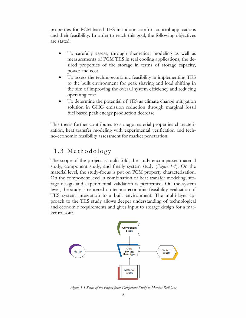
1 . 3 M e t h o d o l o g y The scope of the project is multi-fold; the study encompasses material study, component study, and finally system study (Figure 1-1). On the material level, the study-focus is put on PCM property characterization. On the component level, a combination of heat transfer modeling, sto-rage design and experimental validation is performed. On the system level, the study is centered on techno-economic feasibility evaluation of TES system integration to a built environment. The multi-layer ap-proach to the TES study allows deeper understanding of technological and economic requirements and gives input to storage design for a mar-ket roll-out.
Figure 1-1 Scope of the Project from Component Study to Market Roll-Out

4
The topic on thermal energy storage for indoor comfort control is first tackled with a review of literature on the current development of salt hydrate based TES. The state of the art on salt hydrate PCMs provides insights to matters encountered in the field of thermal storage.
This leads to the second phase of the project: building of numerical si-mulation models with the aim to accurately evaluate the thermal per-formance of storage unit. The modeling provides not only insights to the design of finned pipe heat exchanger units, but it also shows the in-terdependency between thermal power, storable capacity, and the envi-ronmental conditions under which the storage system has to cope with.
Next, a parametric analysis is performed to study the influence of ma-terial properties and geometry of finned heat exchanger on the perfor-mance of TES systems. The results show where the focus of TES de-sign should be placed, and which of the storage parameters will need to be carefully assigned.
An experimental setup is then fabricated and tested to validate the thermal energy storage model with hydrated-salt-based PCM. The expe-riments serve as verification and validation for the TES model. Fur-thermore, visualization of the phase change process with the storage unit is obtained. Finally, an industrial designed TES unit is evaluated for its technical performance. The final study in this thesis includes feasibili-ty assessment of TES for integration to the built environment and the corresponding GHG emission reduction that may be achieved cost ef-fectively.
All obtained results are published in scientific journals and international conferences, and are shared within the framework of International Energy Agency: Energy Conservation through Energy Storage (IEA-ECES) Annex 24 Material Development for Improved Thermal Energy Storage Systems.
5
2 Review of Thermal Energy Storage Materials
Latent heat thermal storage is one of the most promising technologies in terms of energy conservation, grid load alleviation, and energy securi-ty maintaining in a built environment. However, due to the low thermal conductive property of PCMs, thermal energy storage/extraction rates are low and need to be ameliorated through advanced system design with optimized storage layout. It is of primary importance to pursue ma-terial development so as to obtain novel PCMs with desired material properties that can provide sufficient thermal storage/extraction power, high ice packing factor (IPF, ratio of PCM volume to total tank vo-lume), and stable charge capacity. This section gives an overview on the currently available TESs and special emphasis will be placed on inorgan-ic salt hydrate. This chapter is based on the extensive literature review presented in Paper I.
2 . 1 C a t e g o r i z a t i o n TES systems are divided into two main categories: active and passive systems. Active TES systems are comprised of control mechanisms for charging and discharging of the storage. Passive TES systems, on the other hand, do not have any mechanical components. Examples of ac-tive storage system are ice scraping storage and TES implemented air conditioned systems; while passive storage systems can be PCM im-pregnated plasterboards in building envelops and TES used for insula-tion purpose.
Energy storage process can further be sub-categorized into physical sto-rage, via sensible heat and latent heat, and chemical storage through ex-othermic and endothermic reactions. An overview of the three types of storage process with their applications is shown in Figure 2-1.
Sensible heat storage is attractive in a large number of applications such as underground energy storage: aquifer thermal energy storage (ATES), borehole thermal energy storage (BTES), and cavern thermal energy sto-rage (CTES), where space uptake is not limited and where the resource is already made available. Sensible heat storage normally has the advan-

6
tage of requiring smaller heat exchange surface area between the storage and the heat transfer fluid due to better heat exchanger surface contact. In some applications, the energy storage medium is also the heat trans-fer fluid, such as hot water storage in households.
Figure 2-1 Categorization of Thermal Energy Storage (adapted from CompEdu)(Chiu, et al., 2011)
PCMs utilize the latent heat resulted from phase change to store and re-lease thermal energy. Advantages of using latent heat are narrow tem-perature fluctuation during charge and discharge of cold/heat, high sto-rage density as compared to sensible heat storage and temperature flex-ibility for application. The latent heat is obtained through change of state from solid to solid, solid to liquid, liquid to vapor, or solid to vapor. The most commonly utilized PCMs are solid to liquid phase change due to their smaller volume change as compared to that of liquid/solid to vapor, c.f. Figure 2-2 for ice/water/steam density change, and the ener-gy storage density is typically greater than that of solid to solid trans-formation.
In active LHTES system, where thermal energy has to be extracted and stored at certain required thermal extraction/storage rage to meet the end user demand, it has become a major concern to design TES system with adequate energy storage material so as to meet the thermal energy extraction/storage requirement. PCMs are classified into two main cate-gories: organic materials and inorganic materials. Eutectics are some-times considered as a third category; they are mixtures of organic and/or inorganic materials that have a fixed phase change temperature. Common organic materials are paraffins and acids, while inorganic ma-terials are salt hydrates and metallics. A non exhaustive list of the most
Thermal storage
Sensible heat storage
Solid
Boreholes
Rock
Liquid
Aquifer
Water Storage
Cavern/ Pit
Latent heat storage
Organic PCM
Paraffin compounds
Acids
Inorganic PCM
Salt Hydrates
Metallics
Eutectic PCM
Organic ‐ Organic
Inorganic ‐ Organic
Inorganic ‐Inorganic
Chemical thermal storage
Hydrates
Calthrate compounds
Mixture of solvent and solute

7
studied salt hydrates are sodium sulfate decahydrate, calcium chloride hexahydrate, sodium thiosulfate pentahydrate, sodium carbonate deca-hydrate, disodium phosphate dodecahydrate, and their derivatives.
Liquid water with molecular Water vapor with molar mass of 18.02g/mol volume of 22.41l/mol
Ice with 0.9167 g/cm³ at 0°C Water with 0.9998 g/cm³ at 0°C
Figure 2-2 Water volume increase at phase change (pictures taken from various sources)
2 . 2 P C M A d v a n t a g e s a n d L i m i t a t i o n s While PCMs show many advantages, a number of issues are yet to be overcome. Table 2-1 summarizes pros and cons of the common PCMs. First, non eutectic latent heat storage materials often do not have a fixed phase change temperature, their melting and freezing temperatures lie over certain temperature range. Second, the melting and the freezing temperature often differ from each other; this is known as the hysteresis of the material and cause a temperature swing in charging and discharg-ing of thermal energy. Third, subcooling is largely present in inorganic salt hydrates and it lowers the nucleation temperature to a level much lower than the solidification temperature. Fourth, flammability of organ-ic material and corrosive nature of inorganic salts often put extra con-straints and limitations on the containment of the storage. The fifth concern is the low thermal conductivity rate of PCMs; in active systems, this presents especially a bottleneck in storing and in extracting thermal energy at the required rate. The above listed drawbacks mark the chal-lenge in using PCMs in indoor thermal comfort control systems where the acceptable temperature swing is small.
Comparing organic and inorganic materials in terms of applicability, in-organic materials are non flammable and have higher volumetric energy storage density; on the other hand, organic materials undergo low level of phase separation and some are not affected by subcooling. Organic
1200 times
volume increase
10% volume
increase
8
materials have low thermal conductivity in the order of 0.2W/m-K, whereas inorganic materials have double to triple the thermal conductiv-ity reaching to that of water in the range of 0.4 to 0.6W/m-K. Nonethe-less, the thermal transfer of non gelled organic PCMs may be assisted by convection in the melt state. In summary, the choice of PCMs for use in energy storage depends on the specific application requirements as well as the constraints in the energy system.
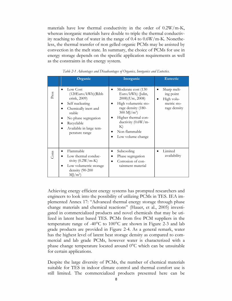
Table 2-1 Advantages and Disadvantages of Organics, Inorganics and Eutectics.
Organic Inorganic Eutectic
Pro
s
Low Cost (120Euro/kWh)(Ribberink, 2009)
Self nucleating Chemically inert and
stable No phase segregation Recyclable Available in large tem-
perature range
Moderate cost (130 Euro/kWh) (Julin, 2008)(Ure, 2008)
High volumetric sto-rage density (180-300 MJ/m³)
Higher thermal con-ductivity (0.6W/m-K)
Non flammable Low volume change
Sharp melt-ing point
High volu-metric sto-rage density
Con
s Flammable Low thermal conduc-
tivity (0.2W/m-K) Low volumetric storage
density (90-200 MJ/m³)
Subcooling Phase segregation Corrosion of con-
tainment material
Limited availability
Achieving energy efficient energy systems has prompted researchers and engineers to look into the possibility of utilizing PCMs in TES. IEA im-plemented Annex 17: “Advanced thermal energy storage through phase change materials and chemical reactions” (Hauer, et al., 2005) investi-gated in commercialized products and novel chemicals that may be uti-lized in latent heat based TES. PCMs from five PCM suppliers in the temperature range of -40°C to 100°C are shown in Figure 2-3 and lab grade products are provided in Figure 2-4. As a general remark, water has the highest level of latent heat storage density as compared to com-mercial and lab grade PCMs, however water is characterized with a phase change temperature located around 0°C which can be unsuitable for certain applications.
Despite the large diversity of PCMs, the number of chemical materials suitable for TES in indoor climate control and thermal comfort use is still limited. The commercialized products presented here can be

9
grouped into three distinct temperature categories: below 0°C, 0°C to 40°C, and above 40°C. It can be seen from the categorizations in Figure 2-3 that the commercialized products are based on the same chemicals blended with additives to reach new phase change temperatures; this in consequence lowers the storage capacity. For high thermal power and capacity demanding storage applications, there is thus an imminent ur-gency to develop and search for novel materials that exhibit suitable sto-rage properties.
Figure 2-3 Commercialized PCMs
Figure 2-4 Lab grade PCMs

10
2 . 3 R e s e a r c h D i r e c t i o n While inorganic materials, especially salt hydrates, are highly rated for their high energy density and the non flammable properties for integra-tion to the built environment, the phase separation and the subcooling constitute major obstacles to their implementation. To overcome these issues, addition of gelling agents to the salt hydrate mixture has been practiced to immobilize PCM so as to reduce the phase segregation. However, gelling also inhibits the flow of melted salt hydrate; this limits thus the convective heat transfer mechanism and brings down the heat exchange rate.
Research has been widely carried out to obtain novel additives and orig-inal gelling agents to ensure high material stability over repeating charge/discharge cycles while maintaining high heat capacity and high heat transfer rate. Salt hydrates suffer especially phase separation in re-peating charge/discharge cycles. A few of the common gelling agents utilized are bentonite, cellulose, and other substances as listed in Table 2-2 (left).
Subcooling is a result of phase change temperature shift where solidifi-cation occurs below its melting temperature. The subcooling can be li-mited through introduction of nucleating agents that facilitate crystal formations. Nucleating agents are particles scattered in the PCM for the purpose of forming artificial nucleating sites. A large number of nucleat-ing agents have been reported to have shown positive effect on subcool-ing reduction, notably borax (sodium borate, sodium tetraborate, or dis-odium tetraborate), powder (aluminium, carbon, copper), and other in-ert substances, see Table 2-2 (right).
Despite the high potential of LHTES in achieving improved overall sys-tem efficiency, only a relatively small number of results have been re-ported on successful system studies with high capacity and high power rated storage units. The research axes in terms of PCM development in the near future will be on a large extent on the lookout for more suitable material properties, namely higher thermal conductivity, improved sto-rage density, and lower material cost.
In the scope of this thesis, all feasibility studies will be based on the cur-rently available PCMs. The goals in this thesis are quantification of the interdependency among storage capacity, thermal transfer rate, storage component design, proactive control strategies, case studies with im-plementation of LHTES, and potential of TES as climate change mitiga-tion solution.

11
Table 2-2 Gelling, and Nucleating Agents, adapted from (Shin, et al., 1989)(Wang, et al., 2008)
Gelling Agents Nucleating Agents
Alginate Bentonite Cellulose Diatomaceous earth Polymer Polymeric polycarboxylic acid Silica gel Starch Thixotropic (attapulgite clay)
Aluminium Borax Carbon TiO2 Copper Na2SO4 SrSO4 K2SO4 Na2P2O7 SrCl2 BaI2 BaCl2 Ba(OH)2 BaCO3 CaC2O4 Sr(OH)2 SrCO3 CaO MgSO4
Acrylamide/acrylic acid copolymer (AACP) Sodium hexametaphosphate (SHMP, (Na-PO3)6)

12

13
3 Power & Capacity
The majority of the commercial PCMs have relatively low thermal con-ductivity; typical value ranges in between 0.2W/m-K and 0.7W/m-K (Hauer, et al., 2005). This characteristic marks the low thermal perfor-mance of TES and creates possible non-matching between thermal power supply and demand. Heat transfer enhancement techniques that provide sufficient thermal power are thus vital to ensure proper opera-tion of LHTES in the system.
The enhancement techniques are of many kinds, typical solutions are surface extension of heat exchanger and PCM thermal property ameli-oration. Examples of heat transfer surface increase are addition of Less-ing rings, fixation of fins on tube-type heat exchanger, impregnation of PCM in high conductive graphite matrices. As to material property en-hancement, examples are blending with highly conductive powders, not-ably graphite and aluminum powder.
Finned type heat exchangers with latent heat thermal storage have gained particular interest among the storage engineering community as the fabrication cost is relatively low and the level of engineering tech-niques is mature. However, there is a lack of standardization in TES performance assessment. Power, capacity and available energy source are the three main storage aspects and are interconnected in the design of a storage system. As a matter of fact, the TES performance is judged upon the capability of fulfilling the energy demand. In the prospect of this study, a numerical model was built to study the interdependencies of the above mentioned storage design parameters. Furthermore, an ex-perimental test rig was later constructed for model validation. This vali-dated model allowed representative parametric study of the LHTES and made this specific numerical model a design tool for PCM-based LHTES. The results presented in this chapter are based on papers IV and V.
3 . 1 M o d e l D e s c r i p t i o n
A heat transfer model for studying TES unit was created under Matlab. The model is a two dimensional fixed-grid finite-difference enthalpy based heat transfer simulation. Salt hydrate was chosen as the storage

14
material for it exhibits high energy density per storage volume and has non flammable property. For the considered gelled salt hydrate based PCM, conduction was the main heat transfer mechanism and was im-plemented to the numerical model. The solving of numerical model is based on the enthalpy method. The use of enthalpy-temperature (h-T) in phase change modeling was first developed by Date (Date, 1992), where material thermal property varies as a function of material temper-ature. In Date’s model, the latent enthalpy arises at a fixed temperature. A more generalized linear h-T over the phase change range was later implemented in LHTES simulations and showed better concordance for PCMs having phase change temperature range (Velraj, et al., 1997).
In this work, Heaviside function and its derivative were adopted in for-mulating heat capacity to temperature relation (Comsol Multiphysics, 2008); this allows the specific heat to be weighted over the considered phase change temperature with the maximal specific heat peaking at phase change temperature. The specific heat is formulated in 3-1.
· · · 3-1
with D (T) approximate derivative of the Heaviside function,
²²
√ · 3-2
Figure 3-1 Representation of cp(T)/L
One representation of the Dirac approximation, equation 3-2 is shown in Figure 3-1. In this example, the area below the curve, cp T .
T
L, ac-

15
counts for 95% of the total latent heat over a temperature range of Tpc±0.5°C. This mathematical formulation allows definition of the phase change temperature range, choice on the peak phase change tem-perature and in consequence determination of the enthalpy over a tem-perature range.
The finite-difference method was utilized in modeling the thermal per-formance of a finned-tube submerged heat exchanger TES unit. The general formulations of energy equations are shown below in 2D Carte-sian coordinates and in radial symmetric 2D cylindrical coordinates,
²
²
²
² 3-3
²
²
²
² 3-4
with α the thermal diffusivity,
· 3-5
Two scenarios have been proposed to identify the energy storage per-formance. The first scenario is set for a charging duration of 10 hours, while the second is granted for unlimited charging time. The model si-mulates charging of cold to a PCM based TES from 2°C above melting point to 2°C below. The driving temperature between the heat transfer medium and the PCM is taken as 9°C at the start of the charging. Other conditions considered in this simulation are listed as follows:
Fin thickness of 2mm Constant tube and fin temperature Equal fin and tube spacing Isotropic material properties Salt-hydrate PCM with phase change at 13°C (PCMProducts,
2007)
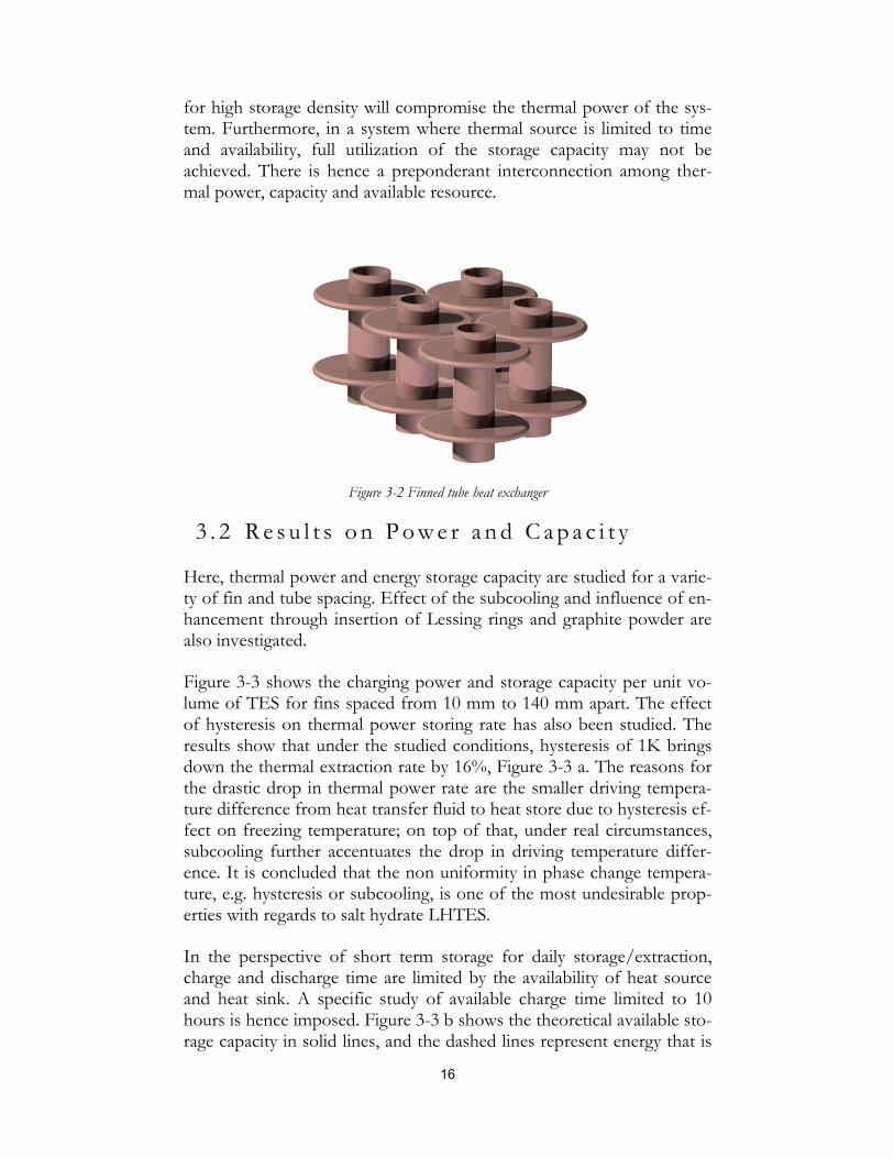
A graphical representation of the heat exchanger is shown in Figure 3-2.
The objective of the study is to demonstrate the interdependency be-tween the thermal extraction/storage power and the storable capacity as a function of available thermal source input. As the low thermal conduc-tivity of PCM has long shown to be the limiting factor in a LHTES, means have been adapted to increase the heat transfer rate of TES sys-tems. The improvement in thermal storage/extraction rate may, howev-er, under certain circumstances cause drop in system performance, such as decrease in overall thermal energy storage capacity due to decrease in IPF of the storage material. On the other hand, a non justified pursuit
16
for high storage density will compromise the thermal power of the sys-tem. Furthermore, in a system where thermal source is limited to time and availability, full utilization of the storage capacity may not be achieved. There is hence a preponderant interconnection among ther-mal power, capacity and available resource.
Figure 3-2 Finned tube heat exchanger
3 . 2 R e s u l t s o n P o w e r a n d C a p a c i t y
Here, thermal power and energy storage capacity are studied for a varie-ty of fin and tube spacing. Effect of the subcooling and influence of en-hancement through insertion of Lessing rings and graphite powder are also investigated.
Figure 3-3 shows the charging power and storage capacity per unit vo-lume of TES for fins spaced from 10 mm to 140 mm apart. The effect of hysteresis on thermal power storing rate has also been studied. The results show that under the studied conditions, hysteresis of 1K brings down the thermal extraction rate by 16%, Figure 3-3 a. The reasons for the drastic drop in thermal power rate are the smaller driving tempera-ture difference from heat transfer fluid to heat store due to hysteresis ef-fect on freezing temperature; on top of that, under real circumstances, subcooling further accentuates the drop in driving temperature differ-ence. It is concluded that the non uniformity in phase change tempera-ture, e.g. hysteresis or subcooling, is one of the most undesirable prop-erties with regards to salt hydrate LHTES.
In the perspective of short term storage for daily storage/extraction, charge and discharge time are limited by the availability of heat source and heat sink. A specific study of available charge time limited to 10 hours is hence imposed. Figure 3-3 b shows the theoretical available sto-rage capacity in solid lines, and the dashed lines represent energy that is

17
charged under 10-hour period for both with and without hysteresis. It is observed that the storage capacity may not be fully charged for a given 10-hour charge period for fins and tubes spaced farther than 80mm apart in this specific application. While with 1°C hysteresis, the total charged capacity is further decreased by 5%. This demonstrates the in-terdependency between resource availability, power and capacity, as well as the adverse effects of hysteresis on overall TES performance.
a.)
b.)
Figure 3-3 a.) Charging Power and b.) Storage Capacity for Various Fin Spacing with 1°C Hysteresis (dotted line)/ without Hysteresis (solid line)
The power and capacity study for enhanced PCMs, e.g. blending with graphite and insertion of Lessing rings, are compared with non en-hanced storage in Figure 3-4.
18
a.)
b.)
Figure 3-4 Finned Tube Thermal with/without enhancement a.) Power Rate and b.) Storage Capacity
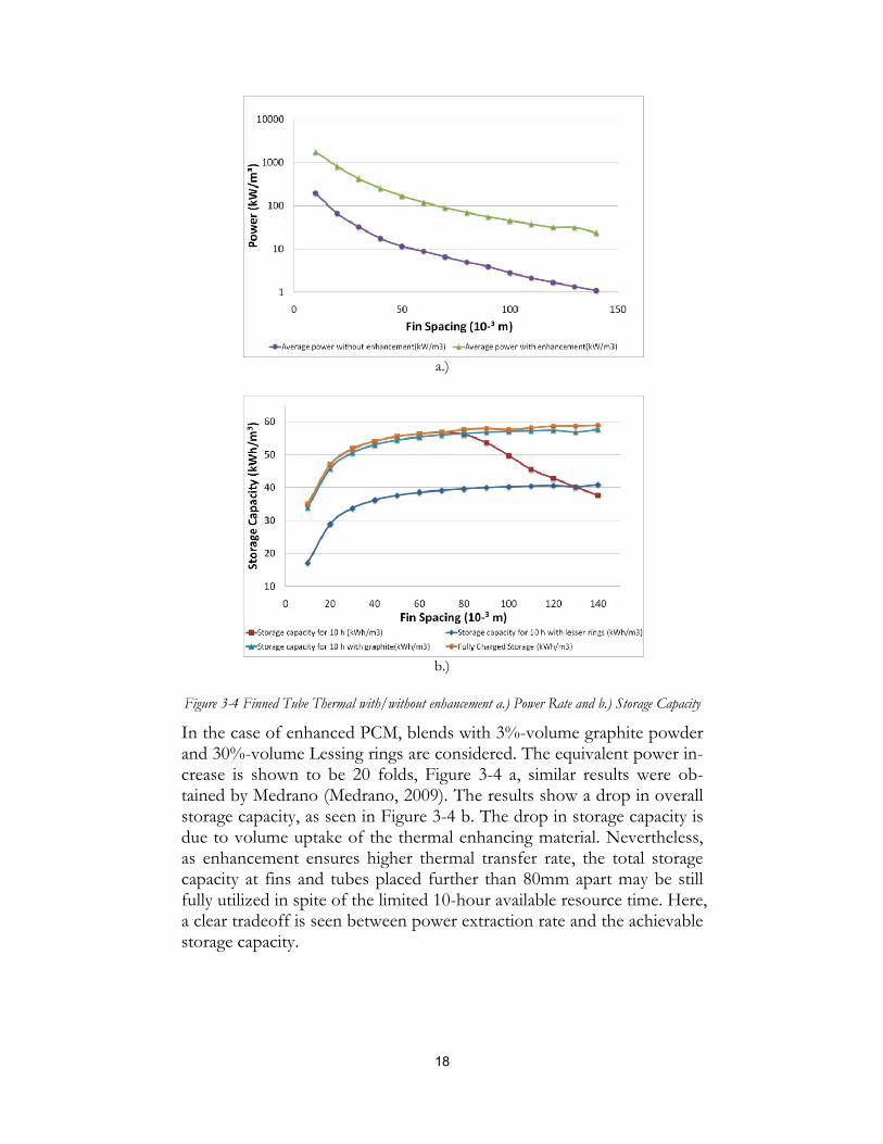
In the case of enhanced PCM, blends with 3%-volume graphite powder and 30%-volume Lessing rings are considered. The equivalent power in-crease is shown to be 20 folds, Figure 3-4 a, similar results were ob-tained by Medrano (Medrano, 2009). The results show a drop in overall storage capacity, as seen in Figure 3-4 b. The drop in storage capacity is due to volume uptake of the thermal enhancing material. Nevertheless, as enhancement ensures higher thermal transfer rate, the total storage capacity at fins and tubes placed further than 80mm apart may be still fully utilized in spite of the limited 10-hour available resource time. Here, a clear tradeoff is seen between power extraction rate and the achievable storage capacity.
19
3 . 3 C o n c l u d i n g R e m a r k s o n I n t e r d e p e n d e n c y o f P o w e r a n d C a p a c i t y
The theoretical study shows the close interdependency of the thermal energy extraction/storage rate and the utilized storage capacity for a giv-en resource availability. For a fixed available energy charge/discharge duration, e.g. free night time cooling and daytime solar heating, the thermal power rate determines the amount of storage capacity that can be replenished. During charge/discharge period, the required thermal power extraction rate constitutes the limiting factor for the TES system. An insufficient heat transfer system will lead to incomplete utilization of the total available storage capacity. However, an excessively high ther-mal power rated system requires higher volume uptake of the heat ex-changer and/or more generally of the thermal enhancing agents. This reduces the IPF of the TES and cuts down the storage volumetric ener-gy density. From this, it is concluded that the optimal balance between design of power and capacity is case specific and application dependent. A holistic understanding of the energy system requirement as well as meticulous design of the TES performance is essential in obtaining a functional and adapted solution in energy alleviation through load shift-ing and peak shaving.
Numerical models comprise assumptions that are very often case specif-ic. Verification of input data as well as output results through experi-mentation is crucial in terms of reaching for in-depth understanding of the actual phase change phenomena in charging and discharging processes. The following chapter is devoted to the characterization of PCM thermal properties, which was shown with parametric study as one of the most crucial factors in design of a LHTES.

20
21
4 Material Proper ty Characterization
In TES design and performance evaluation, accurate input data to the model is the key to correct assessment. In this section, a parametric study is presented to identify the core inputs. The Temperature-history (T-history) method in PCM property characterization is also elaborated. Further details on the material property characterization are presented in Paper V.
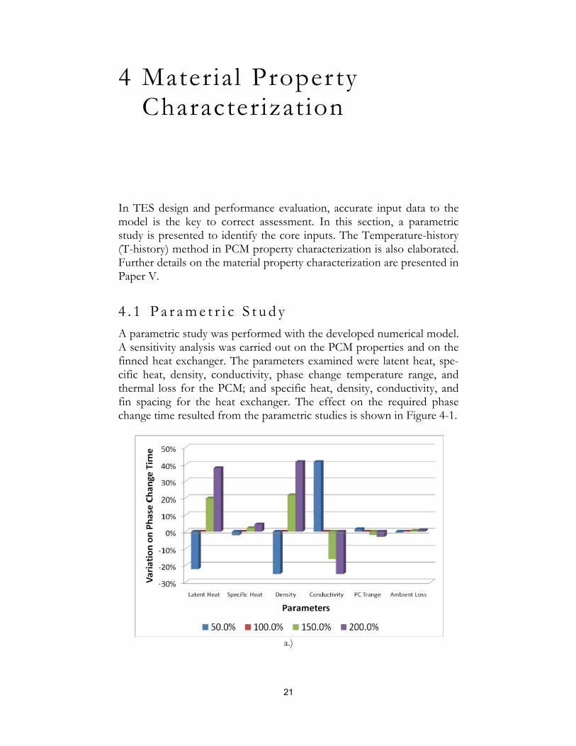
4 . 1 P a r a m e t r i c S t u d y A parametric study was performed with the developed numerical model. A sensitivity analysis was carried out on the PCM properties and on the finned heat exchanger. The parameters examined were latent heat, spe-cific heat, density, conductivity, phase change temperature range, and thermal loss for the PCM; and specific heat, density, conductivity, and fin spacing for the heat exchanger. The effect on the required phase change time resulted from the parametric studies is shown in Figure 4-1.
a.)

22
b.)
Figure 4-1 a.) Parametric Study on PCM Properties b.) Parametric Study on Fin Properties
In terms of PCM properties, latent heat, density, and conductivity are shown to be the key influential parameters on the storage performance. A doubled value of latent heat and density lead to 40% increase in phase change time, and a doubling in conductivity of the material will accele-rate phase change by 25%.
Regarding the parameters sweep of the heat exchanger, specific heat, density and conductivity contribute to more than 30% variation when doubled. While with double the fin spacing, the phase change time is in-creased by more than 100%. The fin spacing has thus the highest weighting factor among the studied parameters.
With this parametric study, it is also shown that high power can be reached efficiently without compromising the IPF with material im-provement of PCMs. On the other hand, material improvement on the heat exchanger is most unlikely as the material development for heat ex-changer has already reached maturity. In the scope of constructing a va-lid theoretical model for LHTES performance evaluation, the PCM en-thalpy, PCM thermal conductivity and PCM density must be carefully acquired and heat exchanger parameters finely assigned. A methodology for PCM heat capacity testing and specific heat modeling is proposed in this section.
4 . 2 T e m p e r a t u r e - H i s t o r y S e t u p Several techniques can provide PCM thermal properties, such as diffe-rential scanning calorimetry (DSC), differential thermal analysis (DTA),

23
bomb calorimetry, and others. Drawbacks of these systems are the li-mited sample size which may cause non homogenous sample measure-ment and user dependency where different configurations of the mea-suring setup lead to different results (He, 2004). One particularly inter-esting technique is the T-history characterization based on lumped ca-pacitance method. The method was first proposed by Zhang et al. (Zhang, et al., 1999), it was then improved and ameliorated by many others (Marin, et al., 2003)(Hong, et al., 2004)(Lázaro, et al., 2006)(Günther, et al., 2006) (Palomo, et al., 2011).
The T-history method relies on continuous comparison of temperature change of the test sample to a known reference sample. Identical sample holders ensure the same heat transfer rate to both samples under the same conditions. A blind is set up to limit eventual air draft and the heat source/sink is provided by humidity and temperature controlled climate chamber. The schematic is shown in Figure 4-2.
Figure 4-2 Schematic of the T-History Setup
The T-history method relies on the isothermal condition of the samples. This translates to a low external heat convective term as compared to in-ternal heat conduction, or small Biot number, equation 4-1. With the current experiment, the Biot numbers for the samples are below 0.1.
1 4-1
where U is the overall heat transfer coefficient from the climate cham-ber to the samples, r the radius of the sample holder, and k the thermal conductivity of the samples.
4 . 3 D i s c u s s i o n o n T h e r m a l P r o p e r t i e s The temperature of the climate chamber was cycled between 0°C and 40°C with each cycle lasting for 16 hours, the samples taken were 50±0.3g for the referenced distilled water sample and
24
65±0.5g/71.5±0.3g for two test samples. A detailed explanation on the calculation of the specific heat from acquired temperature profile is shown in the appended Paper V.
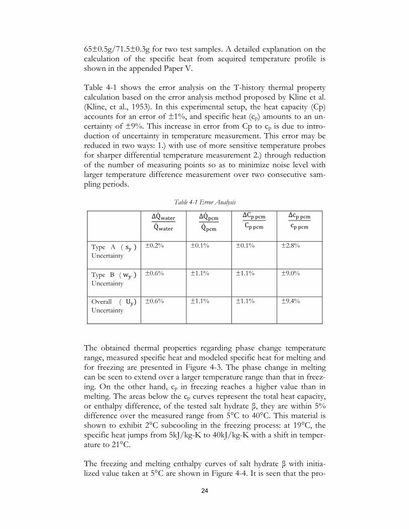
Table 4-1 shows the error analysis on the T-history thermal property calculation based on the error analysis method proposed by Kline et al. (Kline, et al., 1953). In this experimental setup, the heat capacity (Cp) accounts for an error of ±1%, and specific heat (cp) amounts to an un-certainty of ±9%. This increase in error from Cp to cp is due to intro-duction of uncertainty in temperature measurement. This error may be reduced in two ways: 1.) with use of more sensitive temperature probes for sharper differential temperature measurement 2.) through reduction of the number of measuring points so as to minimize noise level with larger temperature difference measurement over two consecutive sam-pling periods.
Table 4-1 Error Analysis
∆Q
Q
∆Q
Q
∆C
C
∆c
c
Type A ( s Uncertainty
±0.2% ±0.1% ±0.1% ±2.8%
Type B ( w Uncertainty
±0.6% ±1.1% ±1.1% ±9.0%
Overall ( U Uncertainty
±0.6% ±1.1% ±1.1% ±9.4%
The obtained thermal properties regarding phase change temperature range, measured specific heat and modeled specific heat for melting and for freezing are presented in Figure 4-3. The phase change in melting can be seen to extend over a larger temperature range than that in freez-ing. On the other hand, cp in freezing reaches a higher value than in melting. The areas below the cp curves represent the total heat capacity, or enthalpy difference, of the tested salt hydrate β, they are within 5% difference over the measured range from 5°C to 40°C. This material is shown to exhibit 2°C subcooling in the freezing process: at 19°C, the specific heat jumps from 5kJ/kg-K to 40kJ/kg-K with a shift in temper-ature to 21°C.
The freezing and melting enthalpy curves of salt hydrate β with initia-lized value taken at 5°C are shown in Figure 4-4. It is seen that the pro-

25
posed adapted Dirac formulation provides good thermal property curve-fit in the sensible heat regions; however, this representation cur-rently does not consider the subcooling in freezing, nor the asymmetric behavior in melting. Implementation of the subcooling aspect as well as the asymmetric behavior in thermal property curve fit will be inspected in future work. In this thesis, an experimental validation was carried out on TES modeling with the proposed adapted Dirac formulation over the full phase change.
Figure 4-3 Specific Heat of Salt Hydrate β
Figure 4-4 Enthalpy Representation of the Salt Hydrate β

26

27
5 Heat Transfer Model Validation through Experimental Work
LHTESs show the advantage in providing adequate thermal sto-rage/extraction temperature, exhibiting small temperature swing and re-quiring small volume per unit of storage capacity. The major drawback is however the low heat transfer rate due to the thermal properties of the material. Extracting sufficient thermal power for use in applications constitutes a major obstacle for successful implementation of such sys-tem to the built environment. Many researchers have looked into heat transfer rate enhancement through improvement of heat exchangers, optimization of heat storage parameters, and creation of novel PCM blends with high thermal conductive particles. However, only limited re-sults have so far been reported on salt hydrates based LHTES. An expe-rimental rig was constructed to evaluate the numerical model. This test rig provides valuable information and serves as a background study for future TES system designs that will be modeled and fabricated within the framework of this PhD project. The work presented in this chapter is based on paper V.
5 . 1 E x p e r i m e n t a l S e t u p The constructed rig was a 0.65 liter storage tank built with poly-methyl-methacrylate (PMMA) glass envelop in the aim of providing insulation to the TES system and better visualization of phase change process. The heat exchanger was a finned tube heat exchanger with 2mm thick fins spaced 30mm apart, Figure 5-1, left. The tube and fins were built in Aluminum Alloy 6082 (AL 4212). The tube diameter measures 10mm with wall thickness of 1.5mm. The TES was charged and discharged with a temperature controlled water bath, Lauda Alfa RA8. Tempera-tures were taken on the fins, along the tube, and in the PCM between the fins at 15mm from the axial of the heat exchanger tube, Figure 5-1 right. Ambient air, inlet and outlet of the heat transfer fluid tempera-tures were also logged.

28
T fin low
T fin high
T fin mid high
T fin mid low
T PCM high
T PCM mid
T PCM low
T in
T out
T pipe in
T pipe out
T pipe mid
Figure 5-1 Tank Shell (left), Placement of Thermocouples (right)
The schematic of the experimental setup is shown in Figure 5-2. The water bath serves as both the heat source and heat sink for charging and discharging of the TES unit. A pump regulates the flow of HTC to the TES. The temperatures were logged with Keithley 2701 equipped with multiplexer card 7706, at a sampling rate of 0.1 Hz. Acquisition software used on computer was Keithley ExceLINX-1A version C04.
Pump
Water Bath
ComputerData
Logger
Thermal Storage
Figure 5-2 Data Acquisition Scheme
5 . 2 R e s u l t s Experimental verification and validation of the numerical code are the main focus of this study. Salt hydrate was utilized as PCM and water was utilized as HTC in the setup. In the cooling process, the PCM was initia-lized to a temperature of 29°C, heat was then extracted with HTF at 11°C. In the heating process, the PCM was initialized to 15°C, and heat was brought in with HTF at 32°C. The pump delivered the flow rate at

29
4.5l/min ±0.1l/min. The experimentally obtained and numerically cal-culated temperature evolution of inlet HTF, fins, and PCM were rec-orded and are shown in Figure 5-3 for cooling a), and for heating b). The three PCM temperatures shown correspond to the average PCM tem-perature measured between the fins for the three test runs. The fin tem-perature presented is the average temperature of fins at 15mm from the axial of the heat exchanger. Due to recirculation of the HTF from TES outlet to the water bath, the HTF at the inlet of TES was shown to have a small temperature fluctuation at the start as the control tend to equa-lize the fluid temperature to the set value.
a.)
b.)
Figure 5-3 Experimental Validation for a.) Cooling and for b.) Heating

30
The verification of the numerical results with experimental data was done through a comparison of required charging/discharging time to reach the same final temperature. Three experimental runs were per-formed. The data show good concordance of the temperature profiles obtained from the numerical and the experimental data. The experimen-tally obtained cooling times differ ±1% from the mean value. The expe-rimentally obtained heating curves are within ±5% difference from the mean heating time. By comparing the models to the experiment, both cooling and heating simulations give estimation within ±5% difference from the experiments. A summary is provided in Table 5-1.
Table 5-1 Numerical and Experimental Comparison
Run Start Tempera-ture (°C)
End Tempera-ture (°C)
Time Re-quired (s) Deviation
1 29 15 3930 0% 2 29 15 3940 1% 3 29 15 3860 -1% Numerical 29 15 3700 -5%
Run Start Tempera-ture (°C)
End Tempera-ture (°C)
Time Re-quired (s) Deviation
1 15 29 4470 -1% 2 15 29 4290 -5% 3 15 29 4730 5% Numerical 15 29 4330 -4%
It is observed that the time required for cooling is in average 15% faster than for heating. This may be explained by two reasons. The first is that the HTF was set at different temperature from the average phase change temperature in cooling as compared to heating. The second rea-son is that the phase change temperature range in melting covers 4°C, while the temperature range in solidification is 1°C. This indicates the higher driving temperature difference in cooling, hence the faster phase change process.
5 . 3 C o n c l u d i n g R e m a r k s The model successfully predicts the charge and discharge rate of a salt hydrate based TES within 5% difference. It is shown that conduction based model allows prediction of thermal behavior of gelled salt hydrate filled TES. However, accurate knowledge on material thermal properties has a predominant role in attaining correct simulation results. The HTF

31
temperature was also shown to be one of the main factors that have ma-jor impact on the charge/discharge time. In the next section, a system feasibility study is presented for integration of TES to a built environ-ment, notably a district utility connected office building.

32

33
6 System Integration and Feasibi l i ty Assessment
Economical feasibility of integrating small scale thermal energy storage in the built environment connected to the district cooling network was performed. Cost comparison was made for auxiliary chillers, stratified chilled water storage (SCW) and PCM based TES. It has been found that upon large storage/extraction power requirement, chilled water sto-rage or auxiliary chillers provide more economical viable solutions. The case study presented herein shows viability of storage solution of 13kW (5%) peak power shift against chilled water storage and 24kW (9%) power shift against chillers. The results were obtained with PCM at €5/kg and with tariff penalty for low return temperature back to the network system. This penalty is due to the fact that end user pays for the flow provided by the utility company independently of the return temperature. It is concluded that higher power shift with use of LHTES can be achieved economically with lower PCM cost and eradication of low return temperature penalty. This work is based on paper II.
6 . 1 A s s e s s m e n t D e s c r i p t i o n
The studied case consists of utility company providing district cooling at 6°C and a return temperature at 16°C. This gives a corresponding tem-perature of 8°C supply and 18°C return on the consumer’s side. The goal of the study is to investigate the potential of using a storage system at the end user side to shift peak cooling demand cost effectively as compared to other cooling solutions. The concept is to store cold at night with 8°C supply temperature and to extract cold during peak de-mand for dry cooling at 14°C during daytime office hours. Figure 6-1 depicts the supply and return temperature during charging (solid line) and discharging (dashed line). Outlet temperature in charging is assumed to be 12°C and in discharging as 14°C.

34
Figure 6-1 Schematics of Charging (solid line) and Discharging (dashed line)
It is noted that LHTES introduces two pinch temperatures: from supply to storage and from storage to user. The charge/discharge driving tem-perature difference may be altered based on the phase change tempera-ture of the PCM. This also means that a higher charging rate can be reached with a trade off to a lower extraction rate and vice versa. This is considerably interesting in the design of a TES for an uneven charge and discharge power requirement.
All non eutectics have a phase change temperature range. The melting temperature tends to approach higher bound of the phase change tem-perature range, and the freezing temperature tends to approach the low-er end of the phase change temperature range, an additional required pinch temperature is thus introduced. The phase change temperature is, in this specific study, taken at a fixed temperature.
The desired office dry cooling temperature is 14°C in the studied case. In order to reach high thermal energy extraction rate during cooling, the PCM needs to have as low phase change temperature as possible. How-ever, in order to minimize the penalty on cold return temperature during charging of TES during off peak period and to maximize the charge
Dry Cooling
Charging
PCM Phase Change Temperature at 13°C
Inlet 18°C
Inlet 8°C
Outlet 14°C
Outlet 12°C
Figure 6-2 Charging and Discharging Temperature Profiles

35
thermal power, a sufficiently high phase change temperature is required. As charge and discharge are equally important in the current system, PCM S13 with phase change temperature at 13°C is proposed. This re-sults in equal charge and discharge power with 8°C inlet for charging and 18°C for cooling, c.f. Figure 6-2. Salt hydrate PCM S13 was there-fore considered in the scope of this feasibility study.
Here, a single type PCM filled TES is considered. It is noted that with single PCM filled TES, the storage unit acts as a concurrent heat ex-changer. For instance, in cooling, the outlet temperature of the HTF never surpasses that of the PCM. This aspect makes the TES a compo-nent with low overall heat transfer efficiency especially during phase change process, similar results have been obtained by other research groups (Dincer, 2002), (Gong, et al., 1997). The multiple PCM filled TES will be goal of future system feasibility study.
The model created in this study is composed of three major modules. The three modules are: 1) dimensioning of the heat exchanger as so to cope with the required thermal power demand; 2) assessing storage vo-lume and tank size in order to reach the required energy capacity; and 3) estimating the economic feasibility as compared to auxiliary chiller based units and to stratified water based storage for peak shaving. In terms of the techno-economic feasibility comparison, the costs considered in-clude: initial capital investment for PCM, storage tank, and installation; maintenance and operation cost, such as space renting and control sys-tem/utility; and district cooling/electricity energy cost.
The model created is used for sizing and evaluating an actual 5-day of-fice peak cooling load in summer, the office building is located in Stockholm. The following assumptions and conditions are considered:
• For space optimization, storage must be completely cycled during the peak load period in the modeled time frame.
• The total storage capacity is sized to fulfill the peak day load demand.
• The storage level at the end of the five-day period must be equal to or higher than the storage level at the start of the discharge so as to sustain the system.
• Storage heat exchanger is sized to the discharge power need, maxi-mum charging rate is taken the same as the discharge rate so as to mi-nimize the heat exchanger size and hence maximize IPF of the tank.
• The storage does not supply for the off-peak demand.
• The TES system is at 50% of its full capacity at the start of the 5-day simulation period.

36
• The end user load profile is known and the control strategy is adapted to this user load.
• SCW system with 8K water storage temperature difference is consi-dered for the comparison.
• Economic analysis is carried out with 15 years depreciation time and an interest rate of 6%.
• Life span of chiller units corresponds to that of TES systems.
• District network provided and auxiliary chiller run cooling are at the same cost.
6 . 2 F e a s i b i l i t y R e s u l t s
The study was carried out to determine the feasibility of salt hydrate based LHTES as compared to auxiliary chiller and SCW storage. Results indicate that in the current Swedish market system and with present ma-terial pricing, the cost breakeven point of SCW and PCM-based storage can be reached at 13kW peak shaving for the considered office building.
Both the cost of water tank and the cost of PCM represent about half of the total system costs, Figure 6-3. The high cost in water tank is mainly due to low energy storage density of SCW unit, hence large tank volume. As to higher storage density PCM based TES, the cost of PCM per sto-rage unit makes up the high system cost. This brings up the total system cost when larger energy storage unit is needed.
a.)

37
b.)
Figure 6-3 Cost Distribution of a.) SCW storage and b.) PCM storage at Cost Breakeven Point
As the PCM constitutes the major share of the total LHTES cost, eco-nomic viability may be most easily leveraged through fluctuation in PCM price. Figure 6-4 shows the PCM Cost Ratio against SCW and against auxiliary chiller for different peak power reduction rate. The PCM cost ratio is defined as the ratio of calculated PCM cost to the cur-rent market PCM cost for achieving cost effective solution,
6-1
The graph can be read as: at cost ratio of 1 (current PCM price, dashed line), PCM based TES is cost effective against SCW for 13kW or less of peak power shifting, and it is economical against auxiliary chiller for 4kW to 24kW of peak power shifting. Now, considering 18kW of peak power to be shifted due to an increase in internal load demand, three possible solutions are: Chiller, SCW or PCM based LHTES. When compared with the chillers, PCM based TES is more economical and PCM price has an extra 25% cost margin; however PCM based TES is only economically suitable against SCW if the PCM price is cut down to half of its current price, intersection of SCW and 18 kW (solid line). This study shows the pivotal importance of decreasing PCM market price in competing with SCW and Chiller based technologies. In the studied case with peak 274kW cooling demand, LHTES is cost effective for a maximum peak shaving of 13kW. This corresponds to 5% of total peak cooling demand.

38
Figure 6-4 Profitability Analysis with Low Return Temperature Penalty
6 . 3 T e c h n o - E c o n o m i c F e a s i b i l i t y L o o k o u t
This techno-economic assessment of a specific office building in Stock-holm shows both economic potential and limitations of PCM based TES when integrated to an existing system. From the study, two major constraints were revealed in implementing TES systems in the Swedish society. The first is the non adequate tariff system from the energy pro-viders which limits the economic advantage of peak load displacement. As a matter of fact, the end user pays the same tariff during peak and off-peak periods; furthermore the price on district cooling is flow vo-lume based, this generates penalties for end users charging storage dur-ing off peak period. The second drawback is energy and exergy loss as TES acts as heat exchanger in charging, in storing, and in discharging, which introduces additional loss to the energy system.
An additional remark regarding the cost effective dimensioning of TES is the non full charge and non full discharge of the storage during peak demand days. Figure 6-5 shows the end-user cooling demand and re-quired cooling supply from utility company with implementation of TES aiming for 40% of peak shaving. The 40% peak shave is chosen for better graphical representation reasons. From the curves, we observe that storage is fully charged during off-peak periods in both day 1 and day 2; in day 3, the cooling demand is higher and storage cannot be fully replenished; then the storage is fully charge by the end of the following charge period by day 5. From this TES system setup, the storage is de-signed for a higher capacity so as to meet the peak demand on day 3 and
0
0.5
1
1.5
2
0 10 20 30 40 50 60
PCM Cost Ratio
Power Reduction Rate (kW)
SCW
Chiller

39
day 4 where full recharge cannot be achieved. The extra installed storage capacity is however utilized only on one occasion and this results in higher material cost as well as larger space requirement. One solution for cost cut down would be to improve the thermal storage power rate for charging. Nevertheless, if improperly designed, this power en-hancement would also have a detrimental effect on the overall system performance as shown in section 3 and lead to non cost effectiveness.
Figure 6-5 Cooling Demand and Load Supply for 40% Peak Shaving
These results give preliminary insights to the economic feasibility of LHTES integration in a built environment. The system dynamics, how-ever, still require our attention since a reliable control will ensure the proper operation of the charge/discharge mechanism. In the next chap-ter, we will look into an operational LHTES system designed for charg-ing free night time cold for use during warm daytime period.

40

41
7 Evaluation of a Commercial TES Prototype
A field evaluation of an active air to PCM storage unit for cooling of a habitation zone has been carried out to provide further insight to LHTES. This work was done under the framework of European Coop-eration in Science and Technology- Short Term Scientific Mission (COST- STSM), with University of Lleida, KTH and Ecostorage Swe-den in collaboration. The evaluation was carried out in two cubicles un-der real operational conditions in Puigverd, Spain. This section is based on detailed evaluation presented in paper III.
7 . 1 P r o t o t y p e D e s c r i p t i o n
Ecostorage Sweden, a delegate to the COST Action: Next generation cost effective phase change materials for increased energy efficiency in renewable energy systems in buildings (NeCoE-PCM), developed a PCM-based cooling unit which stores and extracts outdoor free-cold for cooling of buildings. In this unit, 40kg of PCM type C21-22 (Climator, 2003) is used for thermal energy storage. The storage is charged with outdoor free cold to meet peak indoor peak cooling demand, notably during day time. The wall hung unit is dimensioned 100cm length x 40cm height x 16cm width; it was designed for an approximate 2kWh cooling capacity and 200W power extraction rate.
The storage unit is charged and discharged with ventilation of air through the pipe heat exchanger. The fan dimension is crucial in this unit as a too large fan would increase the electricity consumption, and reduces the overall coefficient of performance (COP) of the system; while a too small fan would lead to insufficient charging of storage and puts at risk the overall storage system performance. The prototype is capable of 18L/s ventilation rate which allows air to pass through the parallel tube-type heat exchanger. The heat exchanger is an assembly of staggered 15 rows of 12mm diameter tubes constituting 68 parallel tubes measuring 60cm in length; the layout of the tube-type heat exchanger is shown in Figure 7-1. Advantage of such design is simplicity in construc-

42
tion and low pressure drop through the heat exchanger. Figure 7-1 shows a thermal analysis during melting (discharging of cold). The thermal image shows a delay in cold extraction of the PCM material along the outer layer of heat exchanger pipes which suggests further im-provement to the heat exchanger layout is possible.
Figure 7-1 Staggered Tube Heat Exchanger Model
Ecosaveit Cool is fitted with a control system that enables integration with ambient free cooling through two 100mm diameter air channel to the outside – one inlet and one outlet, and two air ducts to the interior of the room – one inlet and one outlet. The operation scheme is pre-sented in Figure 7-2. The control system determines the optimal configu-ration to maintain the indoor air at the set-point temperature through charge and discharge of the storage, and supply of free cooling to the in-terior with ambient cold air.
Figure 7-2 Schematics of the Setup

43
The temperature measurement probes are thermo-resistances type PT1000 placed to measure operating temperatures at the following posi-tions as shown in Table 7-1. In addition, fan power and air valves open-ing are also monitored.
Table 7-1 Thermo-resistance Placement
Numbering Position Numbering Position
GT1 Room GT3 Outdoor air temperature
GT2 Air temperature after PCM
GT4 PCM tempera-ture
Figure 7-3 Operation Schemes
During the cold charging process, air can be circulated through the unit from either outdoor or indoor depending on the temperatures. Air at the outlet of the storage can be either exhausted to the outdoor or redi-rected into the room depending on the requirement. Cases 3, 4 and 5 shown in Figure 7-3 represent the charging of PCM. In the cooling process, if outdoor air is at lower temperature than the interior, then outdoor air is delivered to the room, Figure 7-3 cases 1 and 3. It can be

44
seen that cases 1 and 3 are the optimal cooling cases where free cooling is used in combination with TES while providing cooling power to the room. On the other hand, if interior air is cooler than the outdoor am-bient air, the demand for cooling is then met through recirculation of indoor air through the TES, Figure 7-3 case 2. As to case 6, the storage is at its idle state where PCM is either depleted from its cold storage or there is no cooling demand. The alternative scheme for cases 1, 2 and 3, is when the room temperature is well below the set-point temperature and no cooling is needed, then all circulation to the room is switched off.
In the evaluation of the prototype, the power for charging and discharg-ing is evaluated as follows,
. . 7-1
Since the inlet air is a mixture of outdoor ambient air and indoor room temperature air, we obtain
. . 7-2
With Valve the percentage of the valve opening, hence
. . . . . 7-3
On the other hand, if the heat exchanger efficiency is 100%, Tout will be at the same value as TPCM, this leads to the formulation of theoretical charging and discharging PCM power,
. . . . . 7-4
The ratio of real charge/discharge PCM rate to theoretical charge/discharge PCM rate is given as
7-5
The cooling power that is supplied to the room after charg-ing/discharging the unit is given as
. . 7-6
7 . 2 R e s u l t s a n d E v a l u a t i o n o f t h e P r o t o t y p e
The “Ecosaveit Cool” prototype was evaluated for both its thermal power rate and its capacity. When free cooling is possible, the perfor-

45
mance of the system is largely influenced by the thermal inertia of the building. As a matter of fact, free cooling power is increased when in-door room temperature increases at a faster rate than the ambient out-door temperature during the day; or when outdoor ambient air tempera-ture drops faster than indoor room temperature during the night. This increase in cooling power is observed at several occasions during the test runs of the prototype. The cooling power supplied to the room is most often doubled during the cooling period as shown in Figure 7-4.
Figure 7-4 Measured Charging Power, Power Ratio and Power of Cooling Supplied to Room: Normal Operating Mode
In the normal operation mode, it is shown that the power ratio, in other terms the heat exchanger efficiency, reached 80% for all three charge periods. The cooling supplied to the cubicle ranged from 60W to 120W, while the charging of TES averaged at 80 W and peaked at 200W. The three operating periods mark three different operation modes:
1.) The first represents charging of TES and cooling of the room (case 3), we observe an increase in power of charging of cold to the TES and an increase in cooling power sent to the room due to outdoor temperature drop.
2.) During the fan off period, PCM in the TES is heated up pas-sively by the room through natural convection; the room tem-perature and the PCM temperature are below the set-point temperature.
3.) When the room temperature and the PCM temperature increase above the set-point, the fan starts up again.

46
In the goal of evaluating the total storage capacity of LHTES in a com-plete discharge/charge cycle, the storage was brought through several distinct test phases as shown in Figure 7-5. A 400W internal gain was placed inside the cubicles, leading to Figure 7-3 scheme 2, to force the discharge of the storage, phase A. The storage unit was then put back to normal operating mode and the charging of storage took place, phase B. The charging power reached 180W and the total cooling power supplied to the room achieved 160W. As the outdoor ambient temperature started to increase in phase C, the charging power of storage was re-duced, nonetheless the cooling power provided to the cubicle stayed at quasi constant 130W. In phase D, the charging of storage resumed due to cooler outdoor ambient temperature. The charging power decreased from 180W in phase B to 100W in phase D, one hypothesis is that the solidified PCM around the heat exchanger increased thermal resistance, hence reduced the charge power. In phase E, we experienced a dis-charge of thermal storage, the cooling power attained 70W, while the extracted power from PCM was merely 20W due to low temperature driving force between the ambient air and the PCM.
Figure 7-5 Measured Extraction/Storage Power, Power Ratio and Power of Cooling Supplied to Room: Complete Discharge and Charge Cycle
7 . 3 P r o t o t y p e E v a l u a t i o n R e m a r k s The control strategy setup implemented in Ecosave Cool unit is shown to provide adequate cold storage and cooling power to the indoor envi-ronment. The TES charging power peaked at 200W with an average at 140W. The power ratio in the studied temperature range reached value
A B
C
D
E

47
of 80% to 95%, this suggests a high heat exchanger efficiency. Nonethe-less, if higher cooling power rate is required, hence higher HTF flow rate, the finned type heat exchanger should be considered as it provides enhanced heat transfer surface and hence is more likely to maintains the power ratio with an increased air flow rate.

48

49
8 TES as Climate Change Mitigation Solution?
TES is shown to have positive contributions in terms of peak load allev-iation and on-peak load shift so as to increase the overall system effi-ciency. In this section, we will identify the potential in using TES for greenhouse gas (GHG) emission reduction in the Swedish energy sys-tem through reduction of fossil fuel based marginal electricity and ther-mal energy production. This study is composed of an overview of Swe-dish energy use, a presentation on the methods considered for GHG reduction, and results on the potential GHG emission reduction. This section is based on paper VI.
8 . 1 O v e r v i e w o f S w e d i s h E n e r g y U s e Sweden is among the world leading countries with the highest share of renewable energy use reaching 45% of total energy use (Swedish Energy Agency, 2009). In indoor thermal comfort, however, heating and cool-ing amount to more than 45% of the total energy use in Swedish resi-dential and service sector (Swedish Energy Agency, 2009). This section exploits the possibility of further reduce the non renewable share in the energy system through use of TES for indoor climate control.
Figure 8-1 shows the monthly conventional thermal power production and wind generated electricity over the last decade. Due to increase in electricity demand in winter time, we observe a double to triple of the conventional thermal power production rate, i.e. 700GWh of electricity was produced in July 2009 against 2500GWh in Feb 2010. Wind energy, as a renewable energy source, on the other hand, does not contribute to any marginal electricity production as the availability is limited. The marginal electricity production often rhymes with lower energy efficien-cy and lower level of flue gas treatment. Out of the 146TWh annual electricity production, 4.3TWh comes from fossil fuel based electricity generation. It is thus of primary importance to find means to reduce the fossil fuel dependency which will lead to decrease in CO2 emission.

50
Figure 8-1 Monthly Electricity Production (from wind and thermal power plant) in Sweden in the Last Decade, adapted from ENTSOE (European Network of Transmission System Operators for
Electricity, 2011)
The indoor thermal comfort control in Sweden is divided into district based and individual heating. Figure 8-2 shows the share of different sources based contribution to the district heating in Sweden. Fossil fuel heating amounts to 17.5% and electricity based thermal production reaches 12%. A substantial amount of fossil fuel may be avoided if it is possible to shift fossil fuel based marginal load to off peak period with use of renewable energy sources.
Figure 8-2 Supplied Energy to District Heating in 2009(Swedish Energy Agency, 2010)

51
8 . 2 M e t h o d f o r G H G R e d u c t i o n GHG emission reduction can be achieved through several means. One of the most direct methods is to shift fossil fuel produced marginal peak energy to off-peak period with TES. The avoided marginal energy pro-duction will be replaced by off-peak non polluting means of electricity and thermal energy production and leads thus to substantial amount of GHG emission reduction.
Figure 8-3 shows the schematic of the energy system in the study. The heating means considered in the study are oil burner, heat pump and electric heater based systems. The marginal energy sources are fossil fuel. The TES units placed between energy suppliers and end users provide marginal peak thermal load to users. Fossil fuel use is decreased and the GHG emission is reduced. The economy of the TES is considered on the overall system level, this means that the initial capital cost for the in-stallation and the return on investment is shared among energy suppliers and the end users. The payback on TES is done through cost saving on fossil fuel, on CO2 tax and on plant operation. In the current energy structure, only utility companies receive direct cost benefits with TES system installations and not the end users; adequate policies are yet to be set up to promote this.
Figure 8-3 Considered Energy System (left) and Thermal Production Means (right)
8 . 3 L i n e a r O p t i m i z a t i o n M o d e l The model constructed is based on a linear optimization scheme. The cost of TES implementation follows a learning curve which takes the following form,

52
8-1
with LP the learning parameter, C the new unit cost, C0 initial unit cost, X accumulated capacity, and X0 initial cumulative capacity
The learning parameter is defined with the learning rate (LR),
1 2 8-2
The learning rate is high for a technology at its infancy and decreases as the technology reaches maturity. The learning rate adopted in this study for TES technology is taken from the learning rate for indoor air condi-tioning studied and categorized by Ferioli et al. from compilation of 108 applications (Ferioli, et al., 2009).
The objective function is established to minimize the cost difference be-tween TES installation, saved fossil fuel cost and avoided pow-er/thermal plant cost so as to reach a cost breakeven point for a max-imal fossil fuel replacement while maintaining cost effectiveness of the system. The objective function is expressed as the Peak Shave Cost (PSC),
PSC= TESC-PCR-AFFC 8-3
where TESC is thermal energy storage cost, PCR is the production cost reduction, and AFFC is the avoided fossil fuel cost (including CO2 tax).
The production cost reduction represents the cost saving on fixed oper-ation and maintenance (FOM) and on variable operation and mainten-ance (VOM). The FOM is a cost coming mainly from the rating of the production or the peak shaved power (PSP), while the VOM is a cost from the capacity of the production or the peak shaved load capacity (PSL). The PCR is expressed as follows,
PCR=PSP*{FOM*[1-(1+R)-N]/R}+ PSL*{VOM*[1-(1+R)-N]/R} 8-4
With the number of payments, N, taken as 20 years and the discount rate, R, taken as 6%.
The AFFC is the total peak shaved fuel cost,
AFFC=FRSCoal*CCoal+FRSGas*CGas+FRSOil*Coil 8-5
with FRS the fuel reduction share and C the fuel cost.
53
8 . 4 R e s u l t s a n d D i s c u s s i o n s o n C O 2
M i t i g a t i o n P o t e n t i a l On top of the currently available measures taken for GHG emission al-leviation in the Swedish society, TES gives possibility to further reduce GHG emission. The cost breakeven point for TES implementation against marginal fossil fuel saving is met with an installation of 14GWh storage system. This storage allows a replacement of 2TWh/year fossil fuel based thermal power production and 0.5TWh/year of fossil fuel based electricity production. The emission reduction achieved corres-ponds to 620kTon CO2/year, which represents 13% of the fossil fuel based GHG emission in residential and service sectors, or 1.1% of the Swedish annual emission.
In this study, displacement of heating load in residential and service sec-tors with TES is shown to lead to environmental benefit. It is believed that free cooling, absorption cooling, solar heating, and waste industrial heat may lead to further GHG emission reduction. In the future work, we will consider the potential of utilizing cold storage for load displace-ment through use of free cooling and off-peak cold production as well as heat storage combined with solar heating.

54

55
9 Discussion and Conclusions
The overall objective of this thesis has been to shed light and to provide novel knowledge in the field of thermal energy storage in terms of: 1) overall storage performance and characteristic mapping, e.g. application studies on interdependency between power and capacity, and model es-tablishment with meticulous material characterization; 2) advanced knowhow in design of technically and economically robust storage sys-tems for integration to the built environment, e.g. incorporation of LHTES to a district cooling network for office cooling; and 3) potential analysis on sustainable development contribution, e.g. GHG emission reduction through peak shaving and load shifting.
A major contribution of this work has been the clear identification of the dynamic interdependency between the thermal power rate and the storage capacity as a function of resource availability for adequate TES design. For example, this dependency has been shown to be particularly significant as seen through the application studies where thermal re-source availability was limited in time. A TES with too low heat transfer rate to allow full replenishment of the storage during charg-ing/discharging cycle will lead to unutilized storage capacity which not only cuts down the overall thermal performance of the storage system but also leads to higher storage cost. To overcome this, heat transfer enhancement is considered.
Heat transfer enhancement may be achieved through various means. One of the most common heat transfer enhancing methods consists of pursuing for larger heat transfer area, e.g. finned type. However, a large number of fins reduce the IPF of PCM, this leads thus to a decrease in energy storage capacity. Furthermore, the fins lead to higher fabrication cost and overly narrow fin spacing makes the filling of PCM difficult. Improving PCM thermal properties is an alternative for increasing the thermal power rating; a methodology has been proposed to perform thermal properties characterization and modeling. The proper design of the storage must thus take into account proper material characteristics, available resource availability, desired storage rate, and required energy

56
storage capacity; the system may be only by then designed for its optim-al use.
TES has been shown to provide sound solutions in displacing peak energy demand and eventually in reducing both marginal fuel cost and network expansion investment in a built environment. The economic viability is however ensured only to a certain load shift percentage, high-er than which, the PCM TES solution becomes non cost-effective. This is due to three major reasons. The first is smaller number of full capacity TES cycle utilization, which can be translated to unused storage capacity. The second is the improperly designed tariff system which causes penal-ty with low district cooling return temperature during charging of the LHTES. Finally, charging and discharging processes add two extra heat transfer efficiency losses to the system. In order to overcome these is-sues, adequate energy policy schemes, novel PCMs development aiming for lower cost, and adapted heat exchange design are needed.
The twenty-first century is marked with the aim of reaching out for a more sustainable future. It has been shown with the commercial proto-type study that TES provides sustainable solutions for indoor climate control, namely through greater use of free/waste energy. TESs also contribute to better management of load profiles and lead to higher sys-tem operating efficiency. For example, the cooling requirement in the studied office building can be peak shaved cost effectively with imple-mentation of TES to reduce expansion cost. This reduces marginal energy requirement, and therefore cuts down GHG emissions through lower fossil fuel based marginal energy production.
In this Licentiate thesis, new knowledge is brought forward on the ma-terial level, on the component level, and on the system level of TES sys-tem integration to the built environment. In the future work, we will in-vestigate in performing TES design through cross level approach and carry out holistic system evaluation in terms of performance and tech-no-economic feasibility assessment for market specific applications. A full size LHTES demonstration unit is currently in the conceptual phase for integration to a combined heat and power polygeneration project at the Royal Institute of Technology, Sweden. The proper control strategy as well as energy and environmental management will be the main key in rolling out to a technologically and economically sound storage solution.

57
10 Bibliography
Broden A. Analyst at Fortum Värme AB [Interview]. - Stockholm : [s.n.], March 3, 2010.
Chiu J. and Vadiee A. Introduction to Thermal Energy Storage [Online] // Computerized Educational Platform. - KTH, 2011. - May 2011. - http://www.compedu.net/.
Climator Climsel C21 22 [Online] // Climator. - 11 14, 2003. - 06 01, 2010. - http://www.climator.com/.
Comsol Multiphysics Phase Change [Support]. - [s.l.] : Comsol, 2008.
Date W. Novel strongly implicit enthalpy formulation for multidimensional Stefan problems. [Journal] // Numerical Heat Transfer. - 1992. - pp. 231-251.
Dincer I. On Thermal Energy Storage Systems and Applications in Buildings [Journal] // Energy and Buildings. - 2002. - pp. 377-388.
European Network of Transmission System Operators for Electricity Statistic Database. [Report]. - 2011.
Ferioli F., Schoots K. and Zwaan B. C. C. van der. Use and limitations of learning curves for energy technology policy: A component-learning hypothesis. [Journal]. - [s.l.] : Energy Policy, 2009. - 37.
Gong Z.X. and Mujumdar A.S. Thermodynamic optimization of the thermal process in energy storage using multiple phase change materials [Journal]. - [s.l.] : Applied Thermal Engineering, 1997. - 11 : Vol. 17.
Günther E., Hiebler S. and Mehling H. Determination of the heat storage capacity of PCM and PCM-objects as a function of temperature. [Conference] // Ecostock, The 10th Annual Conference on Thermal Energy Storage.. - New Jersey : [s.n.], 2006.

58
Hauer A. [et al.] Advanced Thermal Energy Storage through Application of Phase Change Materials and Chemical Reactions – Feasibility Studies and Demonstration Projects. [Report]. - [s.l.] : ECES ANNEX 17, 2005.
He B. High-Capacity Cool THermal Energy Storage for Peak Shaving [Book]. - Stockholm : US AB, 2004.
Heinz A. Model for the transient simulation of bulk PCM tanks with an immersed water-to-air heat exchanger [Report]. - [s.l.] : Technische Universität Graz, 2007.
Hong H., Kim S.K. and Kim Y-S. Accuracy improvement of T-history method for measuring heat of fusion of various materials. [Journal]. - [s.l.] : International Journal of Refrigeration, 2004. - pp. 360-366.
Julin N. Climator AB [Interview]. - Dec 3, 2008.
Kline S.J. and McClintock F.A. Describing Uncertainties in Single-Sample Experiments [Journal]. - [s.l.] : Mechanical Engineering, 1953.
Lázaro A. [et al.] Verification of a T-history installation to measure enthalpy versus temperature curves of phase change materials. [Journal]. - [s.l.] : Measurement Science and Technology, 2006. - 2168-2174.
Marin J. [et al.] Determination of enthalpy temperature curves of phase change materials with the temperature-history method: improvement to temperature dependent properties. [Journal]. - [s.l.] : Measurement Science and Technology, 2003. - 184-189.
Medrano M. Experimental evaluation of commercial heat exchangers for use as PCM thermal storage systems [Journal] // Applied Energy. - 2009. - pp. 2047-2055.
Palomo E. and Dauvergne J-L. A non-parametric method for estimating enthalpy-temperature functions of shape-stabilized phase change materials [Journal]. - [s.l.] : International Journal of Heat and Mass Transfer, 2011. - pp. 1268-1277.
PCMProducts Salt Hydrate PCMs [Online] // PCM Products. - PCM Products, 2007. - 05 31, 2010. - http://www.pcmproducts.net/files/plusice_range_2007_hydrates.pdf.

59
Ribberink H. Rubitherm Technologies GmbH [Interview]. - Jan 7, 2009.
Shin B.C., Kim S.D. and Park W.H. Phase separation and supercooling of a latent heat-storage material [Journal] // Energy. - 1989. - pp. 921-930.
Swedish District Heating Association Fjärrkyla [Online] // Svensk Fjärrvärme . - 2009. - 2011. - http://www.svenskfjarrvarme.se/Statistik--Pris/Fjarrkyla/.
Swedish Energy Agency Energy in Sweden 2010 [Report]. - 2010.
Swedish Energy Agency Energy in Sweden Facts and Figures [Report]. - [s.l.] : Energimyndigheten, 2009.
Swedish Energy Agency Energy Indicators [Report]. - [s.l.] : Energimyndigheten, 2009.
Ure Z. Phase Change Material Products Limited [Interview]. - Nov 27, 2008.
US Department of Energy Buildings Energy Data Book [Report]. - 2009.
Velraj R. [et al.] Experimental analysis and numerical modelling of inward solidification on a finned vertical tube for a latent heat storage unit [Journal] // Solar Energy. - 1997. - pp. 281-290.
Wang W. [et al.] Enhanced thermal conductivity and thermal performance of form-stable composite phase change materials by using β-Aluminum nitride. [Journal] // Applied Energy. - 2008.
Zhang Y., Jiang Y. and Jiang Y. A simple method, the T-History method, of determining the heat of fusion, specific heat and thermal conductivity of phase-change mateirals. [Journal]. - [s.l.] : Measurement Science and Technology, 1999. - pp. 201-205.

60
![Application of Boiling Heat Transfer to High-Heat-Flux · PDF file127 Suzuki et al.: Application of Boiling Heat Transfer (1/7) [Tutorial Paper] Application of Boiling Heat Transfer](https://img.pdfslide.net/doc/110x75/5ab004da7f8b9aa8438e12d1/application-of-boiling-heat-transfer-to-high-heat-flux-suzuki-et-al-application.jpg)


![MODELLING OF HEAT TRANSFER AND …...2 PAPER TITLE 3.1 Heat transfer model Changes in the welding setup, materials and dimensions can have great influence on heat transfer [2]. Therefore,](https://img.pdfslide.net/doc/110x75/5ea032b18b1e6b0a835e4820/modelling-of-heat-transfer-and-2-paper-title-31-heat-transfer-model-changes.jpg)