Embed Size (px)
Citation preview

08/30/2007 EI203
HeatChoiceTM
Electric Plenum Heater EH-*** - * U = Upflow D = Downflow kW Width 05 = 5 kW 8 = 18”
10 = 10 kW 5 = 15” 15 = 15 kW
20 = 20 kW 25 = 25 kW
U.S. and Canadian patent apply No. 4,593,176 and No. 1,177,512.
NOTE: This manual covers both upflow and downflow, study and follow the appropriate section. APPLICATION:
· DUAL HEAT – COMBINE THIS ELECTRIC PLENUM HEATER WITH STANDBY GAS OR OIL FURNACE
· WITH OR WITHOUT STANDARD AIR CONDITIONING · STANDARD FURNACE BLOWER OR VARIABLE SPEED BLOWER · NON-HEAT PUMP · FURNACE FAN CENTER, WIRING BOARD EQUIVALENT, REQUIRED
This model is also the best choice for total electric conversion or wood furnace (see appropriate section in this installation manual). Drawings: EA107 EA111 EH101 EC001 ES201

08/30/2007 EI203
TABLE OF CONTENTS
Introduction 1
Installation Requirements 2
Specifications 2
Mechanical Comments 3
Mechanical Installation Steps – Upflow 5
Mechanical Installation Steps – Downflow 6
Mechanical Installation Steps – Horizontal 7
Electrical Hookup 8
Power On, Startup 9
Operational Tips 10
Manual Reset 10
Additional Applications 11
Drawings EA107 EA111 EH101 EC001 ES201
UAI012
08/30/2007 1 EI203
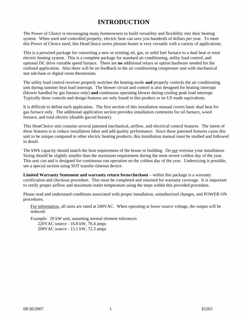
INTRODUCTION The Power of Choice is encouraging many homeowners to build versatility and flexibility into their heating system. When used and controlled properly, electric heat can save you hundreds of dollars per year. To meet this Power of Choice need, this HeatChoice series plenum heater is very versatile with a variety of applications. This is a prewired package for converting a new or existing oil, gas, or solid fuel furnace to a dual heat or total electric heating system. This is a complete package for standard air conditioning, utility load control, and optional DC drive variable speed furnace. There are no additional relays or option hardware needed for the outlined application. Also there will be no feedback to the air conditioning compressor unit with mechanical stat sub-base or digital room thermostats. The utility load control receiver properly switches the heating mode and properly controls the air conditioning unit during summer heat load interrupt. The blower circuit and control is also designed for heating interrupt (blower handled by gas furnace only) and continuous operating blower during cooling peak load interrupt. Typically these controls and design features are only found in this product or its US made equivalents. It is difficult to define each application. The first section of this installation manual covers basic dual heat for gas furnace only. The additional application section provides installation comments for oil furnace, wood furnace, and total electric (disable gas/oil burner). This HeatChoice unit contains several patented mechanical, airflow, and electrical control features. The intent of these features is to reduce installation labor and add quality performance. Since these patented features cause this unit to be unique compared to other electric heating products, this installation manual must be studied and followed in detail. The kWh capacity should match the heat requirement of the house or building. Do not oversize your installation. Sizing should be slightly smaller than the maximum requirement during the most severe coldest day of the year. This unit can and is designed for continuous run operation on the coldest day of the year. Undersizing is possible, see a special section using SOT transfer timeout device. Limited Warranty Statement and warranty return form/checkout – within this package is a warranty certification and checkout procedure. This must be completed and returned for warranty coverage. It is important to verify proper airflow and maximum outlet temperature using the steps within this provided procedure. Please read and understand conditions associated with proper installation, unauthorized changes, and POWER ON procedures.
For information, all units are rated at 240VAC. When operating at lower source voltage, the output will be reduced.
Example: 20 kW unit, assuming normal element tolerances 220VAC source - 16.8 kW, 76.4 amps 208VAC source - 15.1 kW, 72.3 amps
08/30/2007 2 EI203
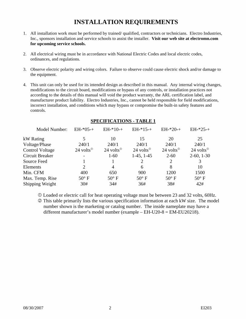
INSTALLATION REQUIREMENTS 1. All installation work must be performed by trained/ qualified, contractors or technicians. Electro Industries,
Inc., sponsors installation and service schools to assist the installer. Visit our web site at electromn.com for upcoming service schools.
2. All electrical wiring must be in accordance with National Electric Codes and local electric codes,
ordinances, and regulations. 3. Observe electric polarity and wiring colors. Failure to observe could cause electric shock and/or damage to
the equipment. 4. This unit can only be used for its intended design as described in this manual. Any internal wiring changes,
modifications to the circuit board, modifications or bypass of any controls, or installation practices not according to the details of this manual will void the product warranty, the ARL certification label, and manufacturer product liability. Electro Industries, Inc., cannot be held responsible for field modifications, incorrect installation, and conditions which may bypass or compromise the built-in safety features and controls.
SPECIFICATIONS - TABLE 1
Model Number: EH-*05-+ EH-*10-+ EH-*15-+ EH-*20-+ EH-*25-+
kW Rating 5 10 15 20 25 Voltage/Phase 240/1 240/1 240/1 240/1 240/1 Control Voltage 24 volts 24 volts 24 volts 24 volts 24 volts Circuit Breaker - 1-60 1-45, 1-45 2-60 2-60, 1-30 Source Feed 1 1 2 2 3 Elements 2 4 6 8 10 Min. CFM 400 650 900 1200 1500 Max. Temp. Rise 50° F 50° F 50° F 50° F 50° F Shipping Weight 30# 34# 36# 38# 42#
Loaded or electric call for heat operating voltage must be between 23 and 32 volts, 60Hz. This table primarily lists the various specification information at each kW size. The model number shown is the marketing or catalog number. The inside nameplate may have a different manufacturer’s model number (example – EH-U20-8 = EM-EU20218).

08/30/2007 3 EI203
MECHANICAL The HeatChoice is designed to control or compensate for certain airflow problems inherent with tight spacing residential forced air furnace systems. However, the HeatChoice cannot produce airflow and cannot correct airflow problems inherent within the existing furnace system. The following eight items should be carefully considered and properly followed for all installations: 1. EXAMINATION OF EXISTING FORCED AIR FURNACE - Prior to starting this installation or furnace
modification, examine the total furnace system and make necessary comments or recommendations to the homeowner. Remember, if a marginal condition exists within the existing forced air system, the installation of an HeatChoice will not necessarily cure PRE-EXISTING conditions. Consider such items as proper fossil fuel ignition, is the furnace cycling on hi-limit, filter, adequate cold air return, adequate supply duct and room register (1 register per 100 CFM) etc.
2. FURNACE TYPE – Determine UPFLOW or DOWNFLOW furnace type. You must use the correct model
for appropriate furnace type. The DOWNFLOW can be used in horizontal applications, follow instructions and install loose supplied sensor. Do not turn the HeatChoice upside down or install this unit in the cold air return.
3. HEATING CAPACITY - Size the HeatChoice according to the normal heating requirements as the building
exists today. Do not necessarily match to the existing furnace nameplate because it may be oversized. Do not oversize the HeatChoice.
4. SUPPLY PLENUM (this paragraph written primarily for UPFLOW; however, it also would apply to
various DOWNFLOW or horizontal applications) - Carefully examine all sides of the plenum. Visualize an ideal location for the HeatChoice and follow all the details of the appropriate installation diagram. Verify all transitions have angles less than 30°, the HeatChoice is centered within the plenum, and there are no odd shaped angles or odd shaped transitions within the plenum. One or more of the following will apply:
a. No A-Coil – follow drawing EA107, ignore the sketched in “A-coil”. Notice all distribution
ducts or pipes must be above HeatChoice elements with 1Ø" minimum clearance at top. If lots of height is available, center unit between furnace top and lowest take-off duct.
b. Air Conditioning A-Coil – follow Drawing EA107. The HeatChoice must be above A-coil and
parallel to A-coil. Again, all distribution ducts must be above the HeatChoice.
c. Width or DEPTH, 16” Furnace – where possible use 15” model. If using 18” model, build out both sides or back with a 30° transition. Do not build out the HeatChoice mounting front. The build-out should be as high as possible so that the elements do not set in a pocket.
NOTE: Do not use a 15" model in plenums larger than 18"x18". This is especially true when installing over an A-coil. The elements must be located at and close to the sides of the plenum.
d. Width or DEPTH greater than 19" – only use the 18" model and follow drawing EH101 (C-1
and C-2). Ideally all plenums should be built-in so that the HeatChoice is inserted into 19"x19" box. The mounting plate or control box of the HeatChoice must be flat with the existing plenum. If plenum is too wide, build-in must be on both sides, equally.
NOTE: Some plenums may require combinations such as a full vertical deflector, drawing EH1Ø1 (C-2) in the back and possibly a "V" deflector, EH1Ø1 (C-1) on each side.
e. Plenum access, hot objects – HeatChoice control box must be at least 12" from flue pipe or
other hot objects.

08/30/2007 4 EI203
5. OTHER PLENUM EQUIPMENT - Auxiliary equipment such as humidifiers, zone plenum dampers, etc., located within the plenum which may cause a non-uniform airflow will have to be removed. Zone dampers within the trunk line at least 12" from the HeatChoice typically are no problem. When horizontal zone dampers are involved, perform all check-out functions with smallest zone open first.
Comment – zone dampers cause back pressure on the blower and overall reduced airflow. The HeatChoice elements should be staged according to the heating load required by the various zone combinations. The Electro Industries’ WarmFlo series plenum heater is designed for zone systems and should be investigated for forced air zone applications.
6. AIR CONDITIONING “W” OR “M” COILS - These new coils represent a double “A” or an “A” with a
third slanted side. The net result is the top point no longer lines up with the center deflector of the HeatChoice frame. The only known solution is adequate space between the coil top and the HeatChoice unit itself. Also we have no direct experience to know how much space is required, we are suggesting a requirement of at least 12” between the top points of these new coils and the bottom of the HeatChoice frame itself.
7. INSUFFICIENT COLD AIR RETURN CAPACITY - Installation experience indicates this is a major
concern. In fact, it could represent a problem in as many as 6Ø% of the installations, especially if there is a requirement to increase airflow with the existing blower and the existing cold air return capacity is already undersized or restricted. Check the static pressure within the return cabinet or the suction at the filter cabinet door. Do not assume because there is a register on the wall, the hole behind the register or the passageways are equal to this register. Sharp offsets and transitions in the cold air return system often cause severe restrictions. Expect to add additional registers or a relief register in the main cold air return duct.
8. BLOWER CFM CAPACITY - The furnace forced air system must have an airflow capacity larger than the
minimum requirement on an HeatChoice specification sheet (see "SPECIFICATIONS - TABLE 1") or the HeatChoice nameplate. It is near impossible to correctly measure CFM airflow in an existing residential installation. Experience and rule of thumb indicators will have to be followed to determine the existing furnace CFM capacity. The following may be helpful:
a. Existing furnace nameplate - Typically represents a high or optimistic rating and is a function of
the systems static pressure. What changes have been made to the heating system since installation?
b. Blower motor size - Used only as a minimal guide.
10 kW unit - 1/4 HP or larger 15 kW unit - 1/3 HP or larger 20 kW unit - 1/2 HP or larger 25 kW unit - 3/4 HP or larger
c. Observe/examine airflow ducting system and design - Use duct sizing table (ECØØ1), or
industry equivalent duct capacity airflow charts and determine if the system is capable of delivering the CFM required on the nameplate. Especially check the number of registers and the number of “6 inch rounds”. The same would apply to cold air return duct capacity.
d. Calculated CFM - By measuring the temperature rise across the existing furnace (or this electric
unit), the CFM can be approximated. The accuracy of this formula will depend upon the estimated or determined Btu output (actual heat energy across the furnace).
CFM = Btuh (output) Temp. Rise x 1.08

08/30/2007 5 EI203
MECHANICAL INSTALLATION STEPS UPFLOW
NOTE: For maximum performance and maximum element life, this unit must be installed in the furnace hot air plenum such that there is uniform airflow across each element and maximum airflow across the entire element surfaces.
If all the previous two pages have been verified the actual installation involves the following steps: 1. Cutting the correct hole size in the plenum – locate the supplied cutout template marked “UAI012”. Once
placement of the HeatChoice is determined, tape all four corners of the template to the plenum. Make sure that the template is square with the plenum before proceeding to the next step. Using a utility knife cut out the appropriate dashed line on the template. Then use a marker to trace around the area cut out of the template. Remove the template from the plenum and proceed to cut the hole into the plenum.
2. Install the necessary deflectors or plenum build-in as outlined on previous page and as shown in C-1 and C-
2 on drawing EH101. 3. Use a light or flashlight to check the top of the furnace, around the furnace heat exchanger, position of the
A-coil, the cleanliness of the A-coil, and any conditions within the furnace system which would result in a non-uniform airflow at any of the electric elements.
4. If required, install plenum strengthening bars or S-clips. Verify there are no flanges or obstructions around
the opening to prevent air from entering the HeatChoice double plate air cooler. If vertical strengthening bars are used they must be placed on the inside surface of the plenum.
5. Extend the HeatChoice "V" channel to butt against the plenum back surface or the installed deflector
opposite the cut-in hole. After HeatChoice insertion, a sheet metal screw may be installed to attach the back plate of this “V” deflector channel.
6. When handling or inserting the actual HeatChoice unit, verify the element or the element fins do not become
bent and the sensor probe is parallel with the top element. This probe (blue end) must be approximately center between top element and 1½" from element fin. The capillary tube should have an upward angle.
7. Insert the HeatChoice unit with the sensor probe at the top or above the element by hooking in the bottom
mounting plate first. This should catch the bottom of the plenum hole opening and hold in place while starting the top screws (observe airflow arrow inside control box).
8. Verify that there is a tight air seal around the complete HeatChoice unit and there are no obstructions for
airflow into the double plate cooling chamber.
NOTE: If the mechanical contractor has responsibility for this job (sold the unit), he must return to perform the POWER ON start-up test and fill out the warranty certification data sheet. The job is not complete until there is thorough verification of proper operation.

08/30/2007 6 EI203
MECHANICAL INSTALLATION STEPS DOWNFLOW
NOTE: Please refer to drawing EA104, revision E or newer for proper placement of the HeatChoice unit when an A/C coil is installed.
1. If the DOWNFLOW furnace is setting directly on the floor, the furnace will have to be raised for insertion of the HeatChoice unit. This will require a field designed and constructed plenum. This plenum must have sufficient strength to carry the weight of the existing furnace.
2. Depending upon model, the ideal plenum size for the HeatChoice is either 15” x 18” or 18”x18”. Therefore,
this base plenum should be sized according to the HeatChoice and the hot air discharge hole on the bottom of the furnace. It should NOT be sized according to the outer dimensions of the furnace (see drawing EA1Ø4).
3. Examine the hot air discharge hole in the bottom of the downflow furnace. Assuming 18” model, if it ranges
between 18”x18” to 19”x19” (if 15” model adjust accordingly) the HeatChoice unit can be installed directly beneath the furnace if there is no A/C coil installed. This plenum need only be about 11” high. If the bottom hot air discharge hole is less than 18”x18”, use 15” model or allow at least 6” between the bottom of the furnace and the top of the HeatChoice unit (see drawing EA1Ø4).
4. The HeatChoice is designed with a special double plate at the element mounting. Cool air from the bower
must blow between these two plates. Therefore, the Elector-Mate must be inserted into the base plenum such that the mounting plate is even with the edge of the hot air outlet hole. Do not necessarily line up the HeatChoice control box with the furnace cabinet front. The concern is the hole in the bottom of the furnace mating with HeatChoice elements.
5. Cutting the correct hole size in the plenum – locate the supplied cutout template marked “UAI012”. Once
placement of the HeatChoice is determined, tape all four corners of the template to the plenum. Make sure that the template is squared off to the plenum before proceeding to the next step. Using a utility knife cut out the appropriate dashed line on the template. Then use a marker to trace around the area cut out of the template. Remove the template from the plenum and proceed to cut the hole into the plenum.
6. Extend the “V” channel to butt against the plenum surface opposite the 8”x18” hole. After HeatChoice
insertion, a sheet metal screw may be installed to attach the back plate of this “V” deflector channel. 7. Insert the HeatChoice and properly screw to base plenum. If the base plenum is 15” or 18” wide, side
supports will be needed on the side for proper attachment to the HeatChoice. 8. When using A-coil with a bottom discharge furnace note the vertical spacing requirements on drawing
EA104. Allow as much separation as possible between HeatChoice unit and A-coil drip pan.
Also encourage using the 15” model and add baffle constructed as shown on drawing EH101.

08/30/2007 7 EI203
MECHANICAL INSTALLATION STEPS HORIZONTAL
1. Basically this involves a downflow unit (EH-D***) turned 9Ø° with the plenum instruction and rules
common to the upflow unit. 2. The key is to observe the “AIRFLOW” arrow and allowing for gravity temperature rise, making sure there
is a probability for the hi-limits sensing at an upper point in case of airflow failure. Also, all airflow must pass uniformly through the elements. Feel free to call the factory for additional assistance with horizontal applications.
3. A majority of the items reviewed on pages 3 and 4 apply. 4. Reference previous page 3 and paragraph 4, all requirements for plenum sizing and deflectors apply. This
installation could represent a 15” model or an 18” model, again apply the rules outlined on page 3. 5. Air conditioning coil, typically we are aware of three physical coil types – flat (90° to horizontal duct), slant
coil, and A-coil turned 90° (with an extended drip pan at the bottom). With these three types, the HeatChoice is typically installed after the coil or on the “supply” side. Again top and bottom and backside deflectors may be required depending upon plenum size.
- Flat coil – allow at least 8 inches between coil and HeatChoice. - Slant coil – installing the HeatChoice at the same angle as the coil is preferred, or insert the
HeatChoice as close as possible to the horizontal plenum bottom (assuming this is the furthest distance between coil and HeatChoice).
- Turned A-coil – similar to an upflow, the HeatChoice must be inserted in line with the A-coil, with the HeatChoice deflector centered on the inverted “A” and as close as possible to the coil inverted A “top”.
6. Cut the HeatChoice insert hole into the plenum at the predetermined location. The size of this hole will
depend upon the HeatChoice model. The last digit of the model number indicates the width. 15” model - 8”x15 ¼” hole 18” model - 8”x18 ¼” hole
7. When handling or inserting the actual HeatChoice unit, verify the element or the element fins do not become
bent and the sensor probe is parallel with the top element. These probes must be approximately 1½” from element fin.
8. Extend the “V” channel to butt against the plenum surface opposite the insert hole. 9. Insert the HeatChoice unit making sure the center deflector has its point toward the furnace. Verify that the
unit is completely inserted so the air will flow between the element mounting plate and the front panel. Mount the unit to the plenum.
10. Verify that there is a tight air seal around the HeatChoice off-peak conversion unit and the plenum. Verify
that the unit is rigidly supported and there is no vibration when the blower motor is operating.
Note: If the mechanical contractor has responsibility for this job (sold the unit), he must return to perform the POWER ON start-up test and fill out the certification data sheet. The job is not complete until there is a thorough verification of proper operation.

08/30/2007 8 EI203
ELECTRICAL HOOKUP
Note: All heat/cool functions for this dual heat system originate from a standard 4-wire (heat/cool) room thermostat. Do not install with a 2-stage heat/1-stage cool or a heat pump room thermostat. Also do not install using two individual thermostats.
1. 24Ø VOLT SOURCE - Route and wire from the appropriate service entrance panel directly to the
HeatChoice circuit breakers, use only copper connected to breakers. The service entrance disconnect and 24Ø volt wire shall be sized according to the HeatChoice nameplate rating. The circuit breakers within this unit qualify as the appropriate local disconnect.
- If using single-feed wiring (15 or 20 kW), optional CB bus bars are available, order EM-5716 (25 kW, EM-5717).
2. GROUNDING - Route and install the appropriate size conductor wire between the HeatChoice lug labeled
"ground" and the building service entrance panel ground bus. Use NEC code requirements for grounding wire size. The conduit is not a sufficient ground conductor.
3. CONTROL WIRING (reference schematic ES201) – The section assumes gas furnace has an appropriate
fan center or appropriate equivalent wiring terminals with 40VA or larger integral transformer and blower relay with “G” function.
a. Room thermostat – use only basic 4-wire, heat/cool type. Route the standard R, W, G, Y roomstat screw functions to the HeatChoice DHC control board top tab/screw terminal adapters. Use wire to wire same letter connection.
b. Air conditioning, outdoor unit – this should be a 2-wire hookup, typically represents the contactor coil. Connect one wire to the top “Y2” terminal and the second to a bottom “C” terminal.
c. Gas (or oil with fan center) furnace – the furnace should have a 4 or 5-wire terminal block and match the control board bottom four terminals – R, W, G, C.
- The furnace may also contain a “Y” screw, this is only needed if it is a variable speed (DC

08/30/2007 9 EI203
drive) furnace, see next section. - Depending upon furnace manufacturer, the common may have various letter terminology –
C, B, X. “C” is 24-volt common for this product. d. Utility load control – extend the two blue wires to an appropriate set of wires or contact closure
within the power company control receiver. For electric energy operation (off-peak) the two blue wires represent a contact closure as shipped. Do not apply external voltage or external power to the blue wires, they are simply looking for a closed contact during off-peak.
- Optional – where load management interrupt does not apply simply leave the two blue wires tied together and wire nutted.
- If load control reverse logic is required, call factory. 4. BLOWER CONTROL – this is handled within the 4 (or 5) wire connection between the DHC control board
bottom and the gas furnace hookup. The HeatChoice DHC control board allows the blower to turn off and operate under the control of the gas furnace during standby or utility interrupt. During cooling the DHC logic keeps the blower running during utility air conditioning interrupt to circulate summer air.
a. Delay on/off – within the DHC logic, the blower turns on with an approximately 10 second delay. At the end of the thermostat heat cycle, the blower must continue to operate for at least 30 seconds to cool off the HeatChoice metal rod electric elements.
b. Purge cycles – effective version 2-03-05, there is a 1-minute delay before allowing a gas furnace W input in order to allow the furnace blower to cool off the HeatChoice elements. Also there is a built-in delay before turning on the electric elements after the gas furnace has been on.
c. Thermostat “G” function – do not connect the thermostat G wire directly to the gas furnace G screw. The thermostat G wire must pass through the HeatChoice DHC module from top point to the bottom point.
5. DOWNFLOW OR HORIZONTAL ONLY - HI-LIMIT PROBE EM5714 (shipped loose in control box cabinet) – Install probe as close as possible below Electro-Mate on the right side, see drawing EA104. Within the upper right portion of the main control box locate one of the two wire nuts that join a red wire from the right hi-limit probe to a red/white wire from the DFC wire harness, see drawing ES201. Remove wire nut, route, and connect in series to this additional hi-limit probe’s red wires.
POWER ON, STARTUP
1. Use the airflow verification procedure within the attached warranty certification form. If you experience hi-limit cycling or plenum temperatures greater than specified, this must be corrected before leaving the site. Correction can include verification of proper placement within the plenum, plenum deflectors/baffles (previous diagrams), increasing overall furnace airflow capacity, enlarging furnace blower, or disconnecting lower elements to reduce the heating capacity. To disconnect elements, simply remove (starting with lower left element) the element wire going to the hi-limit. Tape off and protect both the element end and the removed wire.
2. Using general heating and utility load control experience, cycle the HeatChoice with the roomstat and load control receiver functions.
- The blower must come on within 30 seconds and the blower will continue approximately 1 minute after termination of the heat cycle. The blower function from the HeatChoice will also terminate during load control. It is expected the gas furnace will do its own blower control during standby.
3. Check blower current, compare to nameplate reading and verify blower motor is not being overloaded.
4. Complete the warranty certification form and return to Electro Industries, address or fax shown.
5. Recheck all electrical connections and screws for tightness, including factory wiring.

08/30/2007 10 EI203
OPERATIONAL TIPS
1. MANUAL HI-LIMIT RESET – Located behind the hinged control board door is a 250°F manual reset. This breaks the circuit for all electric elements. However, connected in the same circuit loop is the automatic reset 170°F hi-limit. Normally the automatic reset should always take care of any overheat condition prior to popping the manual reset. Therefore, you should not experience a manual reset condition unless there has been a true hardware failure.
Two exceptions – a standby furnace (or wood furnace) having an outlet temperature greater than 250°F or cold startup without blower. Because of the sensitivity of this capillary manual reset, anytime there is a blower failure when the elements come on you can expect a manual reset.
2. The front panel normal/standby switch allows the user to condition the system to select energy source. This
can be used for repair or troubleshooting of the furnace or simply “Power of Choice” selection. 3. DHC module indicators
Front panel amber LED – illuminates during electric heating mode. Green LED (inside, next to fuse) – indicates 24-volt source from furnace and non-blown fuse. Red LED (inside top) – room thermostat call for heat. Amber LED (inside, next to connect/harness) – illuminated when load management receiver is in electric or off-peak mode. Red LED (inside bottom) – gas furnace W is receiving 24V. Red LED (inside left, next to HL red/wht wires) – 160° hi-limit is open.
NOTE: The DHC control module contains a 2 amp fuse. Use AGS-2 or equivalent (UFUSE0440) for replacement.
4. BLOWER RESPONSE - The blower has an approximate 15 second turn-on delay and will continue from 45
seconds to one minute after electric element power is turned off via the room thermostat. This is necessary to properly cool off the elements.
5. SYSTEM TEMPERATURE RISE - The overall temperature rise (both sides of HeatChoice) must be within
the maximum specification, see "SPECIFICATIONS - TABLE 1". If any portion of the plenum (above elements) is operating with an air temperature greater than 125°F, element life will be shortened.
- CFM CALCULATIONS, THIS HEATCHOICE - By measuring the temperature rise across the HeatChoice, the actual CFM can be quite accurately determined. If you are having difficulty sustaining hi-limit operation, it may be a good idea to calculate the CFM according to this formula. To arrive at a stable output temperature, you can turn off CB #2 and operate only as stage one. This will allow you to verify or calculate the CFM without reaching hi-limit cycling. The accuracy of this formula will depend upon uniform and average temperature rise plenum thermometer readings and the accuracy of both the clamp-on amp meter and AC voltmeter. NOTE: The volts x amps x 3.4 value is the same as Btuh output.
Volts x Amps x 3.4 CFM = Temperature Rise x 1.08
- CALCULATED CFM, OIL/GAS FURNACE - By measuring the temperature rise across the existing furnace, the CFM can be approximated. The accuracy of this formula will depend upon the estimated or determined Btuh output (actual heat energy across the furnace). You cannot use nameplate Btuh values. You must use a realistic estimated or measured true OUTPUT Btuh.
Btuh (output) CFM = Temperature Rise x 1.08

08/30/2007 11 EI203
6. SPECIAL STANDBY FURNACE AND CERTAIN PLENUM WIDTH CONDITIONS - As we continue
gathering installation experience, we are seeing several over temperature situations reoccurring. The intent of this paragraph is to provide additional help for four specific plenum conditions:
a. Large burner pot oil furnace with the HeatChoice installed less than about 6" from the top of the
heat exchanger/fire pot. - Install from either the back or front (inline with the flue or burner)
b. HeatChoice installed from either side of an oil furnace. - Locate as high as possible above the oil furnace, but realizing elements need to be inline
or below take off ducts c. Plenums width between 19" and 2ؽ"" without the use of side deflectors.
- Add deflectors per drawing EH101, C-1 d. HeatChoice installed above an A-coil where the HeatChoice sits directly on top of the A-coil
without side deflectors. - Add deflectors per drawing EH101, C-1
ADDITIONAL APPLICATIONS
Oil furnace – isolation contacts are required at oil burner control “T and T” and terminals. If you do not have a fan center with proper isolated contact closure for “T and T”, you must add a relay as shown.
Furnace variable speed blower – a fifth wire connection may be needed to speed up the gas furnace blower for air conditioning and HeatChoice electric heating operation. Add jumper and the fifth wire to the gas furnace “Y” terminal as shown on the diagram.
Note: Connection wires shown are in addition to 4-wire thermostat and 4 wires to furnace.
Load Control, other Electro products – on HeatChoice control board, bottom right, connect blues to COM and EL.
EI20302-18-03
F2
LED2
SW1
Y2T12
T18
YT11
STATG
T13WT2
RT1
LED1J1
NO
BLT16
T17
NC
COMT20
T15
K3K1
EL
SB
T22
T21
W2
A
W1
K5
COM
C
T8
CS
LED3
UPCB5626
T7CG
T14
T19
OFF
LED6
3
HL
PEAK
T10
T3
LED4
ONPWR
LED5
F1
T4 HL
24 VAC
R RT6T5 T9
WFAN CENTER
K2 K4 A/CCONDENSER
FURNACE"Y"
Y2
C
Y2
NO
NCBL
W

08/30/2007 12 EI203
2-stage or variable burner gas – most furnaces ignore or do not take W2 (or Rhuud “V”) action unless there is an input to W1. This means you can take a wire directly from 2-stage heat roomstat W2 to the furnace W2 and until the system is switched over to standby with the HeatChoice control board activating W1 there should be no furnace action. 2-speed or 2-stage air conditioning – load control action may be required with the outdoor unit Y2. This can be accomplished by routing the roomstat Y2 through a relay contact (onboard tabs) and the outdoor unit Y2.
- Roomstat Y2 – COM - EL – outdoor unit Y2
Wood furnace – inlet air sensor required, must order and install EM5713 sensor for all non-automatic standby applications, reference drawing EH017. The heated air coming off of the wood furnace must be less than about 90° before the electric elements will activate. Large mass furnace heat exchanger, oil, etc. – if there was an active standby heat call during the release of a load control back to electric, the heat build-up within the heat exchanger and the heating up of electric elements may initially produce an output temperature which exceeds the manual reset (250°). Normal tubular gas furnace heat exchanger should not be a problem because the electric element initial temperature delay is approximately 45 seconds. Adding EM5713 inlet air sensor (reference drawing EH017) between the heat exchanger and the HeatChoice unit will keep the electric elements off until the blower brings the heat exchanger down to approximately 90°. Fault sensor or automatic switchover, option – a plug-in option, SOT-1, provides the standard 80-minute adjustable SOT and an interface relay with the necessary hookup drawing. This small plug-in device can automatically switch to standby furnace if there is a system fault associated with inadvertent circuit breaker, manual reset hi-limit, etc. If the HeatChoice unit is undersized (intentionally or unknown) this plug-in option will also automatically switch to standby heating if the HeatChoice electric unit cannot maintain temperature set point. Remote emergency or override switch – a simple toggle switch can easily be remotely located and connected between the tabs marked “SB” and “C”. When this remote switch is closed, the system reverts to standby heating. Total electric – in this case there probably is no utility load control receiver, simply keep the two blue wires shorted with wire nut and the furnace burner is probably disabled. The furnace is only used as a blower source. The 240 element power probably comes from the appropriate size CB breakers within the general service panel. Time-of-Use or Time-of-Day – installation is basically the same as the previous dual heat/load management concept, except the 240 power source probably comes from CB’s within the single general service panel. The control for the blue wires can be an internal contact within the TOU meter or a user provided time clock with its time function coincident with the TOU on/off-peak time.
Note 1: When using an external time clock make sure the blue wires go to an isolated contact and make sure the time clock is not inadvertently providing line voltage to one of the blue wires. Line voltage will result in instant circuit board failure. Note 2: Some TOU or limited off-peak internal control contacts (Xcel, Wisconsin) have N.O. = off-peak logic. In this case use an interposing relay to reverse logic (order EE5053). Application drawing AA009 provides this hookup.
Heat pump – this HeatChoice DHC control board has no provisions for heat pump operation or wiring. Typically if there is a heat pump involved with this system, this is the wrong plenum heater product. Contact factory or your local distributor for information on other models that include heat pump intelligent systems.
OFFSET TAKEOFF CAN BE3" BELOW EM TOP CUTOUTELECTRO-MATE
EM-WU***EM-LV***
MODEL SERIES:REFERENCE
10" MINIMUM FROMTOP OF EM CUTOUT Duct
Dist.
DuctDist.
CORNER MUST BEEM TOP CUTOUT
A-Coil
Upflow Only
1
5
4
2
6
3
7
8
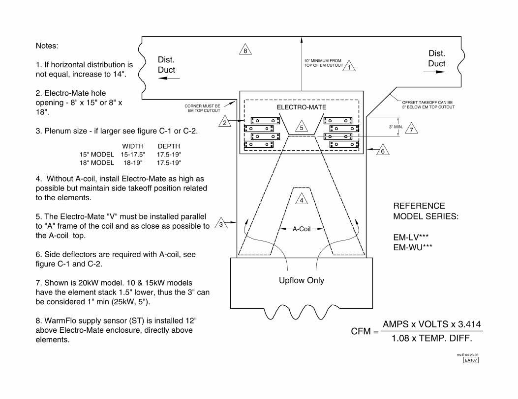
15-17.5"18-19"
WIDTH
AMPS x VOLTS x 3.414CFM =
1.08 x TEMP. DIFF.
17.5-19"17.5-19"
DEPTH15" MODEL18" MODEL
4. Without A-coil, install Electro-Mate as high as possible but maintain side takeoff position related to the elements.
5. The Electro-Mate "V" must be installed parallel to "A" frame of the coil and as close as possible to the A-coil top.
6. Side deflectors are required with A-coil, see figure C-1 and C-2.
7. Shown is 20kW model. 10 & 15kW models have the element stack 1.5" lower, thus the 3" can be considered 1" min (25kW, 5").
8. WarmFlo supply sensor (ST) is installed 12" above Electro-Mate enclosure, directly above elements.
Notes:
1. If horizontal distribution is not equal, increase to 14".
2. Electro-Mate hole opening - 8" x 15" or 8" x 18".
3. Plenum size - if larger see figure C-1 or C-2.3" MIN.
EA107rev.E 04-23-03


DIAGRAM, EH-*25-*WIRING SCHEMATIC
DESCRIPTIONELECTRO INDUSTRIES, INC.
MONTICELLO, MN 55362
DRAWN REFERENCE DOCUMENT
PART/ASSY/MODEL NUMBERSCALEVIEW/DRAWING TYPECHECKED
DRAWING STATUS DOCUMENT NUMBERSHEETDOCUMENT DATEAPPROVED
ES201
EH-***-*WIRING SCHEMATIC
1/503-14-03
NTS
RELEASED
EH104MEF
EH-D25-8
EH-U25-8
T#
HL#
K#
###°
K# K#
E#
CB#
TAB (CIRCUIT BOARD)
CIRCUIT BREAKER
SYMBOL LEGEND
HI-LIMIT (NC)
RELAY (COIL)
RELAY (CONTACTS)
ELEMENT
REV
ISED
-A10-19-05
Rev.A 10-19-05: Updated hi-limit temperature values.
3
LMC K1 K2GRAY
T5
R
170°
HL7
250°
HL6RED
GRAY
BLU/WHT
ORG/BLK
RED/WHT
RED/WHT
K3
RED
RED
6
T4
T3
T10
6
WHT/BLU
GRAY
BLUE
3
5
2
ORANGE
TO J1
1
3
5
2
1
J1
BLACK
BLACK
BLACK
BLACK
E2
E4
E1
E5
RED
CB1
60A
L1 L2
BLACK
K1-2
118°
BLACK
RED
BLACKHL1
BLACK
K1-1
BLACK
BLACK
L1
BLACK
CB2
60A
L2
RED
K2-2
118°
BLACK
BLACK
BLACKHL4
RED
K2-1
BLACKHL2
118°
BLACKHL3
118°
E8BLACK
E6BLACK
L1
CB3
30A
L2
RED
E7BLACK
E3BLACK
RED
BLACK
BLACK
K3-2 E10BLACK
BLACK
K3-1
HL5
118°
E9BLACK
FAN CENTER
CONNECTION
T6 T14T9 T7
R W G C
DHC@EMDHC5626
T8
C
T19
A
SB
HL
T21
T22
EL
COM
T20
T15
NC
BL
T2
R
T1
GW
T11
T16
T17
NO
T18
T12
Y2Y
T13
T-STAT
CONNECTION
HL8
170°
DOWNFLOW ONLY
RED/WHTRED

DIAGRAM, EH-*20-*WIRING SCHEMATIC
DESCRIPTIONELECTRO INDUSTRIES, INC.
MONTICELLO, MN 55362
DRAWN REFERENCE DOCUMENT
PART/ASSY/MODEL NUMBERSCALEVIEW/DRAWING TYPECHECKED
DRAWING STATUS DOCUMENT NUMBERSHEETDOCUMENT DATEAPPROVED
ES201
EH-***-*WIRING SCHEMATIC
2/503-14-03
NTS
RELEASED
EH104MEF
EH-D20-5
EH-D20-8
EH-U20-5
EH-U20-8
T#
HL#
K#
###°
K# K#
E#
CB#
TAB (CIRCUIT BOARD)
CIRCUIT BREAKER
SYMBOL LEGEND
HI-LIMIT (NC)
RELAY (COIL)
RELAY (CONTACTS)
ELEMENT
REV
ISED
-A10-19-05
Rev.A 10-19-05: Updated hi-limit temperature values.
T-STAT
CONNECTION
T4
T3
6
3
5
2
J1
1
T10
R
T1 T2
W
T11
G Y
T13
Y2
T12
T18
T17
T16
T15
T20
T21
T22
T19
3
NO
BL
NC
COM
EL
SB
A
T5
R R
T6
W
T9
G
T14
C
T7
C
T8
FAN CENTER
CONNECTION
RED
250°
HL5
170°
RED
HL6RED
RED/WHT
RED/WHT
CB2
60A
K1LMC
CB1
60A
L1 L2
BLACKBLACK
E5
L1 L2
K2
ORANGE
BLUE
BLU/WHT6
5
GRAY
WHT/BLU
3
1
2
TO J1
BLACK BLACK
E8
HL3HL2BLACK
RED
BLACK
RED
K1-2
RED
HL1BLACK
118°
BLACK
E1BLACK
K1-1
RED
BLACK
118°
E2BLACK
BLACKBLACK
E4
BLACK
BLACK
K2-2 E6BLACK
HL4
118°
E3K2-1
BLACK
BLACK
E7BLACK
BLACK
118°
HL
@EMDHC5626
DHCRED/WHT
DOWNFLOW ONLY
HL7
170°
RED

DIAGRAM, EH-*15-*WIRING SCHEMATIC
DESCRIPTIONELECTRO INDUSTRIES, INC.
MONTICELLO, MN 55362
DRAWN REFERENCE DOCUMENT
PART/ASSY/MODEL NUMBERSCALEVIEW/DRAWING TYPECHECKED
DRAWING STATUS DOCUMENT NUMBERSHEETDOCUMENT DATEAPPROVED
ES201
EH-***-*WIRING SCHEMATIC
3/503-14-03
NTS
RELEASED
EH104MEF
EH-D15-5
EH-D15-8
EH-U15-5
EH-U15-8
HL#
RELAY (CONTACTS)
TAB (CIRCUIT BOARD)
K#
T#
RELAY (COIL)
HI-LIMIT (NC)###°
K# K#
SYMBOL LEGEND
CIRCUIT BREAKER
ELEMENTE#
CB#
REV
ISED
-A10-19-05
Rev.A 10-19-05: Updated hi-limit temperature values.
L1
CB1
45A
L2
CB2
45A
L1 L2
HL2
RED
K1-2 E1BLACK BLACK
HL1BLACK
118°
E2K1-1
RED
BLACK
E4BLACK
BLACK BLACK
BLACK
118°
HL3
E6RED BLACK
K2-2
BLACKHL4
118°
BLACK
E3K2-1
RED BLACK
BLACK
118°
BLACK
DHC
FAN CENTER
CONNECTION
R R GW CC
@EMDHC5626
T5 T6 T9 T14 T8T7
T10
T4HL
T3
3
6
5
3
2
1
RJ1 W
T1 T2
YG Y2
T13T11 T12
T-STAT
CONNECTION
250°
HL5RED
RED
170°
HL6RED
A
SB
T19
T21
T22
EL
COM
T20
T16
T15
NC
BL
NO
T17
T18
RED/WHT
RED/WHT
DOWNFLOW ONLY
RED/WHT
HL7
170°
RED
K2LMC K1
BLUE
BLU/WHT
5
6
WHT/BLU
GRAY
ORANGE
2
3
1
TO J1
E5BLACK BLACK

DIAGRAM, EH-*10-*WIRING SCHEMATIC
DESCRIPTIONELECTRO INDUSTRIES, INC.
MONTICELLO, MN 55362
DRAWN REFERENCE DOCUMENT
PART/ASSY/MODEL NUMBERSCALEVIEW/DRAWING TYPECHECKED
DRAWING STATUS DOCUMENT NUMBERSHEETDOCUMENT DATEAPPROVED
ES201
EH-***-*WIRING SCHEMATIC
4/503-14-03
NTS
RELEASED
EH104MEF
EH-D10-5
EH-D10-8
EH-U10-5
EH-U10-8
K# RELAY (COIL)
TERMINAL BLOCK
TAB (CIRCUIT BOARD)
21
TB#
T#
SYMBOL LEGEND
ELEMENT
RELAY (CONTACTS)K# K#
E#
REV
ISED
-A10-19-05
Rev.A 10-19-05: Updated hi-limit temperature values.
L1
LMC K1ORANGE
GRAY
BLUE
BLU/WHT6
5
3
1
L2
E3BLACK BLACK
TO J1
HL2
RED
K1-2 E1BLACK BLACK
HL1BLACK
118°
E2K1-1
RED
E4BLACK BLACK
BLACK BLACK
BLACK
118°
DHC
FAN CENTER
CONNECTION
R R GW CC
@EMDHC5626
T5 T6 T9 T14 T8T7
T10
T4HL
T3
3
6
5
3
1
RJ1
W
T1 T2
YG Y2
T13T11 T12
T-STAT
CONNECTION
250°
HL3RED
RED
170°
HL4RED
A
SB
T19
T21
T22
EL
COM
T20
T16
T15
NC
BL
NO
T17
T18
21
RED/WHT
RED/WHT
RED/WHT
DOWNFLOW ONLY
HL5
170°
RED
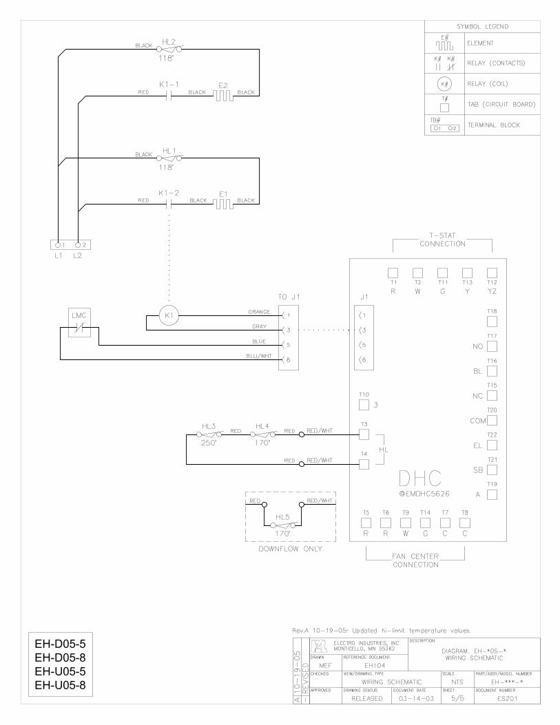
DIAGRAM, EH-*05-*WIRING SCHEMATIC
DESCRIPTIONELECTRO INDUSTRIES, INC.
MONTICELLO, MN 55362
DRAWN REFERENCE DOCUMENT
PART/ASSY/MODEL NUMBERSCALEVIEW/DRAWING TYPECHECKED
DRAWING STATUS DOCUMENT NUMBERSHEETDOCUMENT DATEAPPROVED
ES201
EH-***-*WIRING SCHEMATIC
5/503-14-03
NTS
RELEASED
EH104MEF
EH-D05-5
EH-D05-8
EH-U05-5
EH-U05-8
K# RELAY (COIL)
TERMINAL BLOCK
TAB (CIRCUIT BOARD)
21
TB#
T#
SYMBOL LEGEND
ELEMENT
RELAY (CONTACTS)K# K#
E#
REV
ISED
-A10-19-05
Rev.A 10-19-05: Updated hi-limit temperature values.
RED
BLACK
BLACK
250°
HL3
LMC K1
L2
21
L1
RED
K1-2
118°
BLACKHL1
RED
K1-1
BLACKHL2
118°
FAN CENTER
CONNECTION
T14
@EMDHC5626
DHC
T9T6T5
R R W G
T8T7
CC
A
SB
T19
BLU/WHT
170°
HL4
RED
RED
6
BLUE
GRAY
ORANGE
5
3
TO J1
1
T4HL
T3
T10
3
6
EL
T21
COM
T22
NC
T20
BL
T15
5
3
J1
1
WR
T1 T2
NO
T16
T17
Y
T13
G
T11
Y2
T18
T12
E1BLACK
E2BLACK
T-STAT
CONNECTION
RED/WHT
RED/WHT
RED/WHT
DOWNFLOW ONLY
HL5
170°
RED

Page 1 of 2 XX017
Electro Industries, Inc. Limited Product Warranty
Effective October 1, 2007 Electro Industries, Inc. warrants to the original owner, at the original installation site, for a period of two (2) years from date of installation, that the product and product parts manufactured by Electro Industries are free from manufacturing defects in materials and workmanship, when used under normal conditions and when such product has not been modified or changed in any manner after leaving the plant of Electro Industries. If any product or product parts manufactured by Electro Industries are found to have manufacturing defects in materials or workmanship, such will be repaired or replaced by Electro Industries. Electro Industries shall have the opportunity to directly, or through its authorized representative, examine and inspect the alleged defective product or product parts. Electro Industries may request that the materials be returned to Electro Industries at the owner’s expense for factory inspection. The determination as to whether product or product parts shall be repaired, or in the alternative replaced, shall be made by Electro Industries or its authorized representative. Electro Industries will cover reasonable labor costs to repair defective product or product parts for ninety (90) days after installation. TWENTY YEAR (20) LIMITED WARRANTY ON BOILER ELEMENTS AND VESSELS Electro Industries, Inc. warrants that the boiler elements and vessels of its products are free from defects in materials and workmanship through the twentieth year following date of installation. If any boiler elements or vessels are found to have a manufacturing defect in materials or workmanship, Electro Industries will replace them. TWENTY YEAR (20) LIMITED WARRANTY ON SPIN FIN ELEMENTS Electro Industries, Inc. warrants that the spin fin elements of its products are free from defects in materials and workmanship through the twentieth year following date of installation. If any spin fin elements are found to have a manufacturing defect in materials or workmanship, Electro Industries will replace them. FIVE YEAR (5) LIMITED WARRANTY ON OPEN WIRE ELEMENTS Electro Industries, Inc. warrants that the open wire elements of its products are free from defects in materials and workmanship through the fifth year following date of installation. If any open wire elements are found to have a manufacturing defect in materials or workmanship, Electro Industries will replace them.

Page 2 of 2 XX017
THESE WARRANTIES DO NOT COVER: 1. Costs for labor for removal and reinstallation of an alleged defective product or product parts,
transportation to Electro Industries, and any other materials necessary to perform the exchange, except as stated in this warranty. Replacement material will be invoiced to the distributor in the usual manner and will be subject to adjustment upon verification of defect.
2. Any product that has been damaged as a result of being improperly serviced or operated, including, but not limited to, the following: operated with insufficient water or airflow, allowed to freeze, subjected to flood conditions, subjected to improper voltages or power supplies, operated with airflow or water conditions and/or fuels or additives which cause unusual deposits or corrosion in or on the product, chemical or galvanic erosion, improper maintenance or subject to any other abuse or negligence.
3. Any product that has been damaged as a result of natural disasters, including, but not limited to, the following: lightning, fire, earthquake, hurricanes, tornadoes or floods.
4. Any product that has been damaged as a result of shipment or handling by the freight carrier. It is the receiver’s responsibility to claim and process freight damage with the carrier.
5. Any product that has been defaced, abused, or suffered unusual wear and tear as determined by Electro Industries or its authorized representative.
6. Workmanship of any installer of the product. This warranty does not assume any liability of any nature for unsatisfactory performance caused by improper installation.
7. Transportation charges for any replacement part or component, service calls, normal maintenance; replacement of fuses, filters, refrigerant, etc.
CONDITIONS AND LIMITATIONS: 1. If at the time of a request for service the original owner cannot provide an original sales receipt or a
warranty card registration then the warranty period for the product will have deemed to begin thirty (30) days after the date of manufacture and NOT the date of installation.
2. The product must have been sold and installed by a licensed electrical contractor, a licensed plumbing contractor, or a licensed heating contractor.
3. The application and installation of the product must be in compliance with Electro Industries’ specifications as stated in the installation and instruction manual, and all state and federal codes and statutes. If not, the warranty will be null and void.
4. The purchaser shall have maintained the product in accordance with the manual that accompanies the unit. Annually, a qualified and licensed contractor must inspect the product to assure it is in proper working condition.
5. All related heating components must be maintained in good operating condition. 6. All lines must be checked to confirm that all condensation drains properly from the unit. 7. Replacement of a product or product part under this limited warranty does not extend the warranty
term or period. 8. Before warranty claims will be honored, Electro Industries shall have the opportunity to directly, or
through its authorized representative, examine and inspect the alleged defective product or product parts. Remedies under this warranty are limited to repairing or replacing alleged defective product or product parts. The decision whether to repair or, in the alternative replace, products or product parts shall be made by Electro Industries or its authorized representative.
THESE WARRANTIES DO NOT EXTEND TO ANYONE EXCEPT THE ORIGINAL PURCHASER AT RETAIL AND ONLY WHEN THE PRODUCT IS IN THE ORIGINAL INSTALLATION SITE. THE REMEDIES SET FORTH HEREIN ARE EXCLUSIVE. ALL IMPLIED WARRANTIES, INCLUDING WARRANTIES OF MERCHANTABILITY AND FITNESS FOR A PARTICULAR PURPOSE, ARE HEREBY DISCLAIMED WITH RESPECT TO ALL PURCHASERS OR OWNERS. ELECTRO INDUSTRIES, INC. IS NOT BOUND BY PROMISES MADE BY OTHERS BEYOND THE TERMS OF THESE WARRANTIES. FAILURE TO RETURN THE WARRANTY CARD SHALL HAVE NO EFFECT ON THE DISCLAIMER OF THESE IMPLIED WARRANTIES. ALL EXPRESS WARRANTIES SHALL BE LIMITED TO THE DURATION OF THIS EXPRESS LIMITED WARRANTIES SET FORTH HEREIN AND EXCLUDE ANY LIABILITY FOR CONSEQUENTIAL OR INCIDENTAL DAMAGES RESULTING FROM THE BREACH THEREOF. SOME STATES DO NOT ALLOW THE EXCLUSION OR LIMITATION OF INCIDENTAL OR CONSEQUENTIAL DAMAGES, SO THE ABOVE LIMITATIONS OR EXCLUSIONS MAY NOT APPLY. PRODUCTS OR PARTS OF OTHER MANUFACTURERS ATTACHED ARE SPECIFICALLY EXCLUDED FROM THE WARRANTY. THIS WARRANTY GIVES YOU SPECIFIC LEGAL RIGHTS, AND YOU MAY HAVE OTHER RIGHTS WHICH VARY UNDER THE LAWS OF EACH STATE. IF ANY PROVISION OF THIS WARRANTY IS PROHIBITED OR INVALID UNDER APPLICABLE STATE LAW, THAT PROVISION SHALL BE INEFFECTIVE TO THE EXTENT OF THE PROHIBITION OR INVALIDITY WITHOUT INVALIDATING THE REMAINDER OF THE AFFECTED PROVISION OR THE OTHER PROVISIONS OF THIS WARRANTY.