Embed Size (px)
Citation preview

HEATER-A
/C
PAGE 19
RED DOT UNITS
R-5045 BACK WALLHeater/Air Conditioner Unit ARmOReD CARS • ReSCUe Veh ICLeS • peRSONNeL CARRIeRS
Our highest-capacity backwall heater-A/C unit. Originally designed for armored cars, the R-5045
trucks, and other vehicles with front and rear compartments. Specify rear air exhaust outlet or fresh-air intake.
OPTIONS:Bulkhead Louver Kit RD-3-3133-1P (-2 models only)
Inline Booster Pressurizer (-3 models only)see Filters & Pressurizers section
YSTE M ORDERIN G GUIDE
SETON a431-R/21R
UNIT R-5045-5P 12 VDC - Rear Air Exhaust Outlet with rotary controls R-5045-5-24P 24 VDC - Rear Air Exhaust Outlet with rotary controls R-5045-6P 12 VDC - Fresh Air Intake R-5045-6-24P 24 VDC - Fresh Air Intake
CONDENSER 77R0700 - Radiator Mount See 77 Series Condensers section R-9730 - Remote Mount See Units Condenser section
INSTA LL ATION KIT 78R1025 Rooftop Condenser ATCO version 78R1027 Front mount condenser E-Z Clip version 78R1070 Front mount condenser ATCO version 78R1077 Rooftop Condenser E-Z Clip version
COMPRESSOR See 75 Series Compressor section
R134A C HAR GE FITTIN G 75R5681 & 75R5688 Required with CCI and TECUMSEH applications
CLUT CH TECU MSEH/CCI See 75 Series Clutch section
COMPRESSOR MOUNT KIT See Compressor Mount Applications section
OPTIONS Replacement Recirc Filter 78R5400
ON-ROAD
18 .8 "47 8m m
21.0 "533m m
9.2"23 4m m
26.8 "68 1m m
8.3"22 0m m
11.8 "30 0m m
Fresh Air In ta keR-504 5- 6P &
R-504 5-6- 24P Only
Rear Air Ex haus tR-504 5-2P &
R-504 5-2-24P Only
BTU’ S Heating – 46,000 BTU/Hr @ 150°F (13.5 kW @ 66°C) water to air di erential Cooling – 33,000 BTU/Hr with 36°F (9.7 kW @ 2.2°C) refrigerant temp. and 80°F (26.7°C) wet bulb entering air
AIR FL OW 430 CFM (730 m3/h)
WEI GHT 47 lbs. (21 kg)
MOTOR One three-speed
CURRENT 22.5 amps @ 13.6 VDC DR AW (includes 4 amps for A/C clutch), 11.2 amps @ 27.2 VDC (includes 2 amps for A/C clutch)

ORDER BY MODEL # R-5045-1,2 OR -3 FOR 24 VOLT APPLICATIONS ADD-24 TO MODEL NUMBER.Additional Cost Items May be needed To Complete System.1. Condenser-Either Frontal Or Rooftop. See Applications Section of the Red Dot Aftermarket Parts Catalog.2. Heater Hose & Fittings And General Installation Kit 78R 1000, Including Freon Hose, Fittings and Receiver/Drier.3. Compressor, Compressor Mounting Brackets, And Clutch. See Applications Section of the Red Dot Aftermarket Parts Catalog.
123
456789
10111213141516171819
2021222324
25
262728293031323334353637
RD-3205-29RD-3-3122-1RD-3-3122-2
RD-3-3121-1RD-3-2592-0RD-3-2547-0RD-5-5049-0RD-5-5049-24RD-3-2547-1RD-3-2557-0RD-3-3174-0RD-3-3128-0RD-5-5300-1RD-1-0325-0RD-5-3647-0RD-3-3315-0RD-3-3315-1RD-3-3132-1RD-2-1370-0
AIR INTAKE COVERHOUSING ASSYHOUSING ASSY (R-5045-2 ONLY)CORE COVER ASSY-FRT.ENTRY RING (2)BLOWER ASSYMOTOR 12VMOTOR 24VBLOWER ASSYBLOWER WHEEL (2)RETAINER - MOTORPANEL ASSY - TOPWATER VALVEHEATER CORE ASSYRESISTORCOVER ASSY-CORE SIDECOVER ASSY-CORE SIDEPLATE ASSY SIDEEVAPORATOR ASSY
73R 432273R 4324
72R 521076R 350071R 1450
EXPANSION VALVEDRAIN HOSEAIR DIFFUSER ASSY (4)CONTROL PANEL ASSY CONTROL PANEL ASSY (A/C ONLY)CONTROL PANEL ASSY (R-5045-2 ONLY)PANEL - CONTROLPANEL-CONTROL (A/C ONLY)SWITCH-3 SPEED (A/C ONLY)CABLE - CONTROL (2)NUT - BEZEL (2)SWITCH - TOGGLESWITCH - TOGGLETHERMOSTAT - VARIABLEKNOB - CONTROLLOUVER ASSY (PURCH. SEP.)FILTERCLIP FILTER (2)
RD-4157-0RD-5-3550-24RD-5-5223-2RD-3-3130-1RD-3-3130-2
RD-3-3130-3
RD-3-5106-1RD-3-5106-2RD-5-3646-0RD-4124-20RD-5-3764-0RD-4123-2RD-5-0071-0RD-4125-36RD-5-5928-0RD-3-3133-0RD-5-5428-0RD-3-3753-0
ITEM PART NO. DESCRIPTION CAT. NO.
71R 830078R 007072R 3110
71R 0400
71R 020071R 225071R 4050
CAT. NO.ITEM PART NO. DESCRIPTION
ORDERING INFORMATION
SERVICE PARTS LIST
7
2610
5
1114
19
4 3637
20 121
13
16
9
15
35
22
18
RED DOT CORPORATION P.O. Box 58270 Seattle, WA 98138 (253) 575-3840RD-3-3336-0 (REV C)
NOTE NOTE
A
A
A
12
3
8
1017
30 31 32 33 3426 27 28 29
31 32 33
A. NOT SHOWN
FOR REFERENCE ONLY. SUBJECT TO CHANGE WITHOUT NOTICE

HE
ATER
-A/C
PAGE 20
RED DOT UNITS
R-5075 BACKwAllHeater/Air Conditioner Unit CONSTRUCTION • mININg • AgRICULTURe
R-5075 S P E C I F I C A T I O N S
BTU’S Heating – 46,000 BTU/Hr @ 150°F (13.5 kW @ 66°C) water to air differential Cooling – 33,000 BTU/Hr with 36°F (9.7 kW w/ 2.2°C) refrigerant temp. and 80°F (26.7°C) wet bulb entering air
AIR FlOw 430 CFM (730 m3/h)
wEIgHT 47 lbs. (21 kg)
mOTOR One three-speed
CURRENT 21.8 amps @ 13.6 VDC DRAw (includes 4 amps for A/C clutch) 10.9 amps @ 27.2 VDC (includes 2 amps for A/C clutch)
20.8"529mm
8.7"220mm
27.4"697mm
Fresh AirIntake
OPTIONS:Inline Booster Pressurizers: see Filters & Pressurizers section
Panel Filter: 78R5150Replacement Filter: 78R5320
OFF-ROAD
The R-5075 packages the performance and durability of our R-5045 heater-A/C unit into a robust metal housing for off-road equipment cabs. This unit has fresh-air intake and options include an in-line booster blower for a pressurized, dust-free cab
R-5075 SySTEm ORDERINg gUIDE
R12/R-134a NOTESUNIT R-5075-0P 12 VDC R-5075-0-24P 24 VDC
CONDENSER 77R0700 - Radiator Mount See 77 Series Condensers section R-9730 - Remote Mount See Units Condensers section
INSTAllATION KIT 78R1025 Rooftop Condenser ATCO version 78R1027 Front mount condenser E-Z Clip version 78R1070 Front mount condenser ATCO version
COmPRESSOR See 75 Series Compressor section
R134A CHARgE FITTINg 75R5681 & 75R5688 Required with CCI and TECUMSEH applications.
ClUTCH TECUmSEH/CCI See 75 Series Clutch section
COmPRESSOR mOUNT KIT See Compressor Mount Applications section
OPTIONS Replacement Recirc Filter 78R5360 Replacement Fresh Air Intake Filter 78R5320 Fresh Air Intake 78R5150

Red Dot Corporation PO Box 88790, Seattle, WA 98138 (425) 251-6897 Fax (425) 251-3934
RD-5-8074 REV - For Reference Only. Subject to change without notice Page 1 of 1
Heater-Air Conditioner
Model R-5075
ITEM NOTE PART NO. DESCRIPTION CAT. NO ITEM NOTE PART NO. DESCRIPTION CAT. NO
1 RD-3-7243-0 HOUSING ASSY. 14 RD-5-3647-0 RESISTOR-SPEED CONTROL 71R14502 RD-3-7244-0 COVER ASSY-CORE 15 RD-5-7760-0 VALVE-WATER CABLE OPER.3 RD-4427-24 THERMOSTAT 71R3100 16 RD-5-6868-0 VALVE-R-134a/R12 CMPTBL71R83004 RD-3-7252-13 RETAINER-CORE 17 RD-5-8076-0 FILTER-AIR 17.5x5.5x.34 THK5 RD-3-3174-13 RETAINER-MOTOR 18 RD-3-7254-0 PLENUM ASSY CNTRL PNL, 12 V6 RD-1-0325-13 HEATER CORE ASSY 76R3500 19 RD-3-7254-1 PLENUM ASSY-CNTRL PNL, 24 V7 RD-2-1370-0 EVAPORATOR CORE ASSY 76R7070 20 RD-3-7255-0 WRAP ASSY-PLENUM8 RD-3-2547-0 BLOWER ASSY 21 RD-5-5223-2 AIR DIFFUSER ASSY9 RD-3-2547-1 BLOWER ASSY 22 RD-5-8152-27.8 ROTARY ACTUATOR ASSY
10 RD-3-2592-0 ENTRY RING 23 RD-5-7183-1 SWITCH-MODE OFF-ON-ON 12V11 RD-3-2557-0 BLOWER WHEEL 73R7150 24 RD-5-7183-0 SWITCH-MODE OFF-ON-ON 24 V12 RD-5-5049-0 MOTOR-12 VOLT 73R4322 25 RD-5-7181-0 SWITCH-RCKR FAN ON-ON-ON13 RD-5-5049-24 MOTOR-24 VOLT 73R4324 26 RD-5-8075-0 KNOB-CNTRL DEEP RECES
A. NOT SHOWN B. HTR-A/C ONLY C. HEATER ONLY
SERVICE PARTS LIST

Heater-Air ConditionerModel R-5075HEATERS AND
AIR CONDITIONERS
ELECTRICAL SCHEMATICR-134a Compatible
2
31
RESISTOR
MODESWITCH
FAN SPEEDSWITCH
4 12
3
BKW TO A/C CLUTCH
REDREDPOWER IN 1
THERMOSTAT
BKW
BKWMOTOR - BLOWER ASSY
BLK
YEL
ORGORG
ORGYEL
PUR
BLK
BLK
BLK
RED
PUR
YEL
ORG
BLK
BKW
BLK
ORG
BKW
BLK

HE
ATER
-A/C
PAGE 24
RED DOT UNITS
R-6840 BackwallAir Conditioner UnitVANS • COmmeRCIAL TRUCkS • INDUSTRIAL • CONSTRUCTION • AgRICULTURe
Our R-6840 backwall air conditioner uses Red Dot’s advanced coil and blower technology to produce the highest capacity possible from a compact wall-mounted unit. The resin housing is tough and good-looking—perfect for cabs where performance and fit and finish are important. Multidirectional diffusers send air where you need it. Floor support kit available.
ON/OFF-ROAD
8.45"215mm
10.2"265mm
20.75"530mm
11.25"285mm
OPTIONS:Plumbing Covers Floor Support Kit Filter RD-2-3515-0P RD-2-3673-0P RD-2-3683-0P
R-6840 shown with optional floor support kit and plumbing covers

HEATER-A/C
PAGE 25
RED DOT UNITS
R-6840 SySTEm ORDERINg gUIDE
R12/R-134a NOTESUNITS R-6840-0P 12 VDC – Variable Thermostat R-6840-0-24P 24 VDC – Variable Thermostat
CONDENSER R-6160 - ROOF MOUNT See Units Condensers section 77R0650 - RADIATOR MOUNT See 77 Section Condensers section
INSTAllATION KIT 78R1025 Rooftop Condenser ATCO version 78R1027 Front mount condenser E-Z Clip version 78R1070 Front mount condenser ATCO version
COmPRESSOR See 75 Series Compressor section
R134A CHARgE FITTINg 75R5681 & 75R5688 Required with CCI and TECUMSEH applications.
ClUTCH TECUmSEH/CCI See 75 Series Clutch section
COmPRESSOR mOUNT KIT See Compressor Mount Applications
OPTIONS Floor Support Kit RD-2-3673-0P Plumbing Covers (left and right) RD-2-3515-0P Recirc Filter RD-2-3683-0P Remote Control Panel Kit RD-2-3674-0P
R-6840 SPECIFICATIONS
BTU’S Cooling – 22,300 BTU/Hr with 36°F (6.5 kW with 2.2°C) refrigerant temp and 80°F (26.7°C) wet bulb entering air
AIR FlOw 325 CFM (552 m3/h)
wEIgHT 16 lbs. (7.3 kg)
CURRENT 18.6 amps @ 13.6 VDC (includes 4 amps for A/C clutch); DRAw 9.5 amps @ 27.2 VDC (including 2 amps for A/C clutch)
CONTROlS High-low motor speed, four adjustable louvers, adjustable thermostat

HE
ATER
-A/C
PAGE 26
RED DOT UNITS
R-7830 BackwallAir Conditioner UnitVans • CommerCial TruCks • indusTrial • ConsTruCTion • agriCulTure
11.9"302mm
12.8"324mm
8.3"211mm
11.8"299mm
19.4"493mm
3.0"75mm
OPTIONS:Floor Support Kit Recirc Filter RD-2-1398-0P (shown above) 78R5390
The R-7830 easily fits between the seats to mount to a bulkhead or back wall of a day cab, or can be front-dash mounted where a flat space permits. The welded steel housing provides protection yet allows easy access to components. Multidirectional diffusers send air where you need it. Floor support kit available.
ON/OFF-ROAD
R-7830 SYSTEM ORDERING GUIDE
R12/R-134a NOTESUNITS R-7830-0P 12 VDC – Variable Thermostat R-7830-0-24P 24 VDC – Variable Thermostat
CONDENSER R-6160-0P - Roof Mount 12 VDC –See Units Condensers section R-6160-0-24P - Roof Mount 24 VDC – See Units Condensers section 77R0650 - Radiator Mount See 77 Series Condensers section
INSTALLATION KIT 78R1025 Rooftop Condenser ATCO version 78R1027 Front mount condenser E-Z Clip version 78R1070 Front mount condenser ATCO version 78R1077 Rooftop Condenser E-Z Clip version
COMPRESSOR See 75 Series Compressor section
R134A ChARGE FITTING 75R5681 & 75R5688 Required with CCI and TECUMSEH applications.
CLUTCh TECUMSEh/CCI See 75 Series Clutch section
COMPRESSOR MOUNT KIT See Compressor Mount Applications section
OPTIONS Floor Support Kit RD-2-1398-0P Recirc Filter Kit 78R5390
R-7830 SPECIFICATIONS
BTU’S Cooling – 17,180 BTU/Hr with 36°F (5 kW with 2.2°C) refrigerant temp and 80°F (26.7°C) wet bulb entering air
AIR FLOw 260 CFM (442 m3/h)
wEIGhT 25 lbs. (11 kg)
CURRENT 18 amps @ 13.6 VDC (includes 4 amps for A/C clutch); DRAw 9 amps @ 27.2 VDC (including 2 amps for A/C clutch)
CONTROLS High-low motor speed, four adjustable louvers, adjustable thermostat
ITEM
123456789
101112
NOTE
A
B
PART NO.
RD-2-1389-0RD-2-1387-0RD-2-1315-0RD-2-1393-0RD-3-2557-0RD-5-3753-1RD-2-1316-0RD-2-1354-0RD-5-4531-24RD-5-3550-120RD-5-3599-0RD-5-6868-0
DESCRIPTION
HOUSING ASSY.HOUSING COVER ASSYBLOWER SCROLL ASSYLABEL CONTROL PANELBLOWER WHEELMOTOR (12V)EVAPORATOR ASSY.AIR ENTRY RINGTHERMOSTATDRAIN HOSESWITCHEXPANSION VALVE (R-134a)
CAT. NO.
73R 715073R 040276R 6350
71R 320078R 007071R 020071R 8300
ITEM
1314151617181920212223
NOTE
C
AABAB
PART NO.
RD-5-5222-0RD-5-4827-24RD-3-3174-0RD-5-5223-2RD-4125-36RD-5-5928-0RD-2-1392-0RD-2-1487-0RD-2-1487-1RD-4157-0RD-5-3647-0
DESCRIPTION
DIFFUSER (2)MOTOR (24V)RETAINER - MOTORDIFFUSER ASSY. (2)THERMOSTATKNOB LABEL CONT. PNL. (FIXED)CONTROL PANEL ASSY.CONTROL PANEL ASSY.EXPANSION VALVE (R-12)RESISTOR
CAT. NO.
71R 225071R 4050
71R 830071R 1450
SERVICE PARTS LIST
INSTALLATION TIPS
ORDERING INFORMATION
IDEAL FOR MOUNTING VERTICALLY BETWEEN THE SEATS ON THE BACK WALL OF A TRUCK CAB, OR THE SIDE WALL OF AN OFF-HIGHWAY CAB ON CABS WHERE EXTRA SUPPORT IS REQUIRED TO COMPLETE INSTALLATION, MOUNTSUPPORT KIT RD-2-1398-0 SHOULD BE USED TO SIMPLIFY INSTALLATION.
NOTES: 1. REINFORCING MAY BE REQUIRED WHEN MOUNTING DIRECTLY TO CAB WALL.2. DUE TO THE WIDE VARIETY OF CONDITIONS FOUND IN OFF HIGHWAY APPLICATIONS, IT IS RECOMMENDED THAT A TRIAL INSTALLATION BE MADE TO DETERMINE IF THESE PRODUCTS ARE SUITABLE TO A PARTICULAR APPLICATION.
ORDER BY MODEL NUMBER R-7830-0 FOR ADJUSTABLE THERMOSTAT OR R-7830-1 FOR FIXED SET THERMOSTAT.FOR 24 VOLT APPLICATIONS ADD -24 TO MODEL NUMBER.
FOR MOUNT SUPPORT KIT USE RD-2-1398-0.Additional cost items required for complete system:
1. Condenser - Either Frontal or R-6060 Rooftop.2. General Installation Kit including Hose Fittings, Receiver Dryer, and Compressor.
3. Compressor Engine Mounting Bracket including Clutch.
RED DOT CORPORATION P.O. Box 58270 Seattle, WA 98138 (206) 575-3840 2-12BC2/94
PRINTED ON RECYCLED PAPER
A. VARIABLE THERMOSTAT MODEL B. FIXED SET THERMOSTAT MODEL C. 24 VOLT APPLICATION
15
14 6
3 9
8
1
7
2
13
16
12
5
411
1718
19
10
20
RD-2-1400-0 (REV C) FOR REFERENCE ONLY. SUBJECT TO CHANGE WITHOUT NOTICE
21
22
23
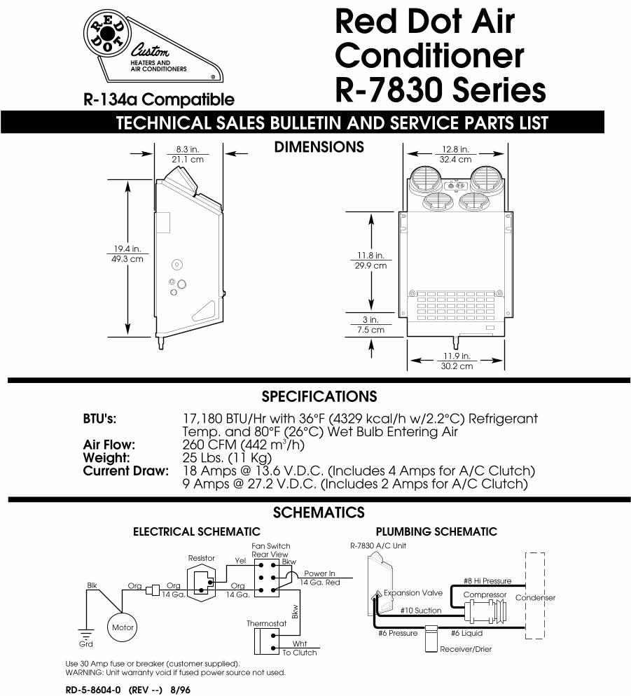
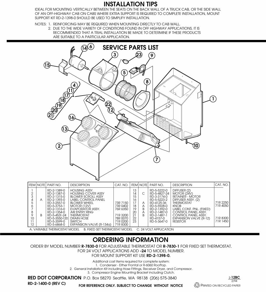
Red Dot AirConditionerR-7830 Series
TECHNICAL SALES BULLETIN AND SERVICE PARTS LIST
HEATERS ANDAIR CONDITIONERS
DIMENSIONS
SPECIFICATIONS
SCHEMATICS
BTU's:
Air Flow:Weight: Current Draw:
17,180 BTU/Hr with 36°F (4329 kcal/h w/2.2°C) Refrigerant Temp. and 80°F (26°C) Wet Bulb Entering Air260 CFM (442 m3/h)25 Lbs. (11 Kg)18 Amps @ 13.6 V.D.C. (Includes 4 Amps for A/C Clutch)9 Amps @ 27.2 V.D.C. (Includes 2 Amps for A/C Clutch)
ELECTRICAL SCHEMATIC PLUMBING SCHEMATIC
Use 30 Amp fuse or breaker (customer supplied).WARNING: Unit warranty void if fused power source not used.
Motor
Fan SwitchRear View
#8 Hi PressureOrg Org
14 Ga.
11.9 in.30.2 cm
12.8 in.32.4 cm
11.8 in.29.9 cm
19.4 in.49.3 cm
8.3 in.21.1 cm
3 in.7.5 cm
WhtTo Clutch
Power In14 Ga. Red
Resistor
Thermostat
Grd
Blk
Yel
Org14 Ga.
Bkw
#6 Liquid#6 Pressure
R-7830 A/C Unit
Compressor
Receiver/Drier
Expansion ValveCondenser
Bkw
#10 Suction
RD-5-8604-0 (REV --) 8/96
R-134a Compatible

HEATER-A/C
PAGE 27
RED DOT UNITS
R-7833 SYSTEM ORDERING GUIDE
R12/R-134a NOTESUNITS R-7833-0P 12 VDC R-7833-0-24P 24 VDC
CONDENSER R-6160-0P - Roof Mount 12 VDC –See Units Condensers section R-6160-0-24P - Roof Mount 24 VDC – See Units Condensers section 77R0650 - Radiator Mount See 77 Series Condensers section
INSTALLATION KIT 78R1025 Rooftop Condenser ATCO version 78R1027 Front mount condenser E-Z Clip version 78R1070 Front mount condenser ATCO version 78R1077 Rooftop Condenser E-Z Clip version
COMpRESSOR See 75 Series Compressor section
R134A ChARGE FITTING 75R5681 & 75R5688 Required with CCI and TECUMSEH applications.
CLUTCh TECUMSEh/CCI See 75 Series Clutch section
COMpRESSOR MOUNT KIT See Compressor Mount Applications section
OpTIONS Mounting Kit RD-5-14175-0P
R-7833 BackwallAir Conditioner UnitOff-ROad • COnstRuCtiOn • industRial
Just 12.18 inches wide, the R-7833 fits between the seats in cabs where mounting options are limited. The five louvers adjust so you can direct airflow where you need it, and the heavy-gauge welded-steel construction is ideal for severe service environments. Optional mounting brackets allow up to 4 inches of height travel.
ON/OFF-ROAD
R-7833 SpECIFICATIONS
BTU’S: Cooling – 21,000 BTU/Hr
AIR FLOw: 293 CFM (498 m³/h)
wEIGhT: 27 lbs. (12kg)
CURRENT 15.5 amps at 13.5 VDC Draw: 7.8 amps at 27 VDC
8.06"205 mm
12.18"309mm
20.262"515mm
0.966"25mm
R-7833

HE
ATER
-A/C
PAGE 30
RED DOT UNITS
R-8500 BackwallAir Conditioner with Heat OptionCONSTRUCTION • mININg • AgRICULTURe
17.5"445mm
5.6"143mm
14.5"367mm
12 VO
LT
OPTIONS:Plenum Assembly UNIVERSAL RD-3-6060-0P DUCT KITWith 2 1⁄2” hose 78R2100 adapters
Just 5.6 inches deep, the R-8500 packs high performance and reliability into a slim profile. The air plenum can be changed to divert air out the top or the front of the unit depending the application. In addition, the controls can be remote-mounted. Models include A/C only or heater and A/C combination.
OFF-ROAD
Shown with remote mount controls.

HEATER-A/C
PAGE 31
RED DOT UNITS
R-8500 SPECIFICATIONS
BTU’S Heating – 22,000 BTU/Hr @ 100°F (6.4 kW @ 37.8°C) air temperature rise Cooling – 15,200 BTU/Hr with 36°F (w 4.5 kW w/ 2.2°C) refrigerant temp. and 80°F (26.7°C) wet bulb entering air
AIR FlOw 205 CFM (348 m3/h)
wEIgHT 24 lbs. (11 kg)
mOTOR Three-speed field wound
CURRENT 13.5 amps @ 13.6 VDC (includes 4 amps for A/C clutch) DRAw 6.75 amps @ 27.2 VDC (includes 2 amps for A/C clutch)
R-8500 SySTEm ORDERINg gUIDE
R12/R-134a NOTES UNITS R-8500-2P 12 VDC – Heater - A/C R-8500-2-24P 24 VDC – Heater - A/C R-8500-3P 12 VDC – A/C Only R-8500-3-24P 24 VDC – A/C Only
CONDENSER R-9720-3P - Remote Mount 12 VDC – See Units Condensers section R-9720-3-24P - Remote Mount 24 VDC – See Units Condensers section 77R0650 - Radiator Mount See 77 Series Condensers section
gENERAl PURPOSE 78R1705 Remote Mount ATCO version INSTAllATION KIT 78R1025 Rooftop Condenser ATCO version 78R1027 Front mount condenser E-Z Clip version 78R1070 Front mount condenser ATCO version 78R0100 Heater Hose 5⁄8” diameter, 50’
COmPRESSOR See 75 Series Compressors section
R134A CHARgE FITTINg 75R5681 & 75R5688 Required with CCI and TECUMSEH applications.
ClUTCH TECUmSEH/CCI See 75 Series Clutch section
COmPRESSOR mOUNT KIT See Compressor Mount Applications section
OPTIONS Replacement Recirc Filter 78R5330 Plenum Assembly RD-3-6060-0P Universal Duct Kit 78R2100
Water Valve for Heater/AC is supplied by customer

RED DOT CORPORATION P.O. Box 88790 Seattle, WA 98138 (206) 251-6897 Fax: (206) 251-3934
FOR REFERENCE ONLY. SUBJECT TO CHANGE WITHOUT NOTICE
ITEM
123456789
10111213141516
PART NO.
RD-3-6051-0RD-3-6162-0RD-3-6055-0RD-1-0830-0RD-2-1909-0RD-5-7125-0RD-5-5965-0RD-3-6068-0RD-5-4531-24RD-3-6062-0RD-3-6062-1RD-3-6048-2RD-2-1383-1RD-5-6772-0RD-5-6772-24RD-5-3781-0
DESCRIPTION
HOUSING ASSYINTAKE FILTERCOVER ASSY (TOP)HEATER CORE ASSYEVAPORATOR ASSYEXPANSION VALVESPRING CLIP (2)GASKET (CORE)THERMOSTATMOTOR BLOWER ASSY (12V)MOTOR BLOWER ASSY (24V)BRACKET (BLOWER ASSY)ATTACH STRIP ASSYMOTOR (12V)MOTOR (24V)BLOWER HOUSING
ITEM
17181920212223242526272829303132
NOTE
A
BBBCCCCCDDD
BC
DESCRIPTION
BLOWER WHEEL (2)PLENUM ASSYLOUVER ASSY (3)LOUVER (2)ACCESSORY KITCIRCUIT BREAKER-30AMP (12V)CIRCUIT BREAKER-15AMP (24V)RELAY (12V)RELAY (24V)SWIVEL FITTING ASSY (2)CONT. PNL ASSY (A/C ONLY)CONT. PNL ASSY (A/C-HEAT)SWITCH (FAN SPEED)SWITCH (MODE A/C ONLY)SWITCH (MODE HEAT-A/C)DRAIN HOSE
A. PART OF ITEM 10/11 B. NOT SHOWN C. INCLUDED IN ACCESSORY KIT (ITEM 21) D. PART OF ITEM 27/28
PART NO.
RD-5-5656-0RD-3-6720-0RD-5-5222-0RD-5-6987-0RD-3-6727-0RD-5-5874-0RD-5-6602-0RD-5-7232-0RD-5-7233-0RD-1-0426-0RD-3-6100-0RD-3-6082-0RD-5-0071-0RD-5-3748-0RD-4123-2RD-5-6532-0
NOTE
AAAAA
1
9
12
4
1918
28
2524
27
26
6
83
7
25
1317
14 15
16
1011
ORDER BY MODEL NUMBER R-8500-0 FOR HEATER - A/C ORDER BY MODEL NUMBER R-8500-1 FOR A/C ONLY
FOR 24V ADD -24 TO MODEL NUMBER
OPTIONS: PLENUM ASSEMBLY RD-3-6060-0
ORDERING INFORMATION
RD-3-8263-0 (REV -–)
SERVICE PARTS LIST
CAT NO
76R103076R503071R8340
71R3200
73R411273R4114
CAT NO
73R7000
71R130071R131071R191271R1914
71R040071R001071R0200
20

Compact Heater-A/CR-8500 SeriesHEATERS AND
AIR CONDITIONERS
TECHNICAL SALES BULLETIN AND SERVICE PARTS LISTR-134a Compatible
RD-3-8263-0 (REV -–)
DIMENSIONS
SPECIFICATIONSBTU's:
Air Flow:Weight:Current Draw:
Heating - 22,000 BTU/Hr @ 100°F (5,544 kcal/h @ 37.8°C) Air Temp. RiseCooling - 15,200 BTU/Hr with 36°F (3,830 kcal/h w/2.2°C) Refrigerant Temp. and 80°F (26.7°C) Wet Bulb Entering Air205 CFM (348 m3/h)24 Lbs (11 Kg)13.5 Amps at 13.6 VDC (Includes 4 Amps for A/C Clutch)6.6 Amps at 27.2 VDC (Includes 2 Amps for A/C Clutch)
SCHEMATICS
12 VO
LT12 V
OLT
14.5 in(36.7 cm)
5.6 in(14.3 cm)
17.5 in(44.5 cm)
Rec/Drier
Expansion Valve
Compressor
#8 High Pressure
#6 High Pressure #6 Liquid
#10 Suction
To Frontal OrRooftopCondenser
PLUMBING SCHEMATIC
BINARY
THERMOSTAT COMPRESSOR
GROUND
GROUND
GROUND
POWERIN
BLK
BKW
BKW
PUR
BK
W
BLK
BLK
R
ED
RE
D
ORG
ORG
YELRED
ORG
ORGYEL
REDBLK
BLK85
8787A
80
86
GR
N
BLU
GRN
CIRCUITBREAKER
MOTOR
FAN SPEEDSWITCH
RELAY
ELECTRICAL SCHEMATIC

HE
ATER
-A/C
PAGE 32
RED DOT UNITS
R-8545 BackwallAir Conditioner with Heat Option CONSTRUCTION • mININg • AgRICULTURe
R-8545 SPECIFICATIONS
BTU'S Heating – 28,600 BTU/Hr @ 100°F (8.4 kW @ 37.8°C) air temperature rise Cooling – 18,000 BTU/Hr with 36°F (5.3 kW with 2.2°C) refrigerant temp. and 80°F (26.7°C) wet bulb entering air
AIR FlOw 265 CFM (450 m3/h)
wEIgHT Heater & A/C – 39 lbs. (18 kg) A/C Only – 34 lbs. (15 kg)
mOTOR Totally sealed, 12 or 24 VDC permanent magnet type with long life brushes, and heavy duty pre-lubricated sealed ball bearings
CURRENT 16.1 amps @ 13.6 VDC DRAw (includes 4 amps for A/C clutch), 8 amps @ 27.2 VDC (includes 2 amps for A/C clutch)
CONTROlS Mode selector switch (heat or A/C), three-speed fan switch, fixed setting A/C thermostat, cable controlled water valve
OFF-ROAD
Compact and powerful, the R-8545 produces the highest output of any off-road unit its size. Its performance and durability make the R-8545 the ideal choice for off-highway equipment cabs where space is a premium and reliability is essential. Engineered to filter in-cab air as well as incoming outside air when pressurization is required. Models include A/C only or heater and A/C combination.
18.2"462mm
6.8"172mm
20.4"518mm
Filter Kits for use with in-line booster pressurizer
Horizontal: 78R5100
Inline Booster Pressurizers 73R9202 (12 VDC) 73R9204 (24 VDC)
3” DEFROST HOSE SOLD SEPARATELY 78R0300
Vertical: 78R5110

HEATER-A/C
PAGE 33
RED DOT UNITS
R-8545 SySTEm ORDERINg gUIDE
R12/R-134a NOTESUNITS R-8545-14P 12 VDC – A/C Only R-8545-14-24P 24 VDC – A/C Only R-8545-12P 12 VDC – Heater-A/C R-8545-12-24P 24 VDC – Heater-A/C
CONDENSER R-9720-3P - 12V, Remote Mount See Units Condenser section R-9720-3-24P - 24V, Remote Mount See Units Condenser section 77R0650 - Radiator Mount See 77 Series Condensers section
gENERAl PURPOSE 78R1705 Remote Mount ATCO version INSTAllATION KIT 78R1025 Rooftop Condenser ATCO version 78R1027 Front mount condenser E-Z Clip version 78R1070 Front mount condenser ATCO version 78R0100 Heater Hose 5⁄8” diameter, 50’
COmPRESSOR See 75 Series Compressor section
R134A CHARgE FITTINg 75R5681 & 75R5688 Required for CCI and TECUMSEH applications.
ClUTCH TECUmSEH/CCI See 75 Series Clutch section
COmPRESSOR mOUNT KIT See Compressor Mount Applications section
OPTIONS 3” Air Outlet Adapter for Pressurization RD-3-5448-0P Remote Filters See Filters & Pressurizers section Pressurizers See Filters & Pressurizers section Universal Duct Kit 78R2100 Plenum RD-3-14486-0P
UNIVERSAL DUCT KIT 78R2100
= Limited to stock on hand

Red Dot Corporation PO Box 88790, Seattle, WA 98138 (425) 251-6897 Fax (425) 251-3934
RD-3-5370-0 REV B For Reference Only. Subject to change without notice Page 1 of 1
BackwallA/C – Heater (option)
Model R-8545SERVICE PARTS LIST
ITEM NOTE PART NO. DESCRIPTION ITEM NOTE PART NO. DESCRIPTION
1 RD-3-5264-0 HOUSING ASSY. 18 RD--2-1207-2 BLOWER ASSY.2 RD-3-5273-0P PLENUM ASSY. 19 RD-5-7311-0 BLOWER WHEEL3 RD-5-5223-1 AIR DIFFUSER ASSY.(2) 20 RD-5-7312-0 BLOWER WHEEL4 RD-5-5223-0 AIR DIFFUSER ASSY.(2) 21 RD-3-3928-2 ENTRY RINGS (2)5 RD-4427-24 THERMOSTAT 22 C RD-5-5121-0 MOTOR - 12V6 RD-3-5290-0 COVER ASSY. 23 D RD-5-5121-24 MOTOR - 24V7 A RD-5-7760-1 WATER VALVE 24 RD-3-3174-0 RETAINER - MOTOR8 RD-5-6868-0 EXPANSION VALVE 25 E RD-5-3816-18 TUBE - 5/32 I.D.9 RD-5-3647-0 RESISTOR 26 A RD-3-5277-0 CONTROL PANEL ASSY.10 A RD-1-0771-1 HEATER CORE ASSY. 27 B RD-3-5277-1 CONTROL PANEL ASSY.11 RD-2-1664-0 EVAPORATOR ASSY. 28 A, E RD-3-5413-0 LABEL - CONTROL PANEL12 RD-5-6240-0 FILTER 29 B, E RD-3-5413-1 LABEL - CONTROL PANEL13 RD-5-3550-24 DRAIN HOSE (2) 30 E RD-3-4096-0 LEVER - CONTROL14 RD-5-6239-0 SNAP FASTNER (2) 31 E RD-5-4694-1 SWITCH - SPEED, FAN15 C RD-2-1206-2 MOTOR BLWR ASSY. 32 E RD-5-3748-0 SWITCH - TOGGLE, SPST16 D RD-2-1206-3 MOTOR BLWR ASSY. 33 E RD-5-4450-0 KNOB17 RD-2-1207-1 BLOWER ASSY. 34 E RD-4180-24 CONTROL CABLE
A. HEATER A/C COMBOS ONLY B. A/C ONLYC. 12 VOLT ONLY D. 24 VOLT ONLY E. NOT SHOWN

Red Dot Corporation P.O. Box 88790, Seattle, WA 98138 (425) 251-6897 Fax (425) 251-3934
RD-5-6441-0 REV A For Reference Only. Subject to change without notice Page 1 of 5
INSTALLATION INSTRUCTIONS
Heavy Duty Heater /Air Conditioner
Model R-8545
ADDITIONAL ITEMS REQUIRED FOR COMPLETE INSTALLATION:A) Compressor 8 to 10 cubic inch displacement required (Sanden SD-508, SD-510 or
equivalent). For HFC use a compressor compatible with 134a.B) Condenser Remote Mount (R-9720 or equivalent); or Radiator Mount (77R 0650 or
equivalent). For R-134a use R-9725 or 77R 0650.C) Compressor This includes mounting hardware, belts and pulleys.
Mount KitD) Receiver Drier High capacity (12 cubic inches of desiccant) 74R 1706 or equivalent. For R-
134a applications use 74R 1816 or equivalent.E) System Protection 71R7000 binary switch, high and low pressure cut-out or equivalent dual
switches. For R-134a applications use 71R 7050.F) Refrigerant Hose Nylon Barrier or nylon lined refrigerant hose is the minimum quality
recommended for heavy duty applications. Push-on fittings can be used oneither hose although a "crimp fitting' is recommended. Reusable fittings canbe used only with the Aeroquip nylon lined hose (R-12 applications only).Galaxy hose with, beadlock crimp fittings are recommended for 134a.
A. Mounting the Unit
1. Determine the most suitable location for mounting the air conditioning unit.
2. Mark the mounting holes, drain hole locations and fresh air opening (optional) locations. See Figure 1.
NOTE: 1) If mounting template is lost the fresh air intake opening can be marked (for 78R 5150 panelfilter by scribing a side and bottom of the unit line on the mounting surface and measuring up 11/4" from the bottom (for the bottom of the fresh air opening) and 4 1/4" from the side. Thenmark a rectangular opening 2 3/4" high by 7 3/4" wide (to mark the outside of the fresh airopening).
2) If optional fresh air opening is used, fresh air door retaining screw on unit must be removed.
NOTE1. Please read instructions all the way through, making sure you have all the parts and tools2. While working on or around a vehicle, disconnect the battery to prevent accidental start up or electrical
shorts3. It has been established that R-12 refrigerant does deplete the earth’s protective ozone layer. Use care
so as not to release this material into the atmosphere4. A/C systems operate under high pressure At 77°F the refrigerant container Will be pressurized to
approximately 80 psi. Use caution When working with these materials.Goggles are recommended.
5. To function properly the A/C system must be clean and dry. Keep caps or protective covers on allhoses and fittings until final assembly
6. IMPORTANT: Attach appropriate SAE warning label to vehicle.

Red Dot Corporation P.O. Box 88790, Seattle, WA 98138 (425) 251-6897 Fax (425) 251-3934
RD-5-6441-0 REV A For Reference Only. Subject to change without notice Page 2 of 5
3. Drill the mounting holes and remove burrs and sharp edges.
4. Mount unit to cab using mounting bolts, nuts and washers. See Figure 1.
B. Compressor Mounting
1. Install compressor mounting hardware to engine block.NOTE: Red Dot does not recommend any compressor mount designs that are not directly attached to the
engine.If fabrication of compressor mounting bracket is required, be sure to design so the belt wrap is aminimum of 1/3 around the clutch pulley and can be tensioned easily. If designing for a SandenCompressor, Red Dot does provide an adjustable adapter bracket 75R 6010 which often savestime in design and fabrication. See Figure 2.
2. Install compressor making sure to properly align and tension drive belt.

Red Dot Corporation P.O. Box 88790, Seattle, WA 98138 (425) 251-6897 Fax (425) 251-3934
RD-5-6441-0 REV A For Reference Only. Subject to change without notice Page 3 of 5
C. Condenser Mounting (Remote or Radiator Style) Remote Mount1. Locate in an area easily accessible and free of dust and other debris.2. Mount in a position so that the large (#8) hose fitting is above the small (#6) hose fitting. Radiator Mount1. A radiator mounted condenser will be effective only if positioned to receive maximum air flow.2. Install condenser allowing a minimum of 1.5 inch air space between the condenser and the radiator to
prevent heat transfer from the radiator, Also, all radiators should have baffles on top and sides to preventhot air recirculating back around the radiator.
D. Refrigerant Hose Installation1. Determine desired hose routing and measure hose lengths, per plumbing schematic,
See Figure 3.NOTE: if suction line #10 hose length is longer than 10 feet, Red Dot recommends using #12 refrigeranthose and "step-up" refrigerant fittings. This will improve system function.
2. Cut refrigerant hose to length using a knife. Do Not Saw Off. See Figure 4.
3. Install fittings on hose. See Figure 4, (Be sure to clean out refrigerant hose after cutting).
4. Additional refrigerant oil is required for long hose applications.
5. Lubricate "O" rings with mineral oil and attach to fittings. Route and connect #6, #8 and #10hoses to unit, compressor, condenser, and receiver drier per plumbing schematic.See Figure 3.
6. Use clamps to secure hoses and prevent hose movement. Hoses must not come in contact with hotengine components (exhaust manifold, etc.) and they should not be subject to mechanical abrasions

Red Dot Corporation P.O. Box 88790, Seattle, WA 98138 (425) 251-6897 Fax (425) 251-3934
RD-5-6441-0 REV A For Reference Only. Subject to change without notice Page 4 of 5
E. Drain Hose InstallationNOTE: See Figure 5 for additional information on drain hose installation.
1. Attach drain hose assembly to the unit.
2. Route drain hoses out the cab at desired location. Be certain the drain hose runs downhill
from the unit at a minimum slope angle of 20° .
3. Secure drain hoses with tie wraps, inspect to make sure hoses are not kinked or pinched off.

Red Dot Corporation P.O. Box 88790, Seattle, WA 98138 (425) 251-6897 Fax (425) 251-3934
RD-5-6441-0 REV A For Reference Only. Subject to change without notice Page 5 of 5
F. Unit WiringNOTE: See Figure 6 for wiring diagram.
1. Disconnect battery.2. Black W/White - Route to A/C clutch through low pressure protection switch if included.3. Red Wire - Connect to an ignition switch supply through a 30 amp circuit breaker for
12 volt system; a 15 amp circuit breaker for 24 volt system.4. Black Wire - Unit grounding wire.5. Brown Wire - Route to condenser fan relay (remote mount condenser).
G. Final Assembly and Check
WARNINGThe owner/operator of the R-8545 unit accepts the responsibility for the proper and safe installation andmaintenance of the unit. Special attention must be given to the mounting as well as the hose assembly andconnections to be sure that they are securely fastened and in good condition to preclude the possibility ofpersonal injury.
1. Connect the battery.2. Evacuate the system, then charge with refrigerant.3. Turn the ignition switch to the "On" position and place the fan speed switch on the highest position.4. Place the Heat-A/C switch to the "A/C" position and the temperature control lever on the coldest position.
a. The clutch should click on and be engaged.b. The evaporator blower should be turning at high speed.
5. Turn the fan switch to the "Off" position and compressor clutch should disengage.6. Move the Heat-A/C switch to the "Heat" position and compressor should disengage.7. Start engine and run at 1200-1500 rpm. Place the Heat-A/C switch to the "A/C" position and the fan
speed on high. Check sight glass on receiver drier for bubbles. Add 6 to 8 ounces more R-12 after thesight glass just clears.
NOTE: Be aware that the sight glass may appear "milky" when charging with R-134a. Be careful not toovercharge the system.
8. Make sure clutch cycles off and on as system is operating