Embed Size (px)
Citation preview

InstructIon manualModel no.: KDR-4E-3
CLARITY
INSTANTHEATING FAUCET

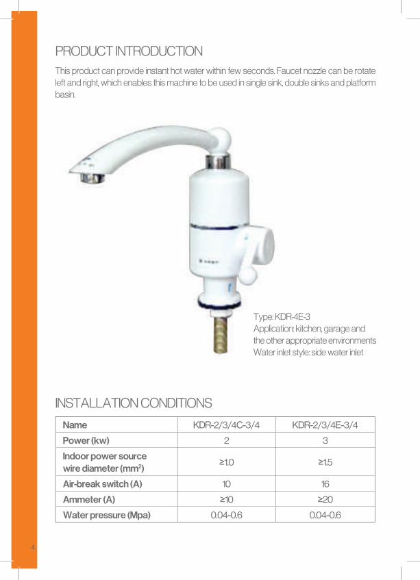
3
product IntroductIon 3
InstallatIon condItIons 3
InstallatIon methods of products 5 InstallatIon method of downsIde-Inlet machInes 6
Key poInts In InstallatIon and adjustment 7
operatIng method 8
maIntenance method 8
attentIons 9
electrIcal dIagram 10
fault analysIs and clearIng methods 10
pacKIng lIst 11
maIn accessorIes 11
Thank you for buying our Delimano Instant Heating Faucet.Please read the manual carefully before using and keep it for the future reference.
4
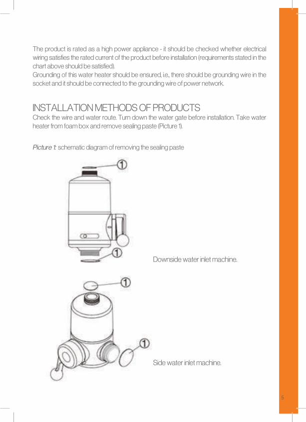
this product can provide instant hot water within few seconds. faucet nozzle can be rotate left and right, which enables this machine to be used in single sink, double sinks and platform basin.
product IntroductIon
type: Kdr-4e-3application: kitchen, garage and the other appropriate environmentswater inlet style: side water inlet
InstallatIon condItIons
Name KDR-2/3/4C-3/4 KDR-2/3/4E-3/4
Power (kw) 2 3
Indoor power source wire diameter (mm2)
≥1.0 ≥1.5
Air-break switch (A) 10 16
Ammeter (A) ≥10 ≥20
Water pressure (Mpa) 0.04-0.6 0.04-0.6
5
the product is rated as a high power appliance - it should be checked whether electrical wiring satisfies the rated current of the product before installation (requirements stated in the chart above should be satisfied).grounding of this water heater should be ensured, i.e., there should be grounding wire in the socket and it should be connected to the grounding wire of power network.
InstallatIon methods of productscheck the wire and water route. turn down the water gate before installation. take water heater from foam box and remove sealing paste (picture 1).
downside water inlet machine.
Picture 1: schematic diagram of removing the sealing paste
side water inlet machine.
6
1 - water outlet pipe2 - main engine3 - rubber ring of connecting piece4 - downside-inlet connecting piece5 - base rubber ring6 - sink7 - fixing nut8 - water supply pipe
InstallatIon method of downsIde-Inlet machInes
1. abut water outlet pipe with main engine and screw tight. (note: do not damage rubber ring during installation).2. embed sealing ring into base of main engine with crown upward. then screw downside-inlet connecting piece into base of main engine and screw tight.
3. Insert the installed downside-inlet connecting piece into rubber ring of the base, and install them into the sink. screw a fixing nut from below the sink to fasten main engine.
4. connect water supply pipe with water inlet of downside-inlet connecting piece.
5. open water gate, press down handle of main engine, rotate water outlet to left and right check and eliminate leakage before usage.
6. Insert plug into power source socket nearby.
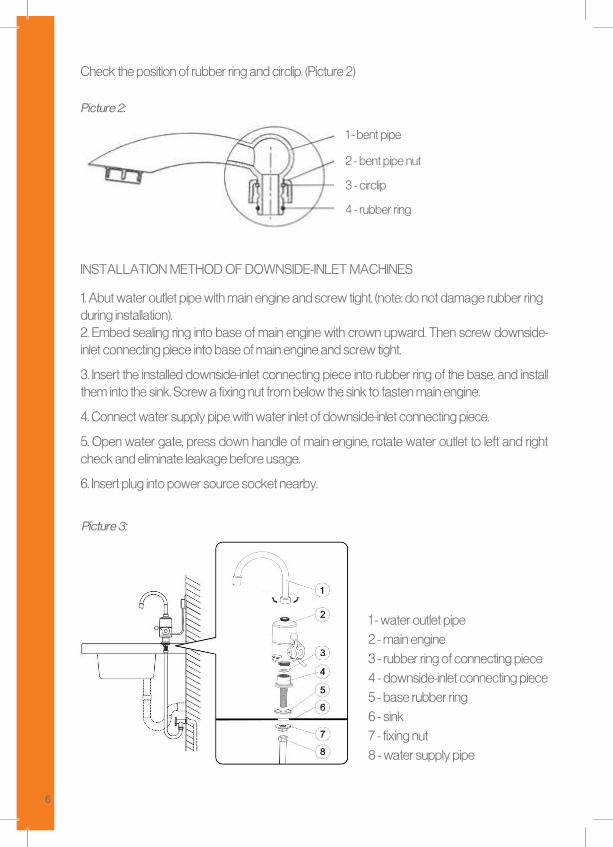
check the position of rubber ring and circlip. (picture 2)
Picture 2:
1 - bent pipe
2 - bent pipe nut
3 - circlip
4 - rubber ring
Picture 3:
7
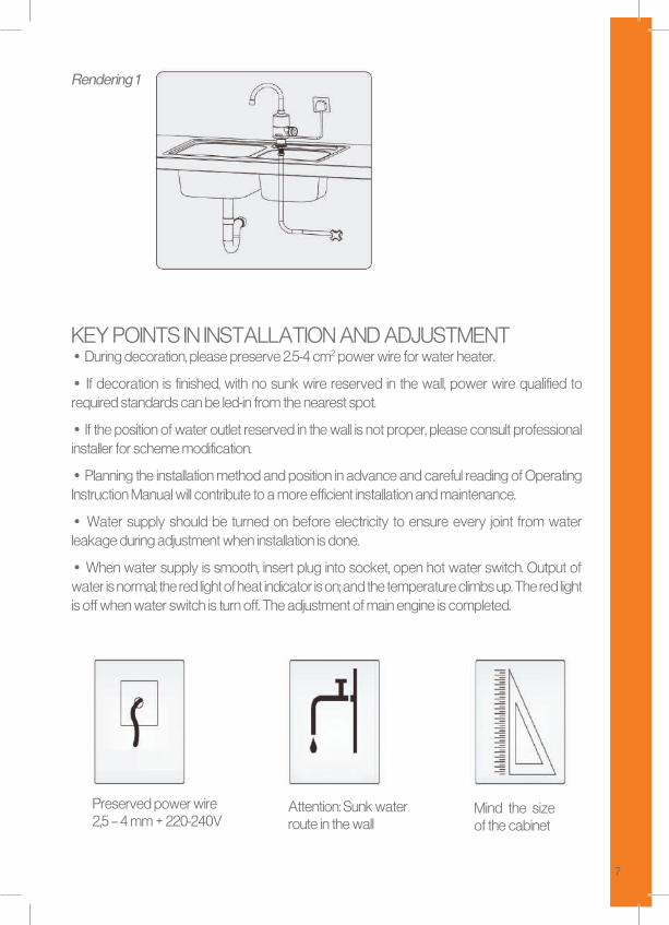
Rendering 1
Key poInts In InstallatIon and adjustment• during decoration, please preserve 2.5-4 cm2 power wire for water heater.
• If decoration is finished, with no sunk wire reserved in the wall, power wire qualified to required standards can be led-in from the nearest spot.
• If the position of water outlet reserved in the wall is not proper, please consult professional installer for scheme modification.
• planning the installation method and position in advance and careful reading of operating Instruction manual will contribute to a more efficient installation and maintenance.
• water supply should be turned on before electricity to ensure every joint from water leakage during adjustment when installation is done.
• when water supply is smooth, insert plug into socket, open hot water switch. output of water is normal; the red light of heat indicator is on; and the temperature climbs up. the red light is off when water switch is turn off. the adjustment of main engine is completed.
preserved power wire 2,5 – 4 mm + 220-240V
attention: sunk water route in the wall
mind the size of the cabinet
8
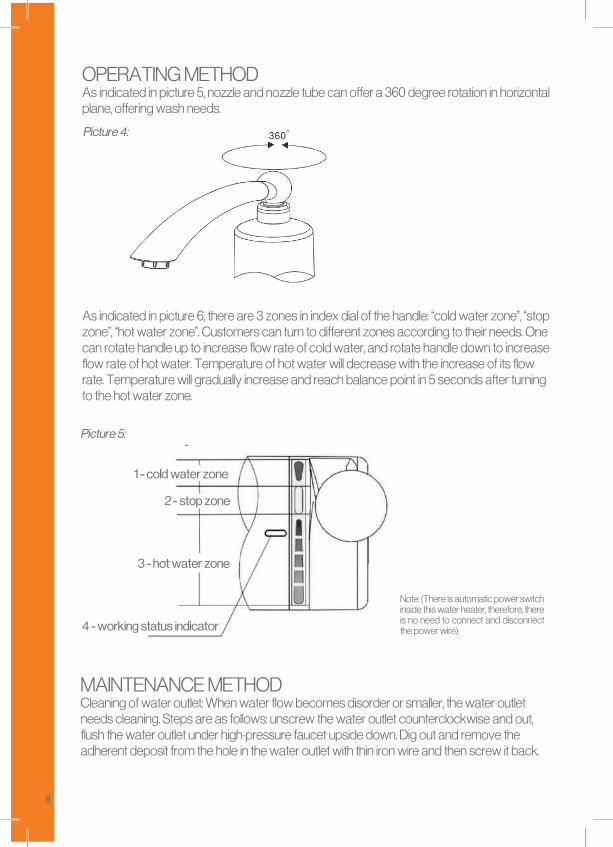
operatIng methodas indicated in picture 5, nozzle and nozzle tube can offer a 360 degree rotation in horizontal plane, offering wash needs.
as indicated in picture 6, there are 3 zones in index dial of the handle: “cold water zone”, “stop zone”, “hot water zone”. customers can turn to different zones according to their needs. one can rotate handle up to increase flow rate of cold water, and rotate handle down to increase flow rate of hot water. temperature of hot water will decrease with the increase of its flow rate. temperature will gradually increase and reach balance point in 5 seconds after turning to the hot water zone.
Picture 4:
4 - working status indicator
1 - cold water zone
2 - stop zone
3 - hot water zone
Picture 5:
note: (there is automatic power switch inside this water heater, therefore, there is no need to connect and disconnect the power wire).
maIntenance methodcleaning of water outlet: when water flow becomes disorder or smaller, the water outlet needs cleaning. steps are as follows: unscrew the water outlet counterclockwise and out, flush the water outlet under high-pressure faucet upside down. dig out and remove the adherent deposit from the hole in the water outlet with thin iron wire and then screw it back.
9
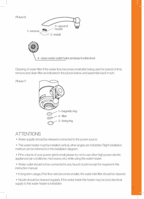
Picture 6:
1 - remove
3 - spool of nozzle
2 - install
cleaning of water filter: If the water flow becomes small after being used for period of time, remove and clean filter as indicated in the picture below, and assemble back in turn.
Picture 7:
3 - fixing ring
1 - magnetic ring
2 - filter
attentIons• water supplly should be released connected to the power source.
• this water heater must be installed vertical, other angles are forbidden. right installation method can be referred to in the installation diagram.
• If the volume of your power grid is small, please try not to use other high-power electric appliances (air conditioner, microwave, etc.) while using this water heater.
• water outlet should not be connected to any faucet or joint except for required in this instruction manual.
• In long-term usage, if the flow rate becomes smaller, the water inlet filter should be cleaned.
• nozzle should be cleaned regularly. If the water inside this heater may be iced, electrical supply to this water heater is forbidden.
4 - clean water outlet holes and jeep it unblocked
10
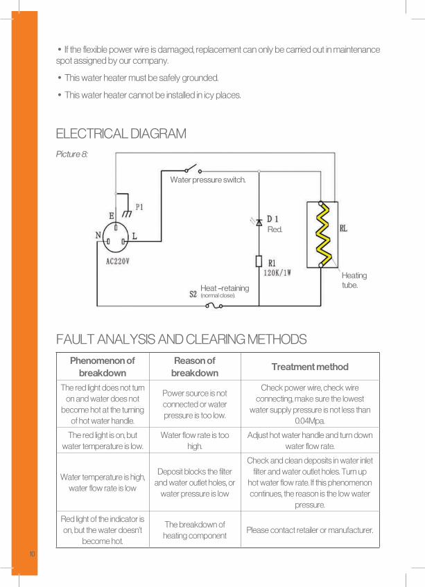
Water pressure switch.
Heat –retaining (normal close).
Heating tube.
Red.
Picture 8:
• If the flexible power wire is damaged, replacement can only be carried out in maintenance spot assigned by our company.
• this water heater must be safely grounded.
• this water heater cannot be installed in icy places.
electrIcal dIagram
fault analysIs and clearIng methodsPhenomenon of
breakdownReason of
breakdownTreatment method
the red light does not turn on and water does not
become hot at the turning of hot water handle.
power source is not connected or water pressure is too low.
check power wire, check wire connecting, make sure the lowest
water supply pressure is not less than 0.04mpa.
the red light is on, but water temperature is low.
water flow rate is too high.
adjust hot water handle and turn down water flow rate.
water temperature is high, water flow rate is low
deposit blocks the filter and water outlet holes, or
water pressure is low
check and clean deposits in water inlet filter and water outlet holes. turn up
hot water flow rate. If this phenomenon continues, the reason is the low water
pressure.
red light of the indicator is on, but the water doesn’t
become hot.
the breakdown of heating component
please contact retailer or manufacturer.
11
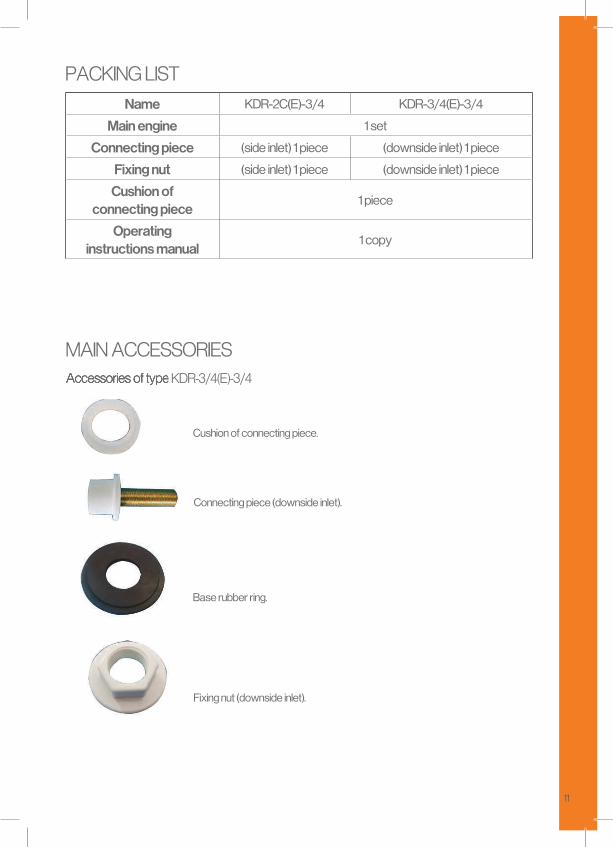
pacKIng lIstName KDR-2C(E)-3/4 KDR-3/4(E)-3/4
Main engine 1 set
Connecting piece (side inlet) 1 piece (downside inlet) 1 piece
Fixing nut (side inlet) 1 piece (downside inlet) 1 piece
Cushion ofconnecting piece
1 piece
Operatinginstructions manual
1 copy
maIn accessorIesaccessories of type Kdr-3/4(e)-3/4accessories of type Kdr-3/4(e)-3/4
Cushion of connecting piece.
Connecting piece (downside inlet).
Base rubber ring.
Fixing nut (downside inlet).

VISITWWW.DELIMANO.AL