Embed Size (px)
Citation preview
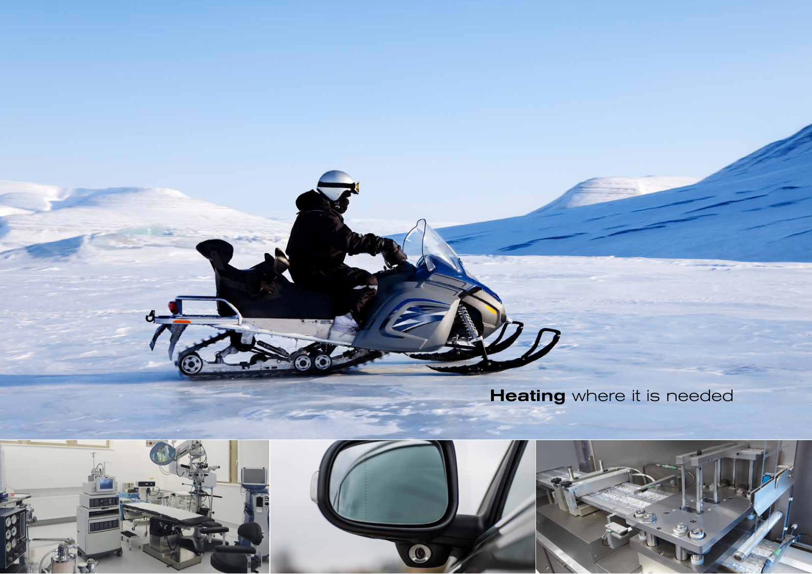
Heating where it is needed
4 5
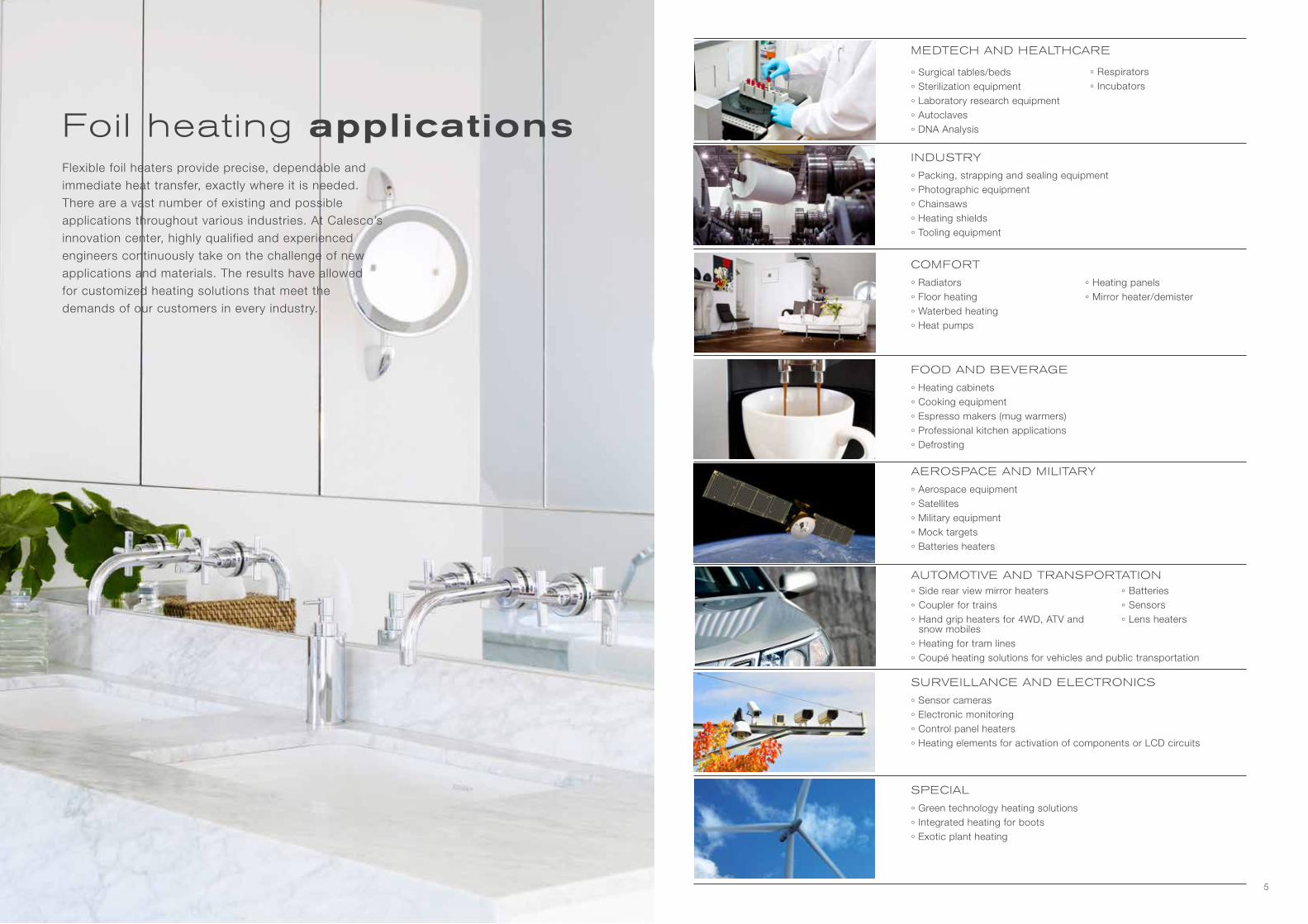
Flexible foil heaters provide precise, dependable and immediate heat transfer, exactly where it is needed. There are a vast number of existing and possible applications throughout various industries. At Calesco’s innovation center, highly qualified and experienced engineers continuously take on the challenge of new applications and materials. The results have allowed for customized heating solutions that meet the demands of our customers in every industry.
Foil heating applications
MEDTECH AND HEALTHCARE
AEROSPACE AND MILITARY
COMFORT
INDUSTRY
AUTOMOTIVE AND TRANSPORTATION
SPECIAL
° Surgical tables/beds
° Sterilization equipment
° Laboratory research equipment
° Autoclaves
° DNA Analysis
° Respirators
° Incubators
° Radiators
° Floor heating
° Waterbed heating
° Heat pumps
° Heating panels
° Mirror heater/demister
° Side rear view mirror heaters
° Coupler for trains
° Hand grip heaters for 4WD, ATV and snow mobiles
° Heating for tram lines
° Coupé heating solutions for vehicles and public transportation
° Green technology heating solutions
° Integrated heating for boots
° Exotic plant heating
° Aerospace equipment
° Satellites
° Military equipment
° Mock targets
° Batteries heaters
FOOD AND BEVERAGE
° Heating cabinets
° Cooking equipment
° Espresso makers (mug warmers)
° Professional kitchen applications
° Defrosting
° Packing, strapping and sealing equipment
° Photographic equipment
° Chainsaws
° Heating shields
° Tooling equipment
SURVEILLANCE AND ELECTRONICS
° Sensor cameras
° Electronic monitoring
° Control panel heaters
° Heating elements for activation of components or LCD circuits
° Batteries
° Sensors
° Lens heaters

6 7
At Calesco, we develop new products and solutions in close cooperation with our customers,
transforming a customer request into a working solution. The process is successfully achieved
from our broad experience, advanced design tools and efficient production capabilities.
The idea takes shape at the drawing board
Etching the circuitAutomated component placement and soldering station
Component assembly
Performance testingFinal testing
Automated silk screen production
Printing a circuit6 meter vacuum tables
Inspection and verification
Measuring and technical documentation
Laser cutting
From idea to solution
Long term testing
Climate chamber testing
8 9
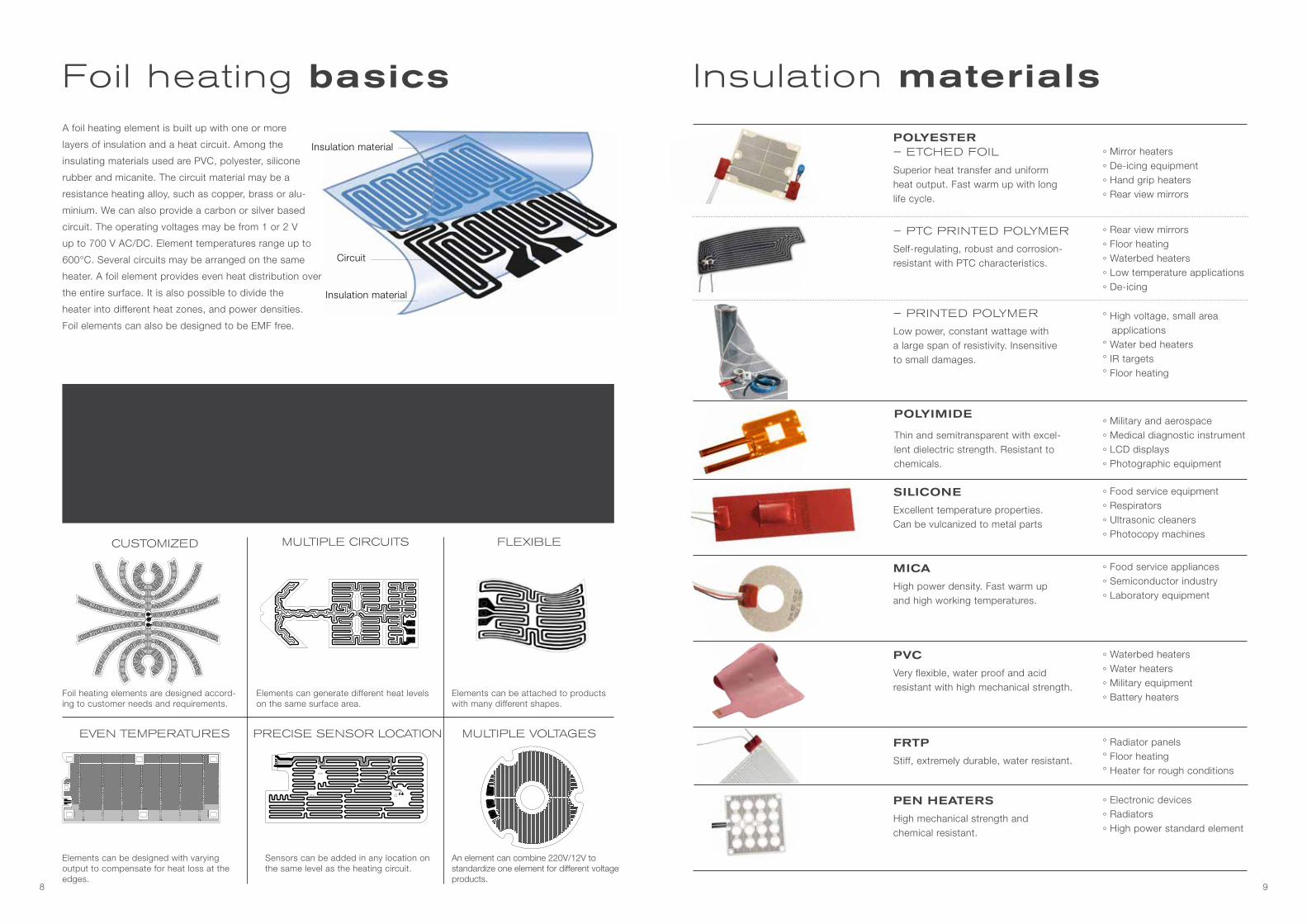
POLYIMIDE
Thin and semitransparent with excel-lent dielectric strength. Resistant to chemicals.
° Military and aerospace
° Medical diagnostic instrument
° LCD displays
° Photographic equipment
– PTC PRINTED POLYMER
Self-regulating, robust and corrosion- resistant with PTC characteristics.
° Rear view mirrors
° Floor heating
° Waterbed heaters
° Low temperature applications
° De-icing
PEN HEATERS
High mechanical strength and chemical resistant.
° Electronic devices
° Radiators
° High power standard element
MICA
High power density. Fast warm up and high working temperatures.
° Food service appliances
° Semiconductor industry
° Laboratory equipment
POLYESTER– ETCHED FOIL
Superior heat transfer and uniform heat output. Fast warm up with long life cycle.
° Mirror heaters
° De-icing equipment
° Hand grip heaters
° Rear view mirrors
SILICONE
Excellent temperature properties. Can be vulcanized to metal parts
° Food service equipment
° Respirators
° Ultrasonic cleaners
° Photocopy machines
PVC
Very flexible, water proof and acid resistant with high mechanical strength.
° Waterbed heaters
° Water heaters
° Military equipment
° Battery heaters
FRTP
Stiff, extremely durable, water resistant.
° Radiator panels° Floor heating° Heater for rough conditions
– PRINTED POLYMER
Low power, constant wattage with a large span of resistivity. Insensitive to small damages.
° High voltage, small area applications° Water bed heaters° IR targets° Floor heating
Insulation materialsFoil heating basicsA foil heating element is built up with one or more
layers of insulation and a heat circuit. Among the
insulating materials used are PVC, polyester, silicone
rubber and micanite. The circuit material may be a
resistance heating alloy, such as copper, brass or alu-
minium. We can also provide a carbon or silver based
circuit. The operating voltages may be from 1 or 2 V
up to 700 V AC/DC. Element temperatures range up to
600°C. Several circuits may be arranged on the same
heater. A foil element provides even heat distribution over
the entire surface. It is also possible to divide the
heater into different heat zones, and power densities.
Foil elements can also be designed to be EMF free.
FLEXIBLEMULTIPLE CIRCUITSCUSTOMIZED
MULTIPLE VOLTAGESPRECISE SENSOR LOCATIONEVEN TEMPERATURES
Foil heating advantages
• Customized shapes
• Multiple temperature zones
• Flexibility
• Thin
• Light weight
• Simple assembly
• Quick heating
• Efficient heat transmission
• Low energy consumption
• High quality
Insulation material
Insulation material
Circuit
Foil heating elements are designed accord-ing to customer needs and requirements.
Elements can be designed with varying output to compensate for heat loss at the edges.
Elements can generate different heat levels on the same surface area.
Sensors can be added in any location on the same level as the heating circuit.
Elements can be attached to products with many different shapes.
An element can combine 220V/12V to standardize one element for different voltage products.
10 11
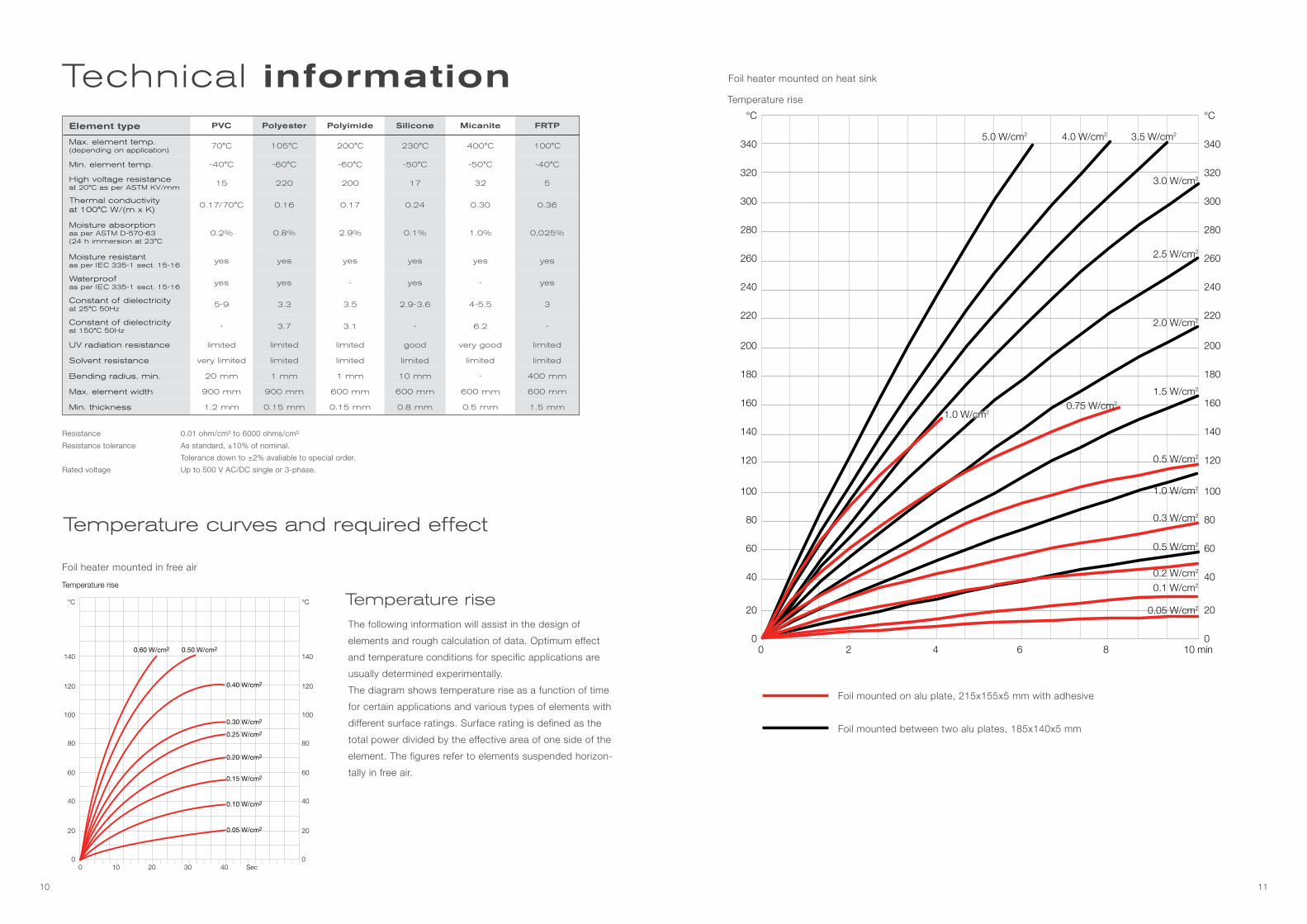
Technical information
0 10 20 30 40 Sec
°C
140
120
100
80
60
40
20
0
°C
140
120
100
80
60
40
20
0
Temperature rise
0.60 W/cm2 0.50 W/cm2
0.40 W/cm2
0.30 W/cm2
0.25 W/cm2
0.20 W/cm2
0.15 W/cm2
0.10 W/cm2
0.05 W/cm2
Temperature rise
Temperature curves and required effect
The following information will assist in the design of
elements and rough calculation of data. Optimum effect
and temperature conditions for specific applications are
usually determined experimentally.
The diagram shows temperature rise as a function of time
for certain applications and various types of elements with
different surface ratings. Surface rating is defined as the
total power divided by the effective area of one side of the
element. The figures refer to elements suspended horizon-
tally in free air.
Foil mounted on alu plate, 215x155x5 mm with adhesive
Foil mounted between two alu plates, 185x140x5 mm
Element type PVC Polyester Polyimide Silicone Micanite FRTP
Max. element temp.(depending on application)
70°C 105°C 200°C 230°C 400°C 100°C
Min. element temp. -40°C -60°C -60°C -50°C -50°C -40°C
High voltage resistanceat 20°C as per ASTM KV/mm
15 220 200 17 32 5
Thermal conductivityat 100°C W/(m x K)
0.17/70°C 0.16 0.17 0.24 0.30 0.36
Moisture absorption as per ASTM D-570-63 (24 h immersion at 23°C
0.2% 0.8% 2.9% 0.1% 1.0% 0,025%
Moisture resistant as per IEC 335-1 sect. 15-16
yes yes yes yes yes yes
Waterproof as per IEC 335-1 sect. 15-16
yes yes - yes - yes
Constant of dielectricity at 25°C 50Hz
5-9 3.3 3.5 2.9-3.6 4-5.5 3
Constant of dielectricity at 150°C 50Hz
- 3.7 3.1 - 6.2 -
UV radiation resistance limited limited limited good very good limited
Solvent resistance very limited limited limited limited limited limited
Bending radius, min. 20 mm 1 mm 1 mm 10 mm - 400 mm
Max. element width 900 mm 900 mm 600 mm 600 mm 600 mm 600 mm
Min. thickness 1.2 mm 0.15 mm 0.15 mm 0.8 mm 0.5 mm 1.5 mm
Resistance 0.01 ohm/cm² to 6000 ohms/cm²
Resistance tolerance As standard, ±10% of nominal.
Tolerance down to ±2% avaliable to special order.
Rated voltage Up to 500 V AC/DC single or 3-phase.
Foil heater mounted in free air
°C
340
320
300
280
260
240
220
200
180
160
140
120
100
80
60
40
20
0
°C
340
320
300
280
260
240
220
200
180
160
140
120
100
80
60
40
20
00 2 4 6 8 10 min
Temperature rise
5.0 W/cm2 4.0 W/cm2 3.5 W/cm2
3.0 W/cm2
2.5 W/cm2
2.0 W/cm2
1.5 W/cm2
1.0 W/cm20.75 W/cm2
0.5 W/cm2
0.3 W/cm2
0.2 W/cm2
0.1 W/cm2
0.05 W/cm2
1.0 W/cm2
0.5 W/cm2
Foil heater mounted on heat sink
12 13
Temperature controlIn conjunction with Calesco foil heating elements it is
usually necessary to arrange some form of control to
ensure that the desired temperature is maintained. A foil
element has very small mass and is quickly heated.
Accurate temperature control is therefore needed. This
can be achieved with electromechanical thermostats of
bimetallic type when temperatures and surface ratings
are low, while electronic thermostats are preferred when
temperatures and surface loads are high.
We can fit thermostats, temperature fuses and sensors
of thermo element type, thermistors and resistance
sensors directly to elements in accordance with
customer specifications. This helps to ensure
reliable control. The placing of components
can vary. It is often preferable to minimize ele-
ment temperature and accept a deviation from
the ideal working temperature. Final decision on thermo-
stat temperature settings and location can often be made
only after practical tests.
Calculation of power
(cm2)
5000
4000
3000
2000
1000
0
Amax (single-sided)
0 1 2 3 II(mA)
Leakage currents for foil heaters at 220√ 1.15 V for various insulation materials and thicknesses
0.380 mm 0.190 mm
0.300 mm
0.125 mm
0.200 mm
0.075 mm
0.050 mm
0.025 mm
The following formula can be used to determine the required rating
P to heat a given material approximately.
Specification of heat and density of common materials:
Material Spec. heat Ws/(g °C)
Densityg/cm3
Aluminium 0.90 2.7
Copper 0.39 8.9
Stainless Steel 0.50 8.0
Iron 0.46 7.8
Water 4.18 1.0
Electrical insulation and calculating leakage currentWhen a foil element is fitted on a metal surface,
leakage current must be taken into account.
In industrial and low-voltage (<48V ~) applications
there are no limitations regarding leakage current,
while strict limitations apply to household applianc-
es. The basic standard for heating appliances is laid
down in the test rules IEC 6605, on which various
national standards (SEMKO, NEMKO, DEMKO, VDE
etc.) are based.
The maximum level of leakage current for Class I
(earthed) appliances is 0.75 mA/kW while for Class
II (double insulated) appliances it is 0.25 mA/kW.
Medical appliances are subject to special leakage
current restrictions as per IEC 601.
Weight of material (g) x spec. heat ( Ws/(g °C)) x temp. rise (°C)
Time sec.P = W
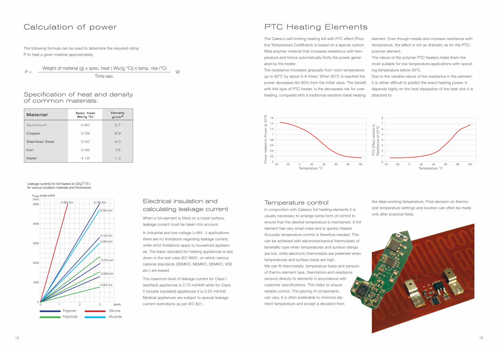
PTC Heating ElementsThe Calesco self-limiting heating foil with PTC effect (Posi-
tive Temperature Coefficient) is based on a special carbon
filled polymer material that increases resistance with tem-
perature and hence automatically limits the power gener-
ated by the heater.
The resistance increases gradually from room temperature
up to 80°C by about 5–6 times. When 80°C is reached the
power decreases 80–85% from the initial value. The benefit
with this type of PTC heater, is the decreased risk for over-
heating, compared with a traditional resistive metal heating
element. Even though metals also increase resistance with
temperature, the effect is not as dramatic as for the PTC/
polymer element.
The nature of the polymer PTC heaters make them the
most suitable for low temperature applications with operat-
ing temperature below 30°C.
Due to the variable nature of the resistance in the element,
it is rather difficult to predict the exact heating power. It
depends highly on the heat dissipation of the heat sink it is
attached to.
Temperature °C
PTC
Effe
ct r
elat
ed t
o R
esis
tanc
e at
20°
C
Temperature °C
Pow
er r
elat
ed t
o P
ower
at
20°C 1,6
1,4
1,2
1
0,8
0,6
0,4
0,2
0-40 -20 0 20 40 60 80 100
8
7
6
5
4
3
2
1
0-40 -20 0 20 40 60 80 100
Polyester Silicone
Polyimide Micanite
14
Backer BHV AB
div. Calesco
Västra Åvägen 11
SE-734 51 Kolbäck
Sweden
tel: +46 220 453 00
www.calescofoil.se
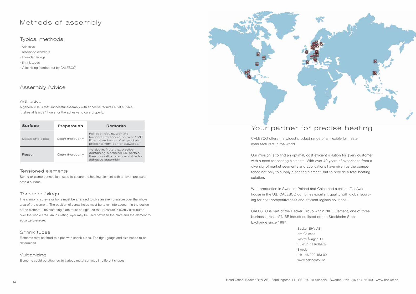
CALESCO offers the widest product range of all flexible foil heater
manufacturers in the world.
Our mission is to find an optimal, cost efficient solution for every customer
with a need for heating elements. With over 40 years of experience from a
diversity of market segments and applications have given us the compe-
tence not only to supply a heating element, but to provide a total heating
solution.
With production in Sweden, Poland and China and a sales office/ware-
house in the US, CALESCO combines excellent quality with global sourc-
ing for cost competitiveness and efficient logistic solutions.
CALESCO is part of the Backer Group within NIBE Element, one of three
business areas of NIBE Industrier, listed on the Stockholm Stock
Exchange since 1997.
Head Office: Backer BHV AB · Fabriksgatan 11 · SE-280 10 Sösdala · Sweden · tel: +46 451 66100 · www.backer.se
Methods of assembly
Typical methods:· Adhesive
· Tensioned elements
· Threaded fixings
· Shrink tubes
· Vulcanizing (carried out by CALESCO)
Assembly Advice
AdhesiveA general rule is that successful assembly with adhesive requires a flat surface.
It takes at least 24 hours for the adhesive to cure properly.
Surface Preparation Remarks
Metals and glass Clean thoroughly
For best results, working temperature should be over 15°C.Ensure exclusion of air pockets. pressing from center outwards.
Plastic Clean thoroughly
As above. Note that plastics containing plasticizer i.e. certain thermoplastics, are unsuitable for adhesive assembly.
Tensioned elementsSpring or clamp connections used to secure the heating element with an even pressure
onto a surface.
Threaded fixingsThe clamping screws or bolts must be arranged to give an even pressure over the whole
area of the element. The position of screw holes must be taken into account in the design
of the element. The clamping plate must be rigid, so that pressure is evenly distributed
over the whole area. An insulating layer may be used between the plate and the element to
equalize pressure.
Shrink tubesElements may be fitted to pipes with shrink tubes. The right gauge and size needs to be
determined.
VulcanizingElements could be attached to various metal surfaces in different shapes.
Your partner for precise heating
Backer BHV AB, div Calesco, Västra Åvägen 11, SE-730 40 Kolbäck, SWEDEN, Tel: +46 220 453 00, www.calescofoil.se