Embed Size (px)
Citation preview

Amphenol /Pyle Industrial ConnectorsStar-Line , Star-Line EX , Star-Lok12-054-2
Heavy Duty,Environmentally Sealed,Power and Control Connectors
Amphenol
® ®
® ® ®

ContentsStar-Line® Series Overview......................................................................................... 1
Star-Line EX® Series Overview ................................................................................... 2
Star-LokTM Series Overview ........................................................................................ 3
Environmental Highlights, Double Lead Acme Thread Features,Wire Limitation Guide.................................................................................................. 4
Contact Insert Features-Mod I, Mod II, Mod III ....................................................5 - 6
Connector Component Ordering Details .............................................................7 - 11
Plug Hardware Assemblies ............................................................................... 12 - 15
Receptacle Hardware Assemblies .................................................................... 16 - 23
EX Ordering Details, EEx d Cable Types ......................................................... 24 - 25
EX Hardware ..................................................................................................... 26 - 28
Insert Configuration Listing, Electrical Ratings................................................. 29 - 30
Spare Replacement Contacts for MOD II and MOD III Inserts ............................... 31
Termination Data ...................................................................................................... 32
Thermocouple Contacts ........................................................................................... 33
Insert Configuration Index ................................................................................ 34 - 36
Insert Configurations ......................................................................................... 37 - 63
Connector Components, Spare Parts, Cable Adapters and Accessories ....... 64 - 71
Protection Covers and Caps Accessories ........................................................ 72 - 73
Conduit System Accessories ............................................................................ 74 - 75
Crimping, Insertion and Removal Tools ........................................................... 76 - 77
Single Pole Power Connectors ......................................................................... 78 - 79
Connector Assembly and Termination Instructions ................................................. 80
Connectors with RADSOK® High Amperage Contacts andOther Amphenol®/Pyle® Connectors ................................................................. 81 - 83
Sales Offices and Distributors Listing ....................................................................... 84
Catalog information for reference only. For moreassistance, contact your local Amphenol field salesoffice or:Amphenol Industrial Operations40-60 Delaware Avenue,Sidney, NY 13838-1395Phone: 607-563-5011 or 800-678-0141Fax: 607-563-5157
This catalog and most all Amphenol catalogs areavailable for viewing, printing and downloading onwebsites:www.amphenol-industrial.comwww.amphenol-aerospace.com

AmphenolINDUSTRIAL
1
RoHSAmphenol
EU/ 2002 / 95 / EC
STAR-LINE® SeriesStar-Line Series “ZP/ZR” connectors are heavy duty environmentally sealed plugs and receptacles and have beensuccessfully used in all types of Industrial and Aerospace applications. These compact environmental connectors haveprovided outstanding performance in complex ground support cable networks, automatic and process control systemsand instrumentation systems.
This family of connectors has made a major contribution to the successful interconnection of peak power generatingsystems as well as offshore petroleum production for power distribution and data acquisition.
Ample margins of safety and reliability have been designed into the Star-Line connectors to maintain capability levelswhich make them ideally suited for the broad spectrum of demands placed on them by industry.
The specific materials and design features incorporated in Star-Line connectors were originally selected to satisfy thestringent requirements of the Aerospace industry for heavy-duty connectors. These connectors combine electrical andmechanical capabilities that equal or exceed the performance parameters established by the Military Specification MIL-5015.
• UL & CSA listed to new 1682 requirements
• ENVIRONMENTAL RESISTANCE – Design and materials withstand the most challenging operating conditions.Series has an IP 67 rating.
• SOLDER, CRIMP AND PRESSURE TERMINALS AVAILABLE
• EASILY ACCESSIBLE WIRE TERMINALS – Conductors are readily terminated to contacts. Cable housings areslipped over conductors or leads after terminating. Cumbersome handling and seating of inserts with conductorsattached is eliminated.
• LARGE WIRING SPACE – Ample wiring space is provided in cable housings and conduit fitting bodies. Hub of bodymounts in any of four positions (except FS & FD box assemblies).
• REVERSIBLE INSERTS – A full range of contact inserts and application adapters are available. All are interchange-able and reversible to suit special needs.
* Star-line Series Connectors are certified to UL 1682 specifications.
• DOUBLE-LEAD THREAD COUPLING – ModifiedAcme Thread does not clog under adverse condi-tions of ice, snow, sand or mud and provides thequick coupling feature.
• HARD ANODIC COATING – All machine, aluminumparts finished with a hard, scratch-resistant coatingper MIL-A-8625, Type III. Dielectric strength 1800volts. Heat resistance of 750° F.
• HIGH TENSILE STRENGTH *ALUMINUM – BarStock Components precision machined. Points ofimpact designed for extra strength.
• RADSOK® HIGH AMPERAGE CONTACTS –Special arrangements are available with RADSOKhigh amperage contacts. Standard Star-line insertsare not interchangeable with new RADSOK contactinsert arrangements.
• RoHS COMPLIANT PRODUCTAVAILABLE – ConsultAmphenol Industrial Operations.

2
The Star-Line EX Series is a hybrid form ofthe parent Starline product line. The seriesis certified for use in a Zone 1-IIc hazardousenvironment. Classified facilities such aspetrochemical refineries, land and offshoredrilling systems are but a few of the applica-tions for this broad product series.
• ATEX CERTIFIED – for Zone 1-IIc hazardous environment.Certificate number 03ATEX1101X.
• CENELEC IP68-8 RATED –Listed under EEx d IIc T6.Plugs and receptacles listed under EEx de IIc T6.
• HARD ANODIC COATING – All machined aluminum partsfinished with a hard, scratch-resistant coating per MIL-A-8625, Type III. Dielectric strength 1800 volts. Heat resis-tance of 750° F.
• SOLDER, CRIMP AND PRESSURE TERMINALSAVAILABLE
• REVERSIBLE INSERTS – A full range of contact inserts forpower, signal and mixed applications are available. All areinterchangeable and reversible to suit specific needs.
• EASILY ACCESSIBLE WIRE TERMINALS – Conductorsare readily terminated to contacts. Cable housings areslipped over conductors or leads after terminating.Cumbersome handling and seating of inserts with conduc-tors attached is eliminated.
• LARGE WIRING SPACE – Ample wiring space is provided incable housings and hardware.
• HIGH TENSILE STRENGTH ALUMINUM – Bar StockComponents precision machined. Points of impact designedfor extra strength.
• CABLE OPTIONS – Starline EX Series can be terminatedonto unarmored or armored and sheathed cables built toIEEE-45 / UL1309, IEC, BS, DIN and JIC standards.Flexible cables like SOOW-A, W, G-GC and DLO construc-tions can also be used with this Series.
• EX CABLE GLANDS – Wide variety of glands are availablefor Star-Line EX connectors. For more information ask fornew Amphenol Cable Glands and Cord Grips catalog 12-055.
• INSERT VARIETY – A broad range of inserts are offeredranging from single-contact to 143 contacts.High amperage up to 1135 amps at 1000V / AC or DC. Contacts are high quality copper with silver plating. (Goldplating available as an option) Composite inserts for power, control and instrumentation service available.
• RADSOK® HIGH AMPERAGE CONTACTS – Special arrangements are available with RADSOK high amperagecontacts. Standard Star-line EX inserts are not interchangeable with new RADSOK contact insert arrangements.
• RoHS COMPLIANT PRODUCTAVAILABLE – ConsultAmphenol Industrial Operations
STAR-LINE® EX Series
RoHSAmphenol
EU/ 2002 / 95 / EC
.
Star-Line EX Connector with EX gland (EX-13-3 style shown)
Star-Line EX Series connectors are certified for use in Zone1-IIc hazardous environmentt

AmphenolINDUSTRIAL
3
The Star-Lok’s unique swiftmate spring-loaded reversebayonet coupling mechanism, creates a positivemetal to metal lock-up between the plug and receptacle,with a simple push of the plug to mate and a simpleeighth turn and pull to unmate.
• UL & CSA listed to new 1682 requirements
• ENVIRONMENTAL RESISTANCE – Design andmaterials withstand the most challenging operatingconditions. Series has an IP 67 rating.
• HARD ANODIC COATING – AII machine, aluminumparts finished with a hard, scratch-resistant coatingper MIL-A-8625, Type III. Dielectric strength 1800volts. Heat resistance of 750° F.
• SOLDER, CRIMP AND PRESSURE TERMINALSAVAILABLE
• REVERSIBLE INSERTS – A full range of contactinserts for power, signal and mixed applications areavailable. All are interchangeable and reversible tosuit specific needs.
• EASILY ACCESSIBLE WIRE TERMINALS –Conductors are readily terminated to contacts.Cable housings are slipped over conductors or leadsafter terminating. Cumbersome handling and seatingof inserts with conductors attached is eliminated.
• LARGE WIRING SPACE – Ample wiring space is provided in cable housings and hardware.
• HIGH TENSILE STRENGTH ALUMINUM – Bar Stock Components precision machined. Points of impactdesigned for extra strength.
• RADSOK® HIGH AMPERAGE CONTACTS – Special arrangements are available with RADSOK highamperage contacts. Standard Star-Lok inserts are not interchangeable with new RADSOK contact insertarrangements.
Star-Lok’s new innovative design features a patented coupling mechanism – a one-handed swift engagementprovides a positive connection and consistent mating.
Star-Lok’s coupling mechanism also eliminates the problems associated with threaded coupling (dirt, threaddamage, many turns to fully mate, etc.), ensuring positive mating every time. The mechanism requires only aslight turn and pull to unmate and is engineered to resist vibration.
Star-Lok’s resistance to axial wear offers true metal-to-metal bottoming of mated components. Star-Lok isdeveloped from the proven Pyle Star-Line connector platform and offers: a large family of inserts, contactsand hardware options and an array of signal, power and mixed arrangement designs.
STAR-LOKTM Series
* Star-Lok Series Connectors are certified to UL 1682 specifications.
RoHSAmphenol
EU/ 2002 / 95 / EC
RoHS COMPLIANT PRODUCTAVAILABLE – ConsultAmphenol Industrial Operations.
4
EnvironmentalHighlights
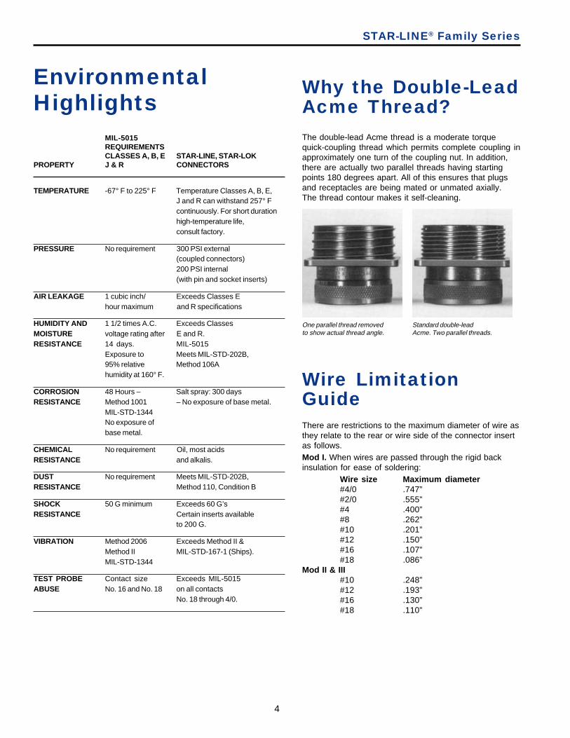
The double-lead Acme thread is a moderate torquequick-coupling thread which permits complete coupling inapproximately one turn of the coupling nut. In addition,there are actually two parallel threads having startingpoints 180 degrees apart. All of this ensures that plugsand receptacles are being mated or unmated axially.The thread contour makes it self-cleaning.
STAR-LINE® Family Series
MIL-5015REQUIREMENTSCLASSES A, B, E STAR-LINE, STAR-LOK
PROPERTY J & R CONNECTORS
TEMPERATURE -67° F to 225° F Temperature Classes A, B, E,J and R can withstand 257° Fcontinuously. For short durationhigh-temperature life,consult factory.
PRESSURE No requirement 300 PSI external(coupled connectors)200 PSI internal(with pin and socket inserts)
AIR LEAKAGE 1 cubic inch/ Exceeds Classes Ehour maximum and R specifications
HUMIDITY AND 1 1/2 times A.C. Exceeds ClassesMOISTURE voltage rating after E and R.RESISTANCE 14 days. MIL-5015
Exposure to Meets MIL-STD-202B,95% relative Method 106Ahumidity at 160° F.
CORROSION 48 Hours – Salt spray: 300 daysRESISTANCE Method 1001 – No exposure of base metal.
MIL-STD-1344No exposure ofbase metal.
CHEMICAL No requirement Oil, most acidsRESISTANCE and alkalis.
DUST No requirement Meets MIL-STD-202B,RESISTANCE Method 110, Condition B
SHOCK 50 G minimum Exceeds 60 G’sRESISTANCE Certain inserts available
to 200 G.
VIBRATION Method 2006 Exceeds Method II &Method II MIL-STD-167-1 (Ships).MIL-STD-1344
TEST PROBE Contact size Exceeds MIL-5015ABUSE No. 16 and No. 18 on all contacts
No. 18 through 4/0.
Why the Double-LeadAcme Thread?
There are restrictions to the maximum diameter of wire asthey relate to the rear or wire side of the connector insertas follows.Mod I. When wires are passed through the rigid backinsulation for ease of soldering:
Wire size Maximum diameter#4/0 .747”#2/0 .555”#4 .400”#8 .262”#10 .201”#12 .150”#16 .107”#18 .086”
Mod II & III#10 .248”#12 .193”#16 .130”#18 .110”
Wire LimitationGuide
One parallel thread removedto show actual thread angle.
Standard double-leadAcme. Two parallel threads.
AmphenolINDUSTRIAL
5
PressurizingSleeve
Green
Contact Seal
InsertSeal
Shell SealAdapter Seal Adapter Washer
Red
Cable Adapter
Coupling Nut
Plug Barrel
Rigid Insulator
Double LeadAcme Thread
Resilient Insulator
Receptacle Barrel
Pressure Sleeve
PressurePad
Double Lead Acme Thread
Shell SealAdapter Seal Adapter
Washer
PressurePad
Cable Adapter
Coupling Nut
Plug Shell
Rigid Front Insulator
Resilient Contact Seal Laminant
Rigid Rear Insulator
ReceptacleShell
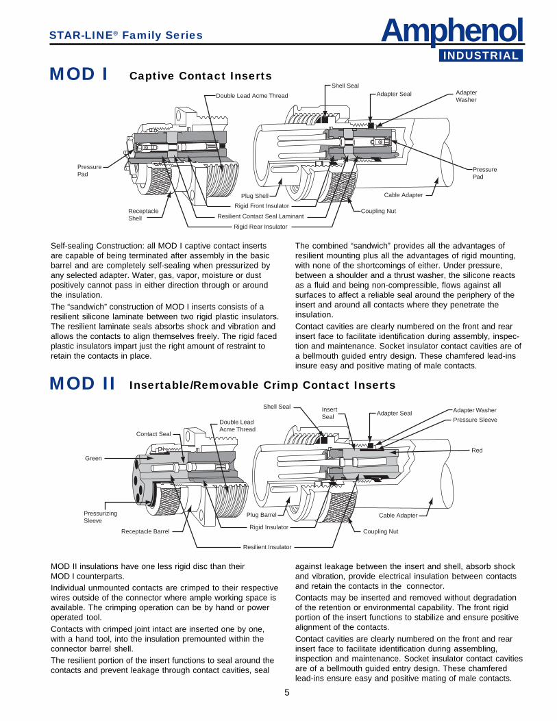
MOD II insulations have one less rigid disc than theirMOD I counterparts.Individual unmounted contacts are crimped to their respectivewires outside of the connector where ample working space isavailable. The crimping operation can be by hand or poweroperated tool.Contacts with crimped joint intact are inserted one by one,with a hand tool, into the insulation premounted within theconnector barrel shell.The resilient portion of the insert functions to seal around thecontacts and prevent leakage through contact cavities, seal
The combined “sandwich” provides all the advantages ofresilient mounting plus all the advantages of rigid mounting,with none of the shortcomings of either. Under pressure,between a shoulder and a thrust washer, the silicone reactsas a fluid and being non-compressible, flows against allsurfaces to affect a reliable seal around the periphery of theinsert and around all contacts where they penetrate theinsulation.Contact cavities are clearly numbered on the front and rearinsert face to facilitate identification during assembly, inspec-tion and maintenance. Socket insulator contact cavities are ofa bellmouth guided entry design. These chamfered lead-insinsure easy and positive mating of male contacts.
Self-sealing Construction: all MOD I captive contact insertsare capable of being terminated after assembly in the basicbarrel and are completely self-sealing when pressurized byany selected adapter. Water, gas, vapor, moisture or dustpositively cannot pass in either direction through or aroundthe insulation.The “sandwich” construction of MOD I inserts consists of aresilient silicone laminate between two rigid plastic insulators.The resilient laminate seals absorbs shock and vibration andallows the contacts to align themselves freely. The rigid facedplastic insulators impart just the right amount of restraint toretain the contacts in place.
STAR-LINE® Family Series
against leakage between the insert and shell, absorb shockand vibration, provide electrical insulation between contactsand retain the contacts in the connector.Contacts may be inserted and removed without degradationof the retention or environmental capability. The front rigidportion of the insert functions to stabilize and ensure positivealignment of the contacts.Contact cavities are clearly numbered on the front and rearinsert face to facilitate identification during assembling,inspection and maintenance. Socket insulator contact cavitiesare of a bellmouth guided entry design. These chamferedlead-ins ensure easy and positive mating of male contacts.
Captive Contact InsertsMOD I
Insertable/Removable Crimp Contact InsertsMOD II
6
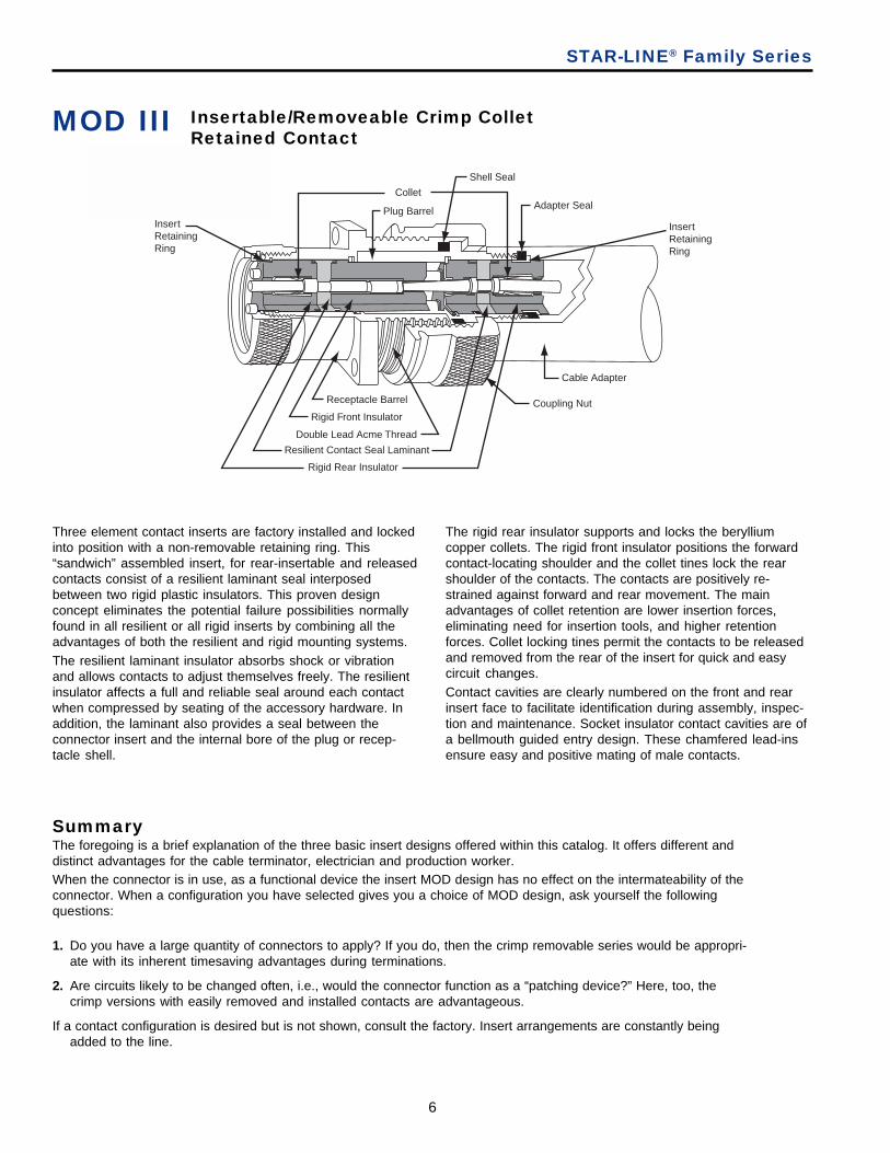
Insertable/Removeable Crimp ColletRetained Contact
SummaryThe foregoing is a brief explanation of the three basic insert designs offered within this catalog. It offers different anddistinct advantages for the cable terminator, electrician and production worker.When the connector is in use, as a functional device the insert MOD design has no effect on the intermateability of theconnector. When a configuration you have selected gives you a choice of MOD design, ask yourself the followingquestions:
1. Do you have a large quantity of connectors to apply? If you do, then the crimp removable series would be appropri-ate with its inherent timesaving advantages during terminations.
2. Are circuits likely to be changed often, i.e., would the connector function as a “patching device?” Here, too, thecrimp versions with easily removed and installed contacts are advantageous.
If a contact configuration is desired but is not shown, consult the factory. Insert arrangements are constantly beingadded to the line.
Three element contact inserts are factory installed and lockedinto position with a non-removable retaining ring. This“sandwich” assembled insert, for rear-insertable and releasedcontacts consist of a resilient laminant seal interposedbetween two rigid plastic insulators. This proven designconcept eliminates the potential failure possibilities normallyfound in all resilient or all rigid inserts by combining all theadvantages of both the resilient and rigid mounting systems.The resilient laminant insulator absorbs shock or vibrationand allows contacts to adjust themselves freely. The resilientinsulator affects a full and reliable seal around each contactwhen compressed by seating of the accessory hardware. Inaddition, the laminant also provides a seal between theconnector insert and the internal bore of the plug or recep-tacle shell.
The rigid rear insulator supports and locks the berylliumcopper collets. The rigid front insulator positions the forwardcontact-locating shoulder and the collet tines lock the rearshoulder of the contacts. The contacts are positively re-strained against forward and rear movement. The mainadvantages of collet retention are lower insertion forces,eliminating need for insertion tools, and higher retentionforces. Collet locking tines permit the contacts to be releasedand removed from the rear of the insert for quick and easycircuit changes.Contact cavities are clearly numbered on the front and rearinsert face to facilitate identification during assembly, inspec-tion and maintenance. Socket insulator contact cavities are ofa bellmouth guided entry design. These chamfered lead-insensure easy and positive mating of male contacts.
STAR-LINE® Family Series
MOD III
Shell Seal
Adapter Seal
Cable Adapter
Coupling Nut
Plug Barrel
Rigid Front Insulator
Double Lead Acme Thread
Resilient Contact Seal Laminant
Rigid Rear Insulator
Collet
InsertRetainingRing
InsertRetainingRing
Receptacle Barrel

AmphenolINDUSTRIAL
7
Ordering InformationAll plug and receptacle assemblies require two part numbers:A. The catalog number of the desired insert.B. The catalog number of the selected plug or receptacle hardware.
To Order Complete Assemblies1. Determine supply voltage, amperage and number of contacts desired.
2. Select insert configuration from pages 37-63. Write down Dash Number, Shell Size and MOD number ofinsert. Voltage and amperage information can be found on page 30. Example: 3#12 contacts – 27P (MALE)and 27S (FEMALE); MOD I; Shell Size 12 (page 37).
3. Select desired plug and receptacle hardware from pages 9-28. Make certain that the shell size of thehardware corresponds with the shell size of the desired insert. Determine outside diameter of cable. Ex-ample: Male Plug with Basket Weave. Cable is 3 conductor #12 (.635 outside diameter). ZPLK-1212-27P(page 15).
Female Receptacle mounted to Junction Box with 45° Angle Adapter and 1” Conduit Hub. ZRLBB-312-27S(page 23).
4. Order tools from pages 76-77.
Power Connectors – 20-30-60-100-200-325-700 Amperes, 1 thru 10 Contacts
Control & Instrumentation Connectors – 3 thru 143 Contacts
The following pages present connector sub-assemblies which are available and can be used in conjunction with theinserts listed.
Custom BuildYour Own Connectors
To Order Assemblies Without The Insert(For large users stocking connector components in bulk)
1. If a MOD I insert will be used, order the hardware by the catalog number and eliminate the asterisk.Example: ZPLD-1212 (page 12).
2. If a MOD II insert will be used, order by the catalog number but substitute a 200 for the asterisk.Example: ZPLD-1212-200
3. MOD III inserts must be ordered assembled in their basic barrel (consult Amphenol Industrial Operations).
PIN INSERTCONFIGURATION
PLUGCONFIGURATION
RECEPTACLECONFIGURATION
SOCKET INSERTCONFIGURATION
STAR-LINE® Family Series

8
Connector Assemblies
1. Hardware with a longer cable housing should be used ifthe insert has:
A. Any pressure contact – line or ground.B. More than 10 contacts-any size.C. More than 4 #10 or larger contacts.
2. A jack coupling nut should be used if the insert has:A. A configuration with shorter relay contacts.B. A configuration of 37 or more contacts.
A JACK COUPLING NUT SHOULD NOT BE USED ONANY POWER INSERT CONNECTOR THAT IS TO BEDISCONNECTED UNDER LOAD
Shell Size Torque Setting (lb. ft.)12 11,016 13.520 15.5
C20 15.524 23.0
C24 23.028 31.0
C28 31.0
NOTE: The N.E.C. circuit breaking and non-circuit breakingratings are based on test results of contacts and connectors.Consult the N.E.C. when selecting wire/cable for specificapplications. Under certain conditions, a wire size may be ratedhigher or lower than our table indicates for a given contact size.
Please Read Carefully:
Typical MOD I Plug Components
Typical MOD I Receptacle Components
3. To insure proper coupling the following torque valuesshould be used on the coupling nut:
STAR-LINE® Family Series
ENVIRONMENTALCOVER - FEMALE
FLANGEGASKET
SOCKETCONTACTS
INSERTCLAMP NUT
SQUARE FLANGERECEPTACLE
FEMALEINSERT
MECHANICALCLAMP NUT GROMMET
MALEINSERT
COUPLINGNUT
ENVIRONMENTALCOVER - MALE
WASHER CABLE ADAPTER PINCONTACTS
MALESKIRT
AmphenolINDUSTRIAL
9
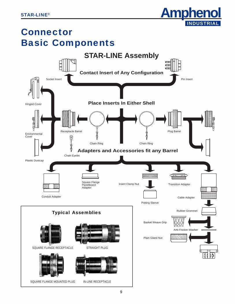
STAR-LINE Assembly
Contact Insert of Any Configuration
Place Inserts In Either Shell
Adapters and Accessories fit any Barrel
Hinged Cover
Socket Insert Pin Insert
EnvironmentalCover
Plastic Dustcap
Conduit Adapter
Square FlangePanelboardAdapter
Chain Eyelet
Receptacle Barrel Plug Barrel
Chain Ring Chain Ring
Potting Sleeve
Basket Weave Grip
Anti-Friction Washer
Plain Gland Nut
Cable Adapter
Rubber Grommet
Transition AdapterInsert Clamp Nut
SQUARE FLANGE RECEPTACLE STRAIGHT PLUG
SQUARE FLANGE MOUNTED PLUG IN-LINE RECEPTACLE
ConnectorBasic Components
Typical Assemblies
STAR-LINE®
10
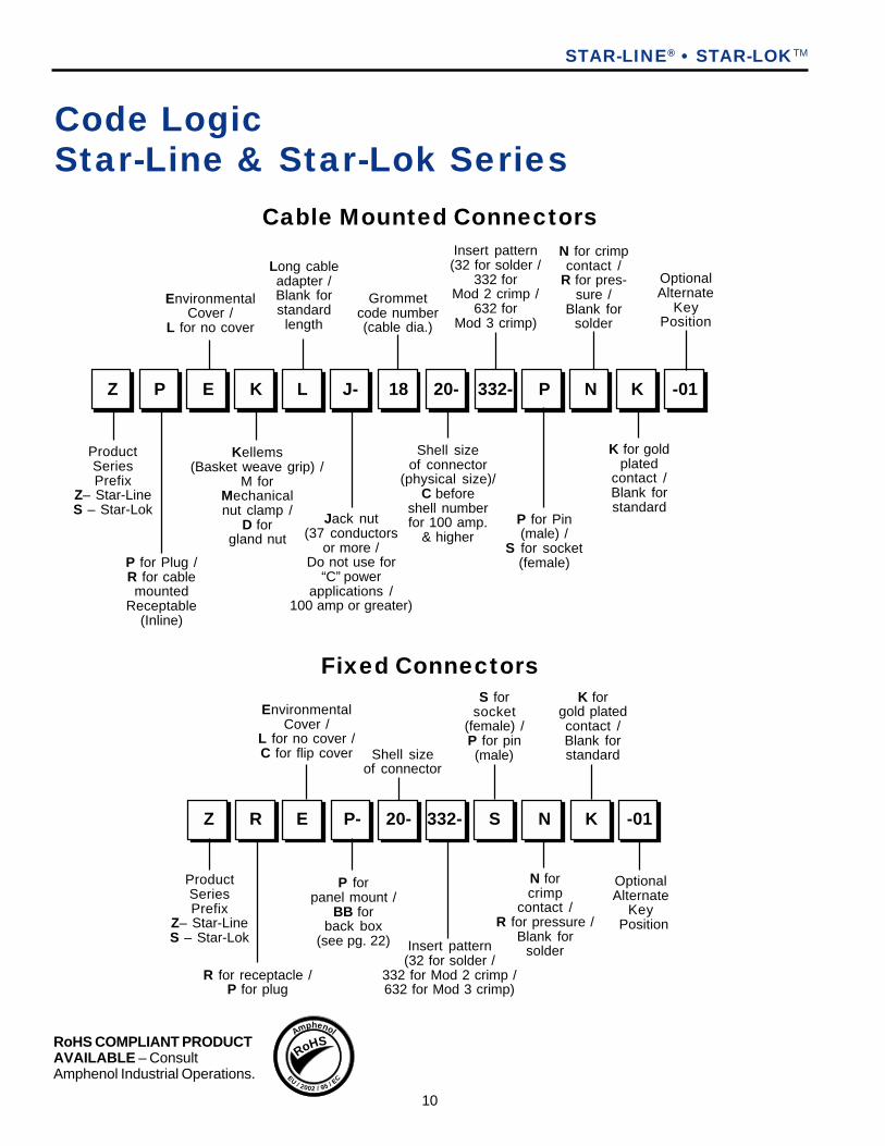
Code LogicStar-Line & Star-Lok Series
Kellems(Basket weave grip) /
M forMechanicalnut clamp /
D forgland nut
332-Z P E K L J- 18 20- P N K -01
ProductSeriesPrefix
Z– Star-LineS – Star-Lok
P for Plug /R for cablemounted
Receptable(Inline)
EnvironmentalCover /
L for no cover
Long cableadapter /Blank forstandard
length
Jack nut(37 conductors
or more /Do not use for
“C” powerapplications /
100 amp or greater)
Grommetcode number(cable dia.)
Shell sizeof connector
(physical size)/C before
shell numberfor 100 amp.
& higher
Insert pattern(32 for solder /
332 forMod 2 crimp /
632 forMod 3 crimp)
P for Pin(male) /
S for socket(female)
N for crimpcontact /
R for pres-sure /
Blank forsolder
K for goldplated
contact /Blank forstandard
OptionalAlternate
KeyPosition
Cable Mounted Connectors
P forpanel mount /
BB forback box
(see pg. 22)
Z R E P- 20- 332- S N K -01
R for receptacle /P for plug
EnvironmentalCover /
L for no cover /C for flip cover
Insert pattern(32 for solder /
332 for Mod 2 crimp /632 for Mod 3 crimp)
Fixed ConnectorsS for
socket(female) /P for pin(male)
N forcrimp
contact /R for pressure /
Blank forsolder
K forgold platedcontact /Blank forstandard
OptionalAlternate
Key Position
STAR-LINE® • STAR-LOKTM
ProductSeriesPrefix
Z– Star-LineS – Star-Lok
Shell sizeof connector
RoHS COMPLIANT PRODUCTAVAILABLE – ConsultAmphenol Industrial Operations.
RoHSAmphenol
EU/ 2002 / 95 / EC
AmphenolINDUSTRIAL
11
Contact Insert of Any Configuration
Place Inserts In Either Shell
Adapters and Accessories fit any Barrel
PlasticDust Cap
EnvironmentalCover
Socket Insert Pin Insert
Back BoxAdapter
Chain EyeletPanelReceptacle
Plug Barreland Coupling Unit
Chain Ring
Potting Sleeve
Basket Weave Grip Anti-FrictionWasher
Plain Gland Nut
Mechanical ClampNut
Cable Adapter
Rubber Grommet
Transition AdapterInsert Clamp Nut
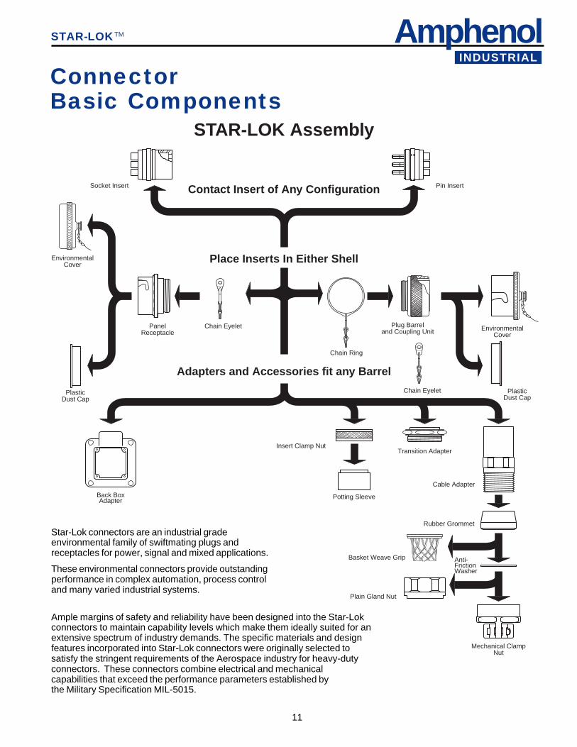
STAR-LOK Assembly
Chain Eyelet
EnvironmentalCover
PlasticDust Cap
Star-Lok connectors are an industrial gradeenvironmental family of swiftmating plugs andreceptacles for power, signal and mixed applications.
These environmental connectors provide outstandingperformance in complex automation, process controland many varied industrial systems.
Ample margins of safety and reliability have been designed into the Star-Lokconnectors to maintain capability levels which make them ideally suited for anextensive spectrum of industry demands. The specific materials and designfeatures incorporated into Star-Lok connectors were originally selected tosatisfy the stringent requirements of the Aerospace industry for heavy-dutyconnectors. These connectors combine electrical and mechanicalcapabilities that exceed the performance parameters established bythe Military Specification MIL-5015.
ConnectorBasic Components
STAR-LOKTM
12
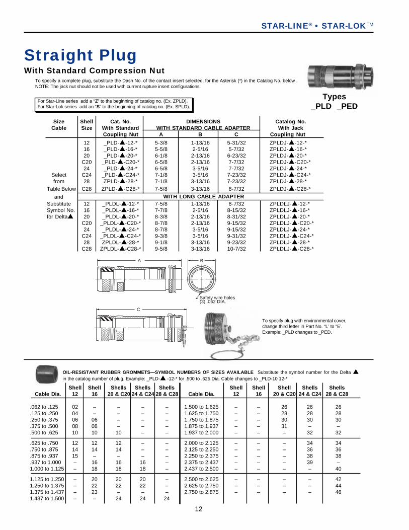
Size Shell Cat. No. DIMENSIONS Catalog No.Cable Size With Standard WITH STANDARD CABLE ADAPTER With Jack
Coupling Nut A B C Coupling Nut
12 _PLD-▲-12-* 5-3/8 1-13/16 5-31/32 ZPLDJ-▲-12-*16 _PLD-▲-16-* 5-5/8 2-5/16 5-7/32 ZPLDJ-▲-16-*20 _PLD-▲-20-* 6-1/8 2-13/16 6-23/32 ZPLDJ-▲-20-*
C20 _PLD-▲-C20-* 6-5/8 2-13/16 7-7/32 ZPLDJ-▲-C20-*24 _PLD-▲-24-* 6-5/8 3-5/16 7-7/32 ZPLDJ-▲-24-*
Select C24 _PLD-▲-C24-* 7-1/8 3-5/16 7-23/32 ZPLDJ-▲-C24-*from 28 ZPLD-▲-28-* 7-1/8 3-13/16 7-23/32 ZPLDJ-▲-28-*
Table Below C28 ZPLD-▲-C28-* 7-5/8 3-13/16 8-7/32 ZPLDJ-▲-C28-*
andSubstitute 12 _PLDL-▲-12-* 7-5/8 1-13/16 8-7/32 ZPLDLJ-▲-12-*Symbol No. 16 _PLDL-▲-16-* 7-7/8 2-5/16 8-15/32 ZPLDLJ-▲-16-*for Delta▲ 20 _PLDL-▲-20-* 8-3/8 2-13/16 8-31/32 ZPLDLJ-▲-20-*
C20 _PLDL-▲-C20-* 8-7/8 2-13/16 9-15/32 ZPLDLJ-▲-C20-*24 _PLDL-▲-24-* 8-7/8 3-5/16 9-15/32 ZPLDLJ-▲-24-*
C24 _PLDL-▲-C24-* 9-3/8 3-5/16 9-31/32 ZPLDLJ-▲-C24-*28 ZPLDL-▲-28-* 9-1/8 3-13/16 9-23/32 ZPLDLJ-▲-28-*
C28 ZPLDL-▲-C28-* 9-5/8 3-13/16 10-7/32 ZPLDLJ-▲-C28-*
Straight PlugWith Standard Compression Nut
To specify plug with environmental cover,change third letter in Part No. “L’ to “E’.Example: _PLD changes to _PED.
Shell Shell Shells Shells Shells Shell Shell Shell Shells ShellsCable Dia. 12 16 20 & C20 24 & C24 28 & C28 Cable Dia. 12 16 20 & C20 24 & C24 28 & C28
.062 to .125 02 – – – – 1.500 to 1.625 – – 26 26 26
.125 to .250 04 – – – – 1.625 to 1.750 – – 28 28 28
.250 to .375 06 06 – – – 1.750 to 1.875 – – 30 30 30
.375 to .500 08 08 – – – 1.875 to 1.937 – – 31 – –
.500 to .625 10 10 10 – – 1.937 to 2.000 – – – 32 32
.625 to .750 12 12 12 – – 2.000 to 2.125 – – – 34 34
.750 to .875 14 14 14 – – 2.125 to 2.250 – – – 36 36
.875 to .937 15 – – – – 2.250 to 2.375 – – – 38 38
.937 to 1.000 – 16 16 16 – 2.375 to 2.437 – – – 39 –1.000 to 1.125 – 18 18 18 – 2.437 to 2.500 – – – – 40
1.125 to 1.250 – 20 20 20 – 2.500 to 2.625 – – – – 421.250 to 1.375 – 22 22 22 – 2.625 to 2.750 – – – – 441.375 to 1.437 – 23 – – – 2.750 to 2.875 – – – – 461.437 to 1.500 – – 24 24 24
OIL-RESISTANT RUBBER GROMMETS—SYMBOL NUMBERS OF SIZES AVAILABLE Substitute the symbol number for the Delta ▲in the catalog number of plug. Example: _PLD-▲ -12-* for .500 to .625 Dia. Cable changes to _PLD-10 12-*
To specify a complete plug, substitute the Dash No. of the contact insert selected, for the Asterisk (*) in the Catalog No. below .NOTE: The jack nut should not be used with current rupture insert configurations.
WITH LONG CABLE ADAPTER
For Star-Line series add a “Z” to the beginning of catalog no. (Ex. ZPLD).For Star-Lok series add an “S” to the beginning of catalog no. (Ex. SPLD).
Types_PLD _PED
A B
Safety wire holes(3) .062 DIA.
C
STAR-LINE® • STAR-LOKTM
13
AmphenolINDUSTRIAL
C
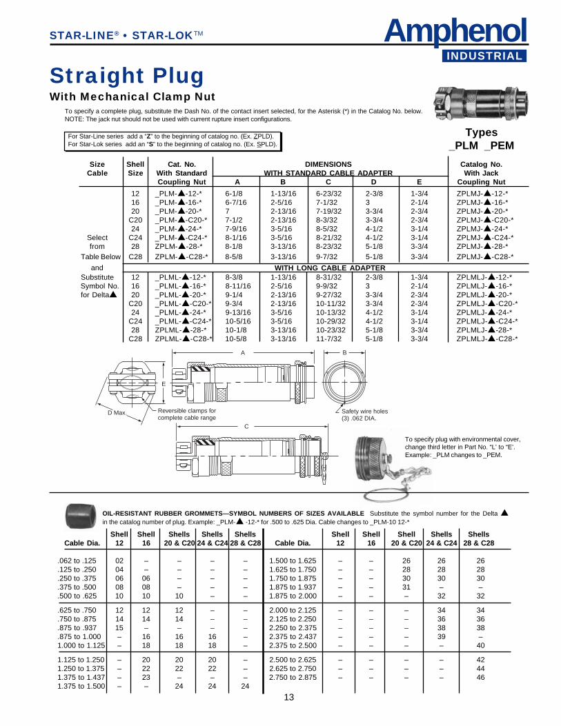
Size Shell Cat. No. DIMENSIONS Catalog No.Cable Size With Standard WITH STANDARD CABLE ADAPTER With Jack
Coupling Nut A B C D E Coupling Nut
12 _PLM-▲-12-* 6-1/8 1-13/16 6-23/32 2-3/8 1-3/4 ZPLMJ-▲-12-*16 _PLM-▲-16-* 6-7/16 2-5/16 7-1/32 3 2-1/4 ZPLMJ-▲-16-*20 _PLM-▲-20-* 7 2-13/16 7-19/32 3-3/4 2-3/4 ZPLMJ-▲-20-*
C20 _PLM-▲-C20-* 7-1/2 2-13/16 8-3/32 3-3/4 2-3/4 ZPLMJ-▲-C20-*24 _PLM-▲-24-* 7-9/16 3-5/16 8-5/32 4-1/2 3-1/4 ZPLMJ-▲-24-*
Select C24 _PLM-▲-C24-* 8-1/16 3-5/16 8-21/32 4-1/2 3-1/4 ZPLMJ-▲-C24-*from 28 ZPLM-▲-28-* 8-1/8 3-13/16 8-23/32 5-1/8 3-3/4 ZPLMJ-▲-28-*
Table Below C28 ZPLM-▲-C28-* 8-5/8 3-13/16 9-7/32 5-1/8 3-3/4 ZPLMJ-▲-C28-*
andSubstitute 12 _PLML-▲-12-* 8-3/8 1-13/16 8-31/32 2-3/8 1-3/4 ZPLMLJ-▲-12-*Symbol No. 16 _PLML-▲-16-* 8-11/16 2-5/16 9-9/32 3 2-1/4 ZPLMLJ-▲-16-*for Delta▲ 20 _PLML-▲-20-* 9-1/4 2-13/16 9-27/32 3-3/4 2-3/4 ZPLMLJ-▲-20-*
C20 _PLML-▲-C20-* 9-3/4 2-13/16 10-11/32 3-3/4 2-3/4 ZPLMLJ-▲-C20-*24 _PLML-▲-24-* 9-13/16 3-5/16 10-13/32 4-1/2 3-1/4 ZPLMLJ-▲-24-*
C24 _PLML-▲-C24-* 10-5/16 3-5/16 10-29/32 4-1/2 3-1/4 ZPLMLJ-▲-C24-*28 ZPLML-▲-28-* 10-1/8 3-13/16 10-23/32 5-1/8 3-3/4 ZPLMLJ-▲-28-*
C28 ZPLML-▲-C28-* 10-5/8 3-13/16 11-7/32 5-1/8 3-3/4 ZPLMLJ-▲-C28-*
Straight PlugWith Mechanical Clamp Nut
To specify plug with environmental cover,change third letter in Part No. “L’ to “E’.Example: _PLM changes to _PEM.
Shell Shell Shells Shells Shells Shell Shell Shell Shells ShellsCable Dia. 12 16 20 & C20 24 & C24 28 & C28 Cable Dia. 12 16 20 & C20 24 & C24 28 & C28
.062 to .125 02 – – – – 1.500 to 1.625 – – 26 26 26
.125 to .250 04 – – – – 1.625 to 1.750 – – 28 28 28
.250 to .375 06 06 – – – 1.750 to 1.875 – – 30 30 30
.375 to .500 08 08 – – – 1.875 to 1.937 – – 31 – –
.500 to .625 10 10 10 – – 1.875 to 2.000 – – – 32 32
.625 to .750 12 12 12 – – 2.000 to 2.125 – – – 34 34
.750 to .875 14 14 14 – – 2.125 to 2.250 – – – 36 36
.875 to .937 15 – – – – 2.250 to 2.375 – – – 38 38
.875 to 1.000 – 16 16 16 – 2.375 to 2.437 – – – 39 –1.000 to 1.125 – 18 18 18 – 2.375 to 2.500 – – – – 40
1.125 to 1.250 – 20 20 20 – 2.500 to 2.625 – – – – 421.250 to 1.375 – 22 22 22 – 2.625 to 2.750 – – – – 441.375 to 1.437 – 23 – – – 2.750 to 2.875 – – – – 461.375 to 1.500 – – 24 24 24
OIL-RESISTANT RUBBER GROMMETS—SYMBOL NUMBERS OF SIZES AVAILABLE Substitute the symbol number for the Delta ▲in the catalog number of plug. Example: _PLM-▲ -12-* for .500 to .625 Dia. Cable changes to _PLM-10 12-*
To specify a complete plug, substitute the Dash No. of the contact insert selected, for the Asterisk (*) in the Catalog No. below.NOTE: The jack nut should not be used with current rupture insert configurations.
WITH LONG CABLE ADAPTER
For Star-Line series add a “Z” to the beginning of catalog no. (Ex. ZPLD).For Star-Lok series add an “S” to the beginning of catalog no. (Ex. SPLD).
Types_PLM _PEM
STAR-LINE® • STAR-LOKTM
A
D Max. Reversible clamps forcomplete cable range
E
B
Safety wire holes(3) .062 DIA.

14
C
B
G SQ.
Safety Wire Holes (3) .062 Dia.
A
H SQ.
J Hole Dia.
Straight PlugWith Conduit Adapter (for flexible conduit fittings)To specify a complete plug, substitute the dash no. of the contact insert selected for the asterisk (*)In the catalog no. below. NOTE: The jack nut should not be used with current rupture insert configurations.A PLUG WITH JACK COUPLING NUT SHOULD BE USED WITH INSERTS HAVING 37 OR MORE CONTACTS.
Shell Open Catalog No. DIMENSIONS Catalog No.Size Back With Standard With Jack
Coupling Nut A B C G H J Coupling Nut12 ZPLP-12-* 2-3/8 1-13/16 2-31/32 1-17/64 1-5/8 3/16 ZPLPJ- 12-*16 ZPLP-16-* 2-13/32 2-5/16 3 1-11/16 2-1/8 7/32 ZPLPJ- 16-*20 ZPLP-20-* 2-7/16 2-13/16 3-1/32 2-3/32 2-5/8 9/32 ZPLPJ- 20-*C20 ZPLP-C20-* 2-15/16 2-13/16 3-17/32 2-3/32 2-5/8 9/32 ZPLPJ- C20-*24 ZPLP-24-* 2-15/32 3-5/16 3-1/16 2-17/32 3-1/8 11/32 ZPLPJ- 24-*C24 ZPLP-C24-* 2-31/32 3-5/16 3-9/16 2-17/32 3-1/8 11/32 ZPLPJ- C24-*28 ZPLP-28-* 2-15/32 3-13/16 3-1/16 3-1/32 3-3/4 11/32 ZPLPJ- 28-*C28 ZPLP-C28-* 2-31/32 3-13/16 3-9/16 3-1/32 3-3/4 11/32 ZPLPJ- C28-*
Use withor without
PottingSleeve
To specify plug with environmental cover,change third letter in Part No. “L” to “E”.Example: _PLT changes to _PET.
Shell Size Catalog No. Catalog No.Size Conduit With Standard With Jack
Coupling Nut A B C D Coupling Nut12 3/4 _PLT-2 12-* 4-1/4 1-13/16 4-27-32 3/4 ZPLTJ-2 12-*16 1-1/4 _PLT-4 16-* 4-3/8 2-5/16 4-31/32 1-1/4 ZPLTJ-4 16-*20 1-1/2 _PLT-5 20-* 4-1/2 2-13/16 5-3/32 1-1/2 ZPLTJ-5 20-*C20 1-1/2 _PLT-5 C20-* 5 2-13/16 5-19/32 1-1/2 ZPLTJ-5 C20-*24 2 _PLT-6 24-* 4-5/8 3-5/16 5-7/32 2 ZPLTJ-6 24-*C24 2 _PLT-6 C24-* 5-1/8 3-5/16 5-23/32 2 ZPLTJ-6 C24-*28 2-1/2 ZPLT-7 28-* 5-3/32 3-13/16 5-11/16 2-1/2 ZPLTJ-7 28-*C28 2-1/2 ZPLT-7 C28-* 5-19/32 3-13/16 6-3/16 2-1/2 ZPLTJ-7 C28-*
DIMENSIONS
For Star-Line series add a “Z” to the beginning of catalog no. (Ex. ZPLT). For Star-Lok series add an “S” to the beginning of catalog no. (Ex. SPLT).
Types_PLT _PET
STAR-LINE® • STAR-LOKTM
A
DNPT Thread Size
B
Safety Wire Holes(3) .062 DIA.C
Straight Male PlugPanel Mount (Not available in Star-Lok)To specify a complete plug, substitute the dash no. of the contact insert selected for the asterisk (*) in the catalog no. below.NOTE The jack nut should not be used with current rupture insert configurationsA PLUG WITH JACK COUPLING NUT SHOULD BE USED WITH INSERTS HAVING 37 OR MORE CONTACTS.
TypesZPLP ZPEP
To specify plug with environmental cover,change third letter in Part No. “L” to “E”.Example: ZPLP changes to ZPEP.

15
AmphenolINDUSTRIAL
Shell Shell Shells Shells Shells Shell Shell Shell Shells ShellsCable Dia. 12 16 20 & C20 24 & C24 28 & C28 Cable Dia. 12 16 20 & C20 24 & C24 28 & C28
.062 to .125 02 – – – – 1.500 to 1.625 – – 26 26 26
.125 to .250 04 – – – – 1.625 to 1.750 – – 28 28 28
.250 to .375 06 06 – – – 1.750 to 1.875 – – 30 30 30
.375 to .500 08 08 – – – 1.875 to 1.937 – – 31 – –
.500 to .625 10 10 10 – – 1.875 to 2.000 – – – 32 32
.625 to .750 12 12 12 – – 2.000 to 2.125 – – – 34 34
.750 to .875 14 14 14 – – 2.125 to 2.250 – – – 36 36
.875 to .937 15 – – – – 2.250 to 2.375 – – – 38 38
.875 to 1.000 – 16 16 16 – 2.375 to 2.437 – – – 39 –1.000 to 1.125 – 18 18 18 – 2.437 to 2.500 – – – – 40
1.125 to 1.250 – 20 20 20 – 2.500 to 2.625 – – – – 421.250 to 1.375 – 22 22 22 – 2.625 to 2.750 – – – – 441.375 to 1.437 – 23 – – – 2.750 to 2.875 – – – – 461.375 to 1.500 – – 24 24 24
12 _PLKL-▲-12-* 7-5/8 1-13/16 8-7/32 ZPLKJ-▲-12-*16 _PLKL-▲-16-* 7-7/8 2-5/16 8-15/32 ZPLKJ-▲-16-*20 _PLKL-▲-20-* 8-3/8 2-13/16 8-31/32 ZPLKJ-▲-20-*C20 _PLKL-▲-C20-* 8-7/8 2-13/16 9-15/32 ZPLKJ-▲-C20-*24 _PLKL-▲-24-* 8-7/8 3-5/16 9-15/32 ZPLKJ-▲-24-*C24 _PLKL-▲-C24-* 9-3/8 3-5/16 9-31/32 ZPLKJ-▲-C24-*28 ZPLKL-▲-28-* 9-1/8 3-13/16 9-23/32 ZPLKJ-▲-28-*C28 ZPLKL-▲-C28-* 9-5/8 3-13/16 10-7/32 ZPLKJ-▲-C28-*
Selectfrom
Table Belowand
SubstituteSymbol No.for Delta ▲
WITH LONG CABLE ADAPTER
For Star-Line series add a “Z” to the beginning of catalog no. (Ex. ZPLK). For Star-Lok series add an “S” to the beginning of catalog no. (Ex. SPLK).
STAR-LINE® • STAR-LOKTM
Types_PLK _PEK
B
Safety wire holes(3) .062 DIA.
ASee cable gripcomponents pagefor basket weave grip lengths
C
Size Shell Catalog No. DIMENSIONS Catalog No.Cable Size With Standard WITH STANDARD CABLE ADAPTER With Jack
Coupling Nut A B C Coupling Nut12 _PLK-▲-12-* 5-3/8 1-13/16 5-31/32 ZPLKJ-▲-12-*16 _PLK-▲-16-* 5-5/8 2-5/16 6-7/32 ZPLKJ-▲-16-*20 _PLK-▲-20-* 6-1/8 2-13/16 6-23/32 ZPLKJ-▲-20-*C20 _PLK-▲-C20-* 6-5/8 2-13/16 7-7/32 ZPLKJ-▲-C20-*24 _PLK-▲-24-* 6-5/8 3-5/16 7-7/32 ZPLKJ-▲-24-*C24 _PLK-▲-C24-* 7-1/8 3-5/16 7-23/32 ZPLKJ-▲-C24-*28 ZPLK-▲-28-* 7-1/8 3-13/16 7-23/32 ZPLKJ-▲-28-*C28 ZPLK-▲-C28-* 7-5/8 3-13/16 8-7/32 ZPLKJ-▲-C28-*
Straight PlugWith Basketweave Cable GripTo specify a complete plug, substitute the Dash No. of the contact insert selected for the asterisk (*) in the catalog no. below.NOTE: The jack nut should not be used with current rupture insert configurations.A PLUG WITH JACK COUPLING NUT SHOULD BE USED WITH INSERTS HAVING 37 OR MORE CONTACTS
To specify plug with environmental cover,change third letter in Part No. “L” to “E”.Example: _PLK changes to _PEK.
OIL-RESISTANT RUBBER GROMMETS—SYMBOL NUMBERS OF SIZES AVAILABLE Substitute the symbol number for theDelta ▲ in the catalog number of plug. Example: _PLK-▲ -12-* for .500 to .625 Dia. Cable changes to _PLK-10 12-*
16
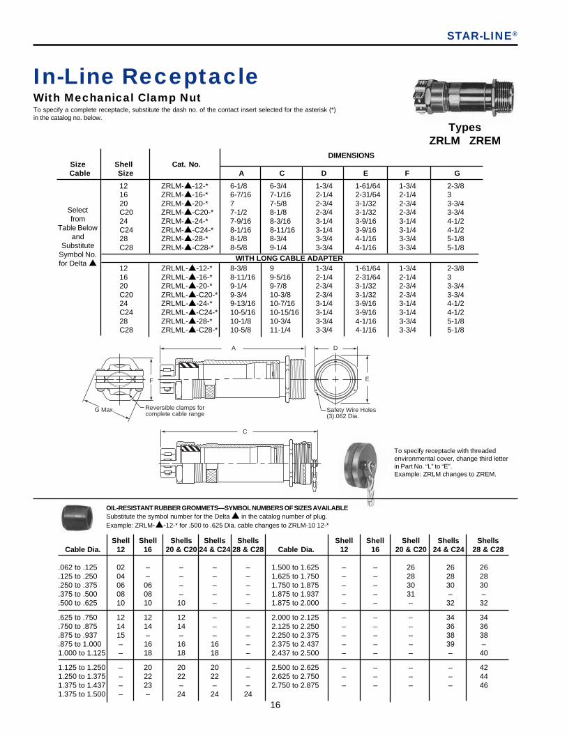
In-Line ReceptacleWith Mechanical Clamp NutTo specify a complete receptacle, substitute the dash no. of the contact insert selected for the asterisk (*)in the catalog no. below.
OIL-RESISTANT RUBBER GROMMETS—SYMBOL NUMBERS OF SIZES AVAILABLESubstitute the symbol number for the Delta ▲ in the catalog number of plug.Example: ZRLM-▲-12-* for .500 to .625 Dia. cable changes to ZRLM-10 12-*
Shell Shell Shells Shells Shells Shell Shell Shell Shells Shells Cable Dia. 12 16 20 & C20 24 & C24 28 & C28 Cable Dia. 12 16 20 & C20 24 & C24 28 & C28
.062 to .125 02 – – – – 1.500 to 1.625 – – 26 26 26
.125 to .250 04 – – – – 1.625 to 1.750 – – 28 28 28
.250 to .375 06 06 – – – 1.750 to 1.875 – – 30 30 30
.375 to .500 08 08 – – – 1.875 to 1.937 – – 31 – –
.500 to .625 10 10 10 – – 1.875 to 2.000 – – – 32 32
.625 to .750 12 12 12 – – 2.000 to 2.125 – – – 34 34
.750 to .875 14 14 14 – – 2.125 to 2.250 – – – 36 36
.875 to .937 15 – – – – 2.250 to 2.375 – – – 38 38
.875 to 1.000 – 16 16 16 – 2.375 to 2.437 – – – 39 –1.000 to 1.125 – 18 18 18 – 2.437 to 2.500 – – – – 40
1.125 to 1.250 – 20 20 20 – 2.500 to 2.625 – – – – 421.250 to 1.375 – 22 22 22 – 2.625 to 2.750 – – – – 441.375 to 1.437 – 23 – – – 2.750 to 2.875 – – – – 461.375 to 1.500 – – 24 24 24
TypesZRLM ZREM
To specify receptacle with threadedenvironmental cover, change third letterin Part No. “L” to “E”.Example: ZRLM changes to ZREM.
STAR-LINE®
DIMENSIONSSize Shell Cat. No.Cable Size A C D E F G
12 ZRLM-▲-12-* 6-1/8 6-3/4 1-3/4 1-61/64 1-3/4 2-3/816 ZRLM-▲-16-* 6-7/16 7-1/16 2-1/4 2-31/64 2-1/4 320 ZRLM-▲-20-* 7 7-5/8 2-3/4 3-1/32 2-3/4 3-3/4C20 ZRLM-▲-C20-* 7-1/2 8-1/8 2-3/4 3-1/32 2-3/4 3-3/424 ZRLM-▲-24-* 7-9/16 8-3/16 3-1/4 3-9/16 3-1/4 4-1/2C24 ZRLM-▲-C24-* 8-1/16 8-11/16 3-1/4 3-9/16 3-1/4 4-1/228 ZRLM-▲-28-* 8-1/8 8-3/4 3-3/4 4-1/16 3-3/4 5-1/8C28 ZRLM-▲-C28-* 8-5/8 9-1/4 3-3/4 4-1/16 3-3/4 5-1/8
WITH LONG CABLE ADAPTER12 ZRLML-▲-12-* 8-3/8 9 1-3/4 1-61/64 1-3/4 2-3/816 ZRLML-▲-16-* 8-11/16 9-5/16 2-1/4 2-31/64 2-1/4 320 ZRLML-▲-20-* 9-1/4 9-7/8 2-3/4 3-1/32 2-3/4 3-3/4C20 ZRLML-▲-C20-* 9-3/4 10-3/8 2-3/4 3-1/32 2-3/4 3-3/424 ZRLML-▲-24-* 9-13/16 10-7/16 3-1/4 3-9/16 3-1/4 4-1/2C24 ZRLML-▲-C24-* 10-5/16 10-15/16 3-1/4 3-9/16 3-1/4 4-1/228 ZRLML-▲-28-* 10-1/8 10-3/4 3-3/4 4-1/16 3-3/4 5-1/8C28 ZRLML-▲-C28-* 10-5/8 11-1/4 3-3/4 4-1/16 3-3/4 5-1/8
Selectfrom
Table Belowand
SubstituteSymbol No.for Delta ▲
A
Safety Wire Holes(3).062 Dia.
D
E
G Max. Reversible clamps forcomplete cable range
F
C

17
AmphenolINDUSTRIAL
In-Line ReceptacleWith Standard Compression NutTo specify a complete receptacle, substitute the dash no. of the contact insert selected for the asterisk (*)in the catalog no. below.
DimensionsSize Shell Cat. No.Cable Size A C D E
12 ZRLD-▲- 12-* 5-3/8 6 1-3/4 1-61/6416 ZRLD-▲- 16-* 5-5/8 6-1/4 2-1/4 2-31/6420 ZRLD-▲- 20-* 6-1/8 6-3/4 2-3/4 3-1/32C20 ZRLD-▲- C20-* 6-5/8 7-1/4 2-3/4 3-1/3224 ZRLD-▲- 24-* 6-5/8 7-1/4 3-1/4 3-9/16C24 ZRLD-▲- C24-* 7-1/8 7-3/4 3-1/4 3-9/1628 ZRLD-▲- 28-* 7-1/8 7-3/4 3-3/4 4-1/16C28 ZRLD-▲- C28-* 7-5/8 8-1/4 3-3/4 4-1/16
12 ZRLDL-▲-12-* 7-5/8 8-1/4 1-3/4 1-61/6416 ZRLDL-▲-16-* 7-7/8 8-1/2 2-1/4 2-31/6420 ZRLDL-▲-20-* 8-3/8 9 2-3/4 3-1/32C20 ZRLDL-▲-C20-* 8-7/8 9-1/2 2-3/4 3-1/3224 ZRLDL-▲-24-* 8-7/8 9-1/2 3-1/4 3-9/16C24 ZRLDL-▲-C24-* 9-3/8 10 3-1/4 3-9/1628 ZRLDL-▲-28-* 9-1/8 9-3/4 3-3/4 4-1/16C28 ZRLDL-▲-C28-* 9-5/8 10-1/4 3-3/4 4-1/16
Shell Shell Shells Shells Shells Shell Shell Shell Shells ShellsCable Dia. 12 16 20 & C20 24 & C24 28 & C28 Cable Dia. 12 16 20 & C20 24 & C24 28 & C28
.062 to .125 02 – – – – 1.500 to 1.625 – – 26 26 26
.125 to .250 04 – – – – 1.625 to 1.750 – – 28 28 28
.250 to .375 06 06 – – – 1.750 to 1.875 – – 30 30 30
.375 to .500 08 08 – – – 1.875 to 1.937 – – 31 – –
.500 to .625 10 10 10 – – 1.875 to 2.000 – – – 32 32
.625 to .750 12 12 12 – – 2.000 to 2.125 – – – 34 34
.750 to .875 14 14 14 – – 2.125 to 2.250 – – – 36 36
.875 to .937 15 – – – – 2.250 to 2.375 – – – 38 38
.875 to 1.000 – 16 16 16 – 2.375 to 2.437 – – – 39 –1.000 to 1.125 – 18 18 18 – 2.437 to 2.500 – – – – 40
1.125 to 1.250 – 20 20 20 – 2.500 to 2.625 – – – – 421.250 to 1.375 – 22 22 22 – 2.625 to 2.750 – – – – 441.375 to 1.437 – 23 – – – 2.750 to 2.875 – – – – 461.375 to 1.500 – – 24 24 24
Selectfrom
Table Belowand
SubstituteSymbol No.for Delta ▲
With Long Cable Adapter
STAR-LINE®
TypesZRLD ZRED
Safety Wire Holes(3).062 Dia.
D
E
A
C
To specify receptacle with threadedenvironmental cover, change third letterin Part No. “L” to “E”.Example: ZRLD changes to ZRED.
OIL-RESISTANT RUBBER GROMMETS—SYMBOL NUMBERS OF SIZES AVAILABLESubstitute the symbol number for the Delta ▲ in the catalog number of plug.Example: ZRLD-▲-12-* for .500 to .625 Dia. cable changes to ZRLD-10 12-*
18
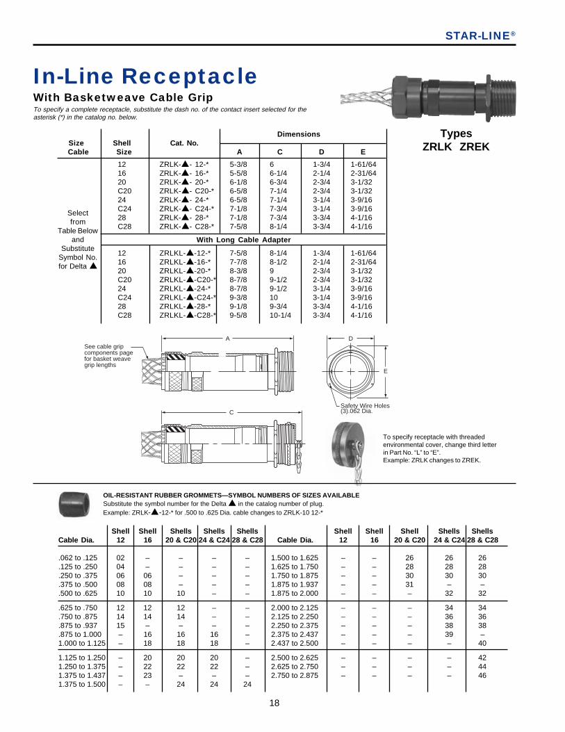
Safety Wire Holes(3).062 Dia.
D
E
ASee cable gripcomponents pagefor basket weave grip lengths
STAR-LINE®
TypesZRLK ZREK
Shell Shell Shells Shells Shells Shell Shell Shell Shells ShellsCable Dia. 12 16 20 & C20 24 & C24 28 & C28 Cable Dia. 12 16 20 & C20 24 & C24 28 & C28
.062 to .125 02 – – – – 1.500 to 1.625 – – 26 26 26
.125 to .250 04 – – – – 1.625 to 1.750 – – 28 28 28
.250 to .375 06 06 – – – 1.750 to 1.875 – – 30 30 30
.375 to .500 08 08 – – – 1.875 to 1.937 – – 31 – –
.500 to .625 10 10 10 – – 1.875 to 2.000 – – – 32 32
.625 to .750 12 12 12 – – 2.000 to 2.125 – – – 34 34
.750 to .875 14 14 14 – – 2.125 to 2.250 – – – 36 36
.875 to .937 15 – – – – 2.250 to 2.375 – – – 38 38
.875 to 1.000 – 16 16 16 – 2.375 to 2.437 – – – 39 –1.000 to 1.125 – 18 18 18 – 2.437 to 2.500 – – – – 40
1.125 to 1.250 – 20 20 20 – 2.500 to 2.625 – – – – 421.250 to 1.375 – 22 22 22 – 2.625 to 2.750 – – – – 441.375 to 1.437 – 23 – – – 2.750 to 2.875 – – – – 461.375 to 1.500 – – 24 24 24
In-Line ReceptacleWith Basketweave Cable GripTo specify a complete receptacle, substitute the dash no. of the contact insert selected for theasterisk (*) in the catalog no. below.
OIL-RESISTANT RUBBER GROMMETS—SYMBOL NUMBERS OF SIZES AVAILABLESubstitute the symbol number for the Delta ▲ in the catalog number of plug.Example: ZRLK-▲-12-* for .500 to .625 Dia. cable changes to ZRLK-10 12-*
DimensionsSize Shell Cat. No.Cable Size A C D E
12 ZRLK-▲- 12-* 5-3/8 6 1-3/4 1-61/6416 ZRLK-▲- 16-* 5-5/8 6-1/4 2-1/4 2-31/6420 ZRLK-▲- 20-* 6-1/8 6-3/4 2-3/4 3-1/32C20 ZRLK-▲- C20-* 6-5/8 7-1/4 2-3/4 3-1/3224 ZRLK-▲- 24-* 6-5/8 7-1/4 3-1/4 3-9/16C24 ZRLK-▲- C24-* 7-1/8 7-3/4 3-1/4 3-9/1628 ZRLK-▲- 28-* 7-1/8 7-3/4 3-3/4 4-1/16C28 ZRLK-▲- C28-* 7-5/8 8-1/4 3-3/4 4-1/16
12 ZRLKL-▲-12-* 7-5/8 8-1/4 1-3/4 1-61/6416 ZRLKL-▲-16-* 7-7/8 8-1/2 2-1/4 2-31/6420 ZRLKL-▲-20-* 8-3/8 9 2-3/4 3-1/32C20 ZRLKL-▲-C20-* 8-7/8 9-1/2 2-3/4 3-1/3224 ZRLKL-▲-24-* 8-7/8 9-1/2 3-1/4 3-9/16C24 ZRLKL-▲-C24-* 9-3/8 10 3-1/4 3-9/1628 ZRLKL-▲-28-* 9-1/8 9-3/4 3-3/4 4-1/16C28 ZRLKL-▲-C28-* 9-5/8 10-1/4 3-3/4 4-1/16
Selectfrom
Table Belowand
SubstituteSymbol No.for Delta ▲
With Long Cable Adapter
To specify receptacle with threadedenvironmental cover, change third letterin Part No. “L” to “E”.Example: ZRLK changes to ZREK.
C

19
AmphenolINDUSTRIAL
STAR-LINE®
Dimensions Shell Size Size Conduit Cat. No. A B C D E
12 3/4 ZRLT-2 12-* 4-1/4 3/4 4-7/8 1-3/8 1-61/6416 1-1/4 ZRLT-4 16-* 4-3/8 1-1/4 5 2-1/4 2-15/3220 1-1/2 ZRLT-5 20-* 4-1/2 1-1/2 5-1/8 2-3/4 3-1/32C20 1-1/2 ZRLT-5 C20-* 5 1-1/2 5-5/8 2-3/4 3-1/3224 2 ZRLT-6 24-* 4-5/8 2 5-1/4 3-1/4 3-9/16C24 2 ZRLT-6 C24 5-1/8 2 5-3/4 3-1/4 3-9/1628 2-1/2 ZRLT-7 28-* 5-3/32 2-1/2 5-23-32 3-3/4 4-1/16C28 2-1/2 ZRLT-7 C28-* 5-19/32 2-1/2 6-7/32 3-3/4 4-1/16
In-Line ReceptacleWith Conduit Adapter(for flexible conduit fittings)
To specify a complete receptacle, substitute the dash no. of thecontact insert selected, for the asterisk (*) in the catalog no. below.To specify receptacle with threaded environmental cover, change third letter in part no. “L” to “E””.
TypesZRLT ZRET
To specify receptacle with threadedenvironmental cover, change third letterin Part No. “L” to “E”.Example: ZRLT changes to ZRET.
A
BNPTThread
D
E
Safety Wire Holes(3) .062 Dia.
C
BNPTThread
20
G
5/8F
N Max panel thicknesswhen back mountedusing jack nutplugs.**
1/16" Gasket Fitsfront or backof flange.
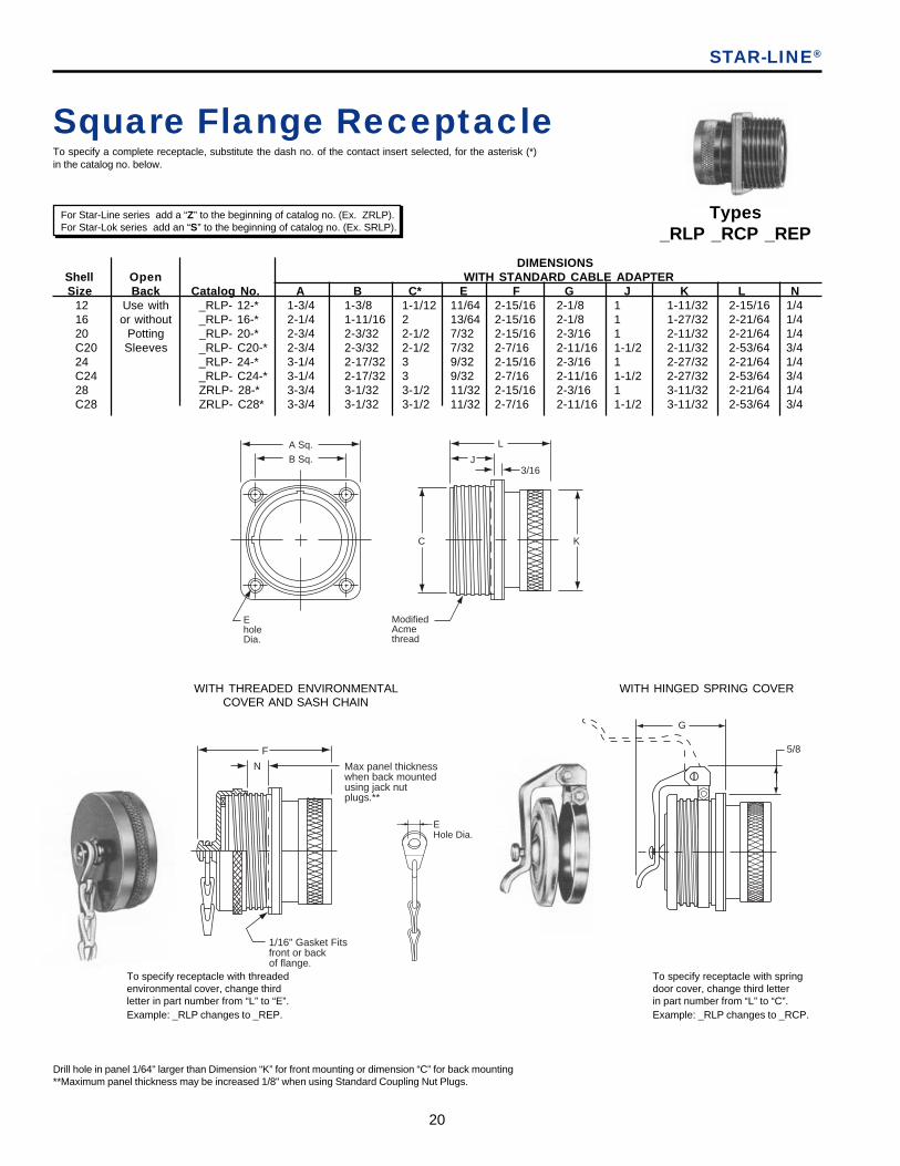
Square Flange ReceptacleTo specify a complete receptacle, substitute the dash no. of the contact insert selected, for the asterisk (*)in the catalog no. below.
STAR-LINE®
For Star-Line series add a “Z” to the beginning of catalog no. (Ex. ZRLP).For Star-Lok series add an “S” to the beginning of catalog no. (Ex. SRLP).
Types_RLP _RCP _REP
Drill hole in panel 1/64" larger than Dimension “K” for front mounting or dimension “C” for back mounting**Maximum panel thickness may be increased 1/8" when using Standard Coupling Nut Plugs.
EholeDia.
A Sq.
B Sq.
L
J3/16
C
ModifiedAcmethread
K
WITH THREADED ENVIRONMENTALCOVER AND SASH CHAIN
WITH HINGED SPRING COVER
To specify receptacle with springdoor cover, change third letterin part number from “L” to “C”.Example: _RLP changes to _RCP.
To specify receptacle with threadedenvironmental cover, change thirdletter in part number from “L” to “E”.Example: _RLP changes to _REP.
12 Use with _RLP- 12-* 1-3/4 1-3/8 1-1/12 11/64 2-15/16 2-1/8 1 1-11/32 2-15/16 1/416 or without _RLP- 16-* 2-1/4 1-11/16 2 13/64 2-15/16 2-1/8 1 1-27/32 2-21/64 1/420 Potting _RLP- 20-* 2-3/4 2-3/32 2-1/2 7/32 2-15/16 2-3/16 1 2-11/32 2-21/64 1/4C20 Sleeves _RLP- C20-* 2-3/4 2-3/32 2-1/2 7/32 2-7/16 2-11/16 1-1/2 2-11/32 2-53/64 3/424 _RLP- 24-* 3-1/4 2-17/32 3 9/32 2-15/16 2-3/16 1 2-27/32 2-21/64 1/4C24 _RLP- C24-* 3-1/4 2-17/32 3 9/32 2-7/16 2-11/16 1-1/2 2-27/32 2-53/64 3/428 ZRLP- 28-* 3-3/4 3-1/32 3-1/2 11/32 2-15/16 2-3/16 1 3-11/32 2-21/64 1/4C28 ZRLP- C28* 3-3/4 3-1/32 3-1/2 11/32 2-7/16 2-11/16 1-1/2 3-11/32 2-53/64 3/4
DIMENSIONSShell Open WITH STANDARD CABLE ADAPTERSize Back Catalog No. A B C* E F G J K L N
EHole Dia.
21
AmphenolINDUSTRIAL
A
G Max. Reversible clamps forcomplete cable range
F
E hole Dia.1/16" Gasket fitsfront or back of flange
B Sq.D Sq.
H
EHole Dia.
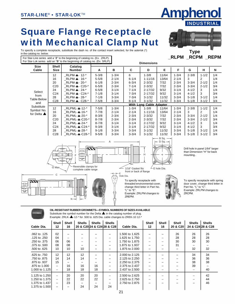
DimensionsSize Shell Catalog
Cable Size Number A B C D E F G H N
12 _RLPM-▲- 12-* 5-3/8 1-3/4 6 1-3/8 11/64 1-3/4 2-3/8 1-1/2 1/416 _RLPM-▲- 16-* 5-5/8 2-1/4 6-1/4 1-11/16 13/64 2-1/4 3 2 1/420 _RLPM-▲- 20-* 6-1/8 2-3/4 6-3/4 2-3/32 7/32 2-3/4 3-3/4 2-1/2 1/4C20 _RLPM-▲- C20-* 6-5/8 2-3/4 7-1/4 2-3/32 7/32 2-3/4 3-3/4 2-1/2 3/424 _RLPM-▲- 24-* 6-5/8 3-1/4 7-1/4 2-17/32 9/32 3-1/4 4-1/2 3 1/4C24 _RLPM-▲- C24-* 7-1/8 3-1/4 7-3/4 2-17/32 9/32 3-1/4 4-1/2 3 3/428 _RLPM-▲- 28-* 7-1/8 3-3/4 7-3/4 3-1/32 11/32 3-3/4 5-1/8 3-1/2 1/4C28 _RLPM-▲- C28-* 7-5/8 3-3/4 8-1/4 3-1/32 11/32 3-3/4 5-1/8 3-1/2 3/4
With Long Cable Adapter12 _RLPML-▲-12-* 7-5/8 1-3/4 1-3/4 1-3/8 11/64 1-3/4 2-3/8 1-1/2 1/416 _RLPML-▲-16-* 7-7/8 2-1/4 2-1/4 1-11/16 13/64 2-1/4 3 2 1/420 _RLPML-▲-20-* 8-3/8 2-3/4 2-3/4 2-3/32 7/32 2-3/4 3-3/4 2-1/2 1/4C20 _RLPML-▲-C20-* 8-7/8 2-3/4 2-3/4 2-3/32 7/32 2-3/4 3-3/4 2-1/2 3/424 _RLPML-▲-24-* 8-7/8 3-1/4 3-1/4 2-17/32 9/32 3-1/4 4-1/2 3 1/4C24 _RLPML-▲-C24-* 9-3/8 3-1/4 3-1/4 2-17/32 9/32 3-1/4 4-1/2 3 3/428 _RLPML-▲-28-* 9-1/8 3-3/4 3-3/4 3-1/32 11/32 3-3/4 5-1/8 3-1/2 1/4C28 _RLPML-▲-C28-* 9-5/8 3-3/4 3-3/4 3-1/32 11/32 3-3/4 5-1/8 3-1/2 3/4
STAR-LINE® • STAR-LOKTM
Type_RLPM _RCPM _REPM
Square Flange Receptaclewith Mechanical Clamp NutTo specify a complete receptacle, substitute the dash no. of the contact insert selected, for the asterisk (*)in the catalog no. below.
Selectfrom
Table Belowand
SubstituteSymbol No.for Delta ▲
C
N
To specify receptacle withthreaded environmental cover,change third letter in Part No.“L” to “E”.Example: ZRLPM changes toZREPM.
Shell Shell Shells Shells Shells Shell Shell Shell Shells ShellsCable Dia. 12 16 20 & C20 24 & C24 28 & C28 Cable Dia. 12 16 20 & C20 24 & C24 28 & C28
.062 to .125 02 – – – – 1.500 to 1.625 – – 26 26 26
.125 to .250 04 – – – – 1.625 to 1.750 – – 28 28 28
.250 to .375 06 06 – – – 1.750 to 1.875 – – 30 30 30
.375 to .500 08 08 – – – 1.875 to 1.937 – – 31 – –
.500 to .625 10 10 10 – – 1.875 to 2.000 – – – 32 32
.625 to .750 12 12 12 – – 2.000 to 2.125 – – – 34 34
.750 to .875 14 14 14 – – 2.125 to 2.250 – – – 36 36
.875 to .937 15 – – – – 2.250 to 2.375 – – – 38 38
.875 to 1.000 – 16 16 16 – 2.375 to 2.437 – – – 39 –1.000 to 1.125 – 18 18 18 – 2.437 to 2.500 – – – – 40
1.125 to 1.250 – 20 20 20 – 2.500 to 2.625 – – – – 421.250 to 1.375 – 22 22 22 – 2.625 to 2.750 – – – – 441.375 to 1.437 – 23 – – – 2.750 to 2.875 – – – – 461.375 to 1.500 – – 24 24 24
OIL-RESISTANT RUBBER GROMMETS—SYMBOL NUMBERS OF SIZES AVAILABLESubstitute the symbol number for the Delta ▲ in the catalog number of plug.Example: ZRLK-▲-12-* for .500 to .625 Dia. cable changes to ZREK-10 12-*
To specify receptacle with springdoor cover, change third letter inPart No. “L” to “C”.Example: ZRLPM changes toZRCPM.
For Star-Line series add a “Z” to the beginning of catalog no. (Ex. ZRLP).For Star-Lok series add an “S” to the beginning of catalog no. (Ex. SRLP).
Drill hole in panel 1/64” largerthan Dimension “H” for backmounting..
22
Shell Hub DimensionsSize Size† Cat. No. A B C D E F G H
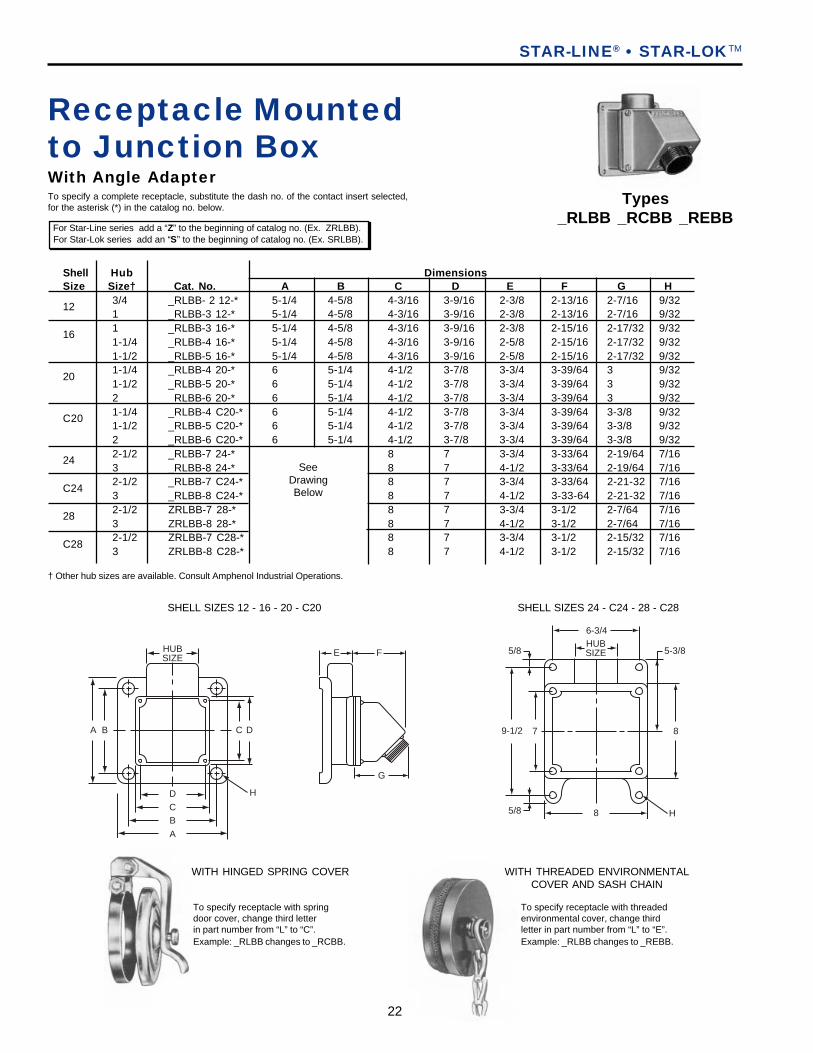
3/4 _RLBB- 2 12-* 5-1/4 4-5/8 4-3/16 3-9/16 2-3/8 2-13/16 2-7/16 9/321 _RLBB-3 12-* 5-1/4 4-5/8 4-3/16 3-9/16 2-3/8 2-13/16 2-7/16 9/321 _RLBB-3 16-* 5-1/4 4-5/8 4-3/16 3-9/16 2-3/8 2-15/16 2-17/32 9/321-1/4 _RLBB-4 16-* 5-1/4 4-5/8 4-3/16 3-9/16 2-5/8 2-15/16 2-17/32 9/321-1/2 _RLBB-5 16-* 5-1/4 4-5/8 4-3/16 3-9/16 2-5/8 2-15/16 2-17/32 9/321-1/4 _RLBB-4 20-* 6 5-1/4 4-1/2 3-7/8 3-3/4 3-39/64 3 9/321-1/2 _RLBB-5 20-* 6 5-1/4 4-1/2 3-7/8 3-3/4 3-39/64 3 9/322 _RLBB-6 20-* 6 5-1/4 4-1/2 3-7/8 3-3/4 3-39/64 3 9/321-1/4 _RLBB-4 C20-* 6 5-1/4 4-1/2 3-7/8 3-3/4 3-39/64 3-3/8 9/321-1/2 _RLBB-5 C20-* 6 5-1/4 4-1/2 3-7/8 3-3/4 3-39/64 3-3/8 9/322 _RLBB-6 C20-* 6 5-1/4 4-1/2 3-7/8 3-3/4 3-39/64 3-3/8 9/322-1/2 _RLBB-7 24-* 8 7 3-3/4 3-33/64 2-19/64 7/163 _RLBB-8 24-* 8 7 4-1/2 3-33/64 2-19/64 7/162-1/2 _RLBB-7 C24-* 8 7 3-3/4 3-33/64 2-21-32 7/163 _RLBB-8 C24-* 8 7 4-1/2 3-33-64 2-21-32 7/162-1/2 ZRLBB-7 28-* 8 7 3-3/4 3-1/2 2-7/64 7/163 ZRLBB-8 28-* 8 7 4-1/2 3-1/2 2-7/64 7/162-1/2 ZRLBB-7 C28-* 8 7 3-3/4 3-1/2 2-15/32 7/163 ZRLBB-8 C28-* 8 7 4-1/2 3-1/2 2-15/32 7/16
Receptacle Mountedto Junction BoxWith Angle Adapter
SeeDrawingBelow
12
16
20
C20
24
C24
28
C28
Types_RLBB _RCBB _REBB
For Star-Line series add a “Z” to the beginning of catalog no. (Ex. ZRLBB). For Star-Lok series add an “S” to the beginning of catalog no. (Ex. SRLBB).
STAR-LINE® • STAR-LOKTM
SHELL SIZES 12 - 16 - 20 - C20 SHELL SIZES 24 - C24 - 28 - C28
To specify a complete receptacle, substitute the dash no. of the contact insert selected,for the asterisk (*) in the catalog no. below.
HUBSIZE
D
CB
A
H
A C DB
E F
G
8 H
9-1/2
5/8
5/8
6-3/4HUBSIZE 5-3/8
87
To specify receptacle with springdoor cover, change third letterin part number from “L” to “C”.Example: _RLBB changes to _RCBB.
To specify receptacle with threadedenvironmental cover, change thirdletter in part number from “L” to “E”.Example: _RLBB changes to _REBB.
WITH THREADED ENVIRONMENTALCOVER AND SASH CHAIN
WITH HINGED SPRING COVER
† Other hub sizes are available. Consult Amphenol Industrial Operations.
23
AmphenolINDUSTRIAL
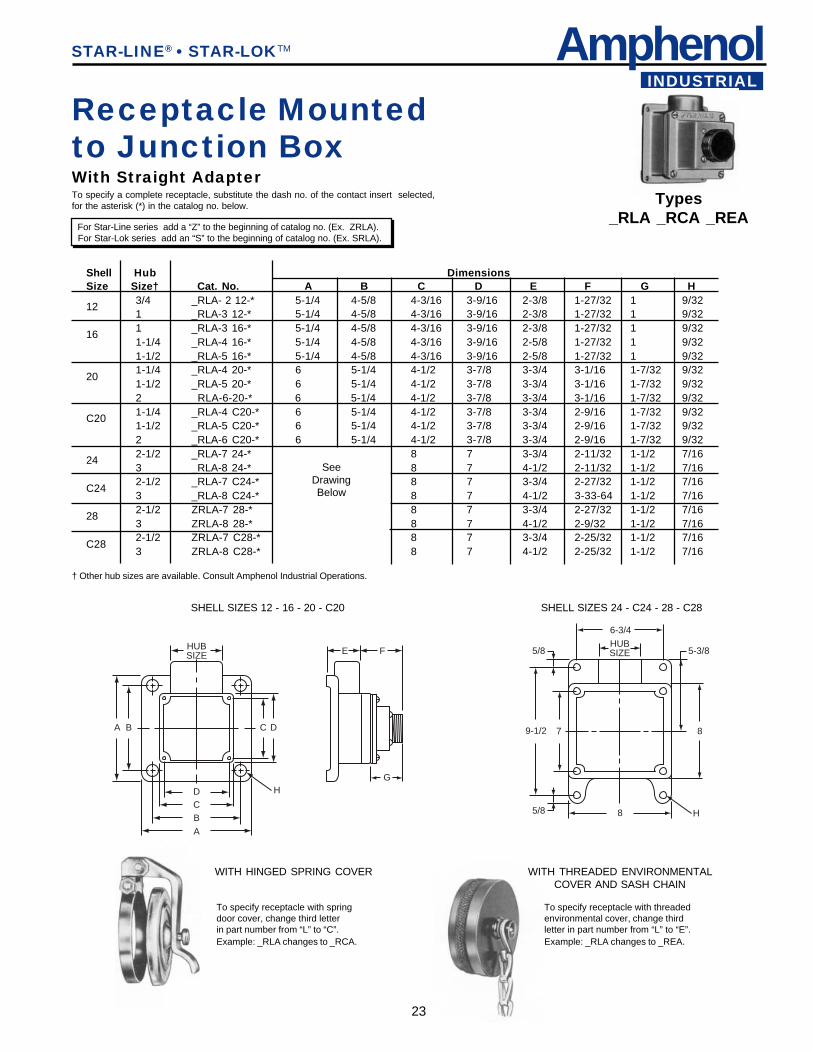
Receptacle Mountedto Junction BoxWith Straight AdapterTo specify a complete receptacle, substitute the dash no. of the contact insert selected,for the asterisk (*) in the catalog no. below. Types
_RLA _RCA _REA For Star-Line series add a “Z” to the beginning of catalog no. (Ex. ZRLA). For Star-Lok series add an “S” to the beginning of catalog no. (Ex. SRLA).
STAR-LINE® • STAR-LOKTM
Shell Hub DimensionsSize Size† Cat. No. A B C D E F G H
3/4 _RLA- 2 12-* 5-1/4 4-5/8 4-3/16 3-9/16 2-3/8 1-27/32 1 9/321 _RLA-3 12-* 5-1/4 4-5/8 4-3/16 3-9/16 2-3/8 1-27/32 1 9/321 _RLA-3 16-* 5-1/4 4-5/8 4-3/16 3-9/16 2-3/8 1-27/32 1 9/321-1/4 _RLA-4 16-* 5-1/4 4-5/8 4-3/16 3-9/16 2-5/8 1-27/32 1 9/321-1/2 _RLA-5 16-* 5-1/4 4-5/8 4-3/16 3-9/16 2-5/8 1-27/32 1 9/321-1/4 _RLA-4 20-* 6 5-1/4 4-1/2 3-7/8 3-3/4 3-1/16 1-7/32 9/321-1/2 _RLA-5 20-* 6 5-1/4 4-1/2 3-7/8 3-3/4 3-1/16 1-7/32 9/322 _RLA-6-20-* 6 5-1/4 4-1/2 3-7/8 3-3/4 3-1/16 1-7/32 9/321-1/4 _RLA-4 C20-* 6 5-1/4 4-1/2 3-7/8 3-3/4 2-9/16 1-7/32 9/321-1/2 _RLA-5 C20-* 6 5-1/4 4-1/2 3-7/8 3-3/4 2-9/16 1-7/32 9/322 _RLA-6 C20-* 6 5-1/4 4-1/2 3-7/8 3-3/4 2-9/16 1-7/32 9/322-1/2 _RLA-7 24-* 8 7 3-3/4 2-11/32 1-1/2 7/163 _RLA-8 24-* 8 7 4-1/2 2-11/32 1-1/2 7/162-1/2 _RLA-7 C24-* 8 7 3-3/4 2-27/32 1-1/2 7/163 _RLA-8 C24-* 8 7 4-1/2 3-33-64 1-1/2 7/162-1/2 ZRLA-7 28-* 8 7 3-3/4 2-27/32 1-1/2 7/163 ZRLA-8 28-* 8 7 4-1/2 2-9/32 1-1/2 7/162-1/2 ZRLA-7 C28-* 8 7 3-3/4 2-25/32 1-1/2 7/163 ZRLA-8 C28-* 8 7 4-1/2 2-25/32 1-1/2 7/16
SeeDrawingBelow
12
16
20
C20
24
C24
28
C28
SHELL SIZES 12 - 16 - 20 - C20 SHELL SIZES 24 - C24 - 28 - C28
To specify receptacle with springdoor cover, change third letterin part number from “L” to “C”.Example: _RLA changes to _RCA.
To specify receptacle with threadedenvironmental cover, change thirdletter in part number from “L” to “E”.Example: _RLA changes to _REA.
WITH THREADED ENVIRONMENTALCOVER AND SASH CHAIN
WITH HINGED SPRING COVER
HUBSIZE
DCB
A
H
A C DB
E F
G
8 H
9-1/2
5/8
5/8
6-3/4
HUBSIZE 5-3/8
87
† Other hub sizes are available. Consult Amphenol Industrial Operations.
24
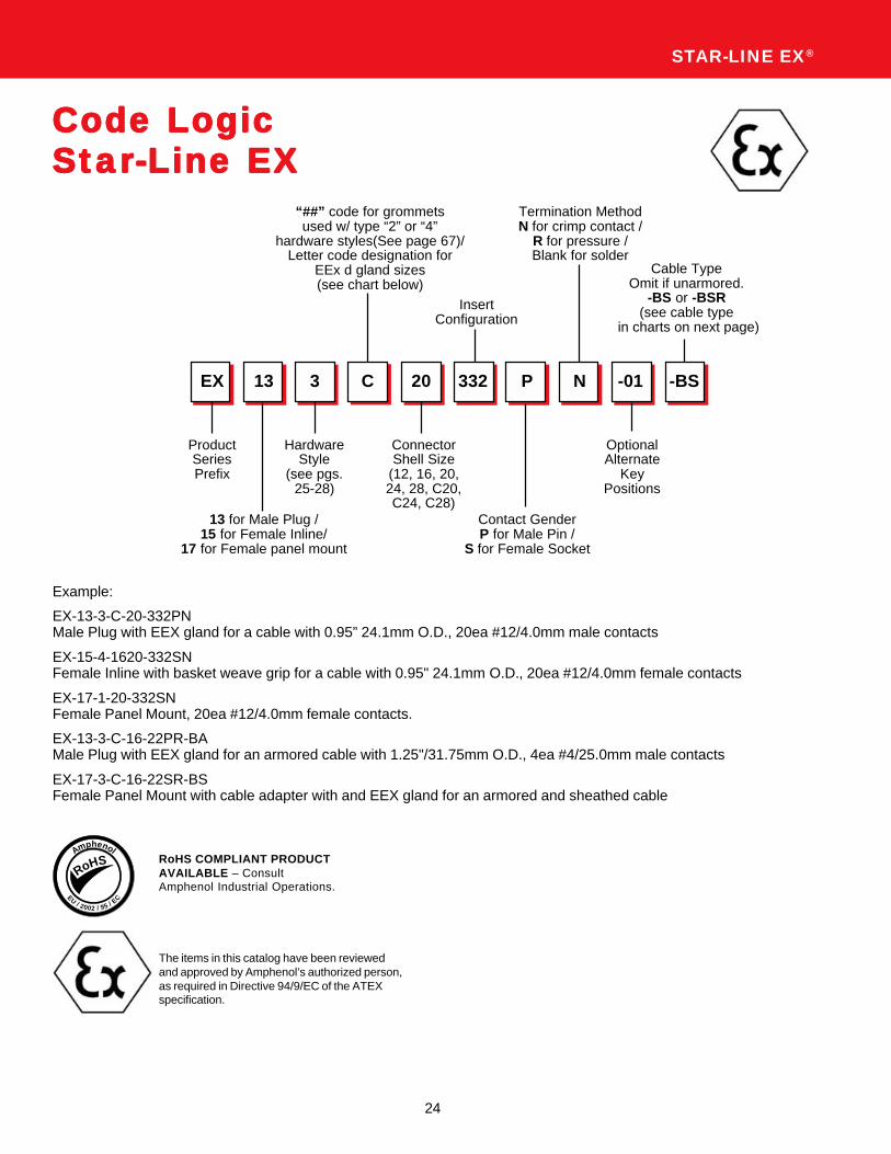
Code LogicCode LogicCode LogicCode LogicCode LogicStarStarStarStarStar-Line EX-Line EX-Line EX-Line EX-Line EX
EX 13 3
ProductSeriesPrefix
13 for Male Plug /15 for Female Inline/
17 for Female panel mount
“##” code for grommetsused w/ type “2” or “4”
hardware styles(See page 67)/Letter code designation for
EEx d gland sizes(see chart below)
Example:
EX-13-3-C-20-332PNMale Plug with EEX gland for a cable with 0.95” 24.1mm O.D., 20ea #12/4.0mm male contacts
EX-15-4-1620-332SNFemale Inline with basket weave grip for a cable with 0.95" 24.1mm O.D., 20ea #12/4.0mm female contacts
EX-17-1-20-332SNFemale Panel Mount, 20ea #12/4.0mm female contacts.
EX-13-3-C-16-22PR-BAMale Plug with EEX gland for an armored cable with 1.25"/31.75mm O.D., 4ea #4/25.0mm male contacts
EX-17-3-C-16-22SR-BSFemale Panel Mount with cable adapter with and EEX gland for an armored and sheathed cable
STAR-LINE EX®
C
ConnectorShell Size
(12, 16, 20,24, 28, C20,C24, C28)
20 332 P N -BS
InsertConfiguration
Contact GenderP for Male Pin /
S for Female Socket
OptionalAlternate
KeyPositions
Termination MethodN for crimp contact /
R for pressure /Blank for solder
Cable TypeOmit if unarmored.
-BS or -BSR(see cable type
in charts on next page)
-01
HardwareStyle
(see pgs.25-28)
RoHSAmphenol
EU/ 2002 / 95 / EC
RoHS COMPLIANT PRODUCTAVAILABLE – ConsultAmphenol Industrial Operations.
The items in this catalog have been reviewedand approved by Amphenol’s authorized person,as required in Directive 94/9/EC of the ATEXspecification.
25
AmphenolINDUSTRIAL
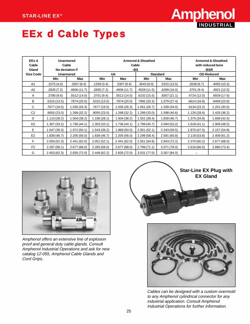
EEx d Unarmored Armored & Sheathed Armored & SheathedCable Cable Cable with reduced boreGland No deviation if -BS -BSR
Size Code Unarmored UA Standard OD-ReducedMin Max Min Max Min Max Min Max
A1 .1575 (4.0) .3307 (8.4) .1339 (3.4) .3307 (8.4) .3543 (9.0) .5315 (13.5) .2638 (6.7) .4055 (10.3)
A2 .2835 (7.2) .4606 (11.7) .2835 (7.2) .4606 (11.7) .4528 (11.5) .6299 (16.0) .3701 (9.4) .4921 (12.5)
A .3780 (9.6) .5512 (14.0) .3701 (9.4) .5512 (14.0) .6102 (15.5) .8307 (21.1) .4724 (12.0) .6929 (17.6)
B .5315 (13.5) .7874 (20.0) .5315 (13.5) .7874 (20.0) .7992 (20.3) 1.079 (27.4) .6614 (16.8) .9409 (23.9)
C .7677 (19.5) 1.035 (26.3) .7677 (19.5) 1.035 (26.3) 1.051 (26.7) 1.339 (34.0) .9134 (23.2) 1.201 (30.5)
C2 .9055 (23.0) 1.268 (32.2) .9055 (23.0) 1.268 (32.2) 1.299 (33.0) 1.598 (40.6) 1.126 (28.6) 1.425 (36.2)
D 1.110 (28.2) 1.504 (38.2) 1.106 (28.1) 1.504 (38.2) 1.551 (39.4) 1.839 (46.7) 1.370 (34.8) 1.669 (42.4)
D2 1.307 (33.2) 1.736 (44.1) 1.303 (33.1) 1.736 (44.1) 1.799 (45.7) 2.094 (53.2) 1.618 (41.1) 1.909 (48.5)
E 1.547 (39.3) 1.972 (50.1) 1.543 (39.2) 1.969 (50.0) 2.051 (52.1) 2.343 (59.5) 1.870 (47.5) 2.157 (54.8)
E2 1.839 (46.7) 2.205 (56.0) 1.839 (46.7) 2.205 (56.0) 2.299 (58.4) 2.591 (65.8) 2.118 (53.8) 2.409 (61.2)
F 2.059 (52.3) 2.441 (62.0) 2.051 (52.1) 2.441 (62.0) 2.551 (64.8) 2.843 (72.2) 2.370 (60.2) 2.677 (68.0)
F2 2.287 (58.1) 2.677 (68.0) 2.283 (58.0) 2.677 (68.0) 2.799 (71.1) 3.071 (78.0) 2.618 (66.5) 2.890 (73.4)
G 2.453 (62.3) 2.835 (72.0) 2.449 (62.2) 2.835 (72.0) 3.031 (77.0) 3.307 (84.0) –
AmphenolINDUSTRIAL
STAR-LINE EX®
EEx d Cable TEEx d Cable TEEx d Cable TEEx d Cable TEEx d Cable Typesypesypesypesypes
Star-Line EX Plug withEX Gland
Amphenol offers an extensive line of explosionproof and general duty cable glands. ConsultAmphenol Industrial Operations and ask for newcatalog 12-055, Amphenol Cable Glands andCord Grips.
Cables can be designed with a custom overmoldto any Amphenol cylindrical connector for anyindustrial application. Consult AmphenolIndustrial Operations for further information.
26
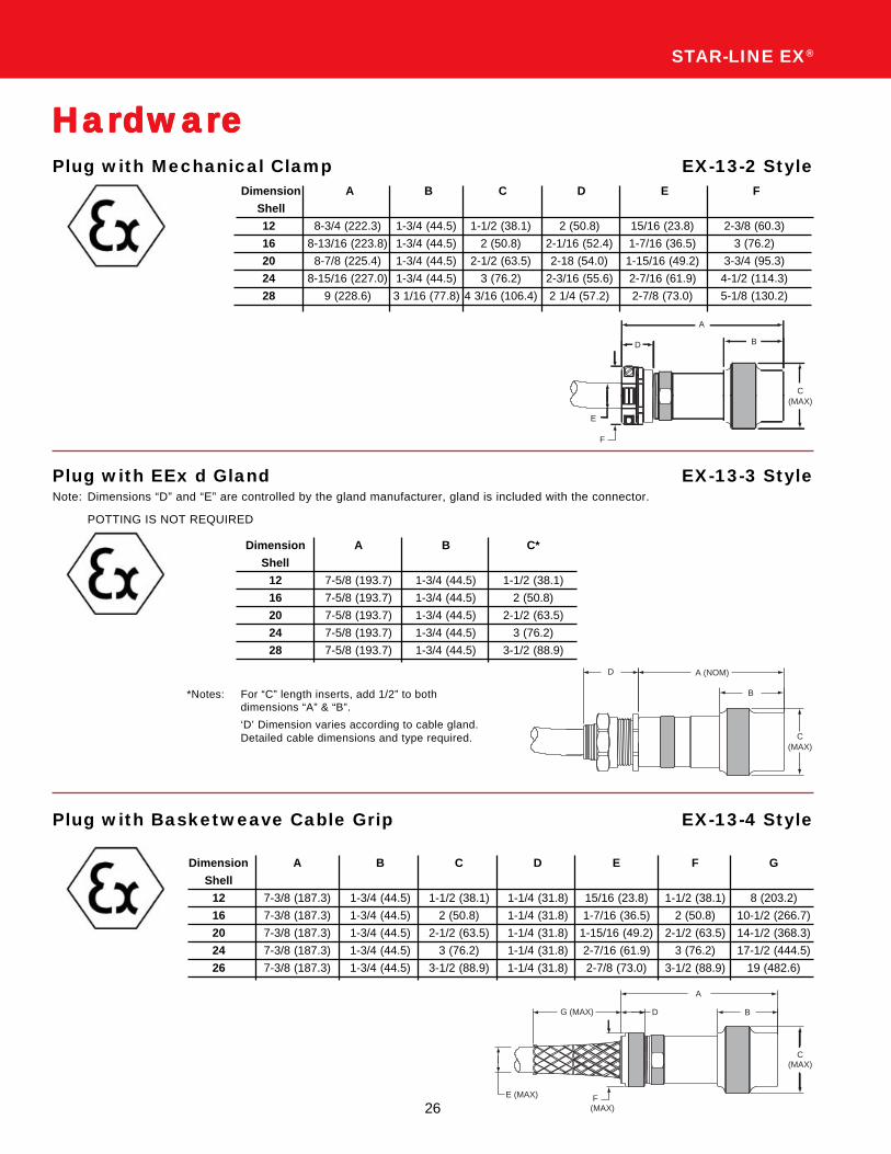
STAR-LINE EX®
Plug with Mechanical Clamp EX-13-2 Style
HHHHHararararardwardwardwardwardwareeeee
Dimension A B C D E F
Shell
12 8-3/4 (222.3) 1-3/4 (44.5) 1-1/2 (38.1) 2 (50.8) 15/16 (23.8) 2-3/8 (60.3)
16 8-13/16 (223.8) 1-3/4 (44.5) 2 (50.8) 2-1/16 (52.4) 1-7/16 (36.5) 3 (76.2)
20 8-7/8 (225.4) 1-3/4 (44.5) 2-1/2 (63.5) 2-18 (54.0) 1-15/16 (49.2) 3-3/4 (95.3)
24 8-15/16 (227.0) 1-3/4 (44.5) 3 (76.2) 2-3/16 (55.6) 2-7/16 (61.9) 4-1/2 (114.3)
28 9 (228.6) 3 1/16 (77.8) 4 3/16 (106.4) 2 1/4 (57.2) 2-7/8 (73.0) 5-1/8 (130.2)
Plug with EEx d Gland EX-13-3 StyleNote: Dimensions “D” and “E” are controlled by the gland manufacturer, gland is included with the connector.
POTTING IS NOT REQUIRED
Dimension A B C*
Shell
12 7-5/8 (193.7) 1-3/4 (44.5) 1-1/2 (38.1)
16 7-5/8 (193.7) 1-3/4 (44.5) 2 (50.8)
20 7-5/8 (193.7) 1-3/4 (44.5) 2-1/2 (63.5)
24 7-5/8 (193.7) 1-3/4 (44.5) 3 (76.2)
28 7-5/8 (193.7) 1-3/4 (44.5) 3-1/2 (88.9)
*Notes: For “C” length inserts, add 1/2” to bothdimensions “A” & “B”.
‘D’ Dimension varies according to cable gland.Detailed cable dimensions and type required.
Plug with Basketweave Cable Grip EX-13-4 Style
Dimension A B C D E F G
Shell
12 7-3/8 (187.3) 1-3/4 (44.5) 1-1/2 (38.1) 1-1/4 (31.8) 15/16 (23.8) 1-1/2 (38.1) 8 (203.2)
16 7-3/8 (187.3) 1-3/4 (44.5) 2 (50.8) 1-1/4 (31.8) 1-7/16 (36.5) 2 (50.8) 10-1/2 (266.7)
20 7-3/8 (187.3) 1-3/4 (44.5) 2-1/2 (63.5) 1-1/4 (31.8) 1-15/16 (49.2) 2-1/2 (63.5) 14-1/2 (368.3)
24 7-3/8 (187.3) 1-3/4 (44.5) 3 (76.2) 1-1/4 (31.8) 2-7/16 (61.9) 3 (76.2) 17-1/2 (444.5)
26 7-3/8 (187.3) 1-3/4 (44.5) 3-1/2 (88.9) 1-1/4 (31.8) 2-7/8 (73.0) 3-1/2 (88.9) 19 (482.6)
D B
C(MAX)
A
E
F
G (MAX) D
A
B
C(MAX)
F(MAX)
E (MAX)
A (NOM)
B
C(MAX)
D

27
AmphenolINDUSTRIAL
AmphenolIn-line Receptacle with Mechanical Clamp EX-15-2 Style
In-line Receptacle with EEx d Gland EX-15-3 StylePOTTING IS NOT REQUIRED
In-line Receptacle with Basketweave Cable Grip EX-15-4 Style
Dimension A B C D E F
Shell
12 8-3/4 (222.3) 1-3/4 (44.5) 1-1/2 (38.1) 2 (50.8) 15/16 (23.8) 2-3/8 (60.3)
16 8-13/16 (223.8) 1-3/4 (44.5) 2 (50.8) 2-1/16 (52.4) 1-7/16 (36.5) 3 (76.2)
20 8-7/8 (225.4) 1-3/4 (44.5) 2-1/2 (63.5) 2-1/8 (54.0) 1-15/16 (49.2) 3-3/4 (95.3)
24 8-15/16 (227.0) 1-3/4 (44.5) 3 (76.2) 2-3/16 (55.6) 2-7/16 (61.9) 4-1/2 (114.3)
28 9 (228.6) 1-3/4 (44.5) 3-1/2 (88.9) 2-1/4 (57.2) 2-7/8 (73.0) 5-1/8 (130.2)
Dimension A B C*
Shell
12 7-5/8 (193.7) 1-3/4 (44.5) 1-1/2 (38.1)
16 7-5/8 (193.7) 1-3/4 (44.5) 2 (50.8)
20 7-5/8 (193.7) 1-3/4 (44.5) 2-1/2 (63.5)
24 7-5/8 (193.7) 1-3/4 (44.5) 3 (76.2)
28 7-5/8 (193.7) 1-3/4 (44.5) 3-1/2 (88.9)
*Notes: For “C” length inserts, add 1/2” to bothdimensions “A” & “B”.‘D’ Dimension varies according to cable gland.Detailed cable dimension and type required.
Dimension A B C D E F G
Shell
12 7-3/8 (187.3) 1-3/4 (44.5) 1-1/2 (38.1) 1-1/4 (31.8) 15/16 (23.8) 1-1/2 (38.1) 8 (203.2)
16 7-3/8 (187.3) 1-3/4 (44.5) 2 (50.8) 1-1/4 (31.8) 1-7/16 (36.5) 2 (50.8) 10-1/2 (266.7)
20 7-3/8 (187.3) 1-3/4 (44.5) 2-1/2 (63.5) 1-1/4 (31.8) 1-15/16 (49.2) 2-1/2 (63.5) 14-1/2 (368.3)
24 7-3/8 (187.3) 1-3/4 (44.5) 3 (76.2) 1-1/4 (31.8) 2-7/16 (61.9) 3 (76.2) 17-1/2 (444.5)
28 7-3/8 (187.3) 1-3/4 (44.5) 3-1/2 (88.9) 1-1/4 (31.8) 2-7/8 (73.0) 3-1/2 (88.9) 19 (482.6)
A
B
CE
D F (MAX)
C
B
A
DF (MAX)
G(MAX)
E
C
D
A
B
INDUSTRIAL
28
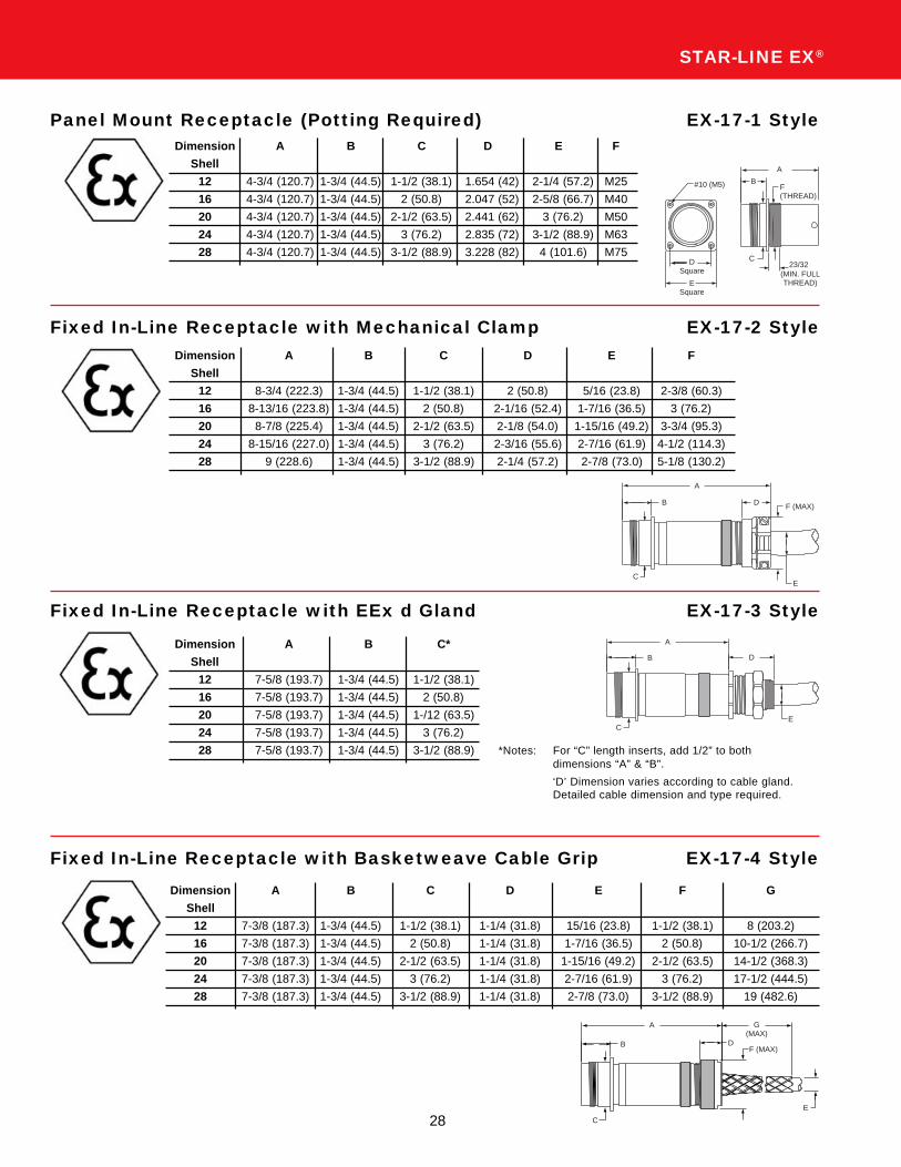
STAR-LINE EX®
Panel Mount Receptacle (Potting Required) EX-17-1 StyleDimension A B C D E F
Shell
12 4-3/4 (120.7) 1-3/4 (44.5) 1-1/2 (38.1) 1.654 (42) 2-1/4 (57.2) M25
16 4-3/4 (120.7) 1-3/4 (44.5) 2 (50.8) 2.047 (52) 2-5/8 (66.7) M40
20 4-3/4 (120.7) 1-3/4 (44.5) 2-1/2 (63.5) 2.441 (62) 3 (76.2) M50
24 4-3/4 (120.7) 1-3/4 (44.5) 3 (76.2) 2.835 (72) 3-1/2 (88.9) M63
28 4-3/4 (120.7) 1-3/4 (44.5) 3-1/2 (88.9) 3.228 (82) 4 (101.6) M75
Fixed In-Line Receptacle with Mechanical Clamp EX-17-2 StyleDimension A B C D E F
Shell
12 8-3/4 (222.3) 1-3/4 (44.5) 1-1/2 (38.1) 2 (50.8) 5/16 (23.8) 2-3/8 (60.3)
16 8-13/16 (223.8) 1-3/4 (44.5) 2 (50.8) 2-1/16 (52.4) 1-7/16 (36.5) 3 (76.2)
20 8-7/8 (225.4) 1-3/4 (44.5) 2-1/2 (63.5) 2-1/8 (54.0) 1-15/16 (49.2) 3-3/4 (95.3)
24 8-15/16 (227.0) 1-3/4 (44.5) 3 (76.2) 2-3/16 (55.6) 2-7/16 (61.9) 4-1/2 (114.3)
28 9 (228.6) 1-3/4 (44.5) 3-1/2 (88.9) 2-1/4 (57.2) 2-7/8 (73.0) 5-1/8 (130.2)
Fixed In-Line Receptacle with EEx d Gland EX-17-3 Style
*Notes: For “C” length inserts, add 1/2” to bothdimensions “A” & “B”.
‘D’ Dimension varies according to cable gland.Detailed cable dimension and type required.
Dimension A B C*
Shell
12 7-5/8 (193.7) 1-3/4 (44.5) 1-1/2 (38.1)
16 7-5/8 (193.7) 1-3/4 (44.5) 2 (50.8)
20 7-5/8 (193.7) 1-3/4 (44.5) 1-/12 (63.5)
24 7-5/8 (193.7) 1-3/4 (44.5) 3 (76.2)
28 7-5/8 (193.7) 1-3/4 (44.5) 3-1/2 (88.9)
Fixed In-Line Receptacle with Basketweave Cable Grip EX-17-4 Style
Dimension A B C D E F G
Shell
12 7-3/8 (187.3) 1-3/4 (44.5) 1-1/2 (38.1) 1-1/4 (31.8) 15/16 (23.8) 1-1/2 (38.1) 8 (203.2)
16 7-3/8 (187.3) 1-3/4 (44.5) 2 (50.8) 1-1/4 (31.8) 1-7/16 (36.5) 2 (50.8) 10-1/2 (266.7)
20 7-3/8 (187.3) 1-3/4 (44.5) 2-1/2 (63.5) 1-1/4 (31.8) 1-15/16 (49.2) 2-1/2 (63.5) 14-1/2 (368.3)
24 7-3/8 (187.3) 1-3/4 (44.5) 3 (76.2) 1-1/4 (31.8) 2-7/16 (61.9) 3 (76.2) 17-1/2 (444.5)
28 7-3/8 (187.3) 1-3/4 (44.5) 3-1/2 (88.9) 1-1/4 (31.8) 2-7/8 (73.0) 3-1/2 (88.9) 19 (482.6)
A
B
CE
D F (MAX)
C
D
E
A
B
C
B
A
DF (MAX)
G(MAX)
E
#10 (M5)
A
BF(THREAD)
C
ESquare
DSquare
23/32(MIN. FULLTHREAD)
29
AmphenolINDUSTRIAL
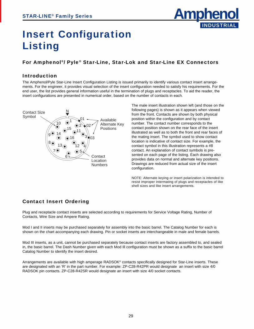
Insert ConfigurationListingFor Amphenol®/ Pyle® Star-Line, Star-Lok and Star-Line EX Connectors
IntroductionThe Amphenol/Pyle Star-Line Insert Configuration Listing is issued primarily to identify various contact insert arrange-ments. For the engineer, it provides visual selection of the insert configuration needed to satisfy his requirements. For theend user, the list provides general information useful in the termination of plugs and receptacles. To aid the reader, theinsert configurations are presented in numerical order, based on the number of contacts in each.
The male insert illustration shown left (and those on thefollowing pages) is shown as it appears when viewedfrom the front. Contacts are shown by both physicalposition within the configuration and by contactnumber. The contact number corresponds to thecontact position shown on the rear face of the insertillustrated as well as to both the front and rear faces ofthe mating insert. The symbol used to show contactlocation is indicative of contact size. For example, thecontact symbol in this illustration represents a #8contact. An explanation of contact symbols is pre-sented on each page of the listing. Each drawing alsoprovides data on normal and alternate key positions.Drawings are reduced from actual size of the insertconfiguration.
NOTE: Alternate keying or insert polarization is intended toresist improper intermating of plugs and receptacles of likeshell sizes and like insert arrangements.
Contact Insert Ordering
Plug and receptacle contact inserts are selected according to requirements for Service Voltage Rating, Number ofContacts, Wire Size and Ampere Rating.
Mod I and II inserts may be purchased separately for assembly into the basic barrel. The Catalog Number for each isshown on the chart accompanying each drawing. Pin or socket inserts are interchangeable in male and female barrels.
Mod III inserts, as a unit, cannot be purchased separately because contact inserts are factory assembled to, and sealedin, the basic barrel. The Dash Number given with each Mod Ill configuration must be shown as a suffix to the basic barrelCatalog Number to identify the insert desired.
Arrangements are available with high amperage RADSOK® contacts specifically designed for Star-Line inserts. Theseare designated with an ‘R’ in the part number. For example: ZP-C28-R42PR would designate an insert with size 4/0RADSOK pin contacts. ZP-C28-R42SR would designate an insert with size 4/0 socket contacts.
STAR-LINE® Family Series
N
12
3
45
6
7
8
9
10
11
1213
1415
16
01
02
03
Contact SizeSymbol
AvailableAlternate KeyPositions
ContactLocationNumbers
30
STAR-LINE® Family Series
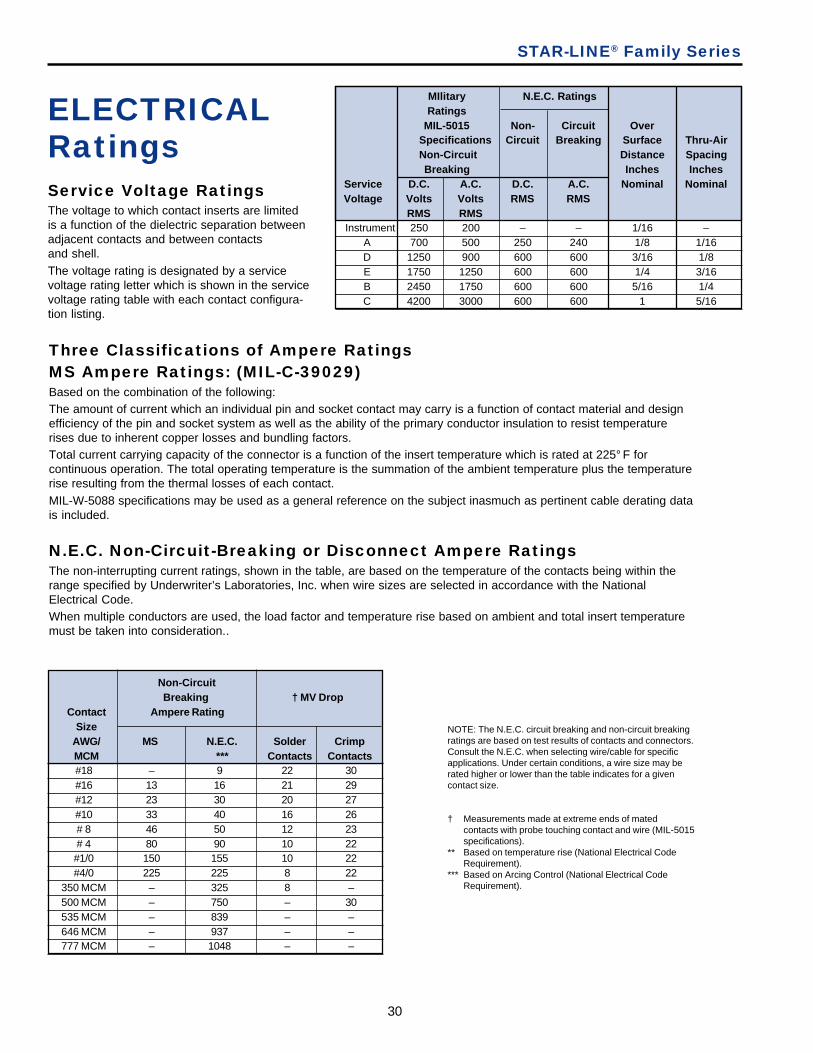
Three Classifications of Ampere RatingsMS Ampere Ratings: (MIL-C-39029)Based on the combination of the following:The amount of current which an individual pin and socket contact may carry is a function of contact material and designefficiency of the pin and socket system as well as the ability of the primary conductor insulation to resist temperaturerises due to inherent copper losses and bundling factors.Total current carrying capacity of the connector is a function of the insert temperature which is rated at 225° F forcontinuous operation. The total operating temperature is the summation of the ambient temperature plus the temperaturerise resulting from the thermal losses of each contact.MIL-W-5088 specifications may be used as a general reference on the subject inasmuch as pertinent cable derating datais included.
N.E.C. Non-Circuit-Breaking or Disconnect Ampere RatingsThe non-interrupting current ratings, shown in the table, are based on the temperature of the contacts being within therange specified by Underwriter’s Laboratories, Inc. when wire sizes are selected in accordance with the NationalElectrical Code.When multiple conductors are used, the load factor and temperature rise based on ambient and total insert temperaturemust be taken into consideration..
Service Voltage RatingsThe voltage to which contact inserts are limitedis a function of the dielectric separation betweenadjacent contacts and between contactsand shell.The voltage rating is designated by a servicevoltage rating letter which is shown in the servicevoltage rating table with each contact configura-tion listing.
ELECTRICALRatings
NOTE: The N.E.C. circuit breaking and non-circuit breakingratings are based on test results of contacts and connectors.Consult the N.E.C. when selecting wire/cable for specificapplications. Under certain conditions, a wire size may berated higher or lower than the table indicates for a givencontact size.
† Measurements made at extreme ends of matedcontacts with probe touching contact and wire (MIL-5015specifications).
** Based on temperature rise (National Electrical CodeRequirement).
*** Based on Arcing Control (National Electrical CodeRequirement).
MIlitary N.E.C. RatingsRatings
MIL-5015 Non- Circuit OverSpecifications Circuit Breaking Surface Thru-AirNon-Circuit Distance SpacingBreaking Inches Inches
Service D.C. A.C. D.C. A.C. Nominal NominalVoltage Volts Volts RMS RMS
RMS RMS Instrument 250 200 – – 1/16 –
A 700 500 250 240 1/8 1/16D 1250 900 600 600 3/16 1/8E 1750 1250 600 600 1/4 3/16B 2450 1750 600 600 5/16 1/4C 4200 3000 600 600 1 5/16
Non-Circuit Breaking † MV Drop
Contact Ampere RatingSize
AWG/ MS N.E.C. Solder CrimpMCM *** Contacts Contacts#18 – 9 22 30#16 13 16 21 29#12 23 30 20 27#10 33 40 16 26# 8 46 50 12 23# 4 80 90 10 22#1/0 150 155 10 22#4/0 225 225 8 22
350 MCM – 325 8 –500 MCM – 750 – 30535 MCM – 839 – –646 MCM – 937 – –777 MCM – 1048 – –

31
AmphenolINDUSTRIAL
STAR-LINE® Family Series
Spare/Replacement Contacts forMOD II and MOD III InsertsContacts are machined copper alloy ranging in size (AWG) from #18 to 500 MCM.Standard line contacts are silver plated but can also be furnished with gold over silver, gold over nickel, and othercombinations of plating systems available upon request.Pin contacts are of blended geometry to provide extra strength and protection against damage. Socket contacts are theclosed entry type.Contacts for MOD I inserts are not listed because these inserts are factory assembled and damage may be done to theresilient center insulation if contacts are inserted or removed by inexperienced personnel in the field.
18 Pin ZP-4018-36L18 Socket ZP-4118-36L
16 Pin ZP-4016-36L ZP-4016-37L16 Socket ZP-4116-36L
12 Pin ZP-4012-36L ZP-4012-37L312 Socket ZP-4112-36L
10 Pin ZP-4010-36L ZP-4010-37L210 Socket ZP-4110-36L
8 Pin ZP-4008-66L8 Socket ZP-4108-66L
4 Pin ZP-4004-66L ZP-4804-66L4 Socket ZP-4104-66L ZP-4904-66L
1/0 Pin ZP-4000-66LB ZP-4800-66LKB1/0 Socket ZP-4100-66L ZP-4900-66LK
4/0 Pin ZP-4041-76LB4/0 Socket ZP-4141-76L
500 MCM Pin P-206053-CP500 MCM Socket P-206053-CS
535 MCM Pin RIG-C24-535PN535 MCM Socket RIG-C24-535SN
646-777 MCM Pin RIG-C24-386PN646-777 MCM Socket RIG-C24-386SN
MOD IIISize “W” “C” “W” Polarizing Polarizing
Awg/MCM Length Length Ground Standard “C”
18 Pin ZP-4018-50L18 Socket ZP-4118-50L
16 Pin ZP-4016-50L16 Socket ZP-4116-50L
12 Pin ZP-4012-50L ZP-4012-50LB ZP-4012-52LK12 Socket ZP-4112-50L
10 Pin ZP-4010-50L ZP-4010-52LK10 Socket ZP-4110-50L
8 Pin ZP-4008-50L ZP-4008-50LB8 Socket ZP-4108-50L
4 Pin ZP-4004-50L ZP-4004-52LK ZP-4804-50LK4 Socket ZP-4104-50L ZP-4904-50LK
1/0 Pin ZP-4100-50L ZP-4000-50LB ZP-4800-52LKB ZP-4800-50LK ZP-4800-50LKB1/0 Socket ZP-4100-50L ZP-4900-50LK
“W” length represents standard insert lenght for sizes 12, 16, 20 24 and 28. “C” length represents longer insert length forsizes C20, C24 and C28. Contacts in “C” length inserts are 1/2” longer than standard. Ground contacts are 1/8” longerthan standard. Ground clips are part of inserts. “C’ length ground contacts are 1/8” longer than “C” length line contacts.
Note: For RADSOK contact availability consult Amphenol Industrial Operations.
MOD IISize “W” “C” “W” Polarizing Polarizing
Awg/MCM Length Length Ground Standard “C”
32
Contact WIRE WELL DIMENSIONSSize Solder Mod I Crimp* Mod II Crimp* Mod III
AWG (mm) Diameter Depth Diameter Depth Diameter Depth
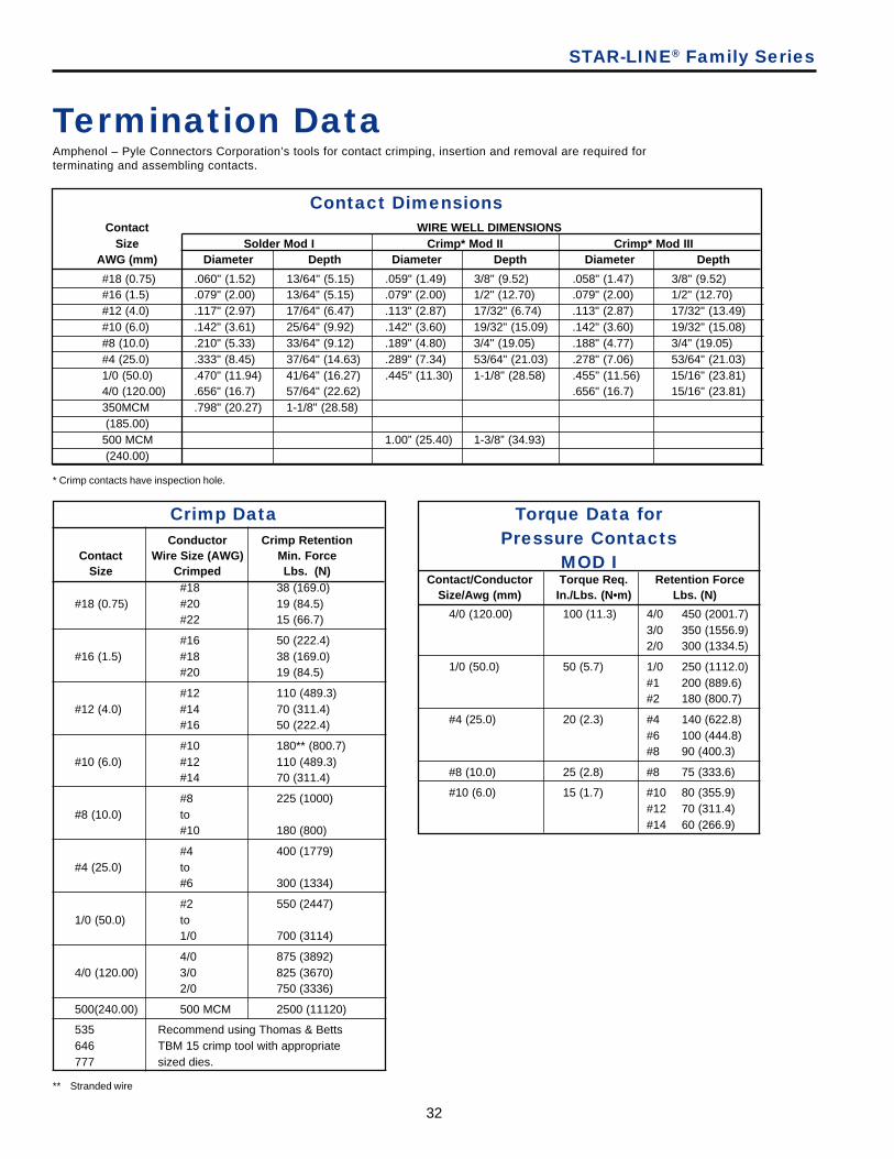
#18 (0.75) .060" (1.52) 13/64" (5.15) .059" (1.49) 3/8" (9.52) .058" (1.47) 3/8" (9.52)#16 (1.5) .079" (2.00) 13/64" (5.15) .079" (2.00) 1/2" (12.70) .079" (2.00) 1/2" (12.70)#12 (4.0) .117" (2.97) 17/64" (6.47) .113" (2.87) 17/32" (6.74) .113" (2.87) 17/32" (13.49)#10 (6.0) .142" (3.61) 25/64" (9.92) .142" (3.60) 19/32" (15.09) .142" (3.60) 19/32" (15.08)#8 (10.0) .210" (5.33) 33/64" (9.12) .189" (4.80) 3/4" (19.05) .188" (4.77) 3/4" (19.05)#4 (25.0) .333" (8.45) 37/64" (14.63) .289" (7.34) 53/64" (21.03) .278" (7.06) 53/64" (21.03)1/0 (50.0) .470" (11.94) 41/64" (16.27) .445" (11.30) 1-1/8" (28.58) .455" (11.56) 15/16" (23.81)4/0 (120.00) .656" (16.7) 57/64" (22.62) .656" (16.7) 15/16" (23.81)350MCM .798" (20.27) 1-1/8" (28.58) (185.00)500 MCM 1.00” (25.40) 1-3/8” (34.93) (240.00)
Termination DataAmphenol – Pyle Connectors Corporation’s tools for contact crimping, insertion and removal are required forterminating and assembling contacts.
Contact Dimensions
Torque Data forPressure Contacts
MOD I
STAR-LINE® Family Series
Contact/Conductor Torque Req. Retention ForceSize/Awg (mm) In./Lbs. (N•m) Lbs. (N)
4/0 (120.00) 100 (11.3) 4/0 450 (2001.7)3/0 350 (1556.9)2/0 300 (1334.5)
1/0 (50.0) 50 (5.7) 1/0 250 (1112.0)#1 200 (889.6)#2 180 (800.7)
#4 (25.0) 20 (2.3) #4 140 (622.8)#6 100 (444.8)#8 90 (400.3)
#8 (10.0) 25 (2.8) #8 75 (333.6)
#10 (6.0) 15 (1.7) #10 80 (355.9)#12 70 (311.4)#14 60 (266.9)
* Crimp contacts have inspection hole.
Crimp DataConductor Crimp Retention
Contact Wire Size (AWG) Min. ForceSize Crimped Lbs. (N)
#18 38 (169.0)#18 (0.75) #20 19 (84.5)
#22 15 (66.7)
#16 50 (222.4)#16 (1.5) #18 38 (169.0)
#20 19 (84.5)
#12 110 (489.3)#12 (4.0) #14 70 (311.4)
#16 50 (222.4)
#10 180** (800.7)#10 (6.0) #12 110 (489.3)
#14 70 (311.4)
#8 225 (1000)#8 (10.0) to
#10 180 (800)
#4 400 (1779)#4 (25.0) to
#6 300 (1334)
#2 550 (2447)1/0 (50.0) to
1/0 700 (3114)
4/0 875 (3892)4/0 (120.00) 3/0 825 (3670)
2/0 750 (3336)
500(240.00) 500 MCM 2500 (11120)
535 Recommend using Thomas & Betts646 TBM 15 crimp tool with appropriate777 sized dies.
** Stranded wire
33
AmphenolINDUSTRIAL
STAR-LINE® Family Series
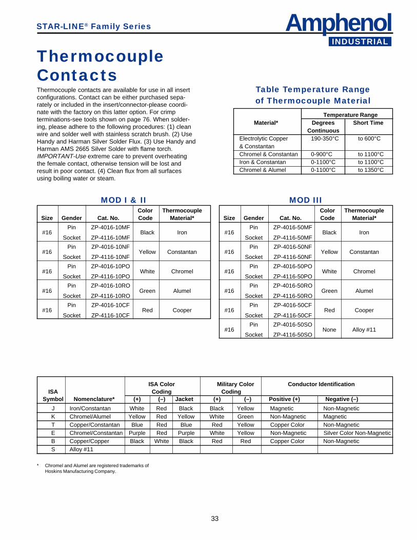
ThermocoupleContactsThermocouple contacts are available for use in all insertconfigurations. Contact can be either purchased sepa-rately or included in the insert/connector-please coordi-nate with the factory on this latter option. For crimpterminations-see tools shown on page 76. When solder-ing, please adhere to the following procedures: (1) cleanwire and solder well with stainless scratch brush. (2) UseHandy and Harman Silver Solder Flux. (3) Use Handy andHarman AMS 2665 Silver Solder with flame torch.IMPORTANT-Use extreme care to prevent overheatingthe female contact, otherwise tension will be lost andresult in poor contact. (4) Clean flux from all surfacesusing boiling water or steam.
Table Temperature Rangeof Thermocouple Material
Temperature RangeMaterial* Degrees Short Time
ContinuousElectrolytic Copper 190-350°C to 600°C& ConstantanChromel & Constantan 0-900°C to 1100°CIron & Constantan 0-1100°C to 1100°CChromel & Alumel 0-1100°C to 1350°C
MOD I & IIColor Thermocouple
Size Gender Cat. No. Code Material*
Pin ZP-4016-10MF#16 Black Iron
Socket ZP-4116-10MF
Pin ZP-4016-10NF#16 Yellow Constantan
Socket ZP-4116-10NF
Pin ZP-4016-10PO#16 White Chromel
Socket ZP-4116-10PO
Pin ZP-4016-10RO#16 Green Alumel
Socket ZP-4116-10RO
Pin ZP-4016-10CF#16 Red Cooper
Socket ZP-4116-10CF
MOD IIIColor Thermocouple
Size Gender Cat. No. Code Material*
Pin ZP-4016-50MF#16 Black Iron
Socket ZP-4116-50MF
Pin ZP-4016-50NF#16 Yellow Constantan
Socket ZP-4116-50NF
Pin ZP-4016-50PO#16 White Chromel
Socket ZP-4116-50PO
Pin ZP-4016-50RO#16 Green Alumel
Socket ZP-4116-50RO
Pin ZP-4016-50CF#16 Red Cooper
Socket ZP-4116-50CF
Pin ZP-4016-50SO#16 None Alloy #11
Socket ZP-4116-50SO
ISA Color Military Color Conductor IdentificationISA Coding Coding
Symbol Nomenclature* (+) (–) Jacket (+) (–) Positive (+) Negative (–)
J Iron/Constantan White Red Black Black Yellow Magnetic Non-MagneticK Chromel/Alumel Yellow Red Yellow White Green Non-Magnetic MagneticT Copper/Constantan Blue Red Blue Red Yellow Copper Color Non-MagneticE Chromel/Constantan Purple Red Purple White Yellow Non-Magnetic Silver Color Non-MagneticB Copper/Copper Black White Black Red Red Copper Color Non-MagneticS Alloy #11
* Chromel and Alumel are registered trademarks ofHoskins Manufacturing Company.
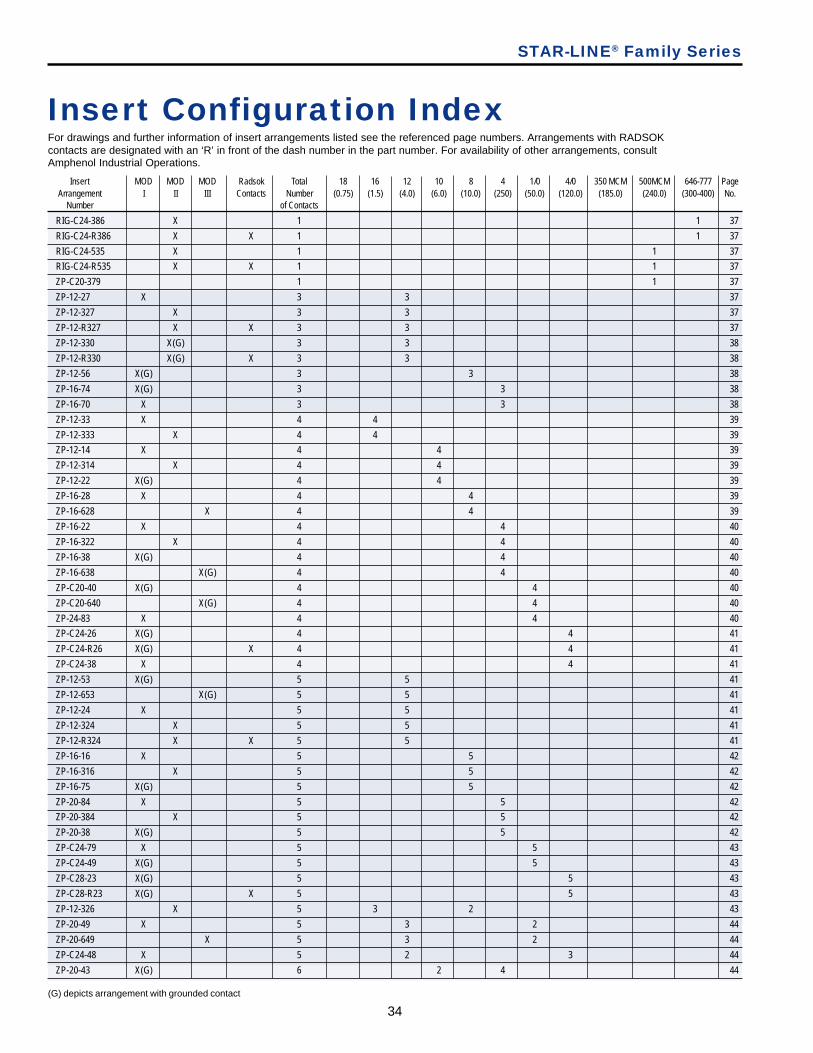
34
STAR-LINE® Family Series
Insert MOD MOD MOD Radsok Total 18 16 12 10 8 4 1/0 4/0 350 MCM 500MCM 646-777 PageArrangement I II III Contacts Number (0.75) (1.5) (4.0) (6.0) (10.0) (250) (50.0) (120.0) (185.0) (240.0) (300-400) No.
Number of Contacts
RIG-C24-386 X 1 1 37
RIG-C24-R386 X X 1 1 37
RIG-C24-535 X 1 1 37
RIG-C24-R535 X X 1 1 37
ZP-C20-379 1 1 37
ZP-12-27 X 3 3 37
ZP-12-327 X 3 3 37
ZP-12-R327 X X 3 3 37
ZP-12-330 X(G) 3 3 38
ZP-12-R330 X(G) X 3 3 38
ZP-12-56 X(G) 3 3 38
ZP-16-74 X(G) 3 3 38
ZP-16-70 X 3 3 38
ZP-12-33 X 4 4 39
ZP-12-333 X 4 4 39
ZP-12-14 X 4 4 39
ZP-12-314 X 4 4 39
ZP-12-22 X(G) 4 4 39
ZP-16-28 X 4 4 39
ZP-16-628 X 4 4 39
ZP-16-22 X 4 4 40
ZP-16-322 X 4 4 40
ZP-16-38 X(G) 4 4 40
ZP-16-638 X(G) 4 4 40
ZP-C20-40 X(G) 4 4 40
ZP-C20-640 X(G) 4 4 40
ZP-24-83 X 4 4 40
ZP-C24-26 X(G) 4 4 41
ZP-C24-R26 X(G) X 4 4 41
ZP-C24-38 X 4 4 41
ZP-12-53 X(G) 5 5 41
ZP-12-653 X(G) 5 5 41
ZP-12-24 X 5 5 41
ZP-12-324 X 5 5 41
ZP-12-R324 X X 5 5 41
ZP-16-16 X 5 5 42
ZP-16-316 X 5 5 42
ZP-16-75 X(G) 5 5 42
ZP-20-84 X 5 5 42
ZP-20-384 X 5 5 42
ZP-20-38 X(G) 5 5 42
ZP-C24-79 X 5 5 43
ZP-C24-49 X(G) 5 5 43
ZP-C28-23 X(G) 5 5 43
ZP-C28-R23 X(G) X 5 5 43
ZP-12-326 X 5 3 2 43
ZP-20-49 X 5 3 2 44
ZP-20-649 X 5 3 2 44
ZP-C24-48 X 5 2 3 44
ZP-20-43 X(G) 6 2 4 44
Insert Configuration IndexFor drawings and further information of insert arrangements listed see the referenced page numbers. Arrangements with RADSOKcontacts are designated with an ‘R’ in front of the dash number in the part number. For availability of other arrangements, consultAmphenol Industrial Operations.
(G) depicts arrangement with grounded contact

35
AmphenolINDUSTRIAL
STAR-LINE® Family Series
Insert MOD MOD MOD Radsok Total 18 16 12 10 8 4 1/0 4/0 350 MCM 500MCM 646-777 PageArrangement I II III Contacts Number (0.75) (1.5) (4.0) (6.0) (10.0) (250) (50.0) (120.0) (185.0) (240.0) (300-400) No.
Number of Contacts
ZP-20-643 X(G) 6 2 4 44
ZP-20-46 X 6 4 2 44
ZP-20-646 X 6 4 2 44
ZP-20-48 X 6 3 3 45
ZP-20-648 X 6 3 3 45
ZP-C24-50 X(G) 6 2 1 3 45
ZP-C24-72 X 6 3 3 45
ZP-C28-327 X 6 6 45
ZP-C28-18 X 6 2 4 46
ZP-C28-R18 X X 6 2 4 46
ZP-C28-42 X(G) 6 2 4 46
ZP-C28-R42 X(G) X 6 2 4 46
ZP-12-648 X 7 7 46
ZP-12-310 X(G) 7 7 46
ZP-12-R310 X(G) X 7 7 46
ZP-12-354 X 7 7 47
ZP-12-R354 X X 7 7 47
ZP-16-378 X(G) 7 7 47
ZP-20-659 X 7 7 47
ZP-C24-353 X 8 4 4 47
ZP-C28-21 X 8 4 4 48
ZP-C28-R21 X X 8 4 4 48
ZP-C28-43 X(G) 8 4 4 48
ZP-C28-R43 X(G) X 8 4 4 48
ZP-16-29 X 9 8 1 48
ZP-16-346 X 9 6 3 48
ZP-12-355 X 10 10 49
ZP-12-334 X(G) 10 10 49
ZP-16-681 X 10 6 4 49
ZP-16-676 X(G) 10 6 4 49
ZP-20-55 X 10 8 2 50
ZP-C24-680 X(G) 10 6 4 50
ZP-20-375 X 12 12 50
ZP-16-349 X 14 12 2 50
ZP-24-40 X 15 10 5 51
ZP-C24-47 X 15 10 5 51
ZP-C24-81 X(G) 15 10 5 51
ZP-16-325 X 16 16 51
ZP-20-358 X 16 16 52
ZP-12-323 X 17 17 52
ZP-16-324 X 18 16 2 52
ZP-16-377 X 19 19 52
ZP-16-R377 X X 19 19 52
ZP-16-312 X(G) 19 19 53
ZP-16-R312 X(G) X 19 19 53
ZP-16-355 X 19 19 53
ZP-16-655 X 19 19 53
ZP-20-376 X 19 19 53
ZP-20-R376 X X 19 19 53
ZP-20-688 X(G) 19 19 53
Insert Configuration IndexFor drawings and further information of insert arrangements listed see the referenced page numbers. Arrangements with RADSOKcontacts are designated with an ‘R’ in front of the dash number in the part number. For availability of other arrangements, consultAmphenol Industrial Operations.
(G) depicts arrangement with grounded contact
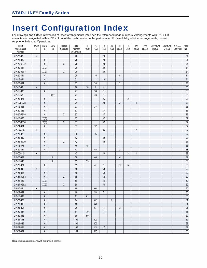
36
STAR-LINE® Family Series
Insert MOD MOD MOD Radsok Total 18 16 12 10 8 4 1/0 4/0 350 MCM 500MCM 646-777 PageArrangement I II III Contacts Number (0.75) (1.5) (4.0) (6.0) (10.0) (250) (50.0) (120.0) (185.0) (240.0) (300-400) No.
Number of Contacts
ZP-20-32 X 20 20 54
ZP-20-332 X 20 20 54
ZP-20-R332 X X 20 20 54
ZP-20-387 X(G) 20 20 54
ZP-20-R387 X(G) X 20 20 54
ZP-20-334 X 20 16 4 54
ZP-16-344 X 21 11 10 54
ZP-20-331 X 22 20 2 55
ZP-16-37 X 26 18 4 4 55
ZP-16-335 X 27 24 3 55
ZP-16-673 X(G) 27 24 3 55
ZP-20-374 X 27 25 2 56
ZP-C28-328 X 29 23 2 4 56
ZP-16-321 X 37 37 56
ZP-20-386 X 37 37 56
ZP-20-R386 X X 37 37 56
ZP-20-350 X(G) 37 37 57
ZP-20-R350 X(G) X 37 37 57
ZP-24-371 X 37 37 57
ZP-C24-36 X 37 35 2 57
ZP-20-323 X 38 35 3 57
ZP-28-339 X 42 42 58
ZP-28-R339 X X 42 42 58
ZP-16-371 X 46 45 1 58
ZP-20-354 X 47 45 2 58
ZP-C28-15 X 47 43 3 1 58
ZP-20-673 X 50 46 4 59
ZP-16-640 X 55 55 59
ZP-28-324 X 55 41 5 3 6 59
ZP-24-84 X 58 58 59
ZP-24-384 X 58 58 59
ZP-24-R384 X X 58 58 59
ZP-24-352 X(G) 58 58 60
ZP-24-R352 X(G) X 58 58 60
ZP-20-35 X 60 60 60
ZP-24-331 X 60 53 7 60
ZP-16-333 X 61 61 60
ZP-20-329 X 64 62 2 61
ZP-20-313 X 68 68 61
ZP-24-354 X 75 61 11 3 61
ZP-20-344 X 81 70 11 61
ZP-20-345 X 90 90 62
ZP-24-313 X 100 100 62
ZP-24-385 X 100 100 62
ZP-28-314 X 100 83 17 63
ZP-28-322 X 143 143 63
Insert Configuration IndexFor drawings and further information of insert arrangements listed see the referenced page numbers. Arrangements with RADSOKcontacts are designated with an ‘R’ in front of the dash number in the part number. For availability of other arrangements, consultAmphenol Industrial Operations.
(G) depicts arrangement with grounded contact
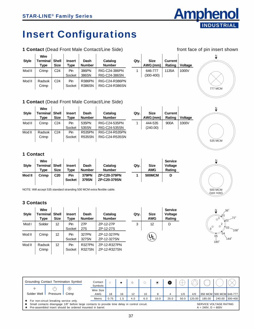
AmphenolINDUSTRIAL
37
ContactSymbols
Wire SizeAWG 18 16 12 10 8 4 1/0 4/0 350 MCM 500 MCM 646-777
Metric 0.75 1.5 4.0 6.0 10.0 25.0 50.0 120.00 185.00 240.00 300-400
STAR-LINE® Family Series
INDUSTRIAL
Insert Configurations1 Contact (Dead Front Male Contact/Line Side)
WireStyle Terminal Shell Insert Dash Catalog Qty. Size Current
Type Size Type Number Number AWG (mm) Rating Voltage
Mod II Crimp C24 Pin 386PN RIG-C24-386PN 1 646-777 1135A 1000VSocket 386SN RIG-C24-386SN (300-400)
Mod II Radsok C24 Pin R386PN RIG-C24-R386PNCrimp Socket R386SN RIG-C24-R386SN
front face of pin insert shownN
777 MCM
1 Contact (Dead Front Male Contact/Line Side)
WireStyle Terminal Shell Insert Dash Catalog Qty. Size Current
Type Size Type Number Number AWG (mm) Rating Voltage
Mod II Crimp C24 Pin 535PN RIG-C24-535PN 1 444-535 900A 1000VSocket 535SN RIG-C24-535SN (240.00)
Mod II Radsok C24 Pin R535PN RIG-C24-R535PNCrimp Socket R535SN RIG-C24-R535SN
N
535 MCM
1 ContactWire Service
Style Terminal Shell Insert Dash Catalog Qty. Size VoltageType Size Type Number Number AWG Rating
Mod II Crimp C20 Pin 379PN ZP-C20-379PN 1 500MCM DSocket 379SN ZP-C20-379SN
N
500 MCM(see note)
3 ContactsWire Service
Style Terminal Shell Insert Dash Catalog Qty. Size VoltageType Size Type Number Number AWG Rating
Mod I Solder 12 Pin 27P ZP-12-27P 3 12 DSocket 27S ZP-12-27S
Mod II Crimp 12 Pin 327PN ZP-12-327PNSocket 327SN ZP-12-327SN
Mod II Radsok 12 Pin R327PN ZP-12-R327PNCrimp Socket R327SN ZP-12-R327SN
Grounding Contact Termination Symbol
Solder Well Pressure Crimp
✦ For non-circuit breaking service only.✱ Small contacts disengage 1/8” before large contacts to provide time delay in control circuit.★ Pre-assembled insert should be ordered mounted in barrel.
N
2
3
101
36o
0272o
03108o
04
144o05
180o
UL®
NOTE: Will accept 535 standard stranding 500 MCM extra flexible cable.
SERVICE VOLTAGE RATINGA = 240V, D = 600V
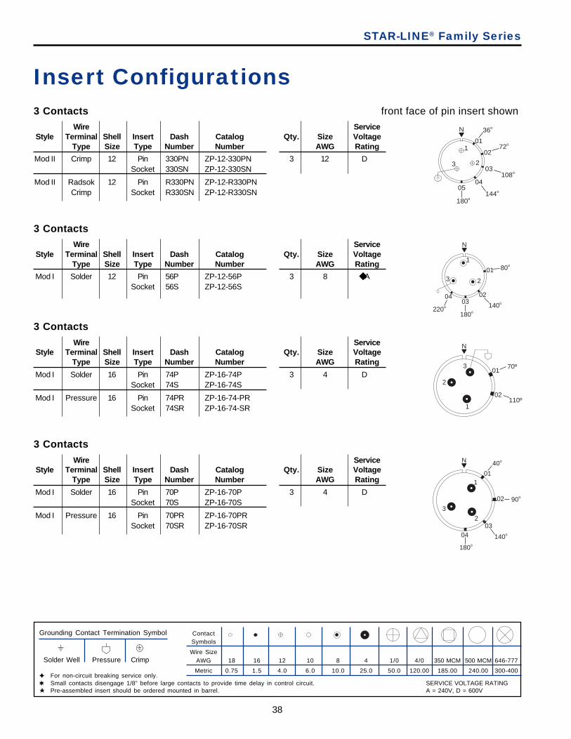
38
STAR-LINE® Family Series
Insert Configurations3 Contacts
Wire ServiceStyle Terminal Shell Insert Dash Catalog Qty. Size Voltage
Type Size Type Number Number AWG Rating
Mod II Crimp 12 Pin 330PN ZP-12-330PN 3 12 DSocket 330SN ZP-12-330SN
Mod II Radsok 12 Pin R330PN ZP-12-R330PNCrimp Socket R330SN ZP-12-R330SN
front face of pin insert shown
3 ContactsWire Service
Style Terminal Shell Insert Dash Catalog Qty. Size VoltageType Size Type Number Number AWG Rating
Mod I Solder 12 Pin 56P ZP-12-56P 3 8 ◆ ASocket 56S ZP-12-56S
3 ContactsWire Service
Style Terminal Shell Insert Dash Catalog Qty. Size VoltageType Size Type Number Number AWG Rating
Mod I Solder 16 Pin 74P ZP-16-74P 3 4 DSocket 74S ZP-16-74S
Mod I Pressure 16 Pin 74PR ZP-16-74-PRSocket 74SR ZP-16-74-SR
3 ContactsWire Service
Style Terminal Shell Insert Dash Catalog Qty. Size VoltageType Size Type Number Number AWG Rating
Mod I Solder 16 Pin 70P ZP-16-70P 3 4 DSocket 70S ZP-16-70S
Mod I Pressure 16 Pin 70PR ZP-16-70PRSocket 70SR ZP-16-70SR
ContactSymbols
Wire SizeAWG 18 16 12 10 8 4 1/0 4/0 350 MCM 500 MCM 646-777
Metric 0.75 1.5 4.0 6.0 10.0 25.0 50.0 120.00 185.00 240.00 300-400
Grounding Contact Termination Symbol
Solder Well Pressure Crimp
✦ For non-circuit breaking service only.✱ Small contacts disengage 1/8” before large contacts to provide time delay in control circuit.★ Pre-assembled insert should be ordered mounted in barrel.
N
1
23
04
220o
180o
140o
80o
01
0203
N
1
2
301
70º
110º02
N
1
2
3
01
02 90o
0304
180o
140o
40o
N
23
101
36o
0272o
03108o
04
144o05
180o
SERVICE VOLTAGE RATINGA = 240V, D = 600V
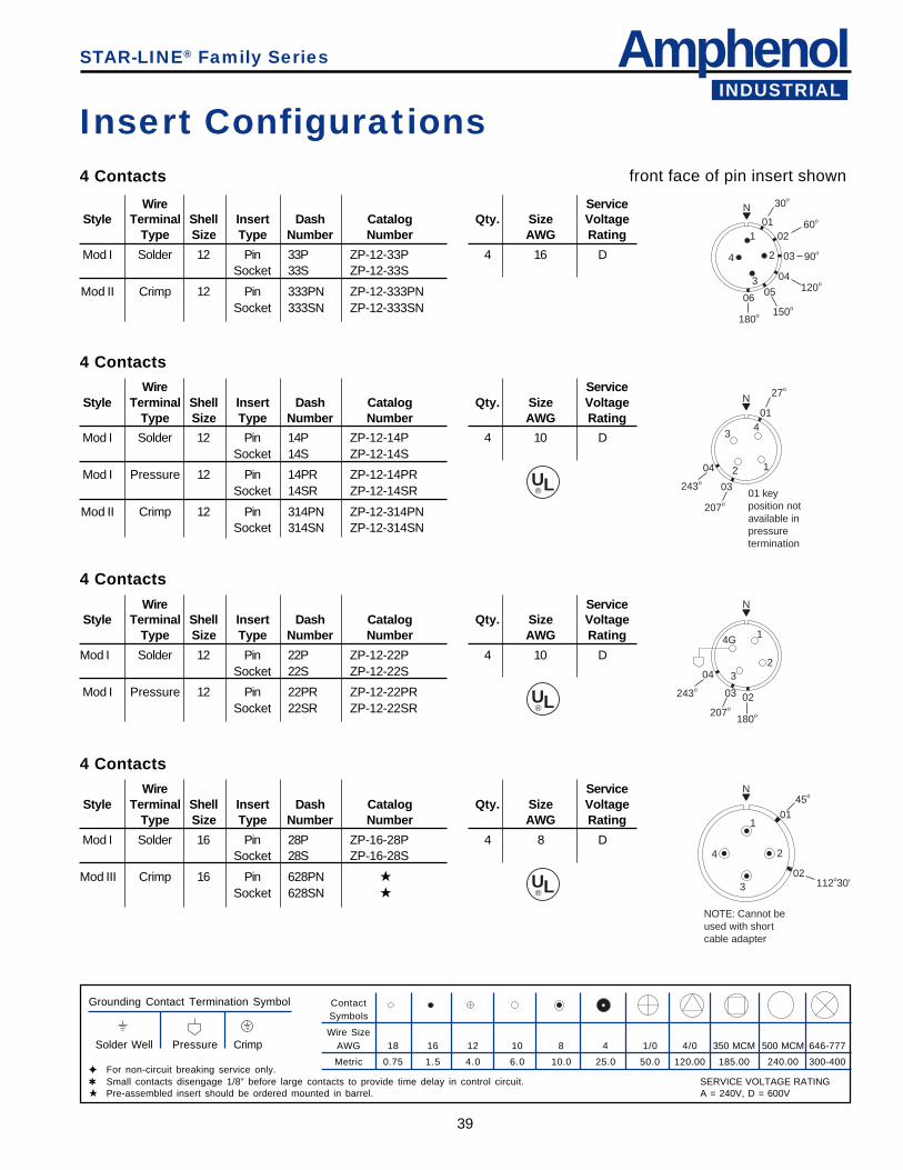
AmphenolINDUSTRIAL
39
STAR-LINE® Family Series
4 Contacts
Wire ServiceStyle Terminal Shell Insert Dash Catalog Qty. Size Voltage
Type Size Type Number Number AWG Rating
Mod I Solder 12 Pin 33P ZP-12-33P 4 16 DSocket 33S ZP-12-33S
Mod II Crimp 12 Pin 333PN ZP-12-333PNSocket 333SN ZP-12-333SN
4 ContactsWire Service
Style Terminal Shell Insert Dash Catalog Qty. Size VoltageType Size Type Number Number AWG Rating
Mod I Solder 12 Pin 14P ZP-12-14P 4 10 DSocket 14S ZP-12-14S
Mod I Pressure 12 Pin 14PR ZP-12-14PRSocket 14SR ZP-12-14SR
Mod II Crimp 12 Pin 314PN ZP-12-314PNSocket 314SN ZP-12-314SN
4 ContactsWire Service
Style Terminal Shell Insert Dash Catalog Qty. Size VoltageType Size Type Number Number AWG Rating
Mod I Solder 12 Pin 22P ZP-12-22P 4 10 DSocket 22S ZP-12-22S
Mod I Pressure 12 Pin 22PR ZP-12-22PRSocket 22SR ZP-12-22SR
4 ContactsWire Service
Style Terminal Shell Insert Dash Catalog Qty. Size VoltageType Size Type Number Number AWG Rating
Mod I Solder 16 Pin 28P ZP-16-28P 4 8 DSocket 28S ZP-16-28S
Mod III Crimp 16 Pin 628PN ★Socket 628SN ★
Insert Configurationsfront face of pin insert shown
ContactSymbols
Wire SizeAWG 18 16 12 10 8 4 1/0 4/0 350 MCM 500 MCM 646-777
Metric 0.75 1.5 4.0 6.0 10.0 25.0 50.0 120.00 185.00 240.00 300-400
Grounding Contact Termination Symbol
Solder Well Pressure Crimp
✦ For non-circuit breaking service only.✱ Small contacts disengage 1/8” before large contacts to provide time delay in control circuit.★ Pre-assembled insert should be ordered mounted in barrel.
N
1
2
3
4
01
30o
0260o
03 90o
04120o
05
150o
180o
06
N
12
34
243o
04
0301 keyposition not available in pressuretermination
207o
01
27o
N
1
23
4G
04
243o 03
207o
02
180o
N
1
2
3
4
01
45o
02
NOTE: Cannot be used with shortcable adapter
112o30'
UL®
UL®
UL®
SERVICE VOLTAGE RATINGA = 240V, D = 600V
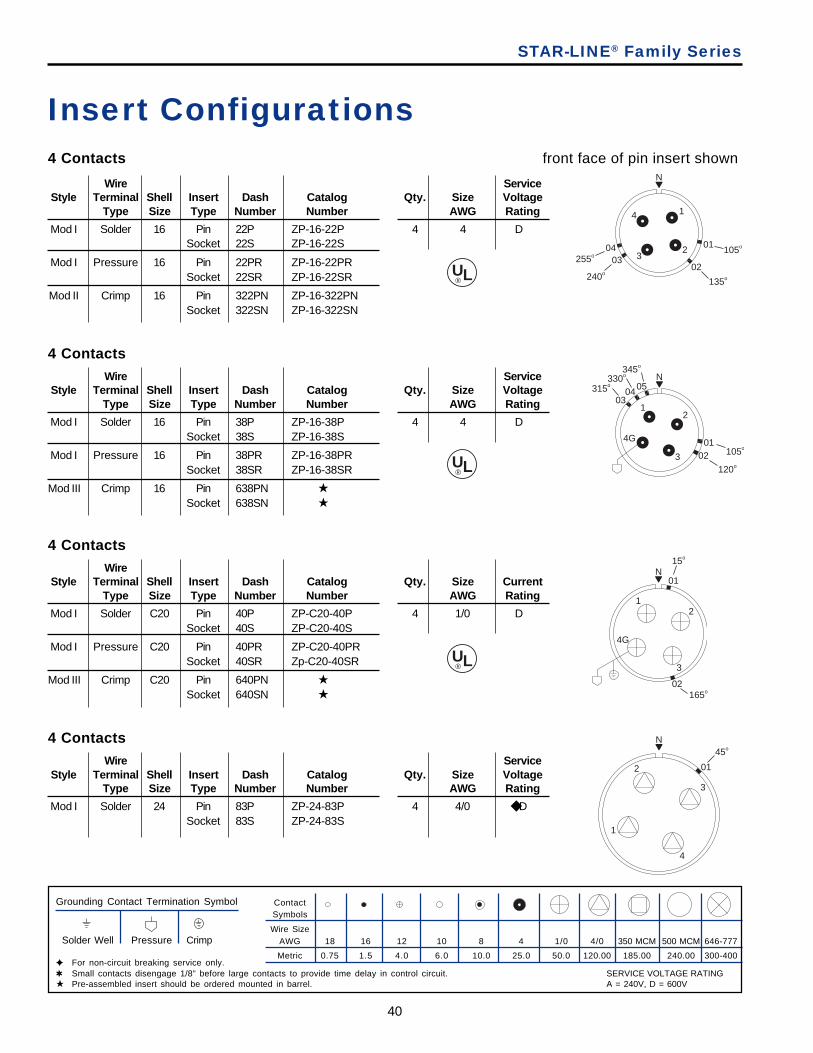
40
STAR-LINE® Family Series
4 Contacts
Wire ServiceStyle Terminal Shell Insert Dash Catalog Qty. Size Voltage
Type Size Type Number Number AWG Rating
Mod I Solder 16 Pin 22P ZP-16-22P 4 4 DSocket 22S ZP-16-22S
Mod I Pressure 16 Pin 22PR ZP-16-22PRSocket 22SR ZP-16-22SR
Mod II Crimp 16 Pin 322PN ZP-16-322PNSocket 322SN ZP-16-322SN
Insert Configurationsfront face of pin insert shown
4 ContactsWire Service
Style Terminal Shell Insert Dash Catalog Qty. Size VoltageType Size Type Number Number AWG Rating
Mod I Solder 16 Pin 38P ZP-16-38P 4 4 DSocket 38S ZP-16-38S
Mod I Pressure 16 Pin 38PR ZP-16-38PRSocket 38SR ZP-16-38SR
Mod III Crimp 16 Pin 638PN ★Socket 638SN ★
4 ContactsWire
Style Terminal Shell Insert Dash Catalog Qty. Size CurrentType Size Type Number Number AWG Rating
Mod I Solder C20 Pin 40P ZP-C20-40P 4 1/0 DSocket 40S ZP-C20-40S
Mod I Pressure C20 Pin 40PR ZP-C20-40PRSocket 40SR Zp-C20-40SR
Mod III Crimp C20 Pin 640PN ★Socket 640SN ★
4 ContactsWire Service
Style Terminal Shell Insert Dash Catalog Qty. Size VoltageType Size Type Number Number AWG Rating
Mod I Solder 24 Pin 83P ZP-24-83P 4 4/0 ◆ DSocket 83S ZP-24-83S
ContactSymbols
Wire SizeAWG 18 16 12 10 8 4 1/0 4/0 350 MCM 500 MCM 646-777
Metric 0.75 1.5 4.0 6.0 10.0 25.0 50.0 120.00 185.00 240.00 300-400
Grounding Contact Termination Symbol
Solder Well Pressure Crimp
✦ For non-circuit breaking service only.✱ Small contacts disengage 1/8” before large contacts to provide time delay in control circuit.★ Pre-assembled insert should be ordered mounted in barrel.
UL®
UL®
UL®
N
1
23
4
01105o
02
135o
0403
240o
255o
N
12
3
4G 01105o
120o
02
315o330o
345o
0504
03
N
1
2
3
01
45o
4
N
12
3
4G
02165o
01
15o
SERVICE VOLTAGE RATINGA = 240V, D = 600V
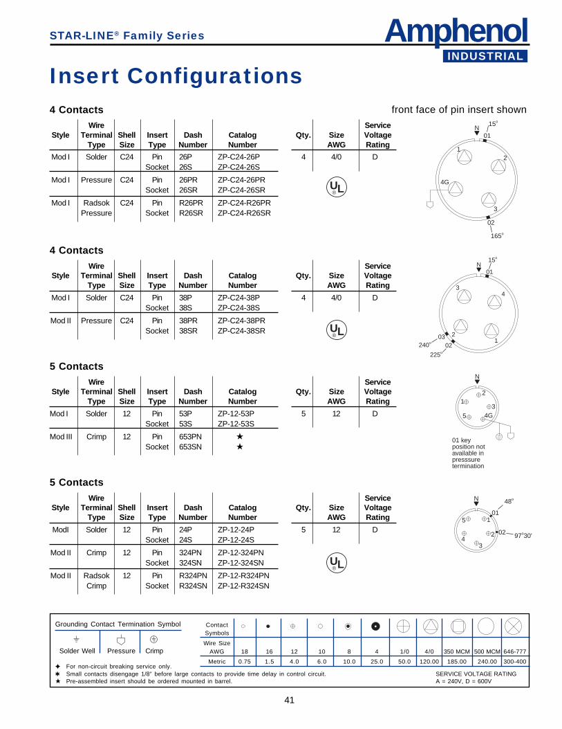
AmphenolINDUSTRIAL
41
STAR-LINE® Family Series
4 ContactsWire Service
Style Terminal Shell Insert Dash Catalog Qty. Size VoltageType Size Type Number Number AWG Rating
Mod I Solder C24 Pin 26P ZP-C24-26P 4 4/0 DSocket 26S ZP-C24-26S
Mod I Pressure C24 Pin 26PR ZP-C24-26PRSocket 26SR ZP-C24-26SR
Mod I Radsok C24 Pin R26PR ZP-C24-R26PRPressure Socket R26SR ZP-C24-R26SR
Insert Configurationsfront face of pin insert shown
4 ContactsWire Service
Style Terminal Shell Insert Dash Catalog Qty. Size VoltageType Size Type Number Number AWG Rating
Mod I Solder C24 Pin 38P ZP-C24-38P 4 4/0 DSocket 38S ZP-C24-38S
Mod II Pressure C24 Pin 38PR ZP-C24-38PRSocket 38SR ZP-C24-38SR
5 ContactsWire Service
Style Terminal Shell Insert Dash Catalog Qty. Size VoltageType Size Type Number Number AWG Rating
Mod I Solder 12 Pin 53P ZP-12-53P 5 12 DSocket 53S ZP-12-53S
Mod III Crimp 12 Pin 653PN ★
Socket 653SN ★
5 ContactsWire Service
Style Terminal Shell Insert Dash Catalog Qty. Size VoltageType Size Type Number Number AWG Rating
ModI Solder 12 Pin 24P ZP-12-24P 5 12 DSocket 24S ZP-12-24S
Mod II Crimp 12 Pin 324PN ZP-12-324PNSocket 324SN ZP-12-324SN
Mod II Radsok 12 Pin R324PN ZP-12-R324PNCrimp Socket R324SN ZP-12-R324SN
ContactSymbols
Wire SizeAWG 18 16 12 10 8 4 1/0 4/0 350 MCM 500 MCM 646-777
Metric 0.75 1.5 4.0 6.0 10.0 25.0 50.0 120.00 185.00 240.00 300-400
Grounding Contact Termination Symbol
Solder Well Pressure Crimp
✦ For non-circuit breaking service only.✱ Small contacts disengage 1/8” before large contacts to provide time delay in control circuit.★ Pre-assembled insert should be ordered mounted in barrel.
N
1203
02
225o
240o
34
01
15o
N
12
34G5
01 keyposition notavailable inpresssuretermination
N
1
2
34
501
48o
02 97o30'
UL®
UL®
UL®
N
12
3
02
165o
4G
01
15o
SERVICE VOLTAGE RATINGA = 240V, D = 600V
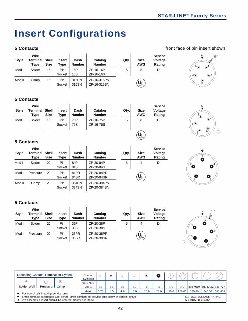
42
STAR-LINE® Family Series
5 Contacts
Wire ServiceStyle Terminal Shell Insert Dash Catalog Qty. Size Voltage
Type Size Type Number Number AWG Rating
Mod I Solder 16 Pin 16P ZP-16-16P 5 8 DSocket 16S ZP-16-16S
Mod II Crimp 16 Pin 316PN ZP-16-316PNSocket 316SN ZP-16-316SN
Insert Configurationsfront face of pin insert shown
5 ContactsWire Service
Style Terminal Shell Insert Dash Catalog Qty. Size VoltageType Size Type Number Number AWG Rating
Mod I Solder 16 Pin 75P ZP-16-75P 5 8 DSocket 75S ZP-16-75S
5 ContactsWire Service
Style Terminal Shell Insert Dash Catalog Qty. Size VoltageType Size Type Number Number AWG Rating
Mod I Solder 20 Pin 84P ZP-20-84P 5 4 DSocket 84S ZP-20-84S
Mod I Pressure 20 Pin 84PR ZP-20-84PRSocket 84SR ZP-20-84SR
Mod II Crimp 20 Pin 384PN ZP-20-384PNSocket 384SN ZP-20-384SN
5 ContactsWire Service
Style Terminal Shell Insert Dash Catalog Qty. Size VoltageType Size Type Number Number AWG Rating
Mod I Solder 20 Pin 38P ZP-20-38P 5 4 DSocket 38S ZP-20-38S
Mod I Pressure 20 Pin 38PR ZP-20-38PRSocket 38SR ZP-20-38SR
ContactSymbols
Wire SizeAWG 18 16 12 10 8 4 1/0 4/0 350 MCM 500 MCM 646-777
Metric 0.75 1.5 4.0 6.0 10.0 25.0 50.0 120.00 185.00 240.00 300-400
Grounding Contact Termination Symbol
Solder Well Pressure Crimp
✦ For non-circuit breaking service only.✱ Small contacts disengage 1/8” before large contacts to provide time delay in control circuit.★ Pre-assembled insert should be ordered mounted in barrel.
UL®
UL®
UL®
UL®
N
1
2
3
4
5
01
36o
N
1
23
4G5
N
1
2
3
4
5
N
101
15o
2
3
4G
5
SERVICE VOLTAGE RATINGA = 240V, D = 600V
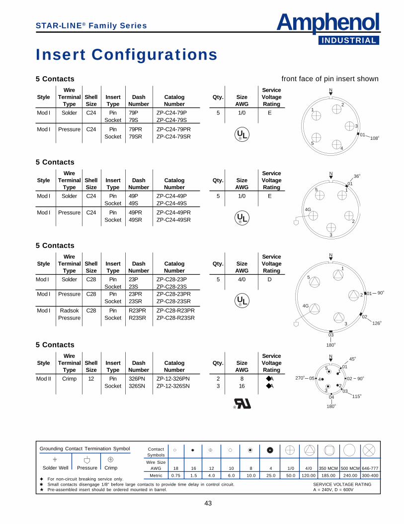
AmphenolINDUSTRIAL
43
STAR-LINE® Family Series
5 ContactsWire Service
Style Terminal Shell Insert Dash Catalog Qty. Size VoltageType Size Type Number Number AWG Rating
Mod I Solder C24 Pin 79P ZP-C24-79P 5 1/0 ESocket 79S ZP-C24-79S
Mod I Pressure C24 Pin 79PR ZP-C24-79PRSocket 79SR ZP-C24-79SR
Insert Configurationsfront face of pin insert shown
5 ContactsWire Service
Style Terminal Shell Insert Dash Catalog Qty. Size VoltageType Size Type Number Number AWG Rating
Mod I Solder C24 Pin 49P ZP-C24-49P 5 1/0 ESocket 49S ZP-C24-49S
Mod I Pressure C24 Pin 49PR ZP-C24-49PRSocket 49SR ZP-C24-49SR
5 ContactsWire Service
Style Terminal Shell Insert Dash Catalog Qty. Size VoltageType Size Type Number Number AWG Rating
Mod I Solder C28 Pin 23P ZP-C28-23P 5 4/0 DSocket 23S ZP-C28-23S
Mod I Pressure C28 Pin 23PR ZP-C28-23PRSocket 23SR ZP-C28-23SR
Mod I Radsok C28 Pin R23PR ZP-C28-R23PRPressure Socket R23SR ZP-C28-R23SR
5 ContactsWire Service
Style Terminal Shell Insert Dash Catalog Qty. Size VoltageType Size Type Number Number AWG Rating
Mod II Crimp 12 Pin 326PN ZP-12-326PN 2 8 ◆ ASocket 326SN ZP-12-326SN 3 16 ◆ A
ContactSymbols
Wire SizeAWG 18 16 12 10 8 4 1/0 4/0 350 MCM 500 MCM 646-777
Metric 0.75 1.5 4.0 6.0 10.0 25.0 50.0 120.00 185.00 240.00 300-400
Grounding Contact Termination Symbol
Solder Well Pressure Crimp
✦ For non-circuit breaking service only.✱ Small contacts disengage 1/8” before large contacts to provide time delay in control circuit.★ Pre-assembled insert should be ordered mounted in barrel.
N
12
3
45
01108o
UL®
UL®
UL®
N
101
36o
2
3
4G
5
N
1
90o01
02126o
03
180o
2
3
4G
5
N
1
23
4
5 01
45o
02 90o
03115o
04
180o
05270o
®
SERVICE VOLTAGE RATINGA = 240V, D = 600V
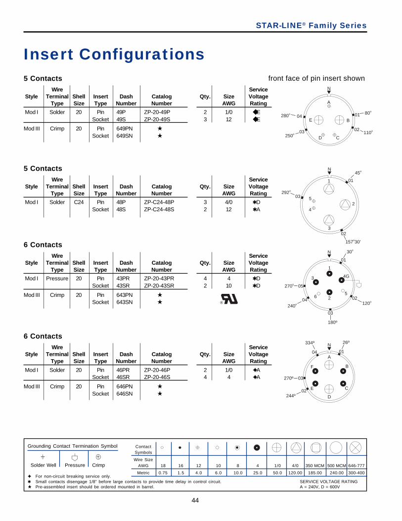
44
STAR-LINE® Family Series
5 ContactsWire Service
Style Terminal Shell Insert Dash Catalog Qty. Size VoltageType Size Type Number Number AWG Rating
Mod I Solder 20 Pin 49P ZP-20-49P 2 1/0 ◆ ESocket 49S ZP-20-49S 3 12 ◆ E
Mod III Crimp 20 Pin 649PN ★
Socket 649SN ★
Insert Configurationsfront face of pin insert shown
5 ContactsWire Service
Style Terminal Shell Insert Dash Catalog Qty. Size VoltageType Size Type Number Number AWG Rating
Mod I Solder C24 Pin 48P ZP-C24-48P 3 4/0 ✱ DSocket 48S ZP-C24-48S 2 12 ✱ A
6 ContactsWire Service
Style Terminal Shell Insert Dash Catalog Qty. Size VoltageType Size Type Number Number AWG Rating
Mod I Pressure 20 Pin 43PR ZP-20-43PR 4 4 ✱ DSocket 43SR ZP-20-43SR 2 10 ✱ D
Mod III Crimp 20 Pin 643PN ★
Socket 643SN ★
6 ContactsWire Service
Style Terminal Shell Insert Dash Catalog Qty. Size VoltageType Size Type Number Number AWG Rating
Mod I Solder 20 Pin 46PR ZP-20-46P 2 1/0 ✦ ASocket 46SR ZP-20-46S 4 4 ✦ A
Mod III Crimp 20 Pin 646PN ★
Socket 646SN ★
ContactSymbols
Wire SizeAWG 18 16 12 10 8 4 1/0 4/0 350 MCM 500 MCM 646-777
Metric 0.75 1.5 4.0 6.0 10.0 25.0 50.0 120.00 185.00 240.00 300-400
Grounding Contact Termination Symbol
Solder Well Pressure Crimp
✦ For non-circuit breaking service only.✱ Small contacts disengage 1/8” before large contacts to provide time delay in control circuit.★ Pre-assembled insert should be ordered mounted in barrel.
N
A
B
CD
E01 80o
02110o03
250o
04280o
N
1
2
3
4
5
01
45o
02
157o30'
03292o
N
1
01
30o
02120o
03
180º
04
05270o
240o
2
3 4G
56
N
A
B
C
D
E
F
01
02244º
03270º
04
334º 26º
®
SERVICE VOLTAGE RATINGA = 240V, D = 600V
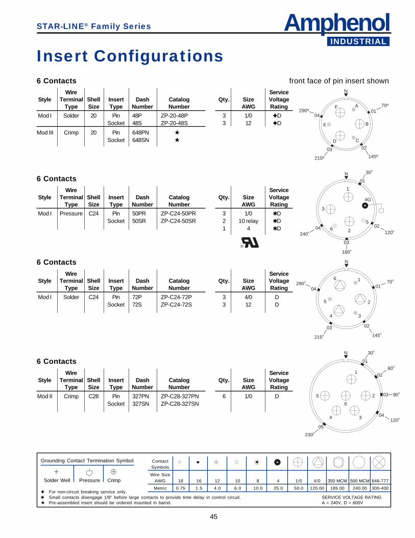
AmphenolINDUSTRIAL
45
STAR-LINE® Family Series
Insert Configurationsfront face of pin insert shown6 Contacts
Wire ServiceStyle Terminal Shell Insert Dash Catalog Qty. Size Voltage
Type Size Type Number Number AWG Rating
Mod I Solder 20 Pin 48P ZP-20-48P 3 1/0 ✦ DSocket 48S ZP-20-48S 3 12 ✦ D
Mod III Crimp 20 Pin 648PN ★
Socket 648SN ★
6 ContactsWire Service
Style Terminal Shell Insert Dash Catalog Qty. Size VoltageType Size Type Number Number AWG Rating
Mod I Pressure C24 Pin 50PR ZP-C24-50PR 3 1/0 ✱ DSocket 50SR ZP-C24-50SR 2 10 relay ✱ D
1 4 ✱ D
6 ContactsWire Service
Style Terminal Shell Insert Dash Catalog Qty. Size VoltageType Size Type Number Number AWG Rating
Mod I Solder C24 Pin 72P ZP-C24-72P 3 4/0 DSocket 72S ZP-C24-72S 3 12 D
6 ContactsWire Service
Style Terminal Shell Insert Dash Catalog Qty. Size VoltageType Size Type Number Number AWG Rating
Mod II Crimp C28 Pin 327PN ZP-C28-327PN 6 1/0 DSocket 327SN ZP-C28-327SN
ContactSymbols
Wire SizeAWG 18 16 12 10 8 4 1/0 4/0 350 MCM 500 MCM 646-777
Metric 0.75 1.5 4.0 6.0 10.0 25.0 50.0 120.00 185.00 240.00 300-400
Grounding Contact Termination Symbol
Solder Well Pressure Crimp
✦ For non-circuit breaking service only.✱ Small contacts disengage 1/8” before large contacts to provide time delay in control circuit.★ Pre-assembled insert should be ordered mounted in barrel.
N
A
B
CD
E
F01
70º
145º
0203
215º
04290º
N
1
2
3
4G
56
01
30o
02120o
03
180o
04240o
N
1
2
34
5
6
0170o
02
04290o
215o
03
145o
N
1
2
34
5
6
01
30o
0260o
03 90o
04120o
05
230o
®
SERVICE VOLTAGE RATINGA = 240V, D = 600V
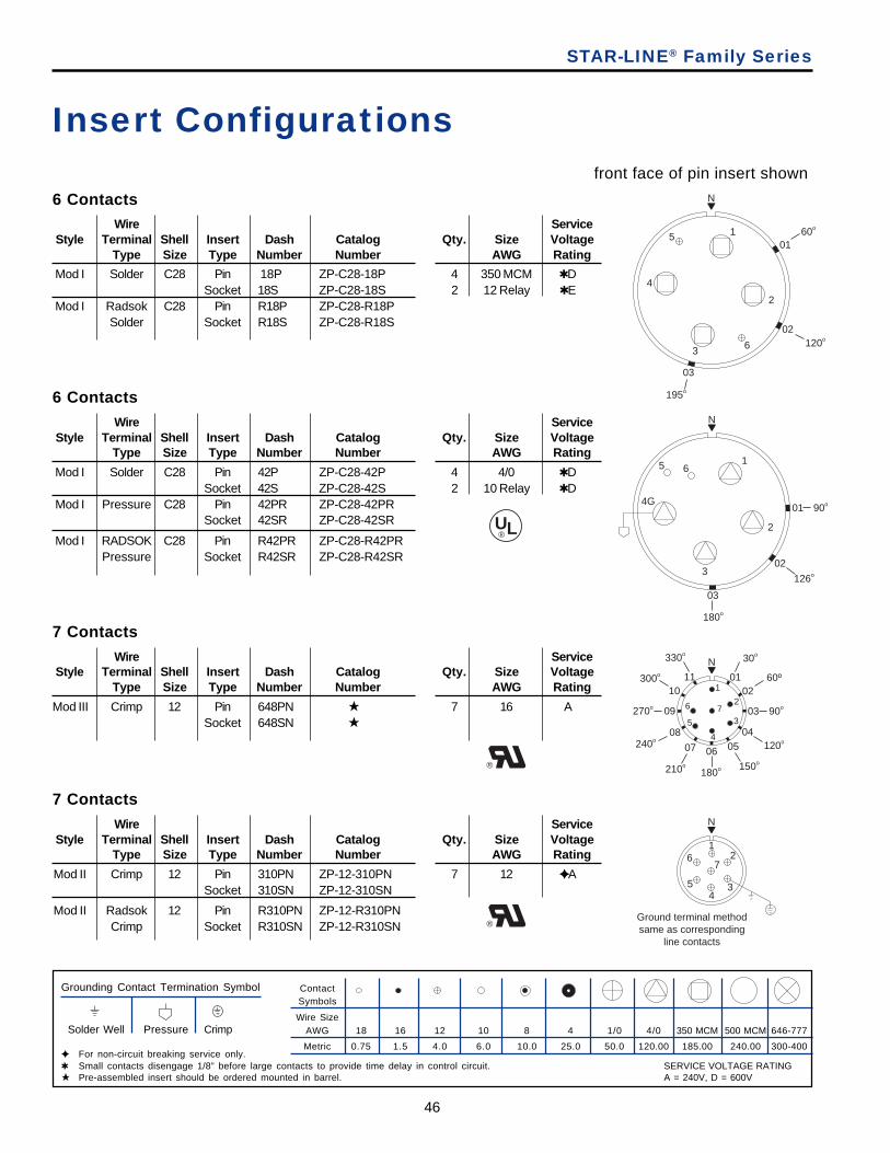
46
Insert Configurationsfront face of pin insert shown
6 ContactsWire Service
Style Terminal Shell Insert Dash Catalog Qty. Size VoltageType Size Type Number Number AWG Rating
Mod I Solder C28 Pin 42P ZP-C28-42P 4 4/0 ✱ DSocket 42S ZP-C28-42S 2 10 Relay ✱ D
Mod I Pressure C28 Pin 42PR ZP-C28-42PRSocket 42SR ZP-C28-42SR
Mod I RADSOK C28 Pin R42PR ZP-C28-R42PRPressure Socket R42SR ZP-C28-R42SR
7 ContactsWire Service
Style Terminal Shell Insert Dash Catalog Qty. Size VoltageType Size Type Number Number AWG Rating
Mod III Crimp 12 Pin 648PN ★ 7 16 ASocket 648SN ★
7 ContactsWire Service
Style Terminal Shell Insert Dash Catalog Qty. Size VoltageType Size Type Number Number AWG Rating
Mod II Crimp 12 Pin 310PN ZP-12-310PN 7 12 ✦ ASocket 310SN ZP-12-310SN
Mod II Radsok 12 Pin R310PN ZP-12-R310PNCrimp Socket R310SN ZP-12-R310SN
ContactSymbols
Wire SizeAWG 18 16 12 10 8 4 1/0 4/0 350 MCM 500 MCM 646-777
Metric 0.75 1.5 4.0 6.0 10.0 25.0 50.0 120.00 185.00 240.00 300-400
Grounding Contact Termination Symbol
Solder Well Pressure Crimp
✦ For non-circuit breaking service only.✱ Small contacts disengage 1/8” before large contacts to provide time delay in control circuit.★ Pre-assembled insert should be ordered mounted in barrel.
6 ContactsWire Service
Style Terminal Shell Insert Dash Catalog Qty. Size VoltageType Size Type Number Number AWG Rating
Mod I Solder C28 Pin 18P ZP-C28-18P 4 350 MCM ✱ DSocket 18S ZP-C28-18S 2 12 Relay ✱ E
Mod I Radsok C28 Pin R18P ZP-C28-R18PSolder Socket R18S ZP-C28-R18S
N
1
2
3
4
5
6
0160o
02
03
195o
120o
N
1
2
3
4G
5 6
01 90o
02
126o
03
180o
N
1
2
3
4
5
6 7
01
30o
0260º
03 90o
04120o
05
150o
06
180o
07
210o
08240o
09270o
10300o 11
330o
N
Ground terminal methodsame as corresponding
line contacts
12
34
5
67
UL®
®
®
STAR-LINE® Family Series
SERVICE VOLTAGE RATINGA = 240V, D = 600V
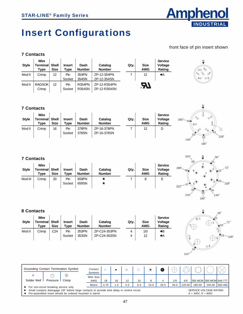
AmphenolINDUSTRIAL
47
Insert Configurationsfront face of pin insert shown
Mod II Crimp 12 Pin 354PN ZP-12-354PN 7 12 ✦ ASocket 354SN ZP-12-354SN
Mod II RADSOK 12 Pin R354PN ZP-12-R354PNCrimp Socket R354SN ZP-12-R354SN
7 ContactsWire Service
Style Terminal Shell Insert Dash Catalog Qty. Size VoltageType Size Type Number Number AWG Rating
Mod II Crimp 16 Pin 378PN ZP-16-378PN 7 12 DSocket 378SN ZP-16-378SN
7 ContactsWire Service
Style Terminal Shell Insert Dash Catalog Qty. Size VoltageType Size Type Number Number AWG Rating
Mod III Crimp 20 Pin 659PN ★ 7 8 ESocket 659SN ★
8 ContactsWire Service
Style Terminal Shell Insert Dash Catalog Qty. Size VoltageType Size Type Number Number AWG Rating
Mod II Crimp C24 Pin 353PN ZP-C24-353PN 4 1/0 ✦ BSocket 353SN ZP-C24-353SN 4 12 ✦ A
ContactSymbols
Wire SizeAWG 18 16 12 10 8 4 1/0 4/0 350 MCM 500 MCM 646-777
Metric 0.75 1.5 4.0 6.0 10.0 25.0 50.0 120.00 185.00 240.00 300-400
Grounding Contact Termination Symbol
Solder Well Pressure Crimp
✦ For non-circuit breaking service only.✱ Small contacts disengage 1/8” before large contacts to provide time delay in control circuit.★ Pre-assembled insert should be ordered mounted in barrel.
7 ContactsWire Service
Style Terminal Shell Insert Dash Catalog Qty. Size VoltageType Size Type Number Number AWG Rating
®
N
12 3
4
56
7
N
12
3
45
6
7
01
228o02
180o
03
140o
04280o
N
1
2
3
45
67
01
36o
0272o
03108o
04
144o05
180o
06
216o
07252o
08288o
09
324o
N
1
2
3
45
6
7
8 01
30o
0271o
03 108o
04
222o
STAR-LINE® Family Series
SERVICE VOLTAGE RATINGA = 240V, D = 600V

48
8 ContactsWire Service
Style Terminal Shell Insert Dash Catalog Qty. Size VoltageType Size Type Number Number AWG Rating
Mod I Solder C28 Pin 21P ZP-C28-21P 4 350 MCM ✱ DSocket 21S ZP-C28-21S 4 12 Relay ✱ E
Mod I Radsok C28 Pin R21P ZP-C28-R21PSolder Socket R21S ZP-C28-R21S
Insert Configurationsfront face of pin insert shown
ContactSymbols
Wire SizeAWG 18 16 12 10 8 4 1/0 4/0 350 MCM 500 MCM 646-777
Metric 0.75 1.5 4.0 6.0 10.0 25.0 50.0 120.00 185.00 240.00 300-400
Grounding Contact Termination Symbol
Solder Well Pressure Crimp
✦ For non-circuit breaking service only.✱ Small contacts disengage 1/8” before large contacts to provide time delay in control circuit.★ Pre-assembled insert should be ordered mounted in barrel.
8 ContactsWire Service
Style Terminal Shell Insert Dash Catalog Qty. Size VoltageType Size Type Number Number AWG Rating
Mod I Solder C28 Pin 43P ZP-C28-43P 4 350 MCM ✱ DSocket 43S ZP-C28-43S 4 12 Relay ✱ E
Mod I Radsok C28 Pin R43P ZP-C28-R43PSolder Socket R43S ZP-C28-R43S
9 ContactsWire Service
Style Terminal Shell Insert Dash Catalog Qty. Size VoltageType Size Type Number Number AWG Rating
Mod I Solder 16 Pin 29P ZP-16-29P 1 4 ✦ DSocket 29S ZP-16-29S 8 16 ✦ D
9 ContactsWire Service
Style Terminal Shell Insert Dash Catalog Qty. Size VoltageType Size Type Number Number AWG Rating
Mod II Crimp 16 Pin 346PN ZP-16-346PN 6 12 ASocket 346SN ZP-16-346SN 3 8 A
N
1
2
3
4
5
6
7
8
0160o
N
1
2
3
4G5
67
8
0175o
N
12
3
45
6
7
8
9
0160o
02120o
03
180o
04240o
05300o
N
12
3
456
7
89
01
30o
0260o
03 90o
04120o05
230o
®
STAR-LINE® Family Series
SERVICE VOLTAGE RATINGA = 240V, D = 600V
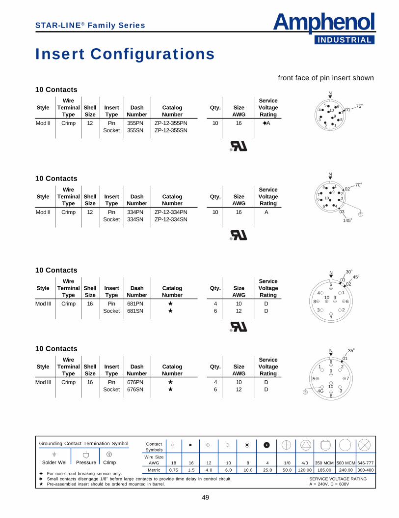
AmphenolINDUSTRIAL
49
Insert Configurationsfront face of pin insert shown
ContactSymbols
Wire SizeAWG 18 16 12 10 8 4 1/0 4/0 350 MCM 500 MCM 646-777
Metric 0.75 1.5 4.0 6.0 10.0 25.0 50.0 120.00 185.00 240.00 300-400
Grounding Contact Termination Symbol
Solder Well Pressure Crimp
✦ For non-circuit breaking service only.✱ Small contacts disengage 1/8” before large contacts to provide time delay in control circuit.★ Pre-assembled insert should be ordered mounted in barrel.
10 ContactsWire Service
Style Terminal Shell Insert Dash Catalog Qty. Size VoltageType Size Type Number Number AWG Rating
Mod II Crimp 12 Pin 355PN ZP-12-355PN 10 16 ✦ ASocket 355SN ZP-12-355SN
®
10 ContactsWire Service
Style Terminal Shell Insert Dash Catalog Qty. Size VoltageType Size Type Number Number AWG Rating
Mod II Crimp 12 Pin 334PN ZP-12-334PN 10 16 ASocket 334SN ZP-12-334SN
®
N
12
3
45 6
7
89
10 0175o
N
1
23
45
67
89
10
0270o
03
145o
10 ContactsWire Service
Style Terminal Shell Insert Dash Catalog Qty. Size VoltageType Size Type Number Number AWG Rating
Mod III Crimp 16 Pin 681PN ★ 4 10 DSocket 681SN ★ 6 12 D
®
N
1
23
4
5
6
7
8910
01
30o
02
45o
10 ContactsWire Service
Style Terminal Shell Insert Dash Catalog Qty. Size VoltageType Size Type Number Number AWG Rating
Mod III Crimp 16 Pin 676PN ★ 4 10 DSocket 676SN ★ 6 12 D
N
1 2
34G
5
6
7
8
9
10
01
35o
STAR-LINE® Family Series
SERVICE VOLTAGE RATINGA = 240V, D = 600V
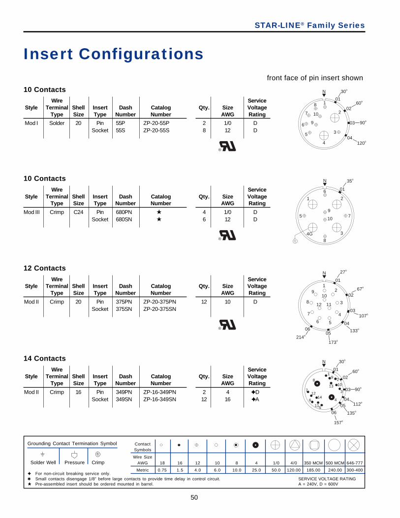
50
Insert Configurationsfront face of pin insert shown
ContactSymbols
Wire SizeAWG 18 16 12 10 8 4 1/0 4/0 350 MCM 500 MCM 646-777
Metric 0.75 1.5 4.0 6.0 10.0 25.0 50.0 120.00 185.00 240.00 300-400
Grounding Contact Termination Symbol
Solder Well Pressure Crimp
✦ For non-circuit breaking service only.✱ Small contacts disengage 1/8” before large contacts to provide time delay in control circuit.★ Pre-assembled insert should be ordered mounted in barrel.
10 ContactsWire Service
Style Terminal Shell Insert Dash Catalog Qty. Size VoltageType Size Type Number Number AWG Rating
Mod I Solder 20 Pin 55P ZP-20-55P 2 1/0 DSocket 55S ZP-20-55S 8 12 D
®
10 ContactsWire Service
Style Terminal Shell Insert Dash Catalog Qty. Size VoltageType Size Type Number Number AWG Rating
Mod III Crimp C24 Pin 680PN ★ 4 1/0 DSocket 680SN ★ 6 12 D
®
12 ContactsWire Service
Style Terminal Shell Insert Dash Catalog Qty. Size VoltageType Size Type Number Number AWG Rating
Mod II Crimp 20 Pin 375PN ZP-20-375PN 12 10 DSocket 375SN ZP-20-375SN
®
N
1
2
3
4
5
6
7
8
9
10
01
30o
0260o
03
04120o
90o
STAR-LINE® Family Series
N
1 2
34G
5
6
7
8
9
10
01
35o
N
12
3
4
56
7
8
910
1112
01
27o
0267o
03107o
04
133o
05
173o
06
214o
14 ContactsWire Service
Style Terminal Shell Insert Dash Catalog Qty. Size VoltageType Size Type Number Number AWG Rating
Mod II Crimp 16 Pin 349PN ZP-16-349PN 2 4 ✦ DSocket 349SN ZP-16-349SN 12 16 ✦ A
N
12
3
4
5
6
7
89
10
11
12
13
14
01
30o
0260o
03 90o
04112o
05
135o06
157o
SERVICE VOLTAGE RATINGA = 240V, D = 600V
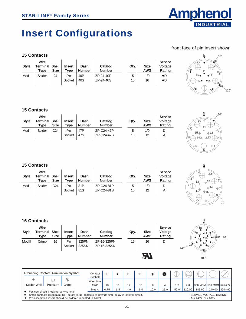
AmphenolINDUSTRIAL
51
Insert Configurationsfront face of pin insert shown
ContactSymbols
Wire SizeAWG 18 16 12 10 8 4 1/0 4/0 350 MCM 500 MCM 646-777
Metric 0.75 1.5 4.0 6.0 10.0 25.0 50.0 120.00 185.00 240.00 300-400
Grounding Contact Termination Symbol
Solder Well Pressure Crimp
✦ For non-circuit breaking service only.✱ Small contacts disengage 1/8” before large contacts to provide time delay in control circuit.★ Pre-assembled insert should be ordered mounted in barrel.
STAR-LINE® Family Series
15 ContactsWire Service
Style Terminal Shell Insert Dash Catalog Qty. Size VoltageType Size Type Number Number AWG Rating
Mod I Solder 24 Pin 40P ZP-24-40P 5 1/0 ✦ DSocket 40S ZP-24-40S 10 16 ✦ D
15 ContactsWire Service
Style Terminal Shell Insert Dash Catalog Qty. Size VoltageType Size Type Number Number AWG Rating
Mod I Solder C24 Pin 47P ZP-C24-47P 5 1/0 DSocket 47S ZP-C24-47S 10 12 A
15 ContactsWire Service
Style Terminal Shell Insert Dash Catalog Qty. Size VoltageType Size Type Number Number AWG Rating
Mod I Solder C24 Pin 81P ZP-C24-81P 5 1/0 DSocket 81S ZP-C24-81S 10 12 A
®
16 ContactsWire Service
Style Terminal Shell Insert Dash Catalog Qty. Size VoltageType Size Type Number Number AWG Rating
Mod II Crimp 16 Pin 325PN ZP-16-325PN 16 16 DSocket 325SN ZP-16-325SN
N
12
3
4
56
7
8
9
10
11
12
1314
15
01
36o
02126o
N
1
2
3
4
5
67
8
9
10
11
12
1314
15
01
36o
N
1
2
3
4 5
6
7
8
910
11
12 13
14
15
N
1
2
3
456
7
8
9
10
1112
1314
15
16
243o03
02
180o
01 90o
SERVICE VOLTAGE RATINGA = 240V, D = 600V
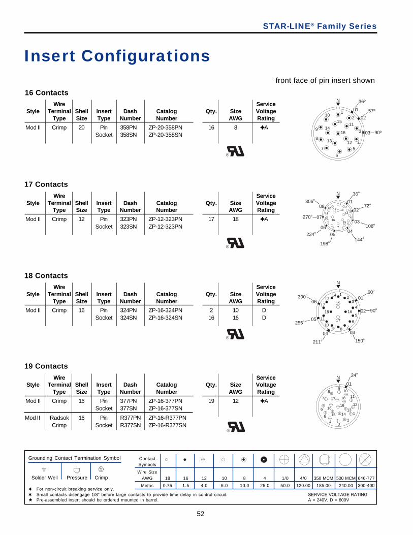
52
STAR-LINE® Family Series
Insert Configurationsfront face of pin insert shown
ContactSymbols
Wire SizeAWG 18 16 12 10 8 4 1/0 4/0 350 MCM 500 MCM 646-777
Metric 0.75 1.5 4.0 6.0 10.0 25.0 50.0 120.00 185.00 240.00 300-400
Grounding Contact Termination Symbol
Solder Well Pressure Crimp
✦ For non-circuit breaking service only.✱ Small contacts disengage 1/8” before large contacts to provide time delay in control circuit.★ Pre-assembled insert should be ordered mounted in barrel.
16 ContactsWire Service
Style Terminal Shell Insert Dash Catalog Qty. Size VoltageType Size Type Number Number AWG Rating
Mod II Crimp 20 Pin 358PN ZP-20-358PN 16 8 ✦ ASocket 358SN ZP-20-358SN
®
17 ContactsWire Service
Style Terminal Shell Insert Dash Catalog Qty. Size VoltageType Size Type Number Number AWG Rating
Mod II Crimp 12 Pin 323PN ZP-12-323PN 17 18 ✦ ASocket 323SN ZP-12-323PN
®
18 ContactsWire Service
Style Terminal Shell Insert Dash Catalog Qty. Size VoltageType Size Type Number Number AWG Rating
Mod II Crimp 16 Pin 324PN ZP-16-324PN 2 10 DSocket 324SN ZP-16-324SN 16 16 D
®
19 ContactsWire Service
Style Terminal Shell Insert Dash Catalog Qty. Size VoltageType Size Type Number Number AWG Rating
Mod II Crimp 16 Pin 377PN ZP-16-377PN 19 12 ✦ ASocket 377SN ZP-16-377SN
Mod II Radsok 16 Pin R377PN ZP-16-R377PNCrimp Socket R377SN ZP-16-R377SN
®
N
12
3
45
6
7
8
9
10
11
1213
14
15
16
01
36º
0257º
03 90º
N
12
3
4
5678
9
10
11
1213
14
1516
17
01
36o
0272o
03108o
04
144o05
198o
234o
06
07270o
08306o
N
12
34
5
6789
10
11
12
1314
15
16
17
18
0160o
02 90o
03
150o
04
211o
05255o
06300o
N
1
01
24o
23
45
6
7
89 10
11
1213
1415
16
17 18
19
SERVICE VOLTAGE RATINGA = 240V, D = 600V
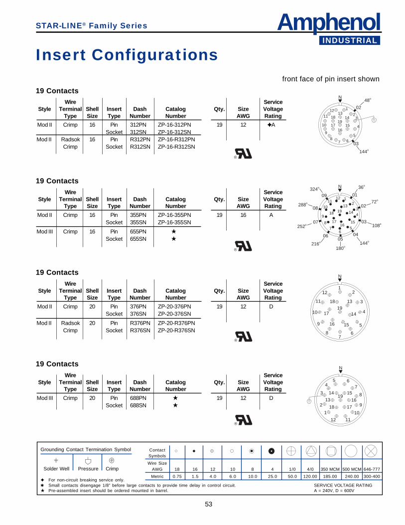
AmphenolINDUSTRIAL
53
STAR-LINE® Family Series
Insert Configurationsfront face of pin insert shown
ContactSymbols
Wire SizeAWG 18 16 12 10 8 4 1/0 4/0 350 MCM 500 MCM 646-777
Metric 0.75 1.5 4.0 6.0 10.0 25.0 50.0 120.00 185.00 240.00 300-400
Grounding Contact Termination Symbol
Solder Well Pressure Crimp
✦ For non-circuit breaking service only.✱ Small contacts disengage 1/8” before large contacts to provide time delay in control circuit.★ Pre-assembled insert should be ordered mounted in barrel.
19 ContactsWire Service
Style Terminal Shell Insert Dash Catalog Qty. Size VoltageType Size Type Number Number AWG Rating
Mod II Crimp 16 Pin 312PN ZP-16-312PN 19 12 ✦ ASocket 312SN ZP-16-312SN
Mod II Radsok 16 Pin R312PN ZP-16-R312PNCrimp Socket R312SN ZP-16-R312SN
19 ContactsWire Service
Style Terminal Shell Insert Dash Catalog Qty. Size VoltageType Size Type Number Number AWG Rating
Mod II Crimp 16 Pin 355PN ZP-16-355PN 19 16 ASocket 355SN ZP-16-355SN
Mod III Crimp 16 Pin 655PN ★
Socket 655SN ★
19 ContactsWire Service
Style Terminal Shell Insert Dash Catalog Qty. Size VoltageType Size Type Number Number AWG Rating
Mod II Crimp 20 Pin 376PN ZP-20-376PN 19 12 DSocket 376SN ZP-20-376SN
Mod II Radsok 20 Pin R376PN ZP-20-R376PNCrimp Socket R376SN ZP-20-R376SN
®
19 ContactsWire Service
Style Terminal Shell Insert Dash Catalog Qty. Size VoltageType Size Type Number Number AWG Rating
Mod III Crimp 20 Pin 688PN ★ 19 12 DSocket 688SN ★
®
®
N
1
23
4
567
8
9
10
1112
1314
1516
17
1819
02
48o
03
144o
N
12
34
56
78
9
10
1112
13
14
1516
17
18 19
01
36o
0272o
03108o
04
144o05
06
216o
07252o
08288o
09324o
180o
N
1
2
3
45 6
7
8
9
10
1112
13
14 15
16
1718
19
N
12
3
4
5
67
8
9
10
11
12
13
14
1516
17
1819
SERVICE VOLTAGE RATINGA = 240V, D = 600V
®
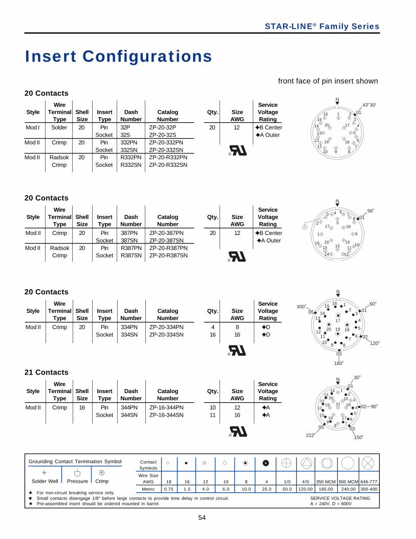
54
STAR-LINE® Family Series
Insert Configurationsfront face of pin insert shown
ContactSymbols
Wire SizeAWG 18 16 12 10 8 4 1/0 4/0 350 MCM 500 MCM 646-777
Metric 0.75 1.5 4.0 6.0 10.0 25.0 50.0 120.00 185.00 240.00 300-400
Grounding Contact Termination Symbol
Solder Well Pressure Crimp
✦ For non-circuit breaking service only.✱ Small contacts disengage 1/8” before large contacts to provide time delay in control circuit.★ Pre-assembled insert should be ordered mounted in barrel.
20 Contacts
Wire ServiceStyle Terminal Shell Insert Dash Catalog Qty. Size Voltage
Type Size Type Number Number AWG Rating
Mod II Crimp 20 Pin 387PN ZP-20-387PN 20 12 ✦ B CenterSocket 387SN ZP-20-387SN ✦ A Outer
Mod II Radsok 20 Pin R387PN ZP-20-R387PNCrimp Socket R387SN ZP-20-R387SN
®
20 Contacts
Wire ServiceStyle Terminal Shell Insert Dash Catalog Qty. Size Voltage
Type Size Type Number Number AWG Rating
Mod II Crimp 20 Pin 334PN ZP-20-334PN 4 8 ✦ DSocket 334SN ZP-20-334SN 16 16 ✦ D
®
21 Contacts
Wire ServiceStyle Terminal Shell Insert Dash Catalog Qty. Size Voltage
Type Size Type Number Number AWG Rating
Mod II Crimp 16 Pin 344PN ZP-16-344PN 10 12 ✦ ASocket 344SN ZP-16-344SN 11 16 ✦ A
Mod I Solder 20 Pin 32P ZP-20-32P 20 12 ✦ B CenterSocket 32S ZP-20-32S ✦ A Outer
Mod II Crimp 20 Pin 332PN ZP-20-332PNSocket 332SN ZP-20-332SN
Mod II Radsok 20 Pin R332PN ZP-20-R332PNCrimp Socket R332SN ZP-20-R332SN
20 ContactsWire Service
Style Terminal Shell Insert Dash Catalog Qty. Size VoltageType Size Type Number Number AWG Rating
®
®
N
1
2
3 4
5
67
8
9
1011
12
13
14
1516
17 18
1920
0156o
N
12
3
4
5
67
8910
1112
1314
1516
17
181920
0160o
02120o
03
180o
05300o
N
1 23
4
5
6
78910
11
12
13
14
1516
17
1819
20
01
43o 30'
N
12
3
45
678
9
10
11
12
1314
15
16
1718
19
20
21
01
30o
02 90o
03
150o
05
222o
SERVICE VOLTAGE RATINGA = 240V, D = 600V
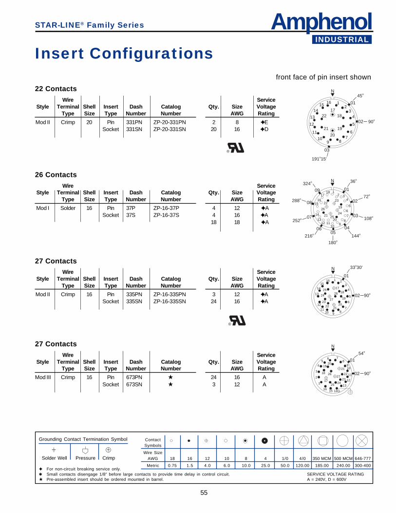
AmphenolINDUSTRIAL
55
STAR-LINE® Family Series
Insert Configurationsfront face of pin insert shown
ContactSymbols
Wire SizeAWG 18 16 12 10 8 4 1/0 4/0 350 MCM 500 MCM 646-777
Metric 0.75 1.5 4.0 6.0 10.0 25.0 50.0 120.00 185.00 240.00 300-400
Grounding Contact Termination Symbol
Solder Well Pressure Crimp
✦ For non-circuit breaking service only.✱ Small contacts disengage 1/8” before large contacts to provide time delay in control circuit.★ Pre-assembled insert should be ordered mounted in barrel.
27 ContactsWire Service
Style Terminal Shell Insert Dash Catalog Qty. Size VoltageType Size Type Number Number AWG Rating
Mod II Crimp 16 Pin 335PN ZP-16-335PN 3 12 ✦ ASocket 335SN ZP-16-335SN 24 16 ✦ A
27 ContactsWire Service
Style Terminal Shell Insert Dash Catalog Qty. Size VoltageType Size Type Number Number AWG Rating
Mod III Crimp 16 Pin 673PN ★ 24 16 ASocket 673SN ★ 3 12 A
®
Mod I Solder 16 Pin 37P ZP-16-37P 4 12 ✦ ASocket 37S ZP-16-37S 4 16 ✦ A
18 18 ✦ A
26 ContactsWire Service
Style Terminal Shell Insert Dash Catalog Qty. Size VoltageType Size Type Number Number AWG Rating
22 ContactsWire Service
Style Terminal Shell Insert Dash Catalog Qty. Size VoltageType Size Type Number Number AWG Rating
Mod II Crimp 20 Pin 331PN ZP-20-331PN 2 8 ✦ ESocket 331SN ZP-20-331SN 20 16 ✦ D
®
N
12
34
5
67
8910
11
12
13
1415 16
1718
19
20
21
22
01
45o
02 90o
03
191o15'
N
12 3
4
56
78
910
111213
14
1516
1718
19
2021
2223
2425
26
01
36o
0272o
03108o
04
144o05
180o
06
216o
07252o
08288o
09
324o
N
1 23
4
5
6
78
91011
12
13
1415
16
1718
19
202122
23
24
2526
2702 90o
01
33o30'
N
1
2
3
45
6 78
910
11
12
13
14G1516
17
18
1920
21
22
232425
2627
01
54o
02 90o
SERVICE VOLTAGE RATINGA = 240V, D = 600V
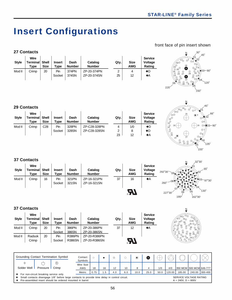
56
STAR-LINE® Family Series
Insert Configurationsfront face of pin insert shown
ContactSymbols
Wire SizeAWG 18 16 12 10 8 4 1/0 4/0 350 MCM 500 MCM 646-777
Metric 0.75 1.5 4.0 6.0 10.0 25.0 50.0 120.00 185.00 240.00 300-400
Grounding Contact Termination Symbol
Solder Well Pressure Crimp
✦ For non-circuit breaking service only.✱ Small contacts disengage 1/8” before large contacts to provide time delay in control circuit.★ Pre-assembled insert should be ordered mounted in barrel.
37 ContactsWire Service
Style Terminal Shell Insert Dash Catalog Qty. Size VoltageType Size Type Number Number AWG Rating
Mod II Crimp 20 Pin 386PN ZP-20-386PN 37 12 ✦ ASocket 386SN ZP-20-386SN
Mod II Radsok 20 Pin R386PN ZP-20-R386PNCrimp Socket R386SN ZP-20-R386SN
®
®
29 ContactsWire Service
Style Terminal Shell Insert Dash Catalog Qty. Size VoltageType Size Type Number Number AWG Rating
Mod II Crimp C28 Pin 328PN ZP-C28-328PN 4 1/0 ✦ DSocket 328SN ZP-C28-328SN 2 8 ✦ D
23 12 ✦ A
37 ContactsWire Service
Style Terminal Shell Insert Dash Catalog Qty. Size VoltageType Size Type Number Number AWG Rating
Mod II Crimp 16 Pin 321PN ZP-16-321PN 37 16 ✦ ASocket 321SN ZP-16-321SN
27 ContactsWire Service
Style Terminal Shell Insert Dash Catalog Qty. Size VoltageType Size Type Number Number AWG Rating
Mod II Crimp 20 Pin 374PN ZP-20-374PN 2 4 ✦ DSocket 374SN ZP-20-374SN 25 12 ✦ A
N
12
3
4
56
7
8910
1112
13
14
15
1617
18
19
20
212223
24
25
2627
01
30o
02
45o
03 90o
04120o
05
150o
06
225o
N
12
3
4
5
6
7
8
9
1011
121314
15
16
17
18
19
20
21
2223
24
25
26
27
28
0145o
0266o
03 90o
04135o
05
155o
N
12
34
5
6
78
91011
1213
14
15
1617 18
19
2021
2223
242526
2728
2930
3132
33
3435
3637
01
32o30'
0265o
03 97o30'
04130o
05
162o30'195º
0607
227o30'
260o 08
09292o30'
N
1234
5
6
7
8
910 11
12
13
14
15
16
17181920
21
22
23
24
2526
27
28
29303132
33
3435
3637
SERVICE VOLTAGE RATINGA = 240V, D = 600V
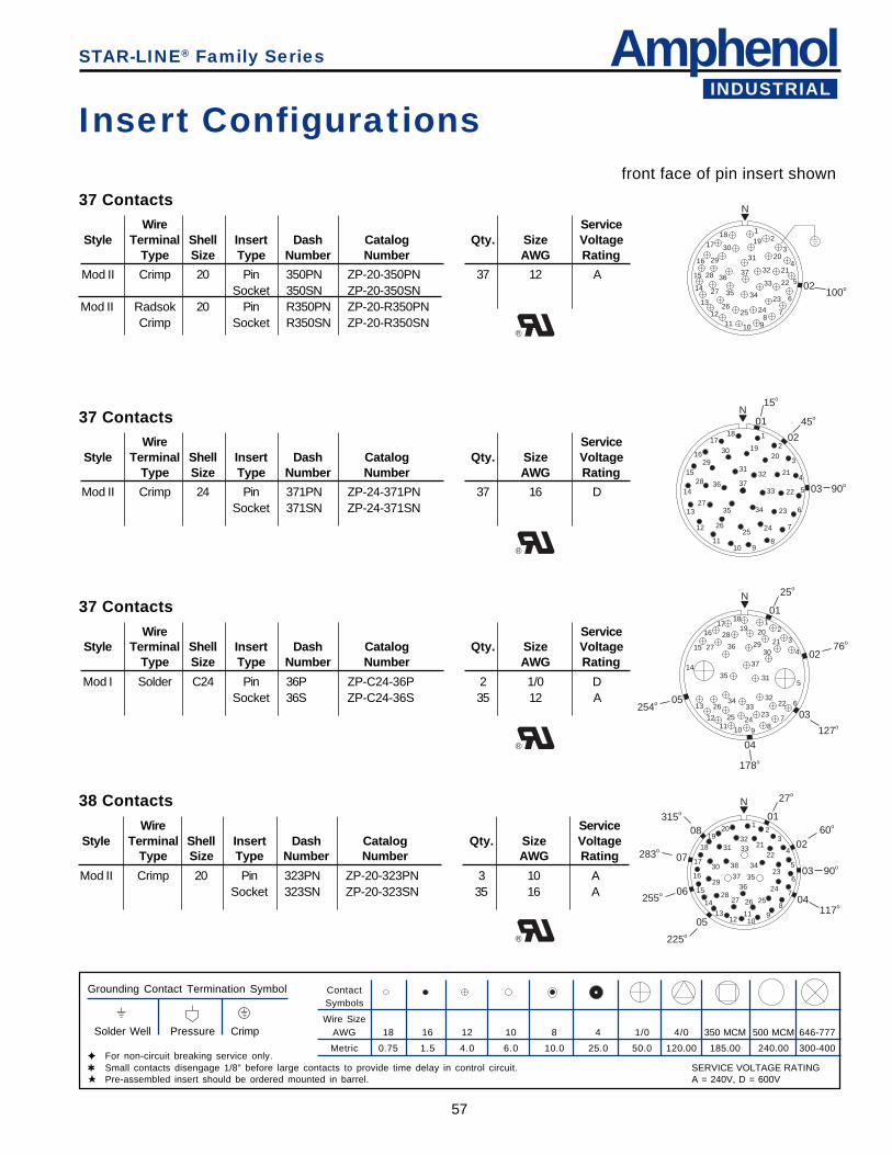
AmphenolINDUSTRIAL
57
STAR-LINE® Family Series
Insert Configurationsfront face of pin insert shown
ContactSymbols
Wire SizeAWG 18 16 12 10 8 4 1/0 4/0 350 MCM 500 MCM 646-777
Metric 0.75 1.5 4.0 6.0 10.0 25.0 50.0 120.00 185.00 240.00 300-400
Grounding Contact Termination Symbol
Solder Well Pressure Crimp
✦ For non-circuit breaking service only.✱ Small contacts disengage 1/8” before large contacts to provide time delay in control circuit.★ Pre-assembled insert should be ordered mounted in barrel.
38 ContactsWire Service
Style Terminal Shell Insert Dash Catalog Qty. Size VoltageType Size Type Number Number AWG Rating
Mod II Crimp 20 Pin 323PN ZP-20-323PN 3 10 ASocket 323SN ZP-20-323SN 35 16 A
®
37 ContactsWire Service
Style Terminal Shell Insert Dash Catalog Qty. Size VoltageType Size Type Number Number AWG Rating
Mod II Crimp 20 Pin 350PN ZP-20-350PN 37 12 ASocket 350SN ZP-20-350SN
Mod II Radsok 20 Pin R350PN ZP-20-R350PNCrimp Socket R350SN ZP-20-R350SN
®
37 ContactsWire Service
Style Terminal Shell Insert Dash Catalog Qty. Size VoltageType Size Type Number Number AWG Rating
Mod II Crimp 24 Pin 371PN ZP-24-371PN 37 16 DSocket 371SN ZP-24-371SN
®
37 ContactsWire Service
Style Terminal Shell Insert Dash Catalog Qty. Size VoltageType Size Type Number Number AWG Rating
Mod I Solder C24 Pin 36P ZP-C24-36P 2 1/0 DSocket 36S ZP-C24-36S 35 12 A
N
12
3
4
5
6
78
9101112
13
14
15
16
1718
19
20
21
22 02100o
23
242526
27
28
29
3031
32
33
3435
3637
N
12
3
4
5
6
7
8910
11
12
13
14
15
16
1718
1920
21
22
23
2425
26
27
28
29
30
3132
33
3435
36 37
01
02
03 90o
45o
15o
N
12
3
4
5
6
78
9101112
13
14
15
1617
1819 20
21
22
232425
26
27
2829
30
31
3233
34
35
36
37
01
25o
0276o
03
127o
04
05254o
178o
N
12
3
4
5
6
7
89
1011
1213
14
15
16
17
18
1920
2122
23
24
25262728
29
30
313233
34
3536
37
38
01
27o
0260o
90o03
04117o
05
225o
255o 06
07283o
08315o
SERVICE VOLTAGE RATINGA = 240V, D = 600V
®
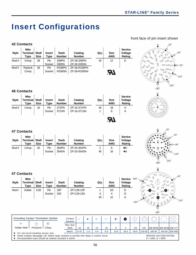
58
N
12
3
4
5
6
7
8
910
111213
14
15
16
17
18
1920
21 2223
24
25
26
27
282930
31
32
33
3435
36
37
3839
40
41 42
01
30o
0260o
03 90o
04120o
05
150o06
180o
STAR-LINE® Family Series
Insert Configurationsfront face of pin insert shown
ContactSymbols
Wire SizeAWG 18 16 12 10 8 4 1/0 4/0 350 MCM 500 MCM 646-777
Metric 0.75 1.5 4.0 6.0 10.0 25.0 50.0 120.00 185.00 240.00 300-400
Grounding Contact Termination Symbol
Solder Well Pressure Crimp
✦ For non-circuit breaking service only.✱ Small contacts disengage 1/8” before large contacts to provide time delay in control circuit.★ Pre-assembled insert should be ordered mounted in barrel.
47 ContactsWire Service
Style Terminal Shell Insert Dash Catalog Qty. Size VoltageType Size Type Number Number AWG Rating
Mod I Solder C28 Pin 15P ZP-C28-15P 1 1/0 DSocket 15S ZP-C28-15S 3 4 D
43 12 A
42 ContactsWire Service
Style Terminal Shell Insert Dash Catalog Qty. Size VoltageType Size Type Number Number AWG Rating
Mod II Crimp 28 Pin 339PN ZP-28-339PN 42 12 DSocket 339SN ZP-28-339SN
Mod II Radsok 28 Pin R339PN ZP-28-R339PNCrimp Socket R339SN ZP-28-R339SN
46 ContactsWire Service
Style Terminal Shell Insert Dash Catalog Qty. Size VoltageType Size Type Number Number AWG Rating
Mod II Crimp 16 Pin 371PN ZP-16-371PN 45 18 ASocket 371SN ZP-16-371SN 1 8 A
®
47 ContactsWire Service
Style Terminal Shell Insert Dash Catalog Qty. Size VoltageType Size Type Number Number AWG Rating
Mod II Crimp 20 Pin 354PN ZP-20-354PN 2 8 ✦ DSocket 354SN ZP-20-354SN 45 16 ✦ A
®
N
12
3
4
5
6
7
89
101112
1314
15
16
17
18
1920
2122 23
2425
26
27
28
2930
313233
34
35
36
37
38
3940
41
42
43
44
45
46
1 23
4
5
6
7
8
9
1011121314
1516
17
18
19
20
21
22
2324
25 2627
28
29
30
31
323334
3536
37
38
39
40
41
4243
44
45
46
47
N
01
30o
0260o
03 90o
04120o
05
150o06
180o
03
12
3
45
6
7
8
9
1011
12131415
16
17
18
19
20
21
22
23 24
25
2627
28
29
30
31
3233
34
35
36
37
38
3940
41
42 43
44
45
46
47
N
0160o
02120o
180o
04240o
05300o
SERVICE VOLTAGE RATINGA = 240V, D = 600V
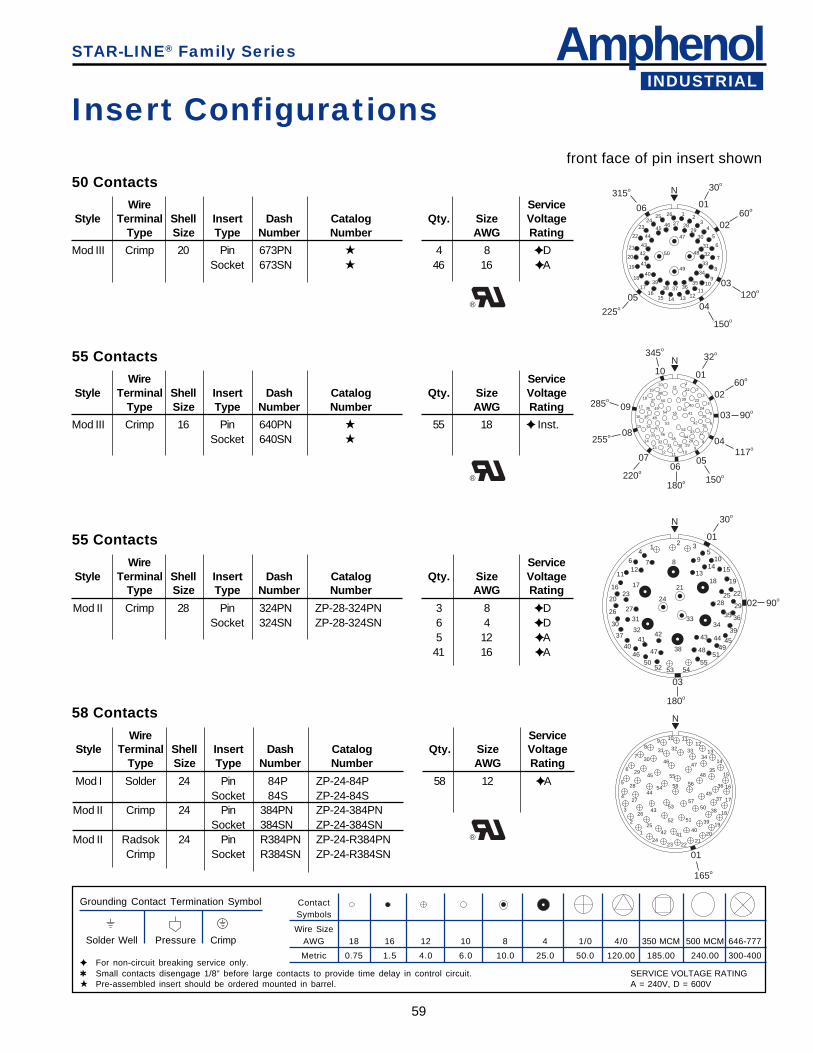
AmphenolINDUSTRIAL
59
N
1
2
3
4
5
6
7
89 10 11
12
13
14
15
16
17
18
19
2021
222324
25
26
27
28
29
30
31 32 3334
35
36
37
38
39
404142
43
44
45
4647
48
49
50
5152
53
54
55
56
57
58
01
165o
12
34
5
6
7
8
910
1112131415
1617
18
19
20
21
22
2324
25 26
27 2829
30
31
32
33
34
35363738
39
40
41
42
43
44
4546
47
48
49
50
N
01
30o
0260o
03120o
04
150o
05
225o
06
315o
STAR-LINE® Family Series
Insert Configurationsfront face of pin insert shown
ContactSymbols
Wire SizeAWG 18 16 12 10 8 4 1/0 4/0 350 MCM 500 MCM 646-777
Metric 0.75 1.5 4.0 6.0 10.0 25.0 50.0 120.00 185.00 240.00 300-400
Grounding Contact Termination Symbol
Solder Well Pressure Crimp
✦ For non-circuit breaking service only.✱ Small contacts disengage 1/8” before large contacts to provide time delay in control circuit.★ Pre-assembled insert should be ordered mounted in barrel.
Mod II Crimp 28 Pin 324PN ZP-28-324PN 3 8 ✦ DSocket 324SN ZP-28-324SN 6 4 ✦ D
5 12 ✦ A41 16 ✦ A
58 ContactsWire Service
Style Terminal Shell Insert Dash Catalog Qty. Size VoltageType Size Type Number Number AWG Rating
Mod I Solder 24 Pin 84P ZP-24-84P 58 12 ✦ ASocket 84S ZP-24-84S
Mod II Crimp 24 Pin 384PN ZP-24-384PNSocket 384SN ZP-24-384SN
Mod II Radsok 24 Pin R384PN ZP-24-R384PNCrimp Socket R384SN ZP-24-R384SN
50 ContactsWire Service
Style Terminal Shell Insert Dash Catalog Qty. Size VoltageType Size Type Number Number AWG Rating
Mod III Crimp 20 Pin 673PN ★ 4 8 ✦ DSocket 673SN ★ 46 16 ✦ A
®
55 ContactsWire Service
Style Terminal Shell Insert Dash Catalog Qty. Size VoltageType Size Type Number Number AWG Rating
Mod III Crimp 16 Pin 640PN ★ 55 18 ✦ Inst.Socket 640SN ★
®
55 ContactsWire Service
Style Terminal Shell Insert Dash Catalog Qty. Size VoltageType Size Type Number Number AWG Rating
1
2
3
4
5
6
7
8
9101112
13
14
15
16
17
18
1920
2122
23
24
25
26
27
28293031
32
33
34
35
36
37
38
39
40
41
42
434445
46
47
48
49
50
51
52
53
54 55
N10
345o
01
32o
0260o
03 90o
04117o
05
150o
06
180o
07
220o
08255o
09285o
N
12 3
4 56 7 8 9 10
1112 13
14 15
16 1718 19
20
212223
24 25
26 2728 29
3031
32
3334
35 36
37
38
39
4041
42 43 44 45
46 47 48 49
5051
52 53 5455
01
30o
90o02
03
180o
SERVICE VOLTAGE RATINGA = 240V, D = 600V
®
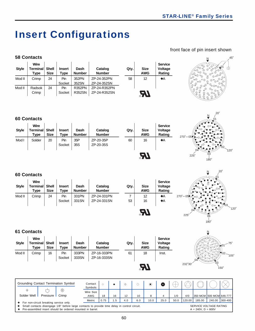
60
STAR-LINE® Family Series
Insert Configurationsfront face of pin insert shown
ContactSymbols
Wire SizeAWG 18 16 12 10 8 4 1/0 4/0 350 MCM 500 MCM 646-777
Metric 0.75 1.5 4.0 6.0 10.0 25.0 50.0 120.00 185.00 240.00 300-400
Grounding Contact Termination Symbol
Solder Well Pressure Crimp
✦ For non-circuit breaking service only.✱ Small contacts disengage 1/8” before large contacts to provide time delay in control circuit.★ Pre-assembled insert should be ordered mounted in barrel.
61 ContactsWire Service
Style Terminal Shell Insert Dash Catalog Qty. Size VoltageType Size Type Number Number AWG Rating
Mod II Crimp 16 Pin 333PN ZP-16-333PN 61 18 Inst.Socket 333SN ZP-16-333SN
®
58 ContactsWire Service
Style Terminal Shell Insert Dash Catalog Qty. Size VoltageType Size Type Number Number AWG Rating
Mod II Crimp 24 Pin 352PN ZP-24-352PN 58 12 ✦ ASocket 352SN ZP-24-352SN
Mod II Radsok 24 Pin R352PN ZP-24-R352PNCrimp Socket R352SN ZP-24-R352SN
60 ContactsWire Service
Style Terminal Shell Insert Dash Catalog Qty. Size VoltageType Size Type Number Number AWG Rating
Mod I Solder 20 Pin 35P ZP-20-35P 60 16 ✦ ASocket 35S ZP-20-35S
®
60 ContactsWire Service
Style Terminal Shell Insert Dash Catalog Qty. Size VoltageType Size Type Number Number AWG Rating
Mod II Crimp 24 Pin 331PN ZP-24-331PN 7 12 ✦ ASocket 331SN ZP-24-331SN 53 16 ✦ A
®
N
1 23
4
5
6
7
8
9
10
11
12131415
1617
18
19
20
20o
01
02120o
03
180o
04
225o
05270o 21
22
23
24
2526
27
2829
30
31
32
33
3435
36
37
38
39
40
41
42
43
44
45
464748
49
50
51
52
53
54
55
5657
58
59
60
N
1 23
4
5
6
7
8
9
10
11
1213141516
17
18
19
20
21
22
23
24
25
2627
2829
30
31
32
33
34
3536
37
38
39
40
41
42
4344
45
46
474849
50
51
5253
54
55
5657
58
5960
20o
03120o
06
180o
04
225o
05270o
01
N
12
3
4
5
6
7
8
910
11121314
15
16
17
18
19
20
2122
23 24
2526
27
28
29
30
31
3233
343536
37
38
39
40
4142
4344
45
46
47
484950
51
52
53
54 01
02105o
03
150o
04232o30'
75o
5556
57
5859
60 61
N
1 23
4
5
6
7
8
9
1011
12131415
16
17
18
19
20
21
22
2324
25 2627
28
29
30
31
32
333435
36
37
38
39
40
41
42
43
44
45
45o
01
46
4748
49
50
51
52
53
54
5556
57
58
SERVICE VOLTAGE RATINGA = 240V, D = 600V
®
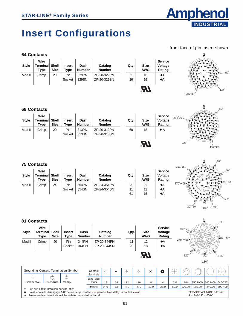
AmphenolINDUSTRIAL
61
N
12
3
4
5
6
7
8
9
1011
12131415
16
17
18
19
20
21
22
23
2425 26
2728
2930
31
32
33
34
35
363738
39
40
41
42
43
44
45
46
4748
49
50
51
5253
54
01 90o
02
135o03
202o30'
55
56
57
58
59
60
61
62
63
64
STAR-LINE® Family Series
Insert Configurationsfront face of pin insert shown
ContactSymbols
Wire SizeAWG 18 16 12 10 8 4 1/0 4/0 350 MCM 500 MCM 646-777
Metric 0.75 1.5 4.0 6.0 10.0 25.0 50.0 120.00 185.00 240.00 300-400
Grounding Contact Termination Symbol
Solder Well Pressure Crimp
✦ For non-circuit breaking service only.✱ Small contacts disengage 1/8” before large contacts to provide time delay in control circuit.★ Pre-assembled insert should be ordered mounted in barrel.
81 ContactsWire Service
Style Terminal Shell Insert Dash Catalog Qty. Size VoltageType Size Type Number Number AWG Rating
Mod II Crimp 20 Pin 344PN ZP-20-344PN 11 12 ✦ ASocket 344SN ZP-20-344SN 70 18 ✦ A
®
Mod II Crimp 24 Pin 354PN ZP-24-354PN 3 8 ✦ ASocket 354SN ZP-24-354SN 11 12 ✦ A
61 16 ✦ A
64 ContactsWire Service
Style Terminal Shell Insert Dash Catalog Qty. Size VoltageType Size Type Number Number AWG Rating
Mod II Crimp 20 Pin 329PN ZP-20-329PN 2 10 ✦ ASocket 329SN ZP-20-329SN 16 16 ✦ A
®
68 ContactsWire Service
Style Terminal Shell Insert Dash Catalog Qty. Size VoltageType Size Type Number Number AWG Rating
Mod II Crimp 20 Pin 313PN ZP-20-313PN 68 18 ✦ ASocket 313SN ZP-20-313SN
®
75 ContactsWire Service
Style Terminal Shell Insert Dash Catalog Qty. Size VoltageType Size Type Number Number AWG Rating
N
12
3
4
5
6
7
8
9
1011
12131415
16
17
18
19
20
21
22
2324
25 26
2728
29
30
31
32
33
3435
363738
3940
41
42
43
4445
46
4748
49
50
51
525354
02
45o
03
157o30'
04
228o
05292o30'
5556
57
58
5960
6162
63
6465
66
6768
N
1 23
45
6
7
8
9
10
11
1213
14151617
1819
20
21
22
23
24
25
26
27
2829
30 31
3233
3435
36
37
38
39
40
4142
43444546
47
48
49
50
51
52
53
54
01
30o
0260o
03 90º
04127o
05
160º
06
180o
07
207o30'
08
09311o15'
270o
55
56
57
58
59
60
61
6263
64
65
66
67
6869
70
71
7273
74
75
N
1
2
3
4
5
6
7
89
1011
12
13
14
15
16
17
18
19
20 21
2223
24
25
26
27
28
29
3031
32333435
3637
38
39
40
41
42
4344
4546 47
48
49
50
51
52
53
54
01
45o
02 90o
03135o
04
180o
05
225o
06270o
07300o
555657
58
59
60
61
6263
6465
66
67
6869
7071
72
73
74
7576
77
7879
80
81
SERVICE VOLTAGE RATINGA = 240V, D = 600V
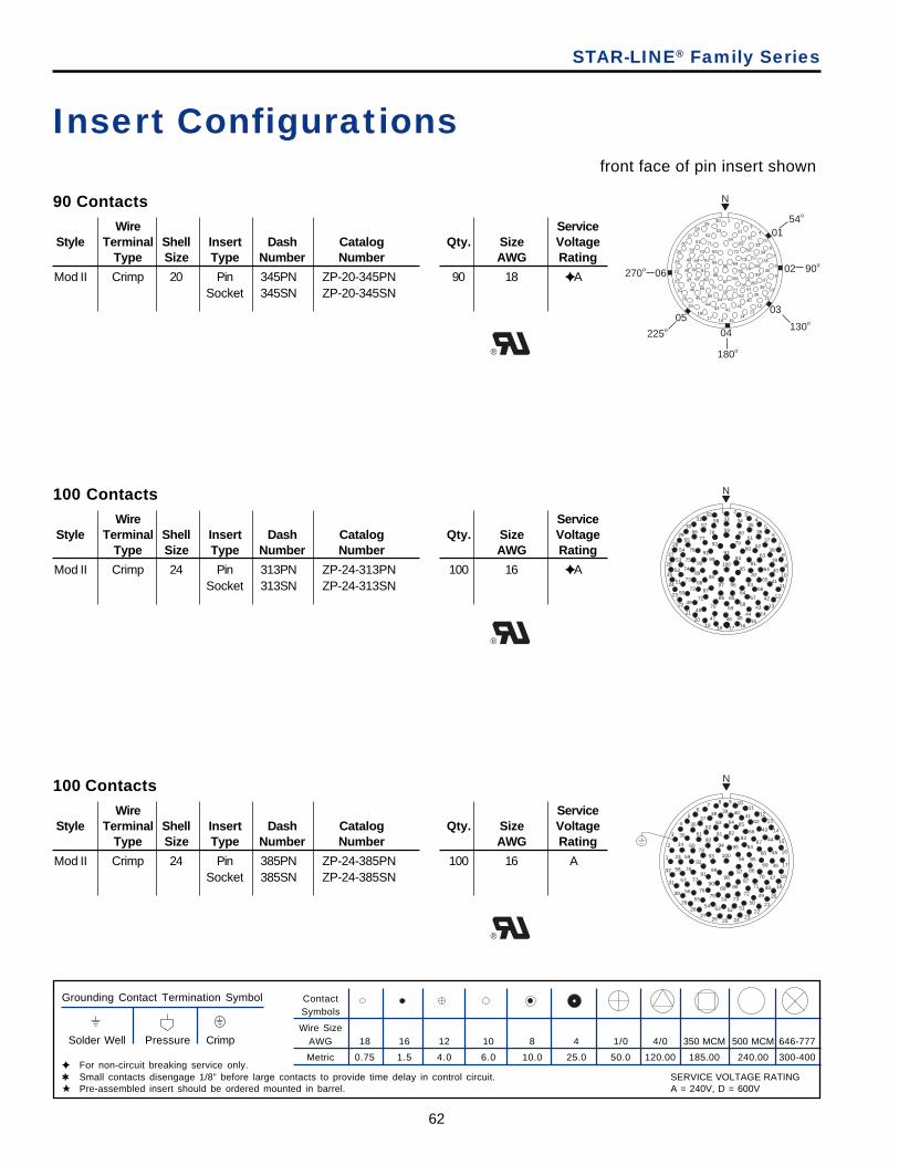
62
STAR-LINE® Family Series
Insert Configurationsfront face of pin insert shown
ContactSymbols
Wire SizeAWG 18 16 12 10 8 4 1/0 4/0 350 MCM 500 MCM 646-777
Metric 0.75 1.5 4.0 6.0 10.0 25.0 50.0 120.00 185.00 240.00 300-400
Grounding Contact Termination Symbol
Solder Well Pressure Crimp
✦ For non-circuit breaking service only.✱ Small contacts disengage 1/8” before large contacts to provide time delay in control circuit.★ Pre-assembled insert should be ordered mounted in barrel.
100 ContactsWire Service
Style Terminal Shell Insert Dash Catalog Qty. Size VoltageType Size Type Number Number AWG Rating
Mod II Crimp 24 Pin 385PN ZP-24-385PN 100 16 ASocket 385SN ZP-24-385SN
®
90 ContactsWire Service
Style Terminal Shell Insert Dash Catalog Qty. Size VoltageType Size Type Number Number AWG Rating
Mod II Crimp 20 Pin 345PN ZP-20-345PN 90 18 ✦ ASocket 345SN ZP-20-345SN
®
100 ContactsWire Service
Style Terminal Shell Insert Dash Catalog Qty. Size VoltageType Size Type Number Number AWG Rating
Mod II Crimp 24 Pin 313PN ZP-24-313PN 100 16 ✦ ASocket 313SN ZP-24-313SN
®
N
1 23
4
5
6
7
8
9
10
11
1213
14151617
18
19
20
21
22
23
24
25
26
27
2829
30
3132
33
34
35
36
37
38
3940
414243
4445
46
47
48
49
50
51
5253
54
54o
01
90o02
03
130o
04
180o
05
225o
270o 06
55
56
57
58
59
6061
626364
65
66
67
68
69
70
71
72
73
74
75
767778
79
80
81
82
83
84
85
8687
88
8990
1
2
3
4
56
78 9 10
1112
13
14
15
16
17
18
19
20
2122
2324252627
2829
30
31
32
33
34
35
3637
38 39 4041
42
43
44
45
46
47
48
4950
5152535455
56
57
58
59
60
6162
63 64 6566
67
68
69
70
71
727374
7576
77
78
79
8081 82
83
84
85
86
878889
90
91
9293
94 95
96
9798
99
100
N
N
1 2 34
5
6
7
8
9
10
11
12
13
1415
1617181920
21
22
23
24
25
26
27
28
29
3031
3233 34
3536
37
38
39
40
41
42
4344
454647
48
49
50
51
52
53
54
55
5657
58
59 6061
62
63
64
65
66
6768
6970
71
72
73
74
75
76
7778
7980
81
82
83
848586
87
88
89
90
91
92
9394
95
9697
98
99100
SERVICE VOLTAGE RATINGA = 240V, D = 600V

AmphenolINDUSTRIAL
63
1 23
4
5
6
7
8
9
10
11
12
1314
151617
18
19
20
21
22
23
24
25
26
27
2829 30
3132
33
34
35
36
37
38
39
40
4142
43444546
47
48
49
50
51
52
53
54
5556 57
5859
60
61
62
63
64
65
6667
686970
71
72
73
74
75
76
7778
7980
81
82
83
84
858687
88
89
90
91
9293
94
95
9697
98
99100
N
60o
01
100 ContactsWire Service
Style Terminal Shell Insert Dash Catalog Qty. Size VoltageType Size Type Number Number AWG Rating
Mod II Crimp 28 Pin 314PN ZP-28-314PN 17 12 ✦ ASocket 314SN ZP-28-314SN 83 16 ✦ A
®
143 ContactsWire Service
Style Terminal Shell Insert Dash Catalog Qty. Size VoltageType Size Type Number Number AWG Rating
Mod II Crimp 28 Pin 322PN ZP-28-322PN 143 16 ✦ ASocket 322SN ZP-28-322SN
®
STAR-LINE® Family Series
Insert Configurationsfront face of pin insert shown
ContactSymbols
Wire SizeAWG 18 16 12 10 8 4 1/0 4/0 350 MCM 500 MCM 646-777
Metric 0.75 1.5 4.0 6.0 10.0 25.0 50.0 120.00 185.00 240.00 300-400
Grounding Contact Termination Symbol
Solder Well Pressure Crimp
✦ For non-circuit breaking service only.✱ Small contacts disengage 1/8” before large contacts to provide time delay in control circuit.★ Pre-assembled insert should be ordered mounted in barrel.
12
34
56
7
8
9
10
11
12
13
14
1516
171819202122
2324
25
26
27
28
29
30
31
32
33
34
3536
3738 39
4041
4243
44
45
46
47
48
49
50
51
5253
54555657
5859
60
61
62
63
64
65
66
67
6869
7071 72
7374
7576
77
78
79
80
81
82
8384
85868788
89
90
91
92
93
94
95
9697
98 99
100101
102
103
104
105
106
107108
109110111112
113
114
115
116
117
118119
120
121
122
123
124
125
126127
128
129
130
131
132
133 134
135
136
137
138139
140
141
142
143
N
0146o30'
SERVICE VOLTAGE RATINGA = 240V, D = 600V
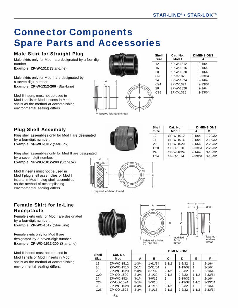
64
Connector ComponentsSpare Parts and AccessoriesMale Skirt for Straight PlugMale skirts only for Mod I are designated by a four-digitnumber.Example: ZP-W-1312 (Star-Line)
Male skirts only for Mod II are designated bya seven-digit number.Example: ZP-W-1312-200 (Star-Line)
Mod II inserts must not be used inMod I shells or Mod I inserts in Mod IIshells as the method of accomplishingenvironmental sealing differs
Female Skirt for In-LineReceptacleFemale skirts only for Mod I are designatedby a four-digit number.Example: ZP-WO-1512 (Star-Line)
Female skirts only for Mod II aredesignated by a seven-digit number.Example: ZP-WO-1512-200 (Star-Line)
Mod II inserts must not be used inMod I shells or Mod I inserts in Mod IIshells as the method of accomplishingenvironmental sealing differs.
STAR-LINE® • STAR-LOKTM
Plug Shell AssemblyPlug shell assemblies only for Mod I are designatedby a four-digit number.Example: SP-WO-1012 (Star-Lok)
Plug shell assemblies only for Mod II are designatedby a seven-digit number.Example: SP-WO-1012-200 (Star-Lok)
Mod II inserts must not be used inMod I plug shell assemblies or Mod Iinserts in Mod II plug shell assembliesas the method of accomplishingenvironmental sealing differs
A
B
Tapered left-hand thread
A
Tapered left-hand thread
Shell Cat. No. DIMENSIONSSize Mod I A
12 ZP-W-1312 2-1/6416 ZP-W-1316 2-1/6420 ZP-W-1320 2-1/64C20 ZP-C-1320 2-33/6424 ZP-W-1324 2-1/64C24 ZP-C-1324 2-33/6428 ZP-W-1328 2-1/64C28 ZP-C-1328 2-33/64
Shell Cat. No. DIMENSIONSSize Mod I A B
12 SP-W-1012 2-1/64 1-29/3216 SP-W-1016 2-1/64 2-13/3220 SP-W-1020 2-1/64 2-29/32C20 SP-C-1020 2-33/64 2-29/3224 SP-W-1024 2-1/64 3-13/32C24 SP-C-1024 2-33/64 3-13/32
DIMENSIONSShell Cat. No.Size Mod I A B C D E F
A
B
Safety wire holes(3) .062 Dia.
FE
C D
ModifiedAcmethread
Taperedleft-hand thread
3/16
12 ZP-WO-1512 1-3/4 1-61/64 1-1/2 1-3/32 1 2-1/6416 ZP-WO-1516 2-1/4 2-31/64 2 1-19/32 1 2-1/6420 ZP-WO-1520 2-3/4 3-1/32 2-1/2 2-3/32 1 2-1/64C20 ZP-CO-1520 2-3/4 3-1/32 2-1/2 2-3/32 1-1/2 2-33/6424 ZP-WO-1524 3-1/4 3-9/16 3 2-19/32 1 2-1/64C24 ZP-CO-1524 3-1/4 3-9/16 3 2-19/32 1-1/2 2-33/6428 ZP-WO-1528 3-3/4 4-1/16 3-1/2 3-3/32 1 2-1/64C28 ZP-CO-1528 3-3/4 4-1/16 3-1/2 3-3/32 1-1/2 2-33/64
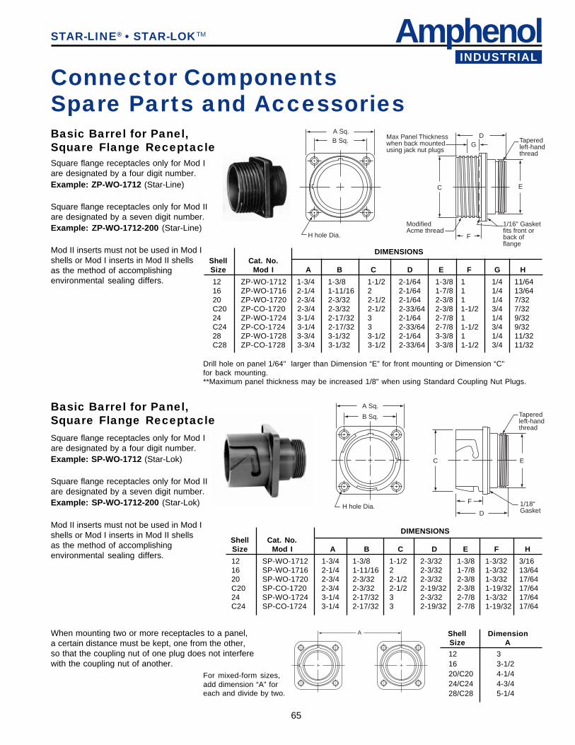
AmphenolINDUSTRIAL
65
A
Basic Barrel for Panel,Square Flange Receptacle
When mounting two or more receptacles to a panel,a certain distance must be kept, one from the other,so that the coupling nut of one plug does not interferewith the coupling nut of another.
Square flange receptacles only for Mod Iare designated by a four digit number.Example: ZP-WO-1712 (Star-Line)
Square flange receptacles only for Mod IIare designated by a seven digit number.Example: ZP-WO-1712-200 (Star-Line)
Mod II inserts must not be used in Mod Ishells or Mod I inserts in Mod II shellsas the method of accomplishingenvironmental sealing differs.
For mixed-form sizes,add dimension “A” foreach and divide by two.
Connector ComponentsSpare Parts and Accessories
STAR-LINE® • STAR-LOKTM
Basic Barrel for Panel,Square Flange ReceptacleSquare flange receptacles only for Mod Iare designated by a four digit number.Example: SP-WO-1712 (Star-Lok)
Square flange receptacles only for Mod IIare designated by a seven digit number.Example: SP-WO-1712-200 (Star-Lok)
Mod II inserts must not be used in Mod Ishells or Mod I inserts in Mod II shellsas the method of accomplishingenvironmental sealing differs.
Drill hole on panel 1/64" larger than Dimension “E” for front mounting or Dimension “C”for back mounting.**Maximum panel thickness may be increased 1/8" when using Standard Coupling Nut Plugs.
A Sq.B Sq.
DG
EC
ModifiedAcme thread
F
1/16" Gasketfits front orback offlange
Taperedleft-handthread
Max Panel Thicknesswhen back mountedusing jack nut plugs
H hole Dia.
H hole Dia.
A Sq.
B Sq.
C E
F
D1/18"Gasket
Taperedleft-handthread
DIMENSIONSShell Cat. No.Size Mod I A B C D E F G H
12 ZP-WO-1712 1-3/4 1-3/8 1-1/2 2-1/64 1-3/8 1 1/4 11/6416 ZP-WO-1716 2-1/4 1-11/16 2 2-1/64 1-7/8 1 1/4 13/6420 ZP-WO-1720 2-3/4 2-3/32 2-1/2 2-1/64 2-3/8 1 1/4 7/32C20 ZP-CO-1720 2-3/4 2-3/32 2-1/2 2-33/64 2-3/8 1-1/2 3/4 7/3224 ZP-WO-1724 3-1/4 2-17/32 3 2-1/64 2-7/8 1 1/4 9/32C24 ZP-CO-1724 3-1/4 2-17/32 3 2-33/64 2-7/8 1-1/2 3/4 9/3228 ZP-WO-1728 3-3/4 3-1/32 3-1/2 2-1/64 3-3/8 1 1/4 11/32C28 ZP-CO-1728 3-3/4 3-1/32 3-1/2 2-33/64 3-3/8 1-1/2 3/4 11/32
DIMENSIONSShell Cat. No.Size Mod I A B C D E F H
12 SP-WO-1712 1-3/4 1-3/8 1-1/2 2-3/32 1-3/8 1-3/32 3/1616 SP-WO-1716 2-1/4 1-11/16 2 2-3/32 1-7/8 1-3/32 13/6420 SP-WO-1720 2-3/4 2-3/32 2-1/2 2-3/32 2-3/8 1-3/32 17/64C20 SP-CO-1720 2-3/4 2-3/32 2-1/2 2-19/32 2-3/8 1-19/32 17/6424 SP-WO-1724 3-1/4 2-17/32 3 2-3/32 2-7/8 1-3/32 17/64C24 SP-CO-1724 3-1/4 2-17/32 3 2-19/32 2-7/8 1-19/32 17/64
Shell DimensionSize A
12 316 3-1/220/C20 4-1/424/C24 4-3/428/C28 5-1/4
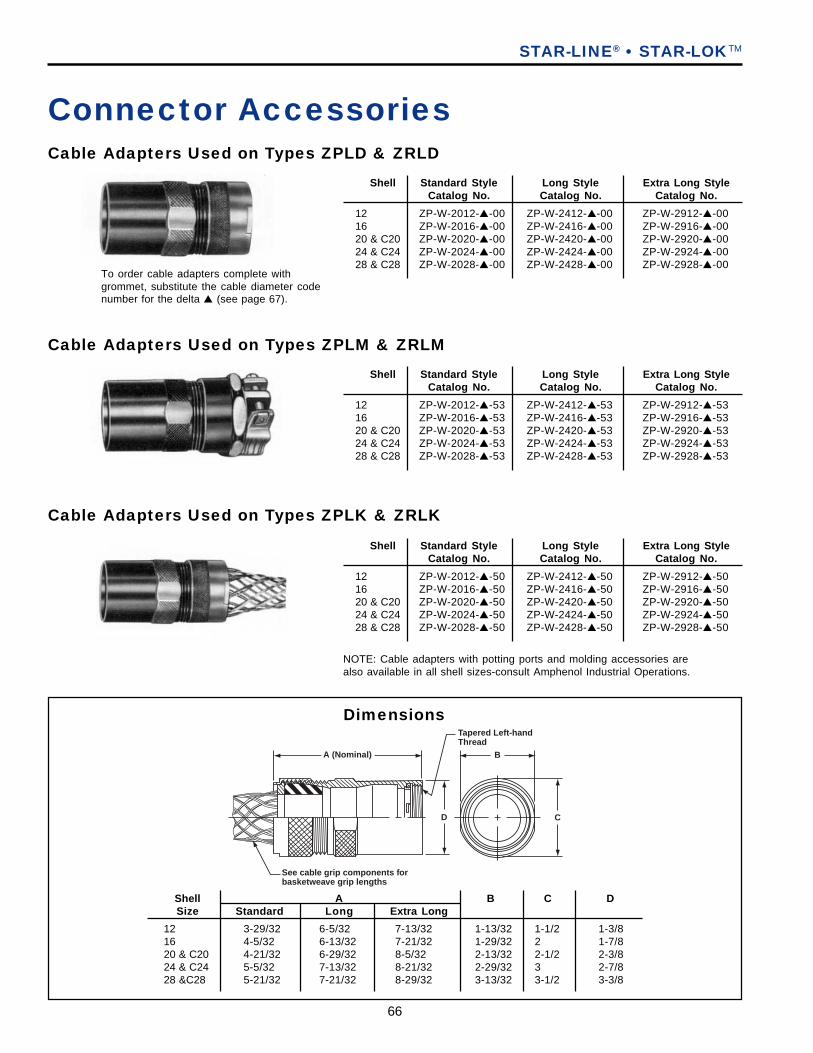
66
Tapered Left-handThread
BA (Nominal)
CD
See cable grip components forbasketweave grip lengths
Dimensions
Cable Adapters Used on Types ZPLD & ZRLD
Cable Adapters Used on Types ZPLM & ZRLM
Cable Adapters Used on Types ZPLK & ZRLK
NOTE: Cable adapters with potting ports and molding accessories arealso available in all shell sizes-consult Amphenol Industrial Operations.
To order cable adapters complete withgrommet, substitute the cable diameter codenumber for the delta ▲ (see page 67).
STAR-LINE® • STAR-LOKTM
Connector Accessories
Shell Standard Style Long Style Extra Long StyleCatalog No. Catalog No. Catalog No.
12 ZP-W-2012-▲-00 ZP-W-2412-▲-00 ZP-W-2912-▲-0016 ZP-W-2016-▲-00 ZP-W-2416-▲-00 ZP-W-2916-▲-0020 & C20 ZP-W-2020-▲-00 ZP-W-2420-▲-00 ZP-W-2920-▲-0024 & C24 ZP-W-2024-▲-00 ZP-W-2424-▲-00 ZP-W-2924-▲-0028 & C28 ZP-W-2028-▲-00 ZP-W-2428-▲-00 ZP-W-2928-▲-00
Shell Standard Style Long Style Extra Long StyleCatalog No. Catalog No. Catalog No.
12 ZP-W-2012-▲-53 ZP-W-2412-▲-53 ZP-W-2912-▲-5316 ZP-W-2016-▲-53 ZP-W-2416-▲-53 ZP-W-2916-▲-5320 & C20 ZP-W-2020-▲-53 ZP-W-2420-▲-53 ZP-W-2920-▲-5324 & C24 ZP-W-2024-▲-53 ZP-W-2424-▲-53 ZP-W-2924-▲-5328 & C28 ZP-W-2028-▲-53 ZP-W-2428-▲-53 ZP-W-2928-▲-53
Shell Standard Style Long Style Extra Long StyleCatalog No. Catalog No. Catalog No.
12 ZP-W-2012-▲-50 ZP-W-2412-▲-50 ZP-W-2912-▲-5016 ZP-W-2016-▲-50 ZP-W-2416-▲-50 ZP-W-2916-▲-5020 & C20 ZP-W-2020-▲-50 ZP-W-2420-▲-50 ZP-W-2920-▲-5024 & C24 ZP-W-2024-▲-50 ZP-W-2424-▲-50 ZP-W-2924-▲-5028 & C28 ZP-W-2028-▲-50 ZP-W-2428-▲-50 ZP-W-2928-▲-50
Shell A B C DSize Standard Long Extra Long
12 3-29/32 6-5/32 7-13/32 1-13/32 1-1/2 1-3/816 4-5/32 6-13/32 7-21/32 1-29/32 2 1-7/820 & C20 4-21/32 6-29/32 8-5/32 2-13/32 2-1/2 2-3/824 & C24 5-5/32 7-13/32 8-21/32 2-29/32 3 2-7/828 &C28 5-21/32 7-21/32 8-29/32 3-13/32 3-1/2 3-3/8
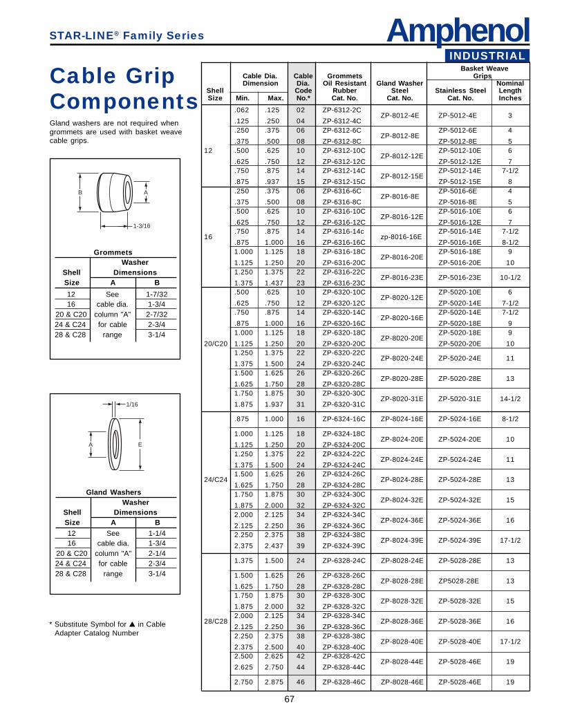
AmphenolINDUSTRIAL
67
Cable GripComponentsGland washers are not required whengrommets are used with basket weavecable grips.
STAR-LINE® Family Series
.062 .125 02 ZP-6312-2CZP-8012-4E ZP-5012-4E 3
.125 .250 04 ZP-6312-4C
.250 .375 06 ZP-6312-6C ZP-5012-6E 4ZP-8012-8E
.375 .500 08 ZP-6312-8C ZP-5012-8E 512 .500 .625 10 ZP-6312-10C ZP-5012-10E 6
ZP-8012-12E.625 .750 12 ZP-6312-12C ZP-5012-12E 7.750 .875 14 ZP-6312-14C ZP-5012-14E 7-1/2
ZP-8012-15E.875 .937 15 ZP-6312-15C ZP-5012-15E 8.250 .375 06 ZP-6316-6C ZP-5016-6E 4
ZP-8016-8E.375 .500 08 ZP-6316-8C ZP-5016-8E 5.500 .625 10 ZP-6316-10C ZP-5016-10E 6
ZP-8016-12E.625 .750 12 ZP-6316-12C ZP-5016-12E 7.750 .875 14 ZP-6316-14c ZP-5016-14E 7-1/2
16 zp-8016-16E.875 1.000 16 ZP-6316-16C ZP-5016-16E 8-1/21.000 1.125 18 ZP-6316-18C ZP-5016-18E 9
ZP-8016-20E1.125 1.250 20 ZP-6316-20C ZP-5016-20E 101.250 1.375 22 ZP-6316-22C
ZP-8016-23E ZP-5016-23E 10-1/21.375 1.437 23 ZP-6316-23C.500 .625 10 ZP-6320-10C ZP-5020-10E 6
ZP-8020-12E.625 .750 12 ZP-6320-12C ZP-5020-14E 7-1/2.750 .875 14 ZP-6320-14C ZP-5020-14E 7-1/2
ZP-8020-16E.875 1.000 16 ZP-6320-16C ZP-5020-18E 91.000 1.125 18 ZP-6320-18C ZP-5020-18E 9
ZP-8020-20E20/C20 1.125 1.250 20 ZP-6320-20C ZP-5020-20E 10
1.250 1.375 22 ZP-6320-22CZP-8020-24E ZP-5020-24E 11
1.375 1.500 24 ZP-6320-24C1.500 1.625 26 ZP-6320-26C
ZP-8020-28E ZP-5020-28E 131.625 1.750 28 ZP-6320-28C1.750 1.875 30 ZP-6320-30C
ZP-8020-31E ZP-5020-31E 14-1/21.875 1.937 31 ZP-6320-31C
.875 1.000 16 ZP-6324-16C ZP-8024-16E ZP-5024-16E 8-1/2
1.000 1.125 18 ZP-6324-18CZP-8024-20E ZP-5024-20E 10
1.125 1.250 20 ZP-6324-20C1.250 1.375 22 ZP-6324-22C
ZP-8024-24E ZP-5024-24E 111.375 1.500 24 ZP-6324-24C1.500 1.625 26 ZP-6324-26C
24/C24 ZP-8024-28E ZP-5024-28E 131.625 1.750 28 ZP-6324-28C1.750 1.875 30 ZP-6324-30C
ZP-8024-32E ZP-5024-32E 151.875 2.000 32 ZP-6324-32C2.000 2.125 34 ZP-6324-34C
ZP-8024-36E ZP-5024-36E 162.125 2.250 36 ZP-6324-36C2.250 2.375 38 ZP-6324-38C
ZP-8024-39E ZP-5024-39E 17-1/22.375 2.437 39 ZP-6324-39C
1.375 1.500 24 ZP-6328-24C ZP-8028-24E ZP-5028-28E 13
1.500 1.625 26 ZP-6328-26CZP-8028-28E ZP5028-28E 13
1.625 1.750 28 ZP-6328-28C1.750 1.875 30 ZP-6328-30C
ZP-8028-32E ZP-5028-32E 151.875 2.000 32 ZP-6328-32C2.000 2.125 34 ZP-6328-34C
28/C28 ZP-8028-36E ZP-5028-36E 162.125 2.250 36 ZP-6328-36C2.250 2.375 38 ZP-6328-38C
ZP-8028-40E ZP-5028-40E 17-1/22.375 2.500 40 ZP-6328-40C2.500 2.625 42 ZP-6328-42C
ZP-8028-44E ZP-5028-46E 192.625 2.750 44 ZP-6328-44C
2.750 2.875 46 ZP-6328-46C ZP-8028-46E ZP-5028-46E 19
Basket WeaveCable Dia. Cable Grommets GripsDimension Dia. Oil Resistant Gland Washer Nominal
Shell Code Rubber Steel Stainless Steel LengthSize Min. Max. No.* Cat. No. Cat. No. Cat. No. Inches
A
1/16
E
B A
1-3/16
GrommetsWasher
Shell DimensionsSize A B
12 See 1-7/3216 cable dia. 1-3/4
20 & C20 column "A" 2-7/3224 & C24 for cable 2-3/428 & C28 range 3-1/4
Gland WashersWasher
Shell DimensionsSize A B12 See 1-1/416 cable dia. 1-3/4
20 & C20 column "A" 2-1/424 & C24 for cable 2-3/428 & C28 range 3-1/4
* Substitute Symbol for ▲ in CableAdapter Catalog Number
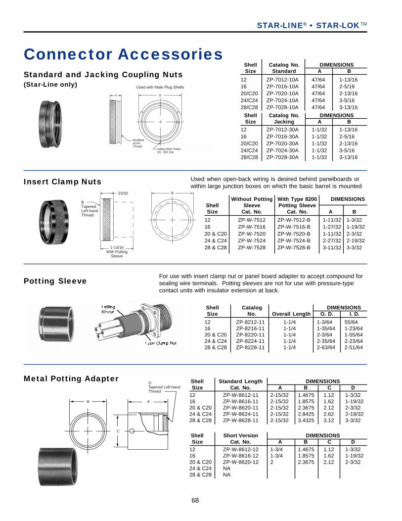
68
A
DTapered Left-handThread
C
B
23/32
BTaperedLeft-handThread
1-13/16With Potting
Sleeve
A
Standard and Jacking Coupling Nuts(Star-Line only)
Potting Sleeve
Insert Clamp Nuts Used when open-back wiring is desired behind panelboards orwithin large junction boxes on which the basic barrel is mounted
For use with insert clamp nut or panel board adapter to accept compound forsealing wire terminals. Potting sleeves are not for use with pressure-typecontact units with insulator extension at back.
STAR-LINE® • STAR-LOKTM
Connector AccessoriesShell Catalog No. DIMENSIONSSize Standard A B
Shell Catalog No. DIMENSIONSSize Jacking A B
12 ZP-7012-30A 1-1/32 1-13/1616 ZP-7016-30A 1-1/32 2-5/1620/C20 ZP-7020-30A 1-1/32 2-13/1624/C24 ZP-7024-30A 1-1/32 3-5/1628/C28 ZP-7028-30A 1-1/32 3-13/16
12 ZP-7012-10A 47/64 1-13/1616 ZP-7016-10A 47/64 2-5/1620/C20 ZP-7020-10A 47/64 2-13/1624/C24 ZP-7024-10A 47/64 3-5/1628/C28 ZP-7028-10A 47/64 3-13/16
Without Potting With Type 8200 DIMENSIONSShell Sleeve Potting SleeveSize Cat. No. Cat. No. A B
12 ZP-W-7512 ZP-W-7512-B 1-11/32 1-3/3216 ZP-W-7516 ZP-W-7516-B 1-27/32 1-19/3220 & C20 ZP-W-7520 ZP-W-7520-B 1-11/32 2-3/3224 & C24 ZP-W-7524 ZP-W-7524-B 2-27/32 2-19/3228 & C28 ZP-W-7528 ZP-W-7528-B 3-11/32 3-3/32
Shell Catalog DIMENSIONSSize No. Overall Length O. D. I. D.
12 ZP-8212-11 1-1/4 1-3/64 55/6416 ZP-8216-11 1-1/4 1-35/64 1-23/6420 & C20 ZP-8220-11 1-1/4 2-3/64 1-55/6424 & C24 ZP-8224-11 1-1/4 2-35/64 2-23/6428 & C28 ZP-8228-11 1-1/4 2-63/64 2-51/64
BA
Safety Wire Holes(3) .062 Dia.
ModifiedAcmeThread
Used with Male Plug Shells
Metal Potting Adapter Shell Standard Length DIMENSIONSSize Cat. No. A B C D
12 ZP-W-8612-11 2-15/32 1.4675 1.12 1-3/3216 ZP-W-8616-11 2-15/32 1.8575 1.62 1-19/3220 & C20 ZP-W-8620-11 2-15/32 2.3675 2.12 2-3/3224 & C24 ZP-W-8624-11 2-15/32 2.8425 2.62 2-19/3228 & C28 ZP-W-8628-11 2-15/32 3.4325 3.12 3-3/32
Shell Short Version DIMENSIONSSize Cat. No. A B C D
12 ZP-W-8612-12 1-3/4 1.4675 1.12 1-3/3216 ZP-W-8616-12 1-3/4 1.8575 1.62 1-19/3220 & C20 ZP-W-8620-12 2 2.3675 2.12 2-3/3224 & C24 NA28 & C28 NA
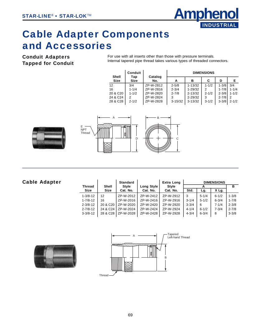
AmphenolINDUSTRIAL
69
A
Thread
TaperedLeft-hand Thread
B
Cable Adapter Componentsand Accessories
STAR-LINE® • STAR-LOKTM
Conduit AdaptersTapped for Conduit
For use with all inserts other than those with pressure terminals.Internal tapered pipe thread takes various types of threaded connectors.
A
ENPTThread
D
B
C
Conduit DIMENSIONSShell Tap CatalogSize Size No. A B C D E
12 3/4 ZP-W-2812 2-5/8 1-13/32 1-1/2 1-3/8 3/416 1-1/4 ZP-W-2816 2-3/4 1-29/32 2 1-7/8 1-1/420 & C20 1-1/2 ZP-W-2820 2-7/8 2-13/32 2-1/2 2-3/8 1-1/224 & C24 2 ZP-W-2824 3 2-29/32 3 2-7/8 228 & C28 2-1/2 ZP-W-2828 3-15/32 3-13/32 3-1/2 3-3/8 2-1/2
Cable Adapter Standard Extra Long DIMENSIONSThread Shell Style Long Style Style A B
Size Size Cat. No. Cat. No. Cat. No. Std. Lg. X Lg.
1-3/8-12 12 ZP-W-2012 ZP-W-2412 ZP-W-2912 3 5-1/4 6-1/2 1-3/81-7/8-12 16 ZP-W-2016 ZP-W-2416 ZP-W-2916 3-1/4 5-1/2 6-3/4 1-7/82-3/8-12 20 & C20 ZP-W-2020 ZP-W-2420 ZP-W-2920 3-3/4 6 7-1/4 2-3/82-7/8-12 24 & C24 ZP-W-2024 ZP-W-2424 ZP-W-2924 4-1/4 6-1/2 7-3/4 2-7/83-3/8-12 28 & C28 ZP-W-2028 ZP-W-2428 ZP-W-2928 4-3/4 6-3/4 8 3-3/8
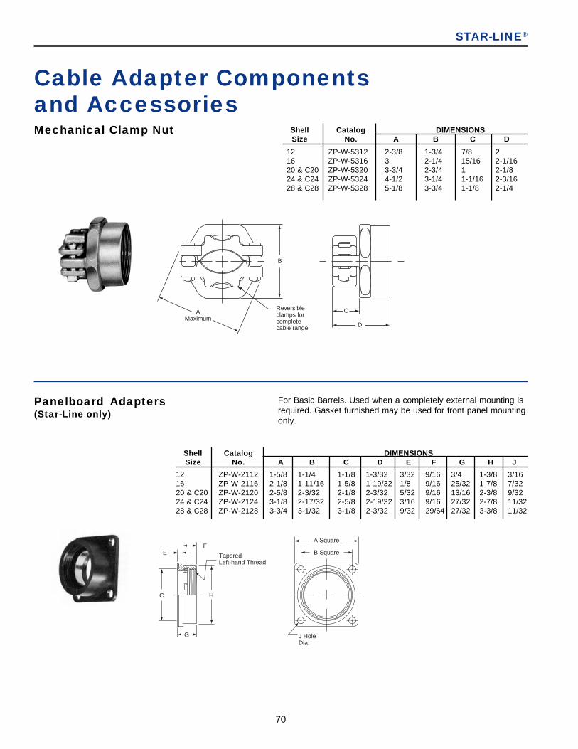
70
Panelboard Adapters(Star-Line only)
STAR-LINE®
Mechanical Clamp Nut Shell Catalog DIMENSIONSSize No. A B C D
12 ZP-W-5312 2-3/8 1-3/4 7/8 216 ZP-W-5316 3 2-1/4 15/16 2-1/1620 & C20 ZP-W-5320 3-3/4 2-3/4 1 2-1/824 & C24 ZP-W-5324 4-1/2 3-1/4 1-1/16 2-3/1628 & C28 ZP-W-5328 5-1/8 3-3/4 1-1/8 2-1/4
Cable Adapter Componentsand Accessories
For Basic Barrels. Used when a completely external mounting isrequired. Gasket furnished may be used for front panel mountingonly.
Shell Catalog DIMENSIONSSize No. A B C D E F G H J
12 ZP-W-2112 1-5/8 1-1/4 1-1/8 1-3/32 3/32 9/16 3/4 1-3/8 3/1616 ZP-W-2116 2-1/8 1-11/16 1-5/8 1-19/32 1/8 9/16 25/32 1-7/8 7/3220 & C20 ZP-W-2120 2-5/8 2-3/32 2-1/8 2-3/32 5/32 9/16 13/16 2-3/8 9/3224 & C24 ZP-W-2124 3-1/8 2-17/32 2-5/8 2-19/32 3/16 9/16 27/32 2-7/8 11/3228 & C28 ZP-W-2128 3-3/4 3-1/32 3-1/8 2-3/32 9/32 29/64 27/32 3-3/8 11/32
A Square
B Square
J HoleDia.
C H
FE
G
TaperedLeft-hand Thread
AMaximum
B
Reversibleclamps forcompletecable range D
C
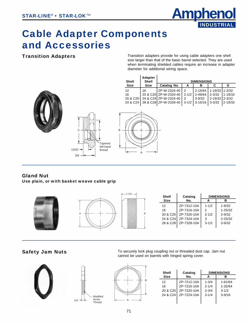
AmphenolINDUSTRIAL
71
STAR-LINE® • STAR-LOKTM
Transition Adapters Transition adapters provide for using cable adapters one shellsize larger than that of the basic barrel selected. They are usedwhen terminating shielded cables require an increase in adapterdiameter for additional wiring space.
AdapterShell Shell DIMENSIONSSize Size Catalog No. A B C D
12 16 ZP-W-2316-40 2 2-15/64 1-19/32 1-3/3216 20 & C20 ZP-W-2320-40 2-1/2 2-49/64 2-3/32 1-19/3220 & C20 24 & C24 ZP-W-2324-40 3 3-9/32 2-19/32 2-3/3224 & C24 28 & C28 ZP-W-2328-40 3-1/2 3-15/16 3-3/32 2-19/32
Gland NutUse plain, or with basket weave cable grip
A
1-1/4
B
Shell Catalog DIMENSIONSSize No. A B
12 ZP-7312-10A 1-1/2 1-9/3216 ZP-7316-10A 2 1-25/3220 & C20 ZP-7320-10A 2-1/2 2-9/3224 & C24 ZP-7324-10A 3 2-25/3228 & C28 ZP-7328-10A 3-1/2 3-9/32
Safety Jam Nuts To securely lock plug coupling nut or threaded dust cap. Jam nutcannot be used on barrels with hinged spring cover.
Cable Adapter Componentsand Accessories
Shell Catalog DIMENSIONSSize No. A B
12 ZP-7212-10A 1-3/4 1-61/6416 ZP-7216-10A 2-1/4 1-32/6420 & C20 ZP-7220-10A 2-3/4 3-1/224 & C24 ZP-7224-10A 3-1/4 3-9/16
13/32
3/8
C D
Taperedleft-handthread
B
A
ModifiedAcmeThread
1/4 A
B
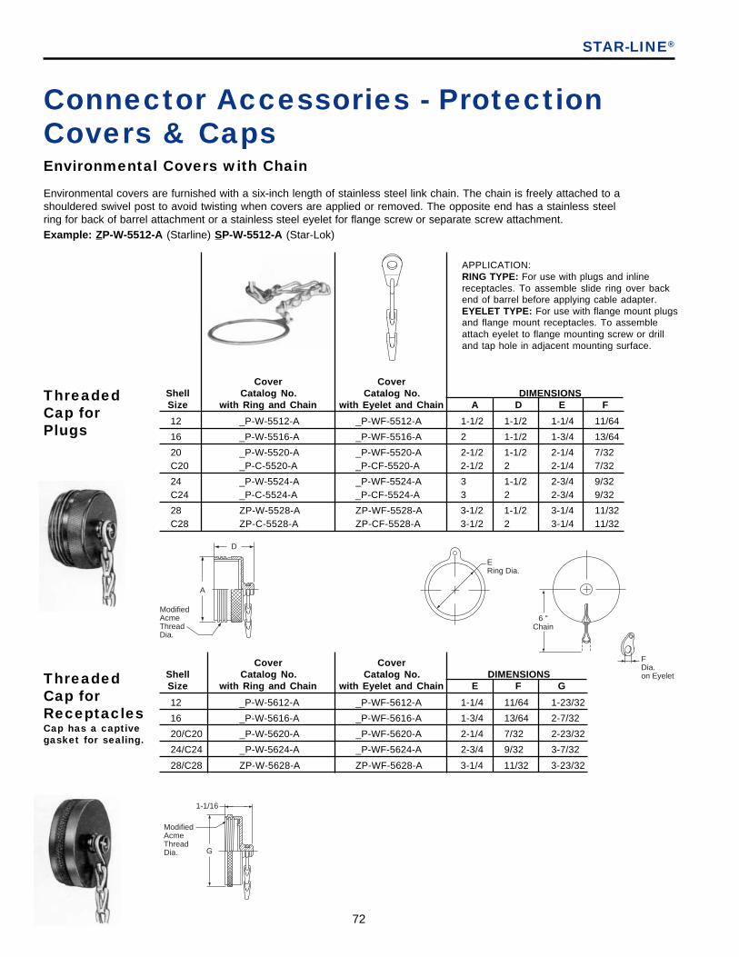
72
Environmental covers are furnished with a six-inch length of stainless steel link chain. The chain is freely attached to ashouldered swivel post to avoid twisting when covers are applied or removed. The opposite end has a stainless steelring for back of barrel attachment or a stainless steel eyelet for flange screw or separate screw attachment.Example: ZP-W-5512-A (Starline) SP-W-5512-A (Star-Lok)
Connector Accessories - ProtectionCovers & CapsEnvironmental Covers with Chain
APPLICATION:RING TYPE: For use with plugs and inlinereceptacles. To assemble slide ring over backend of barrel before applying cable adapter.EYELET TYPE: For use with flange mount plugsand flange mount receptacles. To assembleattach eyelet to flange mounting screw or drilland tap hole in adjacent mounting surface.
STAR-LINE®
Cover CoverShell Catalog No. Catalog No. DIMENSIONSSize with Ring and Chain with Eyelet and Chain A D E F
12 _P-W-5512-A _P-WF-5512-A 1-1/2 1-1/2 1-1/4 11/64
16 _P-W-5516-A _P-WF-5516-A 2 1-1/2 1-3/4 13/64
20 _P-W-5520-A _P-WF-5520-A 2-1/2 1-1/2 2-1/4 7/32C20 _P-C-5520-A _P-CF-5520-A 2-1/2 2 2-1/4 7/32
24 _P-W-5524-A _P-WF-5524-A 3 1-1/2 2-3/4 9/32C24 _P-C-5524-A _P-CF-5524-A 3 2 2-3/4 9/32
28 ZP-W-5528-A ZP-WF-5528-A 3-1/2 1-1/2 3-1/4 11/32C28 ZP-C-5528-A ZP-CF-5528-A 3-1/2 2 3-1/4 11/32
ThreadedCap forPlugs
ThreadedCap forReceptaclesCap has a captivegasket for sealing.
Cover CoverShell Catalog No. Catalog No. DIMENSIONSSize with Ring and Chain with Eyelet and Chain E F G
12 _P-W-5612-A _P-WF-5612-A 1-1/4 11/64 1-23/32
16 _P-W-5616-A _P-WF-5616-A 1-3/4 13/64 2-7/32
20/C20 _P-W-5620-A _P-WF-5620-A 2-1/4 7/32 2-23/32
24/C24 _P-W-5624-A _P-WF-5624-A 2-3/4 9/32 3-7/32
28/C28 ZP-W-5628-A ZP-WF-5628-A 3-1/4 11/32 3-23/32
ModifiedAcmeThreadDia.
D
A
1-1/16
ModifiedAcmeThreadDia. G
ERing Dia.
6 "Chain
FDia.on Eyelet

AmphenolINDUSTRIAL
73
Plastic Dust Caps
Hinged Spring Door Covers-Gasketed
D1D
L1L
For Receptacles For Plugs
For temporary protection of assembled barrels while in storage and shipment.
Covers have a stainless steel band to clamp over the coupling thread of female receptacles. The coverplate with a captive rubber gasket is pressed aluminum. A self-aligning seal is assured by the floatingaction of the cover on the center stainless-steel shouldered post. The hinge arm and support are machinedaluminum extrusions.
STAR-LINE® • STAR-LOKTM
Connector Accessories - ProtectionCovers & Caps
Shell Short Hinged Type DIMENSIONSSize Catalog No. A B C
12 ZP-C-5712 1-19/32 1-1/2 2-1/216 ZP-C-5716 1-19/32 1-3/4 2-3/420 & C20 ZP-C-5720 1-41/64 2-9/64 3-9/1624 & C24 ZP-C-5724 1-41/64 2-25/64 3-25/6428 & C28 ZP-C-5728 1-41/64 2-5/8 3-5/8
APPLICATION:SHORT HINGED TYPE:To clear standard coupling nut -Use with Square FlangeReceptacles when front or backmounted.
CB
A (Short Hinged Type)A1 (Long Hinged Type)
9/32
Shell Long Hinged Type DIMENSIONSSize Catalog No. A1 B C
12 ZP-C-5712-14 1-23/32 1-1/2 2-1/216 ZP-C-5716-14 1-23/32 1-3/4 2-3/420 & C20 ZP-C-5720-14 1-49/64 2-9/64 3-9/1624 & C24 ZP-C-5724-14 1-49/64 2-25/64 3-25/6428 & C28 ZP-C-5728-14 1-41/64 2-5/8 3-5/8
APPLICATION:LONG HINGED TYPE:To clear coupling jack nut -Use with Square FlangeReceptacles when frontmounted only.
Shell Plug Caps DIMENSIONSSize Catalog No. D1 L1
12 ZP-5512-11 1-13/32 11/1616 ZP-5516-11 1-29/32 11/1620 & C20 ZP-5520-11 2-3/8 11/1624 & C24 ZP-5524-11 2-29/32 11/1628 & C28 ZP-5528-11 3-11/16 1/2
Shell Receptacle Caps DIMENSIONSSize Catalog No. D L
12 ZP-5612-11 1-3/4 5/816 ZP-5616-11 2-1/4 11/1620 & C20 ZP-5620-11 2-22/32 21/3224 & C24 ZP-5624-11 3-7/32 21/3228 & C28 ZP-5628-11 3-15/16 1/2
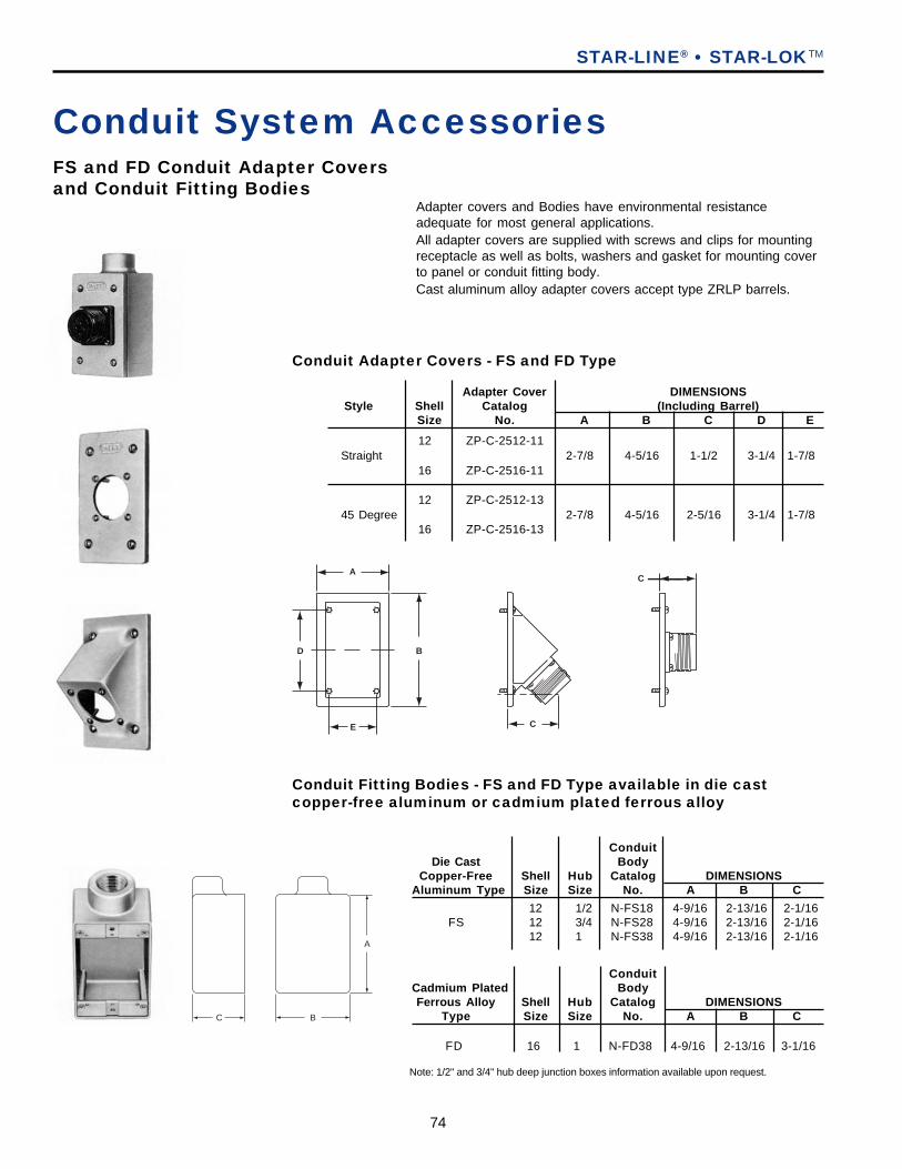
74
A
C B
Conduit Fitting Bodies - FS and FD Type available in die castcopper-free aluminum or cadmium plated ferrous alloy
Conduit System Accessories
STAR-LINE® • STAR-LOKTM
FS and FD Conduit Adapter Coversand Conduit Fitting Bodies
Adapter covers and Bodies have environmental resistanceadequate for most general applications.All adapter covers are supplied with screws and clips for mountingreceptacle as well as bolts, washers and gasket for mounting coverto panel or conduit fitting body.Cast aluminum alloy adapter covers accept type ZRLP barrels.
ConduitDie Cast Body
Copper-Free Shell Hub Catalog DIMENSIONSAluminum Type Size Size No. A B C
12 1/2 N-FS18 4-9/16 2-13/16 2-1/16FS 12 3/4 N-FS28 4-9/16 2-13/16 2-1/16
12 1 N-FS38 4-9/16 2-13/16 2-1/16
ConduitCadmium Plated BodyFerrous Alloy Shell Hub Catalog DIMENSIONS
Type Size Size No. A B C
FD 16 1 N-FD38 4-9/16 2-13/16 3-1/16
Note: 1/2" and 3/4" hub deep junction boxes information available upon request.
Adapter Cover DIMENSIONSStyle Shell Catalog (Including Barrel)
Size No. A B C D E
12 ZP-C-2512-11Straight 2-7/8 4-5/16 1-1/2 3-1/4 1-7/8
16 ZP-C-2516-11
12 ZP-C-2512-1345 Degree 2-7/8 4-5/16 2-5/16 3-1/4 1-7/8
16 ZP-C-2516-13
Conduit Adapter Covers - FS and FD Type
A
D B
E C
C

AmphenolINDUSTRIAL
75
STAR-LINE® • STAR-LOKTM
Conduit System AccessoriesAdapter covers and Bodies have environmental resistanceadequate for most general applications.All adapter covers are supplied with screws and clips for mountingreceptacle as well as bolts, washers and gasket for mounting coverto panel or conduit fitting body.Cast aluminum alloy adapter covers accept type ZRLP barrels.
Watertight Conduit Adapter Coversand Conduit Fitting Bodies
DIMENSIONSAdapter Cover (Including Barrel)
Style Shell Catalog F PitchSize No. A B C D UNC-2B
12 ZP-C-2512-10 4-3/16 3-9/16 1 1-27/32 1/4-20
16 ZP-C-2516-10 4-3/16 3-9/16 1 1-27/32 1/4-20
20/C20 ZP-C-2520-10 4-1/2 3-7/8 1-7/32 2-1/16 1/4-20
Straight 24 ZP-C-2524-10 8 7 1-1/2 2-9/16 1/2-13
C24 ZP-C-2524-10 8 7 1-1/2 2-27/32 1/2-13
28 ZP-C-2528-10 8 7 1-1/2 2-9/32 1/2-13
C28 ZP-C-2528-10 8 7 1-1/2 2-25/32 1/2-13
Above should not be used with pressure-type contact inserts.
Adapter Cover DIMENSIONSStyle (Including Barrel)
Shell Standard Deep F PitchSize Cat. No. Cat. No. A B C D UNC-2B
12 ZP-C-2512-12 4-3/16 3-9/16 2-13/16 2-7/16 1/4-20
16 ZP-C-2516-12 4-3/16 3-9/16 2-15/16 2-17/32 1/4-20
16 P-202704-16 4-3/16 3-9/16 4-7/16 4-1/16 1/4-20
20 4-1/2 3-7/8 3-39/64 3 1/4-20ZP-C-2520-12
C20 4-1/2 3-7/8 3-39/64 3-3/8 1/4-20
4-1/2 3-7/8 5 4-1/2 1/4-2020/C20 ZP-C-2520-26
4-1/2 3-7/8 5 4-7/8 1/4-20
24 8 7 3-33/64 2-19/64 1/2-13ZP-C-2524-12
C24 8 7 3-33/64 2-21/32 1/2-13
24 8 7 5-3/4 4-9/16 1/2-13P-202708-24
C24 8 7 5-3/4 5 1/2-13
28 8 7 3-5/8 2-7/16 1/2-13ZP-C-2528-12
C28 8 7 3-5/8 2-3/4 1/2-13
28 8 7 5-3/4 4-9/16 1/2-13P-202708-28
C28 8 7 5-3/4 5 1/2-13
Conduit Adapter Covers - Watertight Type
Conduit Adapter Covers cont.
Conduit ConduitShell Body Body DIMENSIONSSize Hub Size Cat. No. A1 A2 B C1 C2 D E F
3/4 P-202760-42 5-1/4 5-1/4 25/64 4-5/8 4-5/8 4-3/16 2-3/8 9/3212 or 16 1 P-202760-43 5-1/4 5-1/4 25/64 4-5/8 4-5/8 4-3/16 2-3/8 9/32
1-1/4 P-202760-64 5-1/4 5-1/4 25/64 4-5/8 4-5/8 4-3/16 2-3/8 9/321-1/2 P-202760-65 5-1/4 5-1/4 25/64 4-5/8 4-5/8 4-3/16 2-3/8 9/321-1/4 JRZ-610064 6 6 9/16 5-1/4 5-1/4 4-1/2 3-3/4 9/32
20 or C20 1-1/2 JRZ-610065 6 6 9/16 5-1/4 5-1/4 4-1/2 3-3/4 9/322 JRZ-610066 6 6 9/16 5-1/4 5-1/4 4-1/2 3-3/4 9/32
24 or C24 2-1/2 JR-720036-A SEE BOTTOM DRAWING 3-3/4 7/1628 or C28 3 JRZ-820036-A SEE BOTTOM DRAWING 4-1/2 7/16
D
C
F
116
A
A
B
B
Conduit Fitting Bodies – Cadmium Plated Ferrous Alloy
STANDARD COVER
DEEP COVER
STRAIGHT COVER
CONDUIT FITTINGBODYMount with hub at top,bottom or either side.
FITTING DIMENSIONS
8
8
53/8
91/2
5/8
5/8
E
D
A2 C2
A1C1
FPITCH
63/4
B
Shell sizes 24/C24 and 28/C28
D
C
FPITCH
116
A
A
B
B
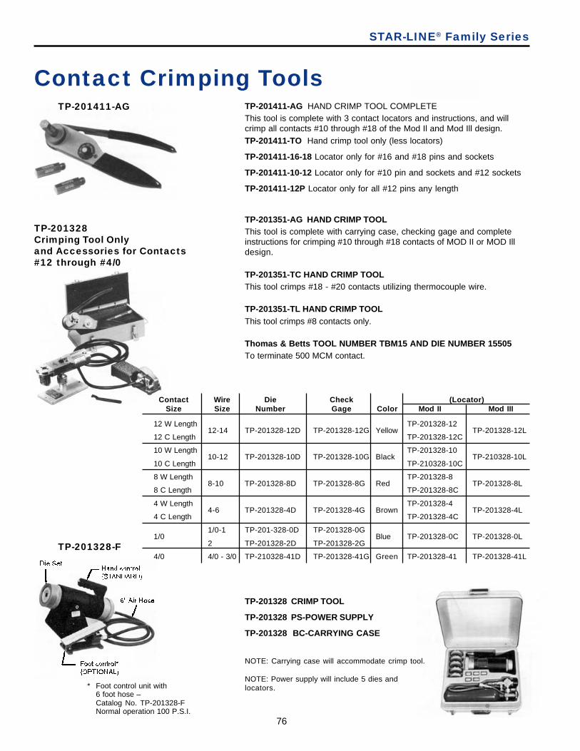
76
TP-201411-AG HAND CRIMP TOOL COMPLETEThis tool is complete with 3 contact Iocators and instructions, and willcrimp all contacts #10 through #18 of the Mod Il and Mod Ill design.TP-201411-TO Hand crimp tool only (less locators)
TP-201411-16-18 Locator only for #16 and #18 pins and sockets
TP-201411-10-12 Locator only for #10 pin and sockets and #12 sockets
TP-201411-12P Locator only for all #12 pins any length
Contact Crimping Tools
TP-201351-AG HAND CRIMP TOOLThis tool is complete with carrying case, checking gage and completeinstructions for crimping #10 through #18 contacts of MOD II or MOD Illdesign.
TP-201351-TC HAND CRIMP TOOLThis tool crimps #18 - #20 contacts utilizing thermocouple wire.
TP-201351-TL HAND CRIMP TOOLThis tool crimps #8 contacts only.
Thomas & Betts TOOL NUMBER TBM15 AND DIE NUMBER 15505To terminate 500 MCM contact.
TP-201328Crimping Tool Onlyand Accessories for Contacts#12 through #4/0
TP-201328 CRIMP TOOL
TP-201328 PS-POWER SUPPLY
TP-201328 BC-CARRYING CASE
NOTE: Carrying case will accommodate crimp tool.
NOTE: Power supply will include 5 dies andlocators.
TP-201328-F
TP-201411-AG
STAR-LINE® Family Series
* Foot control unit with6 foot hose –Catalog No. TP-201328-FNormal operation 100 P.S.I.
Contact Wire Die Check (Locator)Size Size Number Gage Color Mod II Mod III
12 W Length TP-201328-1212-14 TP-201328-12D TP-201328-12G Yellow TP-201328-12L
12 C Length TP-201328-12C
10 W Length TP-201328-1010-12 TP-201328-10D TP-201328-10G Black TP-210328-10L
10 C Length TP-210328-10C
8 W Length TP-201328-88-10 TP-201328-8D TP-201328-8G Red TP-201328-8L
8 C Length TP-201328-8C
4 W Length TP-201328-44-6 TP-201328-4D TP-201328-4G Brown TP-201328-4L
4 C Length TP-201328-4C
1/0-1 TP-201-328-0D TP-201328-0G1/0 Blue TP-201328-0C TP-201328-0L
2 TP-201328-2D TP-201328-2G
4/0 4/0 - 3/0 TP-210328-41D TP-201328-41G Green TP-201328-41 TP-201328-41L
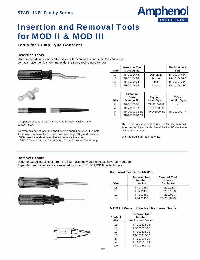
AmphenolINDUSTRIAL
77
MOD III Pin and Socket Removal Tools
Insertion and Removal Toolsfor MOD II & MOD III
A separate expander barrel is required for each cavity of thecontact inset.
An even number of long and short barrels should be used: Example:if the insert contains four cavities, use two long (EBL) and two short(EBS). Insert the short ones first and remove them last.NOTE: EBS = Expander Barrel Short, EBL= Expander Barrel Long.
Tools for Crimp Type Contacts
Insertion ToolsUsed for inserting contacts after they are terminated to conductor. Pin and socketcontacts have identical terminal ends; the same tool is used for both.
The T-Bar handle should be used in the insertion andextraction of the expander barrel for the 1/0 cavities –only one is required.
One tapered lead required only.
Removal Tools for MOD II
STAR-LINE® Family Series
Insertion Tool ReplacementSize Catalog No. Tips
18 TP-201047-1 Use Same TP-201047-PA16 TP-201048-1 Tool for TP-201048-PA12 TP-201049-1 Pin or TP-201049-PA10 TP-201046-1 Socket TP-201046-PA
Removal ToolsUsed for extracting contacts from the insert assembly after contacts have been seated.Expanders and taper leads are required for sizes 8, 4, 1/0 MOD II contacts only.
ExpanderBarrel Tapered T-Bar
Size Catalog No. Lead Style Handle Style
8 TP-201007-A TP-201007-B –4 TP-201033-A TP-201033-B –0 TP-201000-EBL TP-201000-TL TP-201000-TH0 TP-201000-EBS
Removal Tool Removal ToolNumber Number
Size for Pin for Socket
18 TP-201459 TP-201011-316 TP-201459 TP-201010-312 TP-201459 TP-201009-310 TP-201459 TP-201008-3
Removal ToolContact Number
Size for Pin and Socket
18 TP-201315-1816 TP-201315-1612 TP-201315-1210 TP-201315-108 TP-201315-084 TP-201315-04
1/0 TP-201260-00
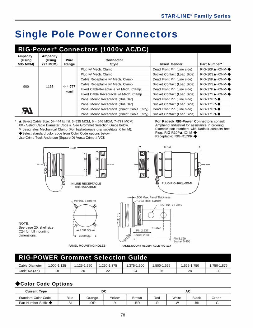
78
Cable Diameter 1.000-1.125 1.125-1.250 1.250-1.375 1.375-1.500 1.500-1.625 1.625-1.750 1.750-1.875
Code No.(XX) 18 20 22 24 26 28 30
8.703
PLUG RIG-10X -XX-M
Plug w/ Mech. Clamp Dead Front Pin (Line side) RIG-10P▲-XX-M-◆
Plug w/ Mech. Clamp Socket Contact (Load Side) RIG-10S▲-XX-M-◆
Cable Receptacle w/ Mech. Clamp Dead Front Pin (Line side) RIG-15P▲-XX-M-◆
Cable Receptacle w/ Mech. Clamp Socket Contact (Load Side) RIG-15S▲-XX-M-◆
Fixed CableReceptacle w/ Mech. Clamp Dead Front Pin (Line side) RIG-17P▲-XX-M-◆
Fixed Cable Receptacle w/ Mech. Clamp Socket Contact (Load Side) RIG-17S▲-XX-M-◆
Panel Mount Receptacle (Bus Bar) Dead Front Pin (Line side) RIG-17PR-◆
Panel Mount Receptacle (Bus Bar) Socket Contact (Load Side) RIG-17SR-◆
Panel Mount Receptacle (Direct Cable Entry) Dead Front Pin (Line side) RIG-17PN-◆
Panel Mount Receptacle (Direct Cable Entry) Socket Contact (Load Side) RIG-17SN-◆
Single Pole Power Connectors
RIG-POWER Grommet Selection Guide
.500 Max. Panel Thickness.063 Thick Gasket
.656 Dia. 2 Holes
1.750
Pin 5.199Socket 5.455
Pin 2.637
Socket 2.833
PANEL MOUNT RECEPTACLE RIG-17X
NOTE:See page 20, shell sizeC24 for full mountingdimensions.
8.734
IN-LINE RECEPTACLERIG-15X -XX-M
PANEL MOUNTING HOLES
.297 DIA. 4 HOLES
2.531 SQ.
3.250 SQ.
* ▲ Select Cable Size: (4=444 kcmil, 5=535 MCM, 6 = 646 MCM, 7=777 MCM)XX - Select Cable Diameter Code #. See Grommet Selection Guide below.M designates Mechanical Clamp (For basketweave grip substitute K for M).◆ Select standard color code from Color Code options below.Use Crimp Tool: Anderson (Square D) Versa Crimp # VC8
RIG-Power® Connectors (1000v AC/DC) Ampacity Ampacity
(Using (Using Wire Connector535 MCM) 777 MCM) Range Style Insert Gender Part Number*
900 1135 444-777
kcmil
◆ Color Code Options
Standard Color Code Blue Orange Yellow Brown Red White Black Green
Part Number Suffix ◆ -BL -OR -Y -BR -R -W -BK -G
Current Type DC AC
STAR-LINE® Family Series
®
For Radsok RIG-Power Connectors consultAmphenol Industrial for assistance in ordering.Example part numbers with Radsok contacts are:Plug: RIG-R10P▲-XX-M-◆Receptacle: RIG-R17PR-◆
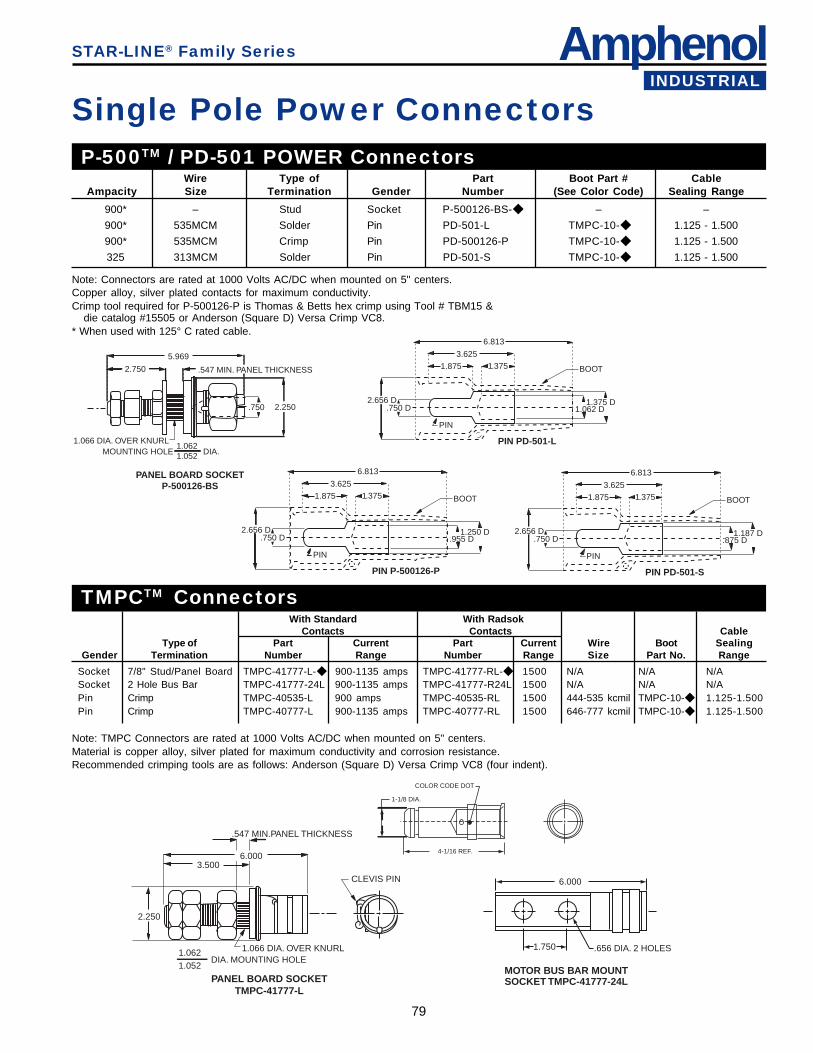
AmphenolINDUSTRIAL
79
PANEL BOARD SOCKETTMPC-41777-L
DIA. MOUNTING HOLE1.066 DIA. OVER KNURL1.062
1.052
2.250
3.5006.000
.547 MIN.PANEL THICKNESS
CLEVIS PIN
5.969
2.750 .547 MIN. PANEL THICKNESS
.750 2.250
1.066 DIA. OVER KNURLMOUNTING HOLE DIA.
1.0621.052
PANEL BOARD SOCKETP-500126-BS
1.875
3.6251.375 BOOT
1.250 D.955 D
PIN
.750 D2.656 D
6.813
PIN P-500126-P
1.875
3.6251.375 BOOT
1.375 D1.062 D
PIN
.750 D2.656 D
6.813
PIN PD-501-L
Wire Type of Part Boot Part # CableAmpacity Size Termination Gender Number (See Color Code) Sealing Range
P-500TM / PD-501 POWER Connectors
900* – Stud Socket P-500126-BS-◆ – –
900* 535MCM Solder Pin PD-501-L TMPC-10-◆ 1.125 - 1.500
900* 535MCM Crimp Pin PD-500126-P TMPC-10-◆ 1.125 - 1.500
325 313MCM Solder Pin PD-501-S TMPC-10-◆ 1.125 - 1.500
1.875
3.6251.375 BOOT
1.187 D.875 D
PIN
.750 D2.656 D
6.813
PIN PD-501-S
Note: Connectors are rated at 1000 Volts AC/DC when mounted on 5" centers.Copper alloy, silver plated contacts for maximum conductivity.Crimp tool required for P-500126-P is Thomas & Betts hex crimp using Tool # TBM15 &
die catalog #15505 or Anderson (Square D) Versa Crimp VC8.* When used with 125° C rated cable.
With Standard With RadsokContacts Contacts Cable
Type of Part Current Part Current Wire Boot SealingGender Termination Number Range Number Range Size Part No. Range
Note: TMPC Connectors are rated at 1000 Volts AC/DC when mounted on 5" centers.Material is copper alloy, silver plated for maximum conductivity and corrosion resistance.Recommended crimping tools are as follows: Anderson (Square D) Versa Crimp VC8 (four indent).
TMPCTM Connectors
.656 DIA. 2 HOLES
6.000
1.750
MOTOR BUS BAR MOUNTSOCKET TMPC-41777-24L
STAR-LINE® Family Series
Single Pole Power Connectors
COLOR CODE DOT
4-1/16 REF.
1-1/8 DIA.
Socket 7/8" Stud/Panel Board TMPC-41777-L-◆ 900-1135 amps TMPC-41777-RL-◆ 1500 N/A N/A N/ASocket 2 Hole Bus Bar TMPC-41777-24L 900-1135 amps TMPC-41777-R24L 1500 N/A N/A N/APin Crimp TMPC-40535-L 900 amps TMPC-40535-RL 1500 444-535 kcmil TMPC-10-◆ 1.125-1.500Pin Crimp TMPC-40777-L 900-1135 amps TMPC-40777-RL 1500 646-777 kcmil TMPC-10-◆ 1.125-1.500

80
STAR-LINE Connector Assemblyand Termination Instructions
STAR-LINE® Family Series
Proper assembly of multiple-contact connectors, for the most part requires common sense. The simplicity ofthese instructions is perhaps the reason why they are easily overlooked or taken for granted.These 27 reminders can help eliminate connector failures caused by improper assembly.
1. Read the assembly instructions carefully before actually startingto assemble connectors. Besides the matter of instruction oncorrect procedures, there are two important reasons for thispreliminary step: To identify the various component parts, andto check for any missing parts.
2. Cut cable jackets and sheathing squarely and to correct length,using only wire strippers that have been approved for theoperation. In preparing the individual wires in cables andharnesses for assembly, make allowances in length forreaching the outermost circle of contact cavities in the connec-tor insert. This, of course, means that the conductors and theinsulation should be cut progressively longer as they extend outfrom the center of the cable or harness to assure sufficientlength for any necessary forming.
3. Follow specifications covering maximum cable stripping lengthsfor efficient cable grommet sealing. All wires should be cutsquarely so that they will fit into contact wire wells correctly.
4. Before starting actual termination wires, it is essential thatcables and harnesses be laid out in a specified order inaccordance with the wiring diagram. Proper layout will reducethe need for twisting and crossover of conductors. If the wiringlayout is not correct, the termination operation will be difficult oreven impossible and the chances for making errors will beincreased. Cable and harness assemblies having a spiral layoutalso must be matched carefully to the correct contacts in boththe male and female inserts.
5. Some cables have a soft filler or braid on the conductors which,compresses when external pressure is applied. As a result, thecable diameter may be reduced to a point where the sealingrange of the grommet is exceeded. In addition, the seal maytake a permanent set and further reduce sealing efficiency. Toavoid leakage at the seal under these conditions, it is suggestedthat, where construction of the cable permits, a metal ferrule beslipped under the cable jacket at the stressed position. Thisferrule will serve as a compression supporting member andenable the gland seal to withstand high external pressures.
6. Use only correct size sealing grommets to assure resistance tomoisture and other contaminants. Make certain that cable jacketis smooth where grommet is to seal. Remove any grooves orridges if present by sanding or scarfing.
7. Use only the proper crimping tools that have been set orcalibrated with precision gages.
8. When contacts are to be soldered, avoid direct contact ofsoldering tools to inserts. An open flame or hot soldering tip cancarbonize insulating materials and make them useless.
9. Make certain that all contacts are the correct size beforeattempting to assemble them into insert cavities. This point isparticularly important when both power and control types ofcontacts are used in the same connector.
10. Be sure that grounding contacts are correctly located.
11. Seat all contacts properly so that they will not be damaged orbecome disengaged during connector mating operations.
12. Use only the proper insertion tools and be sure that they arealigned axially when pushing contacts into their fully seatedposition.
13. When inserts have more cavities than conductors, plug unusedcavities with either plain contacts or special seal plugs designedfor the purpose. Some connectors require both a contact andseal plug in unused cavities to meet military specifications andto assure complete internal environmental sealing.
14. After all terminated contacts are inserted in their respectivecavities and inspected, the cable adapter or insert clamp nutshould be tightened with a wrench. This assembly operationshould be done by placing the components in a vise withsmooth-faced jaws and using a strap wrench.
15. If for any reason terminated conductors have to be removedfrom an insert because of any assembly error or change incircuitry, be sure to remove the cable clamp or insert clamp nutfirst before extracting the contact and reinserting it. This step isimportant because any attempt to remove the contacts whenthe resilient insulator components are compressed will result indamage.
16. When handling cables, use adequate support to preventdamage to the internal wires. Gland nuts and grommets areintended for sealing purposes and should not be used as acable grip.
17. If one of the connector poles is a grounding wire, make surethat it is grounded properly before the connector is actuallyengaged.
18. When connectors having the same configuration are to bemounted close together, different or alternate keying arrange-ments should be used to prevent mismating or cross-matingand possible damage to the electrical system or human injury.
19. Always inspect all aspects of connector assembly operationsbefore putting connectors into actual operation.
20. Crimping and terminating of conductors to contacts must bedone carefully. Make certain that wire strands are fullybottomed in contact wells by checking through inspection holeprovided.
21. Soldering conductors to contacts must be done carefully and anon-conductive flux should be used to avoid corrosion orhygroscopic action. Do not use solder salts or acids becausethey may affect the dielectric properties of insulation materials.
22. Be careful not to damage wire grommets or contact retainingcollets when inserting or extracting contacts.
23. Never try to straighten bent contacts. Straightening cannot bedone properly and the plating on contacts will very likely bemarred. This will result in a high resistance connection and willexpose the base metal to possible corrosion.
24. Do not attempt to remove inserts that are bonded or locked inplace in their shells.
25. Be certain that all components of connectors are assembled.Each part performs a vital function and it would not be includedif it wasn't useful.
26. Each assembler of connectors should be his own inspector.Assembly workmanship is a significant factor in determining thequality of multiple-contact connectors. Quality cannot be"inspected" into connectors; it must be "built-in" during each andevery assembly operation.
27. When potting connectors be sure to apply potting only in matedcondition to assure that contacts will align properly.

AmphenolINDUSTRIAL
81
STAR-LINE Connectors withRADSOK® Contacts
STAR-LINE® Family Series
The new RADSOK contactdesign has been incorporatedinto the Star-Line connectorfamily of connectors.
Insert arrangements withRADSOK's are shown in thiscatalog. For information onavailability of additional insertswith RADSOK's consult AmphenolIndustrial Operations.Amphe-Power connectors withRADSOK sockets can handle up to 150% higher amperages than connec-tors with standard contacts. Current Amphe-Power product lines support from50A to 500A continuous duty. RADSOK contacts are available in size 8 (69amps), size 4 (120 amps), and size 0 (250 amps).
RADSOK Contact Advantages:• Low contact resistance - the RADSOK contact’s multiplicity of flat grid
surfaces assures the greatest possible contact area on the mating pin.This results in longer life - reduced contact pressure yields reduced wear.
• Low milli-volt drop performance - due to the intimate contact provided bythe spring force of the grid, the flat contact surface and the wiping actionduring insertion.
• Higher current capacity with minimized temperature rise. Lower overallcontact resistance reduces heat build-up, thereby allowing higher currentcapacities at given temperature limits. Connectors with RADSOK contactsmay be produced in various sizes with a variety of amperage capabilities.
• Reliability under vibration and shock. System inertia is minimized by thesmall package and the fact that the contact is under a spring load.
• High quality, consistency and lower cost with high speed, automatedprecision stamping and assembly technology
See Brochure SL-391, Amphenol Amphe-Power Connectors with RADSOKTechnology for more information on other Amphenol connector types thatincorporate RADSOK contacts.
RADSOK Contact Design:• Socket cylinder within female contact has
several equally spaced longitudinal beamstwisted into a hyperbolic shape.
• As male pin is inserted, axial members inthe female half deflect, imparting highcurrent flow across the connection withminimal voltage loss.
• The hyperbolic, stamped grid configurationensures a large, coaxial, face-to-facesurface area engagement.
• Ideal for crimp termination applicationsrequiring repeated mating cycles and highcurrent with a low milli-volt drop.
Certain designs are available for variablefrequency drive (VFD) applications. ConsultAmphenol Industrial Operations for furtherinformation.

82
Additional Amphenol® IndustrialConnector Products
Neptune® SeriesAmphenol Industrial Operations has introduced a new power connector family that features theAmphenol exclusive RADSOK® contact system. This new Neptune® connector series is designedto perform in the most demanding environments. It features the same aluminum constructions withanodic hardcoat plated components as the Star-Line product.The RADSOK contact provides increased amperage. See page 81 for more information onRADSOK contact features and benefits.Other features: 30 Amp through 400 Amp/480 Volt inserts available; decreased weight and panellayout compared to competition; double lead Acme threads for easy coupling.Used in oil exploration equipment, convention center power distribution, portable power distributionequipment, geophysical trucks, and communication shelters.
Reference Product Data Sheet #192
Amphenol Cord GripsAmphenol's industrial product offering also includes a wide variety of cord grips that provide liquidtight strain relief for cord, cable and flexible conduit. They have threaded coupling for panel boardor threaded hub applications. Straight, 45 degree or 90 degree styles. Moisture sealing is providedwith oil-resistant grommets and compression nuts. Tapered conduit threads assure strong waterand oil-tight joints. UL listed and CSA certified.
Reference Catalog 12-055
Amphenol Cable GlandsAmphenol Industrial Operations, the worldwide leader of explosion proof and hazardous environ-ment interconnects, introduces a broad range of explosion proof and industrial cable glands. Thecable gland products are designed to perform in the most demanding environments. Amphenolprovides a complete line of EX Zone 1 and 2 rated cable glands along with general duty cableglands that are suitable for armored and unarmored cable. Brass and stainless steel types areavailable. IP66/68; deluge; NEMA rated products. SIRA/ATEX certified to Exd/Exe (Class I, Div. I)and CSA approved.
Reference Catalog 12-055
Overmolded Cable AssembliesCables can be designed with a custom overmold to any Amphenol cylindrical connector for almostany industrial application. Overmold seals to the rear of the connector and to the cable jacketproviding moisture sealing. A variety of materials are available: Neoprene, Hypalon and others.Lengths and configurations are designed to meet customer specifications.
Consult Amphenol Industrial Operations, Sidney, NY
Amphenol's combination of cable glands and cord gripproducts, along with their design and manufacturing expertisein cable assemblies makes Amphenol Industrial the one-stopsupplier for connector and cable sealing solutions.

AmphenolINDUSTRIAL
83
GT-SeriesAmphenol GT Series of connectors are heavy duty, rugged and environmentally resistant. They have reversebayonet coupling which provides quick mating, audible, visual and tactile full mating indicators. They incorporate5015 inserts, available in Neoprene, Viton or low smoke/flame retardant material. Over 40 varieties of shell stylesand backend accessory combinations. Rugged construction - aluminum or stainless steel components.Other features and benefits include: UL recognized; rated to 2000 couplings min., available in both crimp andsolder terminations. Numerous military and commercial finishes available including cadmium free zinc alloy.Used in mass transportation, power generation, petrochemical applications, heavy equipment and geophysicalapplications.
Reference Catalog 12-024
Additional Amphenol® IndustrialConnector Products
MIL-C-26482A medium size cylindrical connector family with a wide variety of styles. MS versions are produced in strictaccordance to MIL-C-26482, Series 1 with several non-MS types also offered. MS-PT Service classes E, F andF types are UL recognized.Styles include three point bayonet coupling, crimp, solder or printed board termination. Resilient inserts providehigh dielectric strength and moisture barrier. There are 7 shell styles including hermetics, and 57 insert patterns.Variety of finishes, contact options and backend accessories options.Used in instrumentation, machine tool, communications and geophysical applications.
Reference Catalog 12-070
MIL-5015Amphenol has long been the accepted leader in providing MS/Standard MIL-5015 type connectors. The AmphenolMS/Standard product is a large family of time-tested medium to heavyweight connectors with resilient inserts,threaded coupling. Other features include: over 200 insert arrangements, both crimp and solder terminations,plating options including cadmium-free.There are five classes to meet different requirements: A- solid shell, for general, non-environmental applications;C- pressurized, for use on pressurized bulkheads or pressure barriers; E/F - environmental resisting with strainreliefs, designed for applications where the connector with be exposed to moisture, vibration and rapid changes inpressure and temperature; R- lightweight environmental resisting, shorter in weight than the E/F classes.Used in heavy equipment, off-road vehicles, mass transportation and power generation.
Reference Catalog 12-020
Amphe-Lite SeriesAmphenol offers a commercial 38999, Series III type connector for higher performance industrial usage. Thisfamily offers 38999 type high performance capabilities for severe environment applications, yet is cost effectiveenough for general duty and non-environmental use as well. There is a class which provides an excellent EMIshielding and a class that provides a non-conductive finish. Composite shells resist severe corrosion.The Amphe-lite series has 3 shell styles and 59 insert patterns available. It offers wide versatility in contactoptions such as twinax, coax, filter contacts and fiber optic termini, which makes it ideal for usage in communica-tions equipment, medical equipment and automotive applications.
Reference Catalog 12-094
For an overview of Amphenol Industrial Connector Products ask for Amphenol brochure SL-381. Call your local Amphenol sales office or 800-678-0141 for further information. TheIndustrial Overview brochure and all the product brochures listed above can be viewed,printed and downloaded from the Amphenol website: www.amphenol-industrial.com.