Embed Size (px)
Citation preview

Helios Gene Gun SystemInstruction Manual
Catalog Number # 1652431 1652432

II | Helios Gene Gun System
Warranty and Regulatory Notices Warranty StatementThe Helios Gene Gun System and associated accessories are covered by a standard Bio-Rad warranty. Contactyour local Bio-Rad Laboratories office for details of the warranty.
Regulatory NoticesImportant: This Bio-Rad instrument is designed and certified to meet EN/IEC 61010-1:2010 (3rd Edition), EN61326-1:2013 Class A, and EN50581:2012 requirements, which are internationally accepted electromagnetic compliance and electrical safety standards. Certified products are safe to use when operated in accordance with the instruction manual. This instrument should not be modified or altered in any way. Alteration of this instrument will void the manufacturer’s warranty, void the regulatory certifications, and create a potential safety hazard.
Note: This equipment has been tested and found to comply with the limits for a Class A digital device, pursuant to Part 15 of the FCC rules. These limits are designed to provide reasonable protection against harmful interference when the equipment is operated in a commercial environment. This equipment generates, uses, and can radiate radiofrequency energy and, if not installed and used in accordance with the instruction manual, may cause harmful interference to radio communications. Operation of this equipment in a residential area is likely to cause harmful interference in which case the user will be required to correct the interference at his own expense.

Helios Gene Gun System | III
Table of ContentsSection 1 General Safety Information . . . . . . . . . . . . . . . . . . . . . . . . . . . . . . . . . . . . . . . . . . . . . . . . . . . . . . . . 1 Helios Gene Gun Safety . . . . . . . . . . . . . . . . . . . . . . . . . . . . . . . . . . . . . . . . . . . . . . . . . . . . . . . . . . 1 Pressurized Helium and Nitrogen Safety . . . . . . . . . . . . . . . . . . . . . . . . . . . . . . . . . . . . . . . . . . . . . . 1 Power Safety . . . . . . . . . . . . . . . . . . . . . . . . . . . . . . . . . . . . . . . . . . . . . . . . . . . . . . . . . . . . . . . . . . . 2 Ear and Eye Protection . . . . . . . . . . . . . . . . . . . . . . . . . . . . . . . . . . . . . . . . . . . . . . . . . . . . . . . . . . . 2
Section 2 Introduction to Particle Delivery . . . . . . . . . . . . . . . . . . . . . . . . . . . . . . . . . . . . . . . . . . . . . . . . . . . . . 3 Particle Delivery Technology . . . . . . . . . . . . . . . . . . . . . . . . . . . . . . . . . . . . . . . . . . . . . . . . . . . . . . . 3 The Helios Gene Gun . . . . . . . . . . . . . . . . . . . . . . . . . . . . . . . . . . . . . . . . . . . . . . . . . . . . . . . . . . . . 3 Operating Principle of the Helios Gene Gun System . . . . . . . . . . . . . . . . . . . . . . . . . . . . . . . . . . . . . 4 Requirements for System Operation . . . . . . . . . . . . . . . . . . . . . . . . . . . . . . . . . . . . . . . . . . . . . . . . . 5 User Supplied Components . . . . . . . . . . . . . . . . . . . . . . . . . . . . . . . . . . . . . . . . . . . . . . . . . . . . . . . 6
Section 3 Product Description. . . . . . . . . . . . . . . . . . . . . . . . . . . . . . . . . . . . . . . . . . . . . . . . . . . . . . . . . . . . . . 8 Packing List . . . . . . . . . . . . . . . . . . . . . . . . . . . . . . . . . . . . . . . . . . . . . . . . . . . . . . . . . . . . . . . . . . . . 8 Identification of System Components and Controls . . . . . . . . . . . . . . . . . . . . . . . . . . . . . . . . . . . . . 10
Section 4 Inserting the Battery into the Helios Gene Gun . . . . . . . . . . . . . . . . . . . . . . . . . . . . . . . . . . . . . . . . 14 Connecting the Helios Gene Gun to a Helium Source . . . . . . . . . . . . . . . . . . . . . . . . . . . . . . . . . . . 15 Setting Up the Tubing Prep Station . . . . . . . . . . . . . . . . . . . . . . . . . . . . . . . . . . . . . . . . . . . . . . . . . 16
Section 5 Operation of the Helios Gene Gun System . . . . . . . . . . . . . . . . . . . . . . . . . . . . . . . . . . . . . . . . . . . 19 Quick Guide to Operation . . . . . . . . . . . . . . . . . . . . . . . . . . . . . . . . . . . . . . . . . . . . . . . . . . . . . . . . 19 Preparation of System Components Prior to Bombardment . . . . . . . . . . . . . . . . . . . . . . . . . . . . . . 20 Particle Delivery Using the Helios Gene Gun System . . . . . . . . . . . . . . . . . . . . . . . . . . . . . . . . . . . 26 Removing Used Cartridges, Depressurization, and Shutdown . . . . . . . . . . . . . . . . . . . . . . . . . . . . 31
Section 6 Preparation of Mammalian Cell Targets . . . . . . . . . . . . . . . . . . . . . . . . . . . . . . . . . . . . . . . . . . . . . . 32 In Vitro Delivery to Adherent Cells . . . . . . . . . . . . . . . . . . . . . . . . . . . . . . . . . . . . . . . . . . . . . . . . . . 32 In Vitro Delivery to Suspension Cultures . . . . . . . . . . . . . . . . . . . . . . . . . . . . . . . . . . . . . . . . . . . . . 33 In Vivo Delivery to Epidermis . . . . . . . . . . . . . . . . . . . . . . . . . . . . . . . . . . . . . . . . . . . . . . . . . . . . . . 35
Section 7 Optimization of Gene Gun Parameters . . . . . . . . . . . . . . . . . . . . . . . . . . . . . . . . . . . . . . . . . . . . . . 36 Overview . . . . . . . . . . . . . . . . . . . . . . . . . . . . . . . . . . . . . . . . . . . . . . . . . . . . . . . . . . . . . . . . . . . . . 36 Parameters for In Vitro Delivery . . . . . . . . . . . . . . . . . . . . . . . . . . . . . . . . . . . . . . . . . . . . . . . . . . . . 38 Parameters for In Vivo Delivery . . . . . . . . . . . . . . . . . . . . . . . . . . . . . . . . . . . . . . . . . . . . . . . . . . . . 39
Section 8 Troubleshooting . . . . . . . . . . . . . . . . . . . . . . . . . . . . . . . . . . . . . . . . . . . . . . . . . . . . . . . . . . . . . . . . 39 DNA/Microcarrier Preparation . . . . . . . . . . . . . . . . . . . . . . . . . . . . . . . . . . . . . . . . . . . . . . . . . . . . . 39 Cartridge Preparation . . . . . . . . . . . . . . . . . . . . . . . . . . . . . . . . . . . . . . . . . . . . . . . . . . . . . . . . . . . 39 Helios Gene Gun Operation . . . . . . . . . . . . . . . . . . . . . . . . . . . . . . . . . . . . . . . . . . . . . . . . . . . . . . 40 In Vitro and In Vivo Targeting . . . . . . . . . . . . . . . . . . . . . . . . . . . . . . . . . . . . . . . . . . . . . . . . . . . . . . 40
Section 9 Product Information . . . . . . . . . . . . . . . . . . . . . . . . . . . . . . . . . . . . . . . . . . . . . . . . . . . . . . . . . . . . . 41 Helios Gene Gun System . . . . . . . . . . . . . . . . . . . . . . . . . . . . . . . . . . . . . . . . . . . . . . . . . . . . . . . . 41 Spare Parts . . . . . . . . . . . . . . . . . . . . . . . . . . . . . . . . . . . . . . . . . . . . . . . . . . . . . . . . . . . . . . . . . . . 42 Gene Gun Specifications . . . . . . . . . . . . . . . . . . . . . . . . . . . . . . . . . . . . . . . . . . . . . . . . . . . . . . . . . 42 Tubing Prep Station Specifications . . . . . . . . . . . . . . . . . . . . . . . . . . . . . . . . . . . . . . . . . . . . . . . . . 43
Section 10 Appendices . . . . . . . . . . . . . . . . . . . . . . . . . . . . . . . . . . . . . . . . . . . . . . . . . . . . . . . . . . . . . . . . . . . 43 Precipitation of RNA onto Microcarriers . . . . . . . . . . . . . . . . . . . . . . . . . . . . . . . . . . . . . . . . . . . . . . 43 Replacing the O-Rings and Barrel Liner on the Helios Gene Gun . . . . . . . . . . . . . . . . . . . . . . . . . . 44 Replacing the O-Ring on the Tubing Prep Station . . . . . . . . . . . . . . . . . . . . . . . . . . . . . . . . . . . . . . 45 Replacement of Razor Blade on and Disassembly of the Tubing Cutter . . . . . . . . . . . . . . . . . . . . . 45 Cleaning and Sterilizing the Helios Gene Gun . . . . . . . . . . . . . . . . . . . . . . . . . . . . . . . . . . . . . . . . . 47 Testing Cartridges for Microcarrier Penetration and Density (Optional) . . . . . . . . . . . . . . . . . . . . . . 47 Quantification of DNA in Cartridges . . . . . . . . . . . . . . . . . . . . . . . . . . . . . . . . . . . . . . . . . . . . . . . . . 50 References . . . . . . . . . . . . . . . . . . . . . . . . . . . . . . . . . . . . . . . . . . . . . . . . . . . . . . . . . . . . . . . . . . . 51 Quick Guide to Operation . . . . . . . . . . . . . . . . . . . . . . . . . . . . . . . . . . . . . . . . . . . . . . . . . . . . . . . . 52

IV | Helios Gene Gun System

Section 1 General Safety Information
Helios Gene Gun System | 1
Section 1 General Safety Information
Section 1 General Safety Information
Caution: In particle bombardment DNA-coated microparticles are accelerated to velocities in excess of 1,000 ft/sec in order to penetrate the cell membrane and through multiple layers of cells in tissues and organs. In the Helios Gene Gun, this accelerating force is supplied by a high-pressure helium pulse. Numerous safety features have been designed into this instrument to protect both the user and bystanders. The parts used in manufacturing the Helios Gene Gun were chosen because they are designed to work at the pressures required for operation and have a wide safety margin. General safety principles are indicated below. Specific safety recommendations are indicated in the appropriate sections throughout the manual.
Helios Gene Gun Safety Caution: While the Helios Gene Gun has a trigger button that is time-activated by a safety interlock switch, accidental or unintentional discharge is still possible. Do not point the gun at people. The Helios Gene Gun is for research use only.
Refer to Connecting the Helios Gene Gun to a Helium Source in Section 4 for setting up a helium source and to Particle Delivery Using the Helios Gene Gun and Removing Used Cartridges, Depressurization, and Shutdown, both in Section 5, for instruction on use and depressurization/shutdown, respectively, of the Gene Gun.
Pressurized Helium and Nitrogen Safety Caution: Although helium and nitrogen are neither toxic nor flammable, all gases under pressure are potentially dangerous if used improperly. Always be sure pressurized tanks are properly secured. This may be accomplished by placing the tank in a floor stand or by using a wall-mounted or bench-mounted strap. Please follow the instructions provided with the helium tank from the supplier and those that are applicable for your institution (see your Site Safety Officer). Bio-Rad has supplied tubing, fittings, a control valve, and a pressure regulator capable of safely handling the high-pressure helium gas used in the Helios Gene Gun. These components have been carefully selected and are the only parts to be used with the Helios Gene Gun System.
Refer to Requirements for System Operation in Section 2 for a description of the helium and nitrogen gases required for the Helios Gene Gun System.

Section 1 General Safety Information
2 | Helios Gene Gun System
Power Safety Figure 1 shows the serial number certification label, which is found underneath the molded case of the Helios Gene Gun. This label provides the manufacturing data about the instrument. This instrument is operational using a standard 9 volt battery. Change the battery only after detaching the gene gun from the helium hose.
Refer to Requirements for System Operation in Section 2 for a description of the battery required for the gene gun and to Inserting the Battery into the Helios Gene Gun in Section 4 for information on replacing the battery in the instrument.
Ear and Eye Protection
Caution: Expansion of gas from high-pressure to low-pressure produces a sound wave, the intensity of which is a function of the gas pressure. The intensity of the sound generated by discharging the Helios Gene Gun is ~108 decibels (db) at 400 psi; sustained noise levels of 85 db or brief noise levels of 110 db may lead to permanent hearing damage. Hearing protection should be worn by all those in the immediate vicinity when discharging the Helios Gene Gun. Earmuffs or ear plugs provide equivalent protection against hearing damage. Refer to Requirements for System Operation in Section 2 for suggestions on ear protection.
Eye protection should always be worn when working with gases under high pressure.
Fig. 1. Location of the instrument serial number label on the Helios Gene Gun.
Serial number lablel

Section 2 Introduction to Particle Delivery
Helios Gene Gun System | 3
Section 2 Introduction to Particle Delivery
Particle Delivery TechnologyParticle bombardment is a physical method of cell transformation in which high-density subcellular sized particles are accelerated to high velocity to carry DNA into cells. The technique was first described as a method of gene transfer into plants (Klein et al. 1987, 1988; McCabe et al. 1988) and subsequently shown to be applicable to mammalian experimental systems (Zelenin et al. 1989; Yang et al. 1990; Williams et al. 1991). Because it does not depend on specific ligand receptors and/or the biochemical features of structural components typically present on cell surfaces, particle-mediated gene transfer can be readily applied to a variety of biological systems. Consequently, this procedure can be used to transform such diverse targets as bacteria (Shark et al. 1991; Smith et al. 1992), fungi (Armaleo et al. 1990), and intracellular organelles (Johnston et al. 1988; Boynton et al. 1988). Since it is a physical method of gene delivery, particle bombardment also overcomes physical barriers to effective gene transfer, such as the stratum corneum of the epidermis and the cell walls of plants. Particle bombardment is a convenient method for transforming intact cells in culture since minimal pre- or postbombardment manipulation is necessary. In addition, this technique is much easier and faster to perform than the tedious task of microinjection. Both transient and stable expression are possible with particle bombardment. In addition to DNA, RNA may also be transferred to cells by particle bombardment (Qiu, et al. 1996). Table 1 lists some of the advantages of using particle bombardment for in vitro and in vivo transformation.
Table 1. Advantages of particle bombardment for in vitro and in vivo gene transfer.
■ Easy to use, rapid, and versatile gene delivery system ■ Works with any target cell type ■ Useful for both transient and stable expression ■ Requires only small amounts of DNA ■ No carrier DNA is needed ■ Requires only small numbers of cells ■ May obtain high levels of cotransformation ■ Large DNA fragments may be transferred ■ Enables direct intracellular delivery to many cells in the target area ■ Applicable to both in vitro and in vivo transformation ■ No extraneous genes or proteins are delivered
The Helios Gene GunThe Helios Gene Gun is the second instrument in Bio-Rad’s particle delivery product line. In contrast to the PDS-1000/He System, in which the overall size of the target to be transformed is limited by the size of the chamber, and the target tissue is subjected to a vacuum during bombardment, the Helios Gene Gun requires no vacuum and any target accessible to the barrel can be transformed. Consequently, the Helios Gene Gun may be used in a much wider variety of gene transfer applications and provides a tool for both in vitro and in vivo transformations in the research lab. Essentially any type of cells that can be made accessible to its nozzle may be transformed.

Section 2 Introduction to Particle Delivery
4 | Helios Gene Gun System
In vertebrates, the epidermal cells of the skin are the most obvious target (Yang et al. 1990, Williams et al. 1991). In vivo experimental systems have targeted the skin for vaccination studies (Tang et al. 1992, Fynan et al. 1993, Eisenbraun et al. 1993), wound healing studies (Andree et al. 1994), and cytokine gene therapy studies in mouse tumor models (Sun et al. 1995, Keller et al. 1996, Rakhmilevich et al. 1996). In addition to skin, muscle and internal organs, including liver, pancreas, spleen, kidney, etc., when appropriately exposed surgically, can also be targeted in vivo (Yang et al. 1990, William et al. 1991, Cheng et al. 1993). Using the Accell Gene Gun, both primary and established cultures of mammalian cells have been transfected in vitro and ex vivo (Albertini et al. 1996, Mahvi et al. 1996, Rakhmilevich et al. 1996). Additionally, transgenic expression of b-galactosidase, luciferase, IL-12, granulocyte macrophage colony–stimulating factor and a nuclear papillomavirus protein has been demonstrated following in vivo transformation (Sundaram et al. 1996, Keller et al. 1996, Rakhmilevich et al. 1996). Meristematic tissues and leaves are obvious target cells for in vivo transformation of plants.
Operating Principle of the Helios Gene Gun SystemThe Helios Gene Gun System consists of all of the components needed to prepare DNA-coated microcarriers, coat the DNA-microcarrier suspension onto the inner surface of the GoldCoat Tubing, cut the tubing into cartridges, which are used in the Helios Gene Gun, and finally propel the microcarriers and their associated DNA into cells.
Prior to transfection, the plasmid DNA must be attached to the gold particles. This is accomplished by precipitation of the DNA from solution in the presence of gold microcarriers and the polycation spermidine by the addition of CaCl2. The particles are then washed extensively with ethanol to remove the water and resuspended in ethanol. Using the Tubing Prep Station, the DNA/microcarrier solution is coated onto the inner wall of GoldCoat Tubing and dried. The tubing is then cut into 0.5" length cartridges using the Tubing Cutter. These cartridges, when inserted into the cartridge holder of the Helios Gene Gun, are the source of the DNA that is propelled into the target cells by the helium discharge.

Section 2 Introduction to Particle Delivery
Helios Gene Gun System | 5
The Helios Gene Gun employs a high-velocity stream of helium to accelerate gold particles coated with plasmids or RNA to velocities sufficient to penetrate and transform cells, both in vitro and in vivo (Figure 2). The discharge is initiated by pressing the trigger button, which activates the main valve, causing helium to travel down the bore of the particle delivery device. When the helium enters one of the bores of the cylinder containing the cartridge, the gold particles on the inside of the tubing are pulled from the surface, become entrained in the helium stream, and begin to pick up speed. Immediately past the acceleration channel, the barrel begins to open as a cone. The slope of the cone causes the gas to be pulled outward, a process known as the Coanda effect (Reba 1966), expanding the high-pressure jet into a less destructive low-velocity pulse while the gold particles maintain a high velocity. The expansion also helps spread the microcarriers from their original 1/16" diameter to an area approximately 1/2" in diameter at the target site.
Helium
Cartridge holder
O-rings Barrel liner
Spacer
Acceleration channel
Cartridge with DNA coated microcarriers
Fig. 2. How the samples are delivered. Helium gas is pulsed through the cartridge loaded with DNA-coated microcarriers. This pulse sweeps the microcarriers from the inside wall of the cartridge. As the microcarriers enter the barrel liner they pick up speed in the acceleration channel then spread out as they travel down the barrel. The increased cross-sectional area of the barrel from the acceleration chamber to the spacer also moderates the helium shock wave so it is less intense when it reaches the target cells. The O-rings on each side of the cartridge holder direct the flow of helium through the cartridge and the acceleration channel. The spacer maintains optimal target distance and permits venting of the helium gas away from the target.
Requirements for System Operation
Selecting a Site for Operation
The Helios Gene Gun is a portable particle bombardment device. The range of its use is limited by its requirement for a supply of pressurized helium and the 6 foot length of pressurized helium hose. When using the Gene Gun, only a small area is needed for setting down the gun during an experiment, for loading the cartridges into the cartridge holders, and for exchanging cartridge holders during experiments. In addition, a clean and dry area is needed for working with the tissue samples.
Preparation of the gold/DNA tubes used in the gene gun requires an area approximately 1 m2 for the Tubing Prep Station and for manipulating the tubing, precipitating the DNA onto the gold, and processing the tubing into cartridges. Additionally, the Tubing Prep Station requires an electrical outlet and a tank of pressurized nitrogen for evaporating the ethanol from the DNA-coated gold particles from the inner surface of the tubing.

Section 2 Introduction to Particle Delivery
6 | Helios Gene Gun System
User Supplied Components
Helium Supply
Only helium gas is to be used with the Helios Gene Gun. The low atomic weight of helium results in maximum gas expansion when the high-pressure helium is released through the valve opening and enters the cartridge at atmospheric pressure. Thus, sufficient acceleration of the DNA-coated microcarriers is generated for penetration of the target cell membrane.
Compressed helium of grade 4.5 (99.995%) or higher should be used; lower grades may contain contaminating material, which can obstruct gas flow within the Helios Gene Gun as well as contaminate the biological sample. A helium tank pressurized to 2,600 psi (approximately 5 ft (1.7 m) high, 291 cu ft standard in the U.S.) is recommended, although a smaller tank (~2.5 ft (~0.8 m) high) may be used. Follow all safety instructions provided by the helium supplier for helium tank installation.
The helium pressure regulator (supplied) has a CGA 580 female fitting (standard in the U.S.) for attachment to the user-supplied helium tank. An adaptor to this fitting may be required outside of the U.S. Contact your local Bio-Rad office for information on the helium pressure regulator adaptor requirements in your location. The regulator supplied with the Helios Gene Gun is the only one that should be used with this instrument because of its three safety features: (1) a self-venting valve that permits decreasing the pressure in the Helios Gene Gun System in the event of battery failure or when it is necessary to reduce the pressure during an experiment; (2) an over-pressure relief valve that prevents the helium pressure in the Helios Gene Gun System from being adjusted above 700 psi ± 10%; and (3) a check valve that shuts off pressure if the helium hose is disconnected while the system is still pressurized (Note: a check valve is also present at the female connector of the helium hose where it connects to the gene gun to shut off pressure to the gun if it is disconnected while the system is still pressurized.) Refer to Connecting the Helios Gene Gun to a Helium in Section 4 for proper use of the helium regulator and to Removing Used Cartridges, Depressurization, and Shutdown in Section 5 for a description on shutting down the gene gun system.
A user supplied 10" or 12" (~25 cm) adjustable wrench or a 1 1/8" open end wrench is required for attaching the helium regulator to the helium tank.
Nitrogen Supply
Compressed nitrogen of grade 4.8 (99.998%) or higher is required for cartridge preparation using the Tubing Prep Station. Nitrogen is used for this purpose because it is relatively inexpensive and provides a water-free atmosphere for evaporating the ethanol from the DNA/gold sample inside the tubing. As with the helium tank, the nitrogen tank should be properly secured on a floor stand or with a strap for safety.
A nitrogen regulator must be attached to the tank. A single-stage regulator with an output gauge that registers a maximum of 30 psi is recommended since an output pressure of no more than 1–2 psi is needed to produce the 0.4 liters per minute (LPM) flow rate necessary for using the Tubing Prep Station. A regulator especially designed for this use, including a self-venting valve, an over-pressure relief valve, and a hose barb for attaching the nitrogen hose, is available from Bio-Rad (#1652425). Other regulators that are adjustable to give a low pressure output may also be used. Manufacturers of regulators include Victor and Matheson; examples of regulators that may be used include Victor Model No. SR250A-580 and Matheson Model No. 3537-580. Large scientific supply houses (for example, VWR, Fisher Scientific, CMS, etc.) are also good sources for regulators. The nitrogen line provided for use with the Cartridge Prep Unit is 3/16" diameter Tygon Tubing.

Section 2 Introduction to Particle Delivery
Helios Gene Gun System | 7
Battery
One battery is provided with the Helios Gene Gun System. Under normal use, it should provide approximately 1,000 discharges. For maximum life, use only alkaline batteries.
Laboratory Equipment
The following materials should be available before beginning any work with the Helios System.
■ Ultrasonic cleaner (for example, Fisher FS3, Branson 1210)
■ Vortex mixer
■ Analytical balance
■ Microcentrifuge
■ Peristaltic pump capable of pumping 5–8 ml/min
■ 1.5 ml microcentrifuge tubes
■ 20, 200, and 1,000 µl micropipettors and tips
■ 5 and 10 ml pipets and pipettors
■ Lab timer
■ Ear protection (for example, VWR catalog number 56610-728 (earmuffs) or 56610-680 (ear plugs)
■ One 1/8" open end or 10" or 12" (~25 cm) adjustable wrench
■ Helium tank (grade 4.5 or higher)
■ Nitrogen tank (grade 4.8 or higher)
■ Nitrogen regulator (for example, Bio-Rad, #1652425)
■ Scissors
■ Marking pen
Laboratory reagents
The following chemicals will be needed for coating plasmid onto the gold and for preparing the tubing:
■ Gold microcarriers
■ Polyvinylpyrrolidone, MW = 360,000
■ 100% ethanol (for example, Spectrum Chemical, catalog number ET-107; it is extremely important that this be free of water; an unopened bottle should be used daily)

8 | Helios Gene Gun System
Section 3 Product Description
■ Spermidine (for example, Sigma, catalog numbers S-0266 or S-4139)
■ Calcium chloride (CaCl2)
■ Plasmid DNA (for most applications, this should be at a concentration of ~1 µg/µl)
■ Plasmid DNA of high purity suitable for the Helios Gene Gun can be obtained through use of any of Bio-Rad’s Quantum Prep Plasmid Prep Kits. See Section 9, Product Information, on page 41.
Section 3 Product Description
Packing ListThe Helios Gene Gun System (see Figures 3 and 4) is shipped with the following components. If items are missing or damaged, contact your local Bio-Rad office.
Helios Gene Gun Kit
■ Instruction manual
■ Warranty card (please complete and return)
■ Helios Gene Gun
■ 5 cartridge holders
■ 5 barrel O-rings
■ 5 barrel liners (four plus one installed in gene gun)
■ 9 volt battery
■ Cartridge extractor tool
Helium hose assembly
Helium regulator
Tubing cutter and 10 razor blades
Tubing Prep Station (see Figure 4)
■ Tubing prep unit (base, tubing support cylinder, and power cord)
■ Nitrogen hose (12' (~4 m), Nalgene Tubing 8000-0030, 3/16" ID, 5/16" OD)
■ 3/16" barb-to-male luer fitting
■ 10 cc syringe sleeve

Helios Gene Gun System | 9
Section 3 Product Description
■ 5 O-rings, Tubing Prep Station
■ Two 1/8" barb-to-male luer fittings
■ 5/64" Allen wrench
■ Syringe Kit
− 5 10 cc syringes
− 5 1/8" barb to female luer fittings
− 1 syringe adaptor tubing (silicone, 5' (~2.6 m), 0.104" ID, 0.192" OD)
Optimization Kit
■ GoldCoat Tubing (50' (~26 m))
■ 1.6 µm gold microcarriers, 0.25 g
■ 1.0 µm gold microcarriers, 0.25 g
■ 0.6 µm gold microcarriers, 0.25 g
■ Polyvinylpyrrolidone, MW 360,000 (0.5 g)
■ 5 desiccant pellets (store tightly sealed)
■ 5 cartridge collection/storage vials
Note: If any of the system components (Helios Gene Gun, Tubing Prep Station, tubing cutter, helium regulator, or helium hose) are dropped, check them for proper operation before use.
Fig. 3. Major components used for sample delivery with the Helios Gene Gun.
Cartridge extractor tool
Cartridge holder
Barrel liner
Helium regulator
Helium hose (6')

10 | Helios Gene Gun System
Section 3 Product Description
Fig. 4. Components of the Tubing Prep Station.
Identification of System Components and Controls
Helios Gene Gun
The locations front and back refer to the barrel end and LED display end of the Helios Gene Gun, respectively. The locations left and right refer to the left and right sides of the Gene Gun from the viewpoint of the user holding the device. Top and bottom refer to the side of the gun that the cartridge holder is on and the side of the gun where the helium hose connects, respectively (see Figure 5).
Fig. 5. Components and controls on the Helios Gene Gun.
Tubing support cylinder
O-ring
Spring
Spur gear
Tube prep unit
Syringe sleeve screw
10 cc syringe sleeve
10 cc syringe (5x)
Female luer (see detail)
Male luer (see detail)
Tubing cutter
Male and female luer detailNitrogen hose (12')
Syringe adaptor tubing (5')
TOP
LED display
BACK
Safety interlock button
FRONT
Push bar
Trigger button
Cylinder advance lever
Battery access cover
Male Female

Helios Gene Gun System | 11
Section 3 Product Description
Gene Gun Controls Description
Cylinder lock Controls movement of the barrel pin. The cylinder lock is spring-loaded; its natural position is in the backward (locked) position so the barrel pin is inserted in the hole in the cartridge holder; this keeps the cartridge holder in its proper position for firing. Moving the cylinder lock forward disengages the barrel pin from the cartridge holder to permit removing the cartridge holder from the gun. Moving the cylinder lock forward and to the right latches the cylinder lock to permit removal of the cartridge holder; however, to prevent damage to the O-rings, the cartridge holder should be removed only after compressing the cylinder advance lever (see below).
Safety interlock switch Switch that must be held down to permit the trigger button to be operational. Once this switch is depressed, the trigger button is functional for 30 sec; the LED ARMED display flashes quickly during this time. If the trigger button is not pressed within the alloted time, this safety interlock switch must be released and pressed again to reactivate the trigger button.
Trigger button Controls the flow of helium gas through the gene gun. This switch activates the solenoid, opening the main valve for ~40 msec and permitting helium to enter the cartridge and barrel. The trigger button is active for only 30 sec after the safety interlock switch is depressed.
Cylinder advance lever A multifunctional lever that is spring-activated by pulling the lever backwards. When inserting or removing a cartridge holder, pull back and hold in the cylinder advance lever; this moves the barrel liner forward to provide additional room for maneuvering the cartridge holder. After discharging the microcarriers from one cartridge, pull back and release the cylinder advance lever; this ratchets the cartridge holder, bringing the next cartridge into firing position. The number visible on the very top of the cartridge rim indicates the active sample position.
Push bar A metal bar that ratchets the cartridge holder from one position to the next when the cylinder advance ever is pressed. Moving this bar to the left (outward) when inserting a cartridge holder provides additional room for maneuvering the cartridge holder.
LED display An 11-light display. The display is normally off; inserting a cartridge holder in the gene gun and advancing to position 1 activates the display. The left-most 7 LEDs act to indicate charging and ready status of the gun. After each firing of the gun and at reset, the CHARGING LEDs turn on in bar graph fashion, left to right, throughout the 5 sec charging time. Once the gene gun is fully charged, the CHARGED LED will flash, indicating the safety interlock switch can be pressed. On pressing the safety interlock, the ARMED LEDs flash sequentially. When the trigger is pressed during the 30 sec armed period, the gun fires and the FIRED LED turns on for 1 sec. The change bar graph then operates as described. The last light indicates battery status: good battery (steady green light) or low battery (flashing red light). The gene gun can be fired when the green light is illuminated. If the battery is low, neither the safety interlock switch nor the trigger button is active and an alarm will beep three times every 15 sec.
Tubing Prep Station
A tool for coating the DNA/microcarrier solution onto the inner wall of GoldCoat Tubing. See Figure 6.
Tubing Prep Unit Controls Description
3-position switch Located on the motor housing and controls rotation of the tubing support cylinder. At position (I), the tubing support cylinder turns continuously at 30 revolutions per min (rpm). At position (II), the tubing support cylinder rotates only while the switch is depressed. At position (O), no rotation occurs and the unit is off.
Flowmeter Registers the rate of nitrogen flow in liters per min (LPM) into the tubing support cylinder. The valve on the flowmeter is used to control the rate of nitrogen flow.
Tubing support cylinder
A 28" aluminum cylinder with an opening on the right side leading to a channel that holds the GoldCoat Tubing. The left side of the channel has a replaceable O-ring into which the tubing must be inserted. The tubing support cylinder can be removed by pushing it to the right/left to compress the spring that holds it in position.

12 | Helios Gene Gun System
Section 3 Product Description
Fig. 6. Components and controls on the Tubing Prep Station, fully assembled.
Tubing Cutter
An instrument for rapid preparation of cartridges from GoldCoat Tubing. It cuts the tubing into the exact length and shape required by the gene gun. See Figure 7.
Tubing Cutter Part Description
Arm A spring-loaded piece that holds a razor blade (used for cutting the tubing). The razor blade is held in place by the locking knob on the lock block.
Base The support for the arm. It positions a storage vial under the tubing channels so that the cut tubing pieces fall into the vial.
Fig. 7. The tubing cutter.
Support bar
Clamp
Syringe sleeveTubing support cylinder
Syringe adaptor tubing
Tubing channels
Razor blade
Arm
Base
Motor housing
Syringe adaptor tubing
1/8" barb male luer fittings
3 position switch
Flow meterValve
Nitrogen hose
1/8" barb female luer fitting
To nitrogen regulator
Spur gear
Attached to Tefzel Tubing

Helios Gene Gun System | 13
Section 3 Product Description
Cartridge Extractor Tool
A 12-prong tool for removal of tubes from the cartridge holder. One prong is longer than the others so it can be easily inserted into one of the bores of the cartridge holder to orient the remaining 11 prongs.
Fig. 8. Cartridge holder and cartridge extractor tool.
Cartridge holder
Cartridge extractor tool

Section 4 Inserting the Battery into the Helios Gene Gun
14 | Helios Gene Gun System
Section 4 Inserting the Battery into the Helios Gene Gun
The electrical system of the Helios Gene Gun is powered by a 9 volt battery. Under normal use, this should provide sufficient energy for 1,000 shots. The battery compartment is in the base of the handle near the attachment fitting for the helium hose (Figure 9).
To insert the battery, first remove the battery cover by sliding it toward the front of the gene gun. Slide the battery into the opening as shown in Figure 9. The battery must be oriented with the positive terminal toward the front of the gene gun, as indicated by the "+" symbol inside the battery compartment. (Note: If the battery is inserted correctly, a tone will be audible for ~5 sec and the battery status LED will light; if the battery is inserted backward, the electrical system will not operate and the Helios Gene Gun will be nonoperational.) The battery is held in place by the battery cover.
Fig. 9. Battery compartment. The battery compartment is located at the base of the handle of the gene gun next to the connection for the helium hose and is protected by a battery cover that slides forward. The battery is inserted with the positive terminal (the smaller of the two terminals) facing forward.
TOP
LED display
BACK
Safety interlock button
Cartridge holder
Cylinder lock
Barrel liner
FRONT
Push bar
Trigger button
Cylinder advance lever
Battery access cover

Section 4 Inserting the Battery into the Helios Gene Gun
Helios Gene Gun System | 15
Connecting the Helios Gene Gun to a Helium SourceRefer to Safety Information, in Section 1, and Identification of System Components and Controls, in Section 3, prior to system installation.
Helium Pressure Regulator Installation
Components needed
■ Pressure regulator for helium cylinder (with pressure relief valve, check valve, and female Swagelok Quick-Connect Fitting), provided with unit (Figure 10)
■ Helium cylinder of grade 4.5 or higher (minimum 99.995% pure); maximum pressure of 2,600 psi user supplied.
■ One 1/8" open end wrench or a 10" or 12" adjustable wrench, user supplied
Note: The regulator is intended for use only with helium gas with a maximum pressure of 2,600 psi. The outlet on pressurized helium cylinders used in the U.S. is compatible with the fitting supplied on the pressure regulator with the Helios Gene Gun System (CGA 580, female fitting). Outside the U.S., contact your local Bio-Rad office for information regarding the proper cylinder/regulator fitting in your area.
Procedure
1. Secure the cylinder in a floor stand or to a wall or lab bench with a strap so it will not tip or fall during use.
2. Inspect the cylinder valve for dirt, dust, oil, grease, or damaged threads. Remove dust and dirt with a clean cloth. Do not attach the regulator if you determine that the valve port is damaged or cannot be cleaned. Inform your gas supplier of this condition and request a replacement cylinder.
3. Clear the valve port of any foreign matter by standing to the side of the cylinder and quickly opening and closing the cylinder valve.
4. Attach the regulator to the cylinder valve and tighten securely with a 1 1/8" open end wrench or a 10" or 12" adjustable wrench.
Attaching the Helios Gene Gun to the Helium Regulator
Components needed
■ Helium regulator attached to a helium cylinder
■ Helium hose assembly
■ Helios Gene Gun
Procedure
1. Insert the stem of the Swagelok Quick-Connect Fitting on the helium hose into the opening in the body of the Swagelok Quick-Connect Fitting on the helium regulator and push until it clicks. The helium hose will be locked into the helium regulator (see Figure 10). Note: If the helium regulator has been pressurized, the stem and body will not lock. Turning the regulator valve counterclockwise will depressurize the system.

Section 4 Inserting the Battery into the Helios Gene Gun
16 | Helios Gene Gun System
2. In a similar manner, insert the stem of the Swagelok Quick-Connect Fitting on the Helios Gene Gun into the opening in the body of the Swagelok Quick-Connect Fitting on the helium hose until it clicks. The gene gun will be locked into the helium hose.
Fig. 10. Connecting the helium hose to the helium regulator.
Setting up the Tubing Prep StationRefer to Identification of System Components and Controls, in Section 3, prior to system installation. See Figure 11 for a diagram of the assembled Tubing Prep Station.
The Tubing Prep Station is shipped disassembled. The following sections describe assembly of the Tubing Prep Station, attachment of the syringes and tubing, installation of the nitrogen pressure regulator, and connection of the Tubing Prep Station to the nitrogen regulator.
A peristaltic pump is recommended for removal of the ethanol from the GoldCoat Tubing after the microcarriers have been loaded (see Section 5.1). If a peristaltic pump is not available, you may remove the ethanol manually using a syringe. Assembly of the syringe and tubing is described in step 5 of the following section.
Assembly of the Tubing Prep Station and Syringes
Components needed
■ Tubing Prep Station, base
■ Tubing Prep Station, tubing support cylinder
■ Tubing Prep Station, power cord
■ O-rings, for tubing support cylinder
■ Syringe adapter tubing (silicone, 5', 0.104" ID, 0.192" OD)
Connection to helium tank
Sleeve
Stem
Connection to gene gun
Female Swagelok Quick-Connect Fitting
Helium regulator
Pressure relief valve
Female Swagelok Quick-Connect Fitting with Check Valve
Male Swagelok Quick-Connect Fitting
Helium hose (6')

Section 4 Inserting the Battery into the Helios Gene Gun
Helios Gene Gun System | 17
■ 10 cc syringes (2)
■ 10 cc syringe sleeve
■ 1/8" barb-to-male luer fittings (2)
■ 1/8" barb-to-female luer fittings (2)
■ Scissors, user supplied
Fig. 11. Components and controls on the Tubing Prep Station, fully assembled.
Procedure
1. Place an O-ring in the stainless steel end of the tubing support cylinder next to the spur gear.
2. Insert the end of the tubing support cylinder with the spring into the hole in the support bar on the base of the Tubing Prep Station. Push the tubing support cylinder to compress the spring, then slide the end of the tubing support cylinder containing the O-ring into the support on the motor housing. (Note: Carry the Tubing Station by the base, not by the tubing support cylinder.)
3. Cut a 4–5" piece of syringe adapter tubing; attach each end to the barb of the 1/8" barb-to-male luer fittings. Attach one of the male luer fittings to the female luer on the top of the flowmeter. Attach the other male luer fitting to the female luer on the side of the motor housing on the Tubing Prep Station.
4. Cut a 12–13" piece of syringe adapter tubing; attach one end of the tubing to the barb of a 1/8" barbtofemale luer fitting; attach the female luer to a 10 cc syringe. This syringe and tubing will be used to load the DNA/microcarrier suspension into the GoldCoat Tubing (Guide to Operation in Section 5).

Section 4 Inserting the Battery into the Helios Gene Gun
18 | Helios Gene Gun System
5. (Optional — if peristaltic pump not used) Cut a 16–18" piece of syringe adapter tubing and attach one end of the tubing to the barb of a 1/8" barb-to-female luer fitting. Attach the female luer to a 10 cc syringe. Slide the syringe into the 10 cc syringe sleeve; fasten the sleeve (with the open side facing up) to the clamp on the base of the Tubing Prep Station using the plastic screw. The screw should be tightened sufficiently to hold the sleeve and syringe stationary but allow free movement of the plunger. This syringe and tubing will be used to remove the ethanol from the DNA/microcarrier suspension in the GoldCoat Tubing if a peristaltic pump is not available.
6. Attach the power cord to the three-pronged receptacle on the back of the base of the Tubing Prep Station and plug into an appropriate electrical outlet.
Nitrogen Pressure Regulator Installation
Components needed
■ Pressure regulator for nitrogen cylinder, user supplied (see Requirements for System Operation, in Section 2). A regulator is available from Bio-Rad (#1652425), which is ready for use in the Helios Gene Gun System
■ Nitrogen tank of grade 4.8 or higher (99.998% pure); maximum pressure of 2,600 psi, user supplied
■ One 1/8" open end wrench or a 10" or 12" (~25 cm) adjustable wrench, user supplied
Procedure
1. Secure the cylinder in a floor stand or to a wall or lab bench with a strap so it will not tip or fall during use.
2. Inspect the cylinder valve for dirt, dust, oil, grease, or damaged threads. Remove dust and dirt with a clean cloth. Do not attach the regulator if you determine that the valve port is damaged or cannot be cleaned. Inform your gas supplier of this condition and request a replacement cylinder.
3. Clear the valve port of any foreign matter by standing to the side of the cylinder and quickly opening and closing the cylinder valve.
4. If necessary, connect a male hose barb to the nitrogen regulator.
5. Attach the regulator to the cylinder valve and tighten securely with a 1 1/8" open end wrench or a 10" or 12" (~25 cm) adjustable wrench.
Connecting the Tubing Prep Station to the Nitrogen Regulator
Components needed
■ Nitrogen regulator attached to a nitrogen cylinder
■ Nitrogen hose (12' (~4 m) of 3/16" ID Nalgene Tubing)
■ 3/16" barb-to-male luer fitting
■ Tubing Prep Station

Section 5 Operation of the Helios Gene Gun System
Helios Gene Gun System | 19
Procedure
1. Determine the length of nitrogen hose needed to connect the Tubing Prep Station to the the nitrogen regulator and cut it if necessary.
2. Connect the 3/16" barb-to-male luer fitting to one end of the nitrogen hose.
3. Push the other end of the nitrogen hose onto the male hose barb on the nitrogen regulator. Do not use hose clamps to secure the nitrogen hose on the Tubing Prep Station.
4. The nitrogen regulator should be turned on and adjusted to the correct pressure prior to connect the nitrogen line to the Tubing Prep Station. Close the nitrogen pressure regulator by turning the regulator adjustment screw counterclockwise until the adjusting spring pressure is released and the screw moves without resistance. Release nitrogen into the pressure regulator by carefully and slowly opening the cylinder valve on the nitrogen tank. The cylinder pressure in the tank is indicated on the high-pressure gauge (the gauge closest to the cylinder). Hold the nitrogen line in your hand and slowly turn the regulator adjustment screw clockwise until nitrogen can just be heard flowing from the nitrogen line. Clamp the nitrogen line with your fingers; the pressure on the output (low-pressure) gauge should register no more than 1–2 psi. If the pressure is too high, turn the regulator screw counterclockwise to reduce the pressure.
5. Connect the male luer fitting on the the nitrogen line to the female luer fitting on the side of the Tubing Prep Station. The flow of nitrogen into the Tubing Prep Station can be adjusted with the valve on the flowmeter.
Section 5 Operation of the Helios Gene Gun SystemFor additional Helios Gene Gun training and overview information, including instrument setup, microcarrier and cartridge preparation, and instrument operation, go to bio-rad.com/Helios/training.
Quick Guide to Operation
Before the Bombardment
1. Coat microcarriers with DNA, load into tubes, and prepare cartridges prior to day of experiment.
2. Check helium supply (50 psi in excess of desired delivery pressure).
3. Clean and/or sterilize the gene gun, tube holders, and barrel liners as appropriate.
4. Connect the gene gun to a helium source.
5. Activate the gene gun: turn on the flow of helium to the desired pressure and with an empty cartridge holder in place, make 2–3 “pre-shots” by engaging the safety interlock and firing the trigger.
Firing the Device
1. Load cartridges into the cartridge holder and place in gene gun.
2. Prepare/position target cells for bombardment.
3. Bombard sample: engage safety interlock and press the firing trigger.

Section 5 Operation of the Helios Gene Gun System
20 | Helios Gene Gun System
After the Bombardment
1. Remove cartridge holder from gene gun.
2. Remove cartridges from cartridge holder.
3. Turn off the helium pressure to the system.
4. Turn the regulator value counterclockwise to depressurize the system.
5. Disconnect the helium hose and gene gun.
Preparation of System Components Prior to Bombardment
Calculating the Amounts of Gold and Plasmid Required
Prior to precipitating DNA onto the gold particles and loading them into the GoldCoat Tubing, it is necessary to calculate the amount of DNA and gold required for each transformation. Points to consider in making these calculations are presented below. The amount of DNA loaded per mg of microcarriers is referred to as the DNA loading ratio (DLR). Typical DLRs range between 1 and 5 µg DNA/mg gold. Adding more DNA tends to cause the gold particles to agglomerate, probably as a result of DNA binding to more than one particle. The amount of microcarriers delivered per target is referred to as the microcarrier loading quantity (MLQ). Typical MLQs range from 0.25 to 0.5 mg/cartridge for in vivo delivery to epidermal cells, but may be slightly lower for in vitro delivery to mammalian cells. Refer to Table 2 for representative starting amounts of microcarriers and plasmid to use for different MLQs and DLRs. Refer to Section 7 for suggestions on parameter optimization and starting conditions for using the Helios Gene Gun to deliver DNA to mammalian cells.
Procedure 1: Determining the Microcarrier Loading Quantity (MLQ)
1. For most systems, delivering 0.5 mg of gold per target is a good starting point.
2. A 1 ml suspension will fill an 8.5" length of tubing; one cartridge is 0.5" long. Each 30" length of tubing can be filled with approximately 25" (3.0 ml) of DNA/gold suspension. (There will be a void space at each end.)
3. To deliver 0.5 mg of microcarriers per target (MLQ = 0.5), resuspend the DNA/microcarrier sample at 8.5 mg of gold/ml ethanol. A 25" length of tubing will require 25 mg of gold resuspended in a volume of 3 ml of ethanol.
Procedure 2: Determining the DNA Loading Ratio (DLR)
1. For many applications, delivery of 1 µg of plasmid per target is a good starting point.
2. At an MLQ of 0.5 mg/cartridge, a DLR of 2 µg DNA/mg gold results in loading 1 µg of DNA/cartridge and delivering 1 µg of DNA per target. Preparing two lengths of GoldCoat Tubing requires 100 µg of DNA and 50 mg of gold. The concentration of DNA should be approximately 1 µg/µl and the volume of DNA should not exceed the volume of spermidine in Section 5, Precipitation of DNA onto Microcarriers, step 3. If the DNA is too dilute, concentrate it by ethanol precipitation. If a high DLR is desired, increase the volume of spermidine and CaCl2 so that equal volumes of each component are added (spermidine, DNA, and CaCl2) up to a total volume of 1,200 µl.
3. For a detailed description on determining which MLQs and DLRs will work best for several mammalian targets, refer to Section 7.

Section 5 Operation of the Helios Gene Gun System
Helios Gene Gun System | 21
Table 2. Microcarriers and DNA required for various microcarrier loading quantities (MLQ) and DNA loading ratios (DLR).*
Calculated Particle Delivery Conditions Materials Required for Selected MLQs and DLRs
MLQ, mg/shot
DLR, µg/mg gold
DLR, µg/shot
Gold, mg DNA, µgFinal volume,
ml**Tubing, total in***
0.5 2 1 50 100 6.0 50
0.125 8 1 12.5 100 6.0 50
0.25 4 1 25 100 6.0 50
0.75 1.33 1 75 100 6.0 50
1.0 1 1 100 100 6.0 50
0.5 0.002 0.001 50 0.1 6.0 50
0.5 0.02 0.01 50 1 6.0 50
0.5 0.2 0.1 50 10 6.0 50
0.5 10 5 20 200 2.4 20
* For most applications with mammalian cells, in initial experiments, use an MLQ of 0.5 and a DLR of 2.
** Based on loading 1 ml of the DNA-coated microcarriers suspended in ethanol in 8.5" (22 cm) of GoldCoat Tubing.
*** Various lengths of tubing may be prepared. Adjust amounts of gold and DNA volume of ethanol in proportion to the change from the length of tubing listed above for each desired MLQ and DLR. Approximately 25" of tubing can be prepared in the Tubing Prep Station at one time; 50" of tubing will usually yield 80–90 cartridges.
Precipitation of DNA onto Microcarriers
It is important to use an unopened bottle of 100% ethanol each day this step is performed. Opened bottles of ethanol absorb water and the presence of water in the tubing while drying will lead to streaking, clumping, and uneven coating of the microcarriers over the inner surface of the GoldCoat Tubing, resulting in poor or unusable cartridges. All ethanol solutions should be opened only briefly when in use and kept tightly capped when not in use.
Polyvinylpyrrolidone (PVP) serves as an adhesive during the cartridge preparation process. At higher discharge pressures, cartridges prepared with PVP can increase the total number of particles delivered. The optimum amount of PVP to be used must be determined empirically. Typical PVP concentrations range from 0.01 to 0.1 mg/ml. For recommendations on the amount of PVP to use in initial experiments, refer to Section 7.
Materials
■ Provided
− Gold microcarriers
− Polyvinylpyrrolidone (PVP), 360,000 MW
■ To be supplied by user
− Fresh 100% ethanol
− 15 ml disposable polypropylene centrifuge tubes
− 1.5 ml microcentrifuge tubes
− 0.05 M spermidine
− 1 M CaCl2
− 200 and 500 µl pipettors and tips
− 5 ml, 10 ml pipets and pipet aid

Section 5 Operation of the Helios Gene Gun System
22 | Helios Gene Gun System
− Purified plasmid DNA resuspended in distilled water or 10 mM Tris (pH 8.0), 1 mM EDTA
− Ultrasonic cleaner (for example, Fisher FS3, Branson 1210)
− Analytical balance capable of weighing microgram quantities
− Microcentrifuge
Procedure
Time considerations: preparation of the DNA/gold suspension requires approximately 30 min. Several samples may be prepared simultaneously without a significant increase in time.
1. Prepare a stock solution of 20 mg/ml PVP in ethanol in a small screw-cap container. Dilute this solution with ethanol to prepare PVP solutions at the desired concentration (generally 0.01–0.1 mg/ml); prepare 3.5 ml of the dilute solution for each 30" length of GoldCoat Tubing, (25” to be coated) in the Tubing Prep Station. Keep these solutions tightly capped when not in use. Prepare solution daily.
2. In a 1.5 ml microcentrifuge tube, weigh out gold microcarriers. (Refer to Procedure 1 for a detailed description on determining MLQ. Refer to Table 2 for suggestions on the relative amounts of gold and microcarriers required and on the length of tubing produced.)
3. To the measured gold add 100 µl of 0.05 M spermidine. (However, if the volume of plasmid to be added in step 5 is greater than 100 µl, refer to the discussion above for Procedure 2: Determining the DNA Loading Rate, and add the appropriate volume of spermidine.)
4. Vortex the gold and spermidine mixture for a few seconds, then sonicate for 3–5 sec using an ultrasonic cleaner to break up gold clumps.
5. To the gold and spermidine mixture, add the required volume of plasmid to achieve the desired DLR. (Refer to Procedure 2 for a detailed description on determining DLR. Refer to Table 2 for suggestions on the relative amounts of gold and microcarriers required and on the length of tubing produced.) For cotransfection of multiple plasmids, add each of the plasmids at this step. DNA does not associate with the microcarriers prior to addition of CaCl2.
6. Mix DNA, spermidine, and gold by vortexing ~5 sec.
7. While vortexing the mixture at a moderate rate on a variable-speed vortexer, add 100 µl of 1 M CaCl2 dropwise to the mixture. The volume added should equal that of the spermidine added in Step 3.
8. Allow the mixture to precipitate at room temperature for 10 min.
9. Most of the gold will now be in the pellet, but some may be on the sides of the tube. The supernatant should be relatively clear. Spin the microcarrier solution in a microcentrifuge ~15 sec to pellet the gold. Remove and discard the supernatant.
10. Resuspend the pellet in the remaining supernatant by vortexing briefly. Wash the pellet three times with 1 ml of fresh 100% ethanol each time; spin ~5 sec in a microcentrifuge between each wash. Discard the supernatants.
11. After the final ethanol wash, resuspend the pellet in 200 µl of the ethanol solution containing the appropriate concentration of PVP prepared in step 1. Transfer this suspension to a 15 ml disposable polypropylene centrifuge tube with a screw cap. Rinse the microcentrifuge tube once with 200 µl of the same ethanol/PVP solution and add to the centrifuge tube. Add the necessary volume of the ethanol/PVP solution to the centrifuge tube to bring the DNA/microcarrier solution to the desired MLQ.

Section 5 Operation of the Helios Gene Gun System
Helios Gene Gun System | 23
12. The suspension is now ready for tube preparation. Alternatively, the DNA/microcarrier suspensions can be stored for up to 2 months at –20°C. Prior to freezing, tighten the cap securely and put Parafilm Laboratory Film around the cap of the tube. After storage at –20°C, allow the particle suspension to come to room temperature prior to breaking the Parafilm seal.
Loading the DNA/Microcarrier Suspension into GoldCoat Tubing Using the Tubing Prep Station
Materials
■ Supplied
− Tubing Prep Station (see Section 4.3)
− GoldCoat Tubing
■ To be supplied by user
− Microcarrier/DNA suspension(s) from Precipitation of DNA onto Microcarriers (in Section 5), at room temperature
− Ultrasonic cleaner
− Vortexer
− 100% ethanol
− Peristaltic pump
− Minute timer
− Nitrogen tank (see Requirements for System Operation, in Section 2)
− Nitrogen regulator (see Requirements for System Operation, in Section 2)
− Scissors
Procedure
Time considerations: Since only one piece of GoldCoat Tubing can be coated at a time, this procedure may take 15–30 min for the first sample and 15–20 min for additional samples.
1. Set up the Tubing Prep Station and connect to a nitrogen tank as described in Setting up the Tubing Prep Station, in Section 4.
2. Prior to using the Tubing Prep Station, a peristaltic pump should be set up and calibrated for use later removing ethanol from the tubing at a rate of 0.5–1.0"/sec. (Note: 1 ml of liquid occupies 8.5" (21.5 cm) of tubing. Removing liquid at 0.5–1.0"/sec is the same as 0.06–0.12 ml/sec or 3.6–7.2 ml/min.) Using a 10 ml graduated cylinder, calibrate a peristaltic pump at 5.5–6.0 ml/min. The tubing at the end of the peristaltic pump, which will be connected to the GoldCoat Tubing, should have an inside diameter of 1/8".
3. If a peristaltic pump is not available, a syringe fitted with a 16–18" piece of silicone adaptor tubing, inserted into the syringe sleeve, and clamped onto the base of the Tubing Prep Station may be used to remove the liquid from the GoldCoat Tubing (see Section 4.3). Liquid should be removed from the

Section 5 Operation of the Helios Gene Gun System
24 | Helios Gene Gun System
Tefzel Tubing at 0.5–1.0"/sec. Practice removing liquid at this rate from the Tefzel Tubing by cutting a ~30" piece of tubing, loading it with ~3.0 ml of ethanol (~24" (~60 cm) of tubing), inserting it into the Tubing Prep Station, and removing the liquid at 0.5–1.0"/sec. Marking the tubing at several points and using a timer that measures time in seconds should make removal more accurate. It should take 25–45 sec to draw the liquid from the entire length of tubing. (Note: use ethanol rather than water for practicing this step because if water leaks into the Tubing Prep Station, it may contaminate subsequent pieces of Tefzel Tubing, leading to poorly coated tubes. See Cartridge Preparation in Section 8.
4. Prior to preparing cartridges, ensure that the GoldCoat Tubing is completely dry by purging with nitrogen. Insert an uncut piece of tubing into the opening on the right side of the Tubing Prep Station. The edge of the hole is beveled to permit easier insertion. Push the tubing into the hole and into the tubing support cylinder. At the opposite end of the tubing support cylinder is an O-ring. There will be slight resistance as the tubing is pushed into the O-ring; insert the tubing another 1/2" (1 cm).
5. Using the knob on the flowmeter, turn on the nitrogen and adjust the flow to 0.3–0.4 LPM. Allow nitrogen to flow through the GoldCoat Tubing for at least 15 min immediately prior to using it in the following steps.
6. Remove the GoldCoat Tubing from the Tubing Prep Station. Turn off the flow of nitrogen to the Tubing Prep Station using the knob on the flowmeter.
7. From the dried GoldCoat Tubing cut a 29–30" (~75 cm) length of tubing for each 3 ml sample of microcarrier/DNA suspension. (Note: Cutting the tubing with a scissors may distort the shape of the end; the tubing may be easier to insert into the tubing support cylinder if the end is subsequently cut in the tubing cutter.) Insert one end of the GoldCoat Tubing into the end of the adaptor tubing fitted to the 10 cc syringe (see step 5 of Setting Up the Tubing Prep Station, in Section 4).
8. Vortex the microcarrier suspension and, if necessary, sonicate briefly to achieve an even suspension of gold. Invert the tube several times to resuspend the gold; immediately remove the cap and quickly draw the gold suspension into the GoldCoat Tubing approximately 22–24" (~58 cm) (6–8" (~17 cm) from the end). AVOID DRAWING BUBBLES INTO THE GOLDCOAT TUBING: Do not vortex the microcarrier suspension while drawing it into the tubing. Do not try to remove all of the liquid from the container with the suspension. Remove the tubing from the suspension and continue drawing the suspension into the tubing another 2–3" (~6 cm) to leave some space at each end.
9. Immediately bring the GoldCoat Tubing to a horizontal position and slide the loaded tube, with syringe attached, into the tubing support cylinder in the Tubing Prep Station until the tubing passes through the O-ring.
10. Allow the microcarriers to settle for 3–5 min. Detach the GoldCoat Tubing from the adaptor tubing and attach to the tubing on the peristaltic pump or on the 10 cc syringe. (Be careful not to rotate the Gold-Coat tubing.) Remove ethanol at the rate of 0.5–1.0"/sec (this should require 30–45 sec).
11. Detach the peristaltic pump or syringe from the GoldCoat Tubing. Immediately turn the GoldCoat Tubing 180° while in the groove and allow the gold to coat the inside surface of the tubing for 3–4 sec.
12. Turn the switch on the Tubing Prep Station to ON (I) to start rotating the Tubing Prep Station. (Warning: Keep objects away from the gears of the Tubing Prep Station while in operation.)
13. Allow the gold to smear in the tube for 20–30 sec, then open the valve on the flowmeter to allow 0.35–0.4 LPM of nitrogen to dry the GoldCoat Tubing while it continues to rotate.
14. Continue drying the GoldCoat Tubing while turning for 3–5 min.

Section 5 Operation of the Helios Gene Gun System
Helios Gene Gun System | 25
15. Turn the motor on the Tubing Prep Station to OFF (O). Turn the nitrogen off by closing the valve on the flowmeter. Remove the tubing from the tubing support cylinder.
Preparing 0.5" Cartridges Using the Tubing Cutter
This procedure requires only a few minutes and should be performed as soon after loading the DNA/microparticle suspension into the tubing as possible. It is important to store the coated tubes in a desiccated environment. Tubes stored at 4°C are stable for at least 8 months.
Materials
■ Supplied
Tubing Cutter
Razor blade
Cartridge storage vial
Desiccant pellets
■ To Be Supplied by User
Gold-Coat tubing coated with microcarriers from Preparation of System Components Prior to Bombardment, in Section 5
Scissors
Marking pen
Procedure
1. Examine the coated the GoldCoat Tubing to verify that the microcarriers are evenly distributed over the length of the tubing. Ideally, the gold should be spread uniformly over the entire inside surface of the tubing; however, while drying, it may polarize to one side of the tubing. As long as there are no clumps or bare sections, the tubing can be used for cartridges.
2. Using scissors, cut off and discard sparsely and unevenly coated tubing from one of the ends. With a marking pen mark any sections of tubing to be discarded. This is usually limited to the outer 1–2" where the gold has settled, but may also include internal sections of tubing which are un unevenly coated with gold.
3. Use the Tubing Cutter to cut the remaining tubing into 0.5" pieces as follows:
a. Place a cartridge storage vial containing a desiccant pellet inside the base of the Tubing Cutter.
b. Insert the cut ends of one or two pieces of tubing into the tubing channels on the front face of the Tubing Cutter (Figure 7); be sure to push them in until they make contact with the rear plate.
c. Push down sharply on the handle; the tubes will drop into the storage vial.
d. Repeat the process of inserting the uncut tubing and cutting the cartridges until the entire length of usable tubing is cut.
4. Cap the vial tightly, label, wrap with Parafilm, and store at 4°C.

Section 5 Operation of the Helios Gene Gun System
26 | Helios Gene Gun System
Particle Delivery Using the Helios Gene GunThis section describes the procedure for preparing the Helios Gene Gun for firing, discharging the device, loading cartridges into the cartridge holder, and delivering DNA to target cells. (Warning: Use the Helios Gene Gun in a well ventilated area.)
Materials
■ Supplied
Helios Gene Gun
Barrel liner (see Cleaning and Sterilizing the Helios Gene Gun, in Section 10, on sterilization)
Cartridge holder
Helium hose
Helium regulator (see Connecting the Helios Gene Gun to a Helium Source, in Section 4)
■ To be Supplied by User
Helium tank (see Requirements for System Operation, in Section 2)
Ear protection
Cartridges with coated microcarriers (from Preparation of System Components Prior to Bombardment, in Section 5)
Activating the Helios Gene Gun for Gene Delivery
When first setting up the system and prior to discharging the Gene Gun into a target, it is important to pressurize the helium hose and the internal reservoirs of the gun with the correct helium pressure. This is accomplished by discharging the device prior to delivering loaded tubes to the target cells. It is important to have a cartridge holder in place during these “pre-shots” to keep the O-rings from being blown out
Fig. 12. Positioning the cylinder lock and the push bar in preparation for loading a cartridge holder into the Gene Gun. The cylinder lock has been pushed forward and into the slot on the right to move the locking pin away from the opening occupied by the cartridge holder. Likewise, the push bar has been pulled to the left to increase the space for inserting the cartridge holder.
Section 5 Operation of the Helios Gene Gun System
Helios Gene Gun System | 27
(see Replacing the O-Rings and Barrel Liner on the Helios Gene Gun, in Section 10).
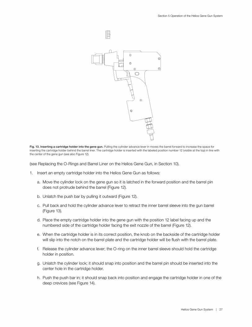
1. Insert an empty cartridge holder into the Helios Gene Gun as follows:
a. Move the cylinder lock on the gene gun so it is latched in the forward position and the barrel pin does not protrude behind the barrel (Figure 12).
b. Unlatch the push bar by pulling it outward (Figure 12).
c. Pull back and hold the cylinder advance lever to retract the inner barrel sleeve into the gun barrel (Figure 13).
d. Place the empty cartridge holder into the gene gun with the position 12 label facing up and the numbered side of the cartridge holder facing the exit nozzle of the barrel (Figure 12).
e. When the cartridge holder is in its correct position, the knob on the backside of the cartridge holder will slip into the notch on the barrel plate and the cartridge holder will be flush with the barrel plate.
f. Release the cylinder advance lever; the O-ring on the inner barrel sleeve should hold the cartridge holder in position.
g. Unlatch the cylinder lock; it should snap into position and the barrel pin should be inserted into the center hole in the cartridge holder.
h. Push the push bar in; it should snap back into position and engage the cartridge holder in one of the deep crevices (see Figure 14).
Fig. 13. Inserting a cartridge holder into the gene gun. Pulling the cylinder advance lever in moves the barrel forward to increase the space for inserting the cartridge holder behind the barrel liner. The cartridge holder is inserted with the labeled position number 12 (visible at the top) in line with the center of the gene gun (see also Figure 12).

Section 5 Operation of the Helios Gene Gun System
28 | Helios Gene Gun System
Fig. 14. Correct assembly of the cartridge holder in the gene gun in preparation for discharge. Releasing the cylinder advance lever moves the barrel liner backward, bringing the O-ring on the back of the liner in contact with the cartridge holder. Releasing the cylinder lock inserts the locking pin into the center hole in the cartridge holder.
Fig. 15. LED display of the Helios Gene Gun. Using a pressurized system, once the cartridge holder of the gene gun is correctly inserted and engaged in postion 1, the five CHARGING lights will be sequentially illuminated. Once the unit is fully charged (~5 sec), the CHARGED light will flash. If the safety interlock is then pressed, the ARMED lights will alternately flash. If the safety interlock continues to be pressed (in this ARMED state) and the trigger button is pressed, the helium will discharge and the FIRED light will then be illuminated for one second. The process of charging and arming the gun occurs automatically after it is fired. The green battery light in the BATTERY STATUS window indicates that the battery is good.
LED display
Detail of LED display

Section 5 Operation of the Helios Gene Gun System
Helios Gene Gun System | 29
i. Push in and release the cylinder advance lever to ratchet the cartridge holder one position, bringing the first cartridge into firing position. The number 12 should be seen at the top point of the cartridge holder. The gene gun is now ready for pressurizing with helium. Note: do not wiggle the cartridge holder after the cartridge is in firing position. The Helios Gene Gun has a self-centering mechanism which places the cartridge in the proper position for firing.
2. Set up the Helios Gene Gun and connect to a helium source as described in Connecting the Helios Gene Gun to a Helium Source, in Section 4. Refer to Identification of System Components and Controls, in Section 3 for identification of controls on the gene gun.
3. Start the flow of helium as follows: (Note: If a continous gas leak is observed after opening either the cylinder valve or the regulator adjustment screw, close the appropriate valve and check the tightness of the fitting. Contact Bio-Rad if a system leak persists.)
a. Close the helium pressure regulator by turning the regulator adjustment screw counterclockwise until the adjusting spring pressure is released and the screw moves without resistance.
b. Release helium into the pressure regulator by slowly opening the cylinder valve on the helium tank; open the valve fully. The helium pressure in the tank is indicated on the high pressure gauge (the one closest to the cylinder). Verify that the pressure in the tank is at least as high as the desired discharge pressure.
c. Open the helium pressure regulator using the regulator adjustment screw and set the discharge pressure to the desired setting (100–600 psi). The pressure to the system is indicated by the low pressure gauge on the regulator. Do not set the discharge pressure above 600 psi; the helium regulator has an over-pressure relief valve that will vent the system at 700 ± 50 psi. Additionally, the regulator is self-venting: turning the the regulator adjustment screw counterclockwise will reduce pressure to the system.
4. Put on hearing and eye protection, point the device away from any bystanders, and depress the trigger 2–3 times to discharge the device as described below. If this step is performed without a cylinder in place, the O-rings may be blown out.
Fig. 16. Position of hand over the safety interlock switch in preparation for firing.

Section 5 Operation of the Helios Gene Gun System
30 | Helios Gene Gun System
a. For right handed users (see Figure 16): Engage the safety interlock switch by pushing in with the thumb. Push the firing trigger with the index finger to discharge the cartridge.
b. For left handed users: Engage the safety interlock switch by pushing it in with the lower part of the index finger. Push the firing trigger with the index finger to discharge the cartridge.
5. Removing the cartridge holder from the Helios Gene Gun is accomplished as follows:
a. Move the cylinder lock on the gene gun forward and to the right so it is latched and the barrel pin does not protrude behind the barrel (Figure 12).
b. Unlatch the push bar by pulling it outward.
c. Pull back and hold the cylinder advance lever to retract the inner barrel sleeve into the gun barrel (Figure 13).
d. Pull the cartridge holder up and out of the gene gun. The gun will turn-off after 3 min.
Notes: (1) The firing trigger is functional only while the safety interlock switch is pushed in. The safety interlock switch activates the trigger button for 30 sec; if the gene gun is not fired within the 30 sec period, the safety interlock switch must be released, then pressed again to reactivate it. (2) After firing the gun, there is a 5 sec delay before the gun may be fired again. (3) Advance the cartridge holder by squeezing the cylinder advance lever between each shot.
Loading Cartridges into the Helios Gene Gun
Each cartridge holder has slots for 12 cartridges. Each slot is numbered along the edge of the cartridge holder, as seen when loading. The numbers correspond to the firing order when the cartridge holder is properly positioned in the gene gun. The cartridge holder should be loaded with cartridges beginning with position 1, then clockwise through position 12 (see Figure 17). Note, however, that the cartridge that is in firing position is at the bottom of the cartridge holder when it is inserted in the gene gun. Therefore, the cartridge in firing position will not be visible to the user but will be indicated by the number at the top of cartridge holder and visible along the cartridge rim.
Fig. 17. Loading cartridges into the cartridge holder. Numbers on the outer rim indicate sample number when delivered by the gene gun.
Cartridge holder
Cartridges
Sample numbers (loading sample)

Section 5 Operation of the Helios Gene Gun System
Helios Gene Gun System | 31
1. Place the cartridge holder on a flat surface with the numbered edge facing up.
2. Starting with position 1, load up to 12 cartridges into the cartridge holder (Figure 17). We recommend loading only one type of DNA per cylinder to avoid possible confusion.
3. Invert the cartridge holder and push the cartridges against a flat surface so that they are flush with the numbered side of the cylinder.
4. Insert the loaded cartridge holder into the Helios Gene Gun as described above. When the LED on the back of the gene gun indicates that the first cartridge is in firing position (Figure 15) the device is ready to deliver DNA.
DNA delivery to target tissue (see Section 6 for suggestions on preparing mammalian target cells)
1. Touch the target area with the spacer so that the spacer is flush and the gene gun is perpendicular to the target surface. Activate the safety interlock switch and press the trigger button to deliver the DNA/microcarriers to the target.
2. Ratchet to the next cartridge by pulling in and releasing the cylinder advance lever. After approximately 5 sec, the gene gun is ready to deliver the next cartridge.
3. After all tubes have been discharged, remove the cartridge holder as described below.
Removing Used Cartridges, Depressurization, and Shutdown
Materials
■ Cartridge extractor tool (supplied)
Removing Cartridges from the Cartridge Holder
1. Hold the cartridge holder containing the cartridges to be extracted with the back side (the side with the knob in the center) facing up.
2. Insert the long prong of the Cartridge Extractor Tool into one of the bores of the cartridge holder; turn the Cartridge Extractor Tool until all of the prongs mesh with the bores in the cartridge holder.
3. Push the prongs of the tool into the cartridge holder until the cartridges are ejected.
Depressurizing and Shutting Down the Helios Gene Gun
1. After discharging the last cartridge, turn off the helium pressure to the system by closing the valve on the helium tank.
2. Turn the regulator valve counterclockwise until both the high and low pressure gauges on the helium regulator register 0 psi. Several increase/decrease adjustments on the regulator may be necessary. Listen for venting to ensure complete depressurization. The system is now depressurized and can be safely disassembled.
3. Disconnect the helium hose from the regulator by pulling the sleeve on the Swagelok Quick-Connect Coupling toward the helium hose and pulling the fittings apart.
4. Disconnect the helium hose from the gene gun by pulling the sleeve on the Swagelok Quick-Connect Coupling toward the gene gun and pulling the fitting apart. (Warning: For safety, do not leave the Helios Gene Gun unattended while attached to the helium regulator.)

Section 6 Preparation of Mammalian Cell Targets
32 | Helios Gene Gun System
Section 6 Preparation of Mammalian Cell Targets
Time Considerations: Setting up the device requires no more than 5 min, while the delivery process requires approximately 30–60 sec per cell target. If necessary, sterilize parts as described in Cleaning and Sterilizing the Helios Gene Gun, in Section 10, before starting.
In Vitro Delivery to Adherent Cells
Method 1
Day 1
1. Trypsinize cells from flasks. Resuspend the cells in tissue culture media at a density so that inoculating 2 ml into a 35 mm tissue culture plate will produce a monolayer 60–80% confluent after 24 hr.
2. Inoculate 2 ml of cells into 35 mm tissue culture plates.
3. Incubate overnight under the appropriate conditions.
Day 2
1. Prepare the Helios Gene Gun for operation as described in Particle Delivery Using the Helios Gene Gun, in Section 5.
2. Immediately prior to DNA delivery, aspirate the media from the dish.
3. Hold the dish perpendicular to the spacer and touch the end of the plastic spacer (if the spacer is sterile), or as close as possible to the target, and discharge the gene gun (Figure 18).
4. Add 1.5–2 ml of media to the plate and return to the incubator.
Method 2
1. Trypsinize cells from flasks. Resuspend the cells in tissue culture media buffered with 25 mM HEPES (pH 7.3) and count viable cells.
2. Dilute cells to 2 x 10⁶ cells/ml.
3. Using a sterile pipet tip, spread 100 µl of the cell suspension in a 1.5 cm diameter circle in the center of a 35 mm dish, being careful not to break the meniscus. It is useful to draw a 1.5 cm diameter circle on an index card to use as a template under the culture dish.
4. Allow the plates to incubate undisturbed for 30 min to permit the cells to attach.
5. Gently add 1 ml of media to each plate and place in the incubator. Incubate the cells for at least 4 hr.

Section 6 Preparation of Mammalian Cell Targets
Helios Gene Gun System | 33
6. Prepare the Helios Gene Gun for operation as described in Particle Delivery Using the Helios Gene Gun, in Section 5.
Fig. 18. Correct placement of the Gene Gun when transfecting cells in vitro (photo courtesy of Auragen, Inc.).
7. Immediately prior to DNA delivery, aspirate the media from the dish.
8. Hold the dish perpendicular to the spacer and touch the end of the plastic spacer (if the spacer is sterile), or as close as possible to the target, and discharge the gene gun (Figure 18).
9. Add 1.5–2 ml of media to the plate and return to the incubator.
In Vitro Delivery to Suspension Cultures
Method 1
1. Prepare the Helios Gene Gun for operation as described in Particle Delivery Using the Helios Gene Gun, in Section 5.
2. Transfer the cells to a centrifuge tube and pellet in a table top centrifuge for 5 min at 250 x g.
3. Resuspend the cells in tissue culture media containing 25 mM HEPES (pH 7.3) at a concentration of 5 x 10⁷ cells/ml.
4. Inoculate 20 µl (1 x 10⁶ cells) of the cell suspension into a 1.5 cm circle in the center of a 35 mm dish. It is useful to draw a 1.5 cm diameter circle on an index card for use as a template under the culture dish.

Section 6 Preparation of Mammalian Cell Targets
34 | Helios Gene Gun System
5. Hold the dish perpendicular to the spacer and touch the end of the plastic spacer (if the spacer is sterile), or as close as possible to the target, and discharge the Gene Gun (Figure 18).
6. Add 1.5–2 ml of media to the plate and return to the incubator.
Method 2
1. Prepare 35 mm tissue culture plates with Cell-Tak (Thermo Fisher Scientific, Waltham, MA) using manufacturer’s instructions.
2. Transfer cells to a centrifuge tube and pellet in a table top centrifuge for 5 min at 250 x g.
3. Resuspend cells in tissue culture media without serum at a concentration such that inoculating 2 ml of cells into the 35 mm tissue culture plates treated with Cell-Tak will produce a monolayer 60–80% confluent.
4. Inoculate 2 ml of cells into 35 mm tissue culture plates.
5. Incubate 30 min to 4 hr under the appropriate conditions.
6. Prepare the Helios Gene Gun for operation as described in Particle Delivery Using the Helios Gene Gun, in Section 5.
7. Immediately prior to DNA delivery, aspirate the media from the dish.
8. Hold the dish perpendicular to the spacer and touch the end of the plastic spacer (if the spacer is sterile), or as close as possible to the target, and discharge the Gene Gun (Figure 18).
9. Add 1.5–2 ml of media to the plate and return to the incubator.

Section 6 Preparation of Mammalian Cell Targets
Helios Gene Gun System | 35
In Vivo Delivery to Epidermis
Animal Preparation
1. Anesthetize the animal if necessary for safe handling.
2. Clip fur as closely as possible over the desired target area using Oster clippers with a #40 surgical blade and brush or vacuum fur off.
3. (Optional) After clipping, a commercial depilatory such as Nair can be used to completely remove the animal’s fur. This treatment removes the stratum corneum from the skin, completely exposing the epidermis. Carefully rinse the skin with warm water following depilatory treatment.
4. If the target site is wet or dirty, clean and dry with 70% ethanol.
Helios Gene Gun Operation
1. Prepare the Helios Gene Gun for operation as described in Section 5.3.
2. Hold the spacer directly against the target site (Figure 19) and discharge the device. (Discomfort following Helios Gene Gun bombardment of the skin is minimal. No apparent macroscopic disruption of the skin, external bleeding or hematoma should be observed. Some animals may show transient erythema or inflammation at the treatment site.)
Fig. 19. In vivo bombardment of murine epidermis (photo courtesy of Auragen, Inc.).

Section 7 Optimization of Gene Gun Parameters
36 | Helios Gene Gun System
Section 7 Optimization of Gene Gun Parameters
OverviewThe flexibility of the particle delivery system allows fine-tuning of experimental parameters; however, it is necessary for each laboratory to determine the optimal parameters for their particular instrument and in vivo or cell culture system. Any quantitative assay may be used to determine the optimum combination of critical parameters for the particular biological system under investigation. Important parameters to evaluate include the helium pressure, the PVP concentration, the microcarrier loading quantities (MLQ), and the DNA loading ratio (DLR). It should be noted that absolute transgene expression levels are only a part of the processes leading to immune or other biological responses, thus, each researcher must identify those parameters that result in the appropriate level, location, and duration of transgene expression following particle-mediated delivery. The representative results shown below reveal a commonly observed and useful trait of the Helios Gene Gun: a broad, bell shaped distribution of effective delivery parameters.
Scientists are advised to optimize bombardment parameters for their particular gene gun and biological system. The experimental approach which appears to be most effective in determining the optimum bombardment conditions is the following.
Expt 1: Optimize helium pressure: Coat plasmid onto gold particles at 2 µg plasmid/mg gold. Prepare tubes with 0.05 mg/ml PVP and 500 µg gold/shot (1 µg plasmid/shot). Bombard the target tissue at 50, 100, 200, and 400 psi helium to determine the optimum helium pressure.
Expt 2: Optimize PVP concentration: Use gold particles coated with 2 µg plasmid/mg gold as in Experiment 1. Prepare tubes with 0, 0.05, and 0.1 mg/ml PVP. Bombard the target tissue using the optimum helium pressure determined in Experiment 1.
Expt 3: Optimize MLQ: Coat plasmid onto gold particles at 2 µg, 4 µg, and 8 µg plasmid/mg gold; prepare tubes with each DNA/gold sample at 1 µg plasmid/shot (this is 500 µg gold/shot, 250 µg gold/shot, and 125 µg gold/shot, respectively), and containing the optimum amount of PVP determined in Experiment 2. Bombard the target tissue at the optimum helium pressure determined in Experiment 1 or 2.
Expt 4: Optimize DLR: The lowest amount of DNA that has been found to give a detectable level of gene expression is 1 ng of plasmid, but this is dependent on the vector, the target, and the assay system. For most experimental systems, bombardment with 1 µg of plasmid produces near maximal expression. Increasing the amount of plasmid per bombardment does not result in a proportional increase in gene expression. However, bombardment with higher amounts of DNA may be important when using several expression vectors. To verify the optimum amount of plasmid per bombardment precipitate different amounts of plasmid onto gold particles – depending on how extensive a study desired, this may be as simple as a single two-fold dilution to multiple dilutions using between 1 ng and 5 µg of plasmid per bombardment; the other bombardment parameters should be as determined in the previous experiments.
For example, Figure 20 shows a test of discharge pressure on transient gene expression, in mouse skin transfected in vivo as described in In Vivo Delivery to Epidermis, in Section 6. Optimum pressure was determined to occur at 200 psi. This pressure resulted in adequate penetration of the particles without excessive tissue damage, and deposition of the majority of the particles in the epithelial layer rather than the relatively acellular underlying dermal tissue.

Section 7 Optimization of Gene Gun Parameters
Helios Gene Gun System | 37
hGH
act
ivity
, ng/
ml
80
60
40
20
00 100 200 400
Helium pressure, psi
Fig. 20. Luciferase expression in mouse skin transfected in vivo using the Helios Gene Gun. Skin homogenates were assayed 24 hours posttransfection.
Luci
fera
se a
ctiv
ity (r
elat
ive
light
uni
ts x
10
-8)
3.0
2.5
2.0
1.5
1.0
0.5
0 1.0 0.5 0.25 0.12 0.06
mg gold per cartridge
Fig. 21. Effect of the amount of accelerated gold particles on in vitro expression levels. Suspension cultures of CHO cells were bombarded as described in Section 6.2 using the Accell Gene Gun. After 18 hours, the CHO cells that had reattached to the tissue culture plate were lysed and assayed for luciferase expression.
As illustrated in Figure 21, the optimum MLQ is determined by adjusting the concentration of the DNA/microcarrier suspension loaded into the GoldCoat Tubing. For suspension cells, higher MLQs (0.5–1.0 mg gold/cartridge) are often needed due to the high cell concentrations in the aqueous cell smear. Adherent cell monolayers and intact tissues may require reduced MLQs (0.06–0.25 mg gold/cartridge) to minimize tissue damage while maximizing transfection.

Section 7 Optimization of Gene Gun Parameters
38 | Helios Gene Gun System
Another variable parameter, DNA loading rate (DLR), is determined by varying the concentration of DNA precipitated on to the gold particles. Table 3 shows DNA dosage results for transfection of CHO cells using the method described in In Vitro Delivery to Suspension Cultures, in Section 6. Secretion of murine granulocyte macrophage colony stimulating factor (mGM-CSF) was greater at higher DNA dosages. Similar results have been found for several in vivo and in vitro systems, with maximal expression observed for 1–5 µg DNA/mg gold particles. At dosages above ~5 µg/mg, the DNA and gold can form a single clump which is unsuitable for cartridge preparation.
Table 3. Effect of DNA concentration on mGM-CSF expression in CHO cells.*
DNA loading rate** Expression,*** ng/106 cells
2.5 5150.25 2390.025 250.0025 0.9
* CHO cells were transfected as suspension cultures using the Accell Gene Gun.
** Irrelevant plasmid DNA was added to each preparation to bring the total amount of DNA precipitated constant.
*** mGM-CSF in the media was assayed 24 hours postbombardment by ELISA as described by Mahvi et al. (1996).
Parameters for In Vitro DeliveryThe following conditions have been found to be effective for transformation of mammalian cell lines. However, each laboratory should determine the optimum parameters for their particular application. (See previous section.)
Table 4. Suggested starting conditions for in vivo transformation of tissue culture cells using the Helios Gene Gun.
Parameter Conditions
Helium pressure 50–200 psiPVP 0–0.015 mg/mlMLQ 0.125–0.5 mg/tubeMicrocarriers 1.0 or 1.6 µ goldDLR 0.5–2.5 µg DNA/mg gold (0.06–1.25 µg DNA/cartridge)

Section 8 Troubleshooting
Helios Gene Gun System | 39
Parameters for In Vivo DeliveryThe following are suggested starting conditions for optimizing DNA delivery to the skin of various species. Each laboratory should determine the optimum parameters for their particular application (see Overview in Section 7 and Table 5). Bombardment conditions are those used in references cited in Section 10, using the Accell Gene Gun. Use this information as a starting point when optimizing bombardment conditions with the Helios Gene Gun. Lower helium pressures should be tested early in the optimization process.
Table 5. Examples of parameters for delivery into skin of various species
Species Site MLQ, mg/target DLR, µg/mg PVP, mg/ml psi
Dog9 Dorsum 0.5 1–2 0.1 300Monkey7, 8, 9 Abdomen 0.25 2 0–0.05 300–400Mouse17, 19 Abdomen* 0.25–0.5 1–2.5 0–0.1 300–500
Pig7, 8, 10 Inner thigh (clipping not necessary)
0.25–0.5 0.5–2.5 0.05 500
Rabbit27 Back 0.5 1–2 None 350–400
* Do not use a depilatory agent to remove the fur (Section 6.3, step 3)
Section 8 Troubleshooting
DNA/Microcarrier PreparationProblem Microcarriers agglomerate after coating with DNA.
Possible solutions Lower DNA loading rate.
Cartridge PreparationProblem Gold does not spread evenly in the GoldCoat Tubing
(rings, clumps, uncoated sections, streaks).
Possible solutions Eliminate any potential sources of water in the tube and in the final DNA/microcarrier preparation.
Rewash remaining microcarrier prep 2–3 times using a fresh bottle of 100% ethanol.
Flush GoldCoat Tubing with nitrogen gas for 15 min prior to loading with DNA/gold microcarrier solution.
If using PVP, make a new stock of PVP in ethanol using a fresh bottle of alcohol.
Resuspend gold/DNA pellet prior to first ethanol wash.
After drawing off the ethanol, quickly turn the GoldCoat Tubing with your fingers prior to rotating.

Section 8 Troubleshooting
40 | Helios Gene Gun System
Helios Gene Gun OperationProblem LED display not lit.
Possible solutions Battery missing or discharged; replace battery.
Problem Device does not fire (helium burst does not occur).
Possible solutions Check that the helium tank and regulator knobs are opened and that there is sufficient helium in the tank.
Check that the helium hose is properly connected.
Check that the battery is good and that the LED display indicates that a cartridge is in firing position.
Problem The first cartridge fires well but gold is not delivered in subsequent cartridges.
Possible solutions Check that the O-rings are in place and are not worn (see Replacing the O-Rings and Barrel Liner on the Helios Gene Gun, in Section 10). Check that the cartridge holder is properly positioned in the Gene Gun (see Preparation of System Components Prior to Bombardment, in Section 5).
Problem The device fires but gold is not delivered.
Possible solutions Check that the O-rings are in place and are not worn.
Check that the barrel liner is tight (see Replacing the O-Rings and Barrel Liner on the Helios Gene Gun, Section 10).
Check that the cartridge holder is properly positioned in the Gene Gun (see Preparation of System Components Prior to Bombardment, in Section 5).
Helium pressure is too low; increase the discharge pressure.
Cartridge preparation is bad; make new cartridges.
Too much PVP in tubes; increase helium pressure or reduce PVP concentration.
Problem A discharge of helium occurs from the gun after first turning on the helium regulator and pressurizing the system.
Possible solutions Open the helium regulator quickly one or two turns and pressurize the system to >100 psi. The pressure can then be readjusted to another setting. If continuous helium discharge is observed after this, contact Bio-Rad.
In Vitro and In Vivo TargetingProblem Gold does not penetrate skin or organ.
Possible solutions Check that the helium pressure has not dropped below the set delivery pressure.
Increase the PVP concentration in the cartridge preparations.
Increase the delivery pressure.
Check that the gold has been discharged from the cartridge after firing.
Use larger gold particles.

Section 9 Product Information
Helios Gene Gun System | 41
Problem Poor or no expression.
Possible solutions Make sure DNA is resuspended in TE or distilled water, not saline.
Check that DNA has been precipitated onto the microcarriers (see Quantification of DNA in Cartridges, in Section 10).
Problem Attached cells are lifting off the center of the plate after delivery of gold particles, or there is a dead zone in the center of the target.
Possible solutions Lower the helium pressure and/or lower the microcarrier loading rate.
Problem Contamination of the cell culture.
Possible solution Wipe the end of the barrel with ethanol or dilute bleach.
Section 9 Product Information
Helios Gene Gun SystemThe catalog numbers for the two Helios Gene Gun Systems (100/120 V and 220/240 V) and component descriptions are as follows:
Catalog # Description
1652431 Helios Gene Gun System, 100/120 V includes 1652411 Helios Gene Gun Kit, that includes Gene Gun Unit, 1
1652416 O-rings, Helios Gene Gun, 51652417 Barrel Liner, 51652426 Cartridge Holder, white, 51652435 Cartridge Extractor Tool, 11652436 Battery, 9 V, 1
1652412 Helium Hose Assembly, with Swagelock Quick-Connect Fittings, 1 1652413 Helium Regulator, CGA 580 female fitting, with pressure relief
valve. Maximum pressure 2,600 psi., 11652418 Tubing Prep Station, includes Tubing Prep Station, 100/120 V, 1 tubing support cylinder, 1 power cord, O-rings, 5 Tubing Prep
Units (1652419), 12 ft nitrogen regulator hose (Nalgene), two 3/16” barb to male luer fittings, nitrogen flowmeter fitting, two 1/8” barb-to-male luer fittings, one 5/64" Allen wrench, one 10cc syringe holder
165-2421 Macro-Prep DEAE Resin, 500 ml165-2422 Macro-Prep DEAE Resin, 5 L165-2424 Macro-Prep DEAE Resin, 10 L1652432 Macro-Prep CM Resin, 25 ml7326100 Quantum Prep Plasmid Miniprep Kit, 100 preps7326120 Quantum Prep Plasmid Miniprep Kit, 20 preps

Section 9 Product Information
42 | Helios Gene Gun System
Spare PartsCatalog # Description
9204987 Door, Battery Compartment, gene gun 9204988 Cover, Molded Nose9204995 External Barrel Handle9101503 Screw, 6-32 x 1/4, FH9100453 Thumbscrew, nylon, 1/4 x 20 x 1” 9100620 Thumbscrew, nylon, 1/4 x 20 x 1/2”8004478 Assembly, C-shaft (tube support assembly)9009712 Fuse, 5 x 20 mm, 0.125 A9007296 Fuse, 5 x 20 mm, 0.25 A9400359 Sealant, pipe9109223 Fitting, elbow, female luer9301185 Kit, helium regulator, soft goods (O-rings), version A 1652436 9 V Battery1652423 Razor Blades, 10 1652416 O-rings, gene gun 1652417 Barrel Liner1652426 Cartridge Holder
Gene Gun Specifications
Specifications
PhysicalDimensions Approximately 8 x 10"Weight 3.15 lbConstruction Super epoxy or polycarbonateCylinder AcetalBarrel liner RytonO-rings Viton
ElectricalMaximum current 10 mA peakVoltage input 9 V DC alkaline battery, replaceableBattery life 1,000 discharges in continuous use
FunctionalInput pressure 600 psi maximum heliumRegulator relief pressure 700 ± 35 psi at regulator assemblyRegulator adjustment 800 psi limit maximumDischarges 12 per cylinder revolutionIndexing Manual
EnvironmentalOperating 50–90°F (10–32°C) temp
30–80% humidityStorage 32–140°F (0–60°C) temp
10–90 % humidity

Section 10 Appendices
Helios Gene Gun System | 43
Tubing Prep Station Specifications
Specifications
PhysicalDimensions Approximately 33.5 x 4"Weight 11.2 lbConstruction Aluminum and acrylic
ElectricalMaximum current 62 mA/125 mA peakVoltage input 220–240 V AC/100–120 V ACInput frequency 50/60 Hz
FunctionalInput pressure 30 psi N2
Relief pressure 30 ± 1.5 psi at regulator assemblyRegulator adjustment TDB psi limit maximumSpeed 30 RPM nominalTubing fill manual
EnvironmentalOperating 50–90°F (10–32°C) temp
30–80 % humidityStorage 32–140°F (0–60°C) temp
10–90 % humidity
Section 10 Appendices
Precipitation of RNA onto microcarriersPrimary RNA transcripts and mRNA may be effectively delivered in vivo and in vitro using the Helios Gene Gun System (Qiu et al., 1996). The procedure is similar to that for DNA, but the precipitation step is performed with ammonium acetate and 2-propanol.
Materials
In addition to those identified in Preparation of System Components Prior to Bombardment, Section 5:
■ Purified RNA preparation (for example, capped, polyadenylated, or oligo dT-selected mRNA).
■ 5 M ammonium acetate
■ 2-propanol
Experiments involving RNA require careful technique to prevent RNA degradation.
Procedure (sufficient for one length of GoldCoat Tubing):
1. In a 1.5 ml microcentrifuge tube weigh out 25 mg gold particles.
2. To measured gold add aqueous solution of mRNA preparation. The ratios of RNA to gold used are similar to those used for DNA (1–15 µg RNA/mg particles).
3. Add 1/10 volume of 5 M ammonium acetate and 2 volumes of 2-propanol, mix by vortexing. Place the microfuge tube at -20°C for 1 hour.
4. Proceed with Section 5.2, steps 9–12.

Section 10 Appendices
44 | Helios Gene Gun System
Replacing the O-Rings and Barrel Liner on the Helios Gene GunThe Helios Gene Gun has three user-serviceable parts: the barrel liner and two O-rings (Figure 22). The barrel liner screws into the barrel of the Gene Gun. It is a molded plastic piece with the correct shape to permit optimum spread and penetration of the microcarriers at the target site. It may be autoclaved between experiments or replaced.
Fig. 22. Location of barrel liner and O-rings in the gene gun. The barrel (cover) is removed for visual clarity but is not required for barrel liner removal/insertion.
To remove the barrel liner:
Hold the exposed part of the barrel liner (the spacer) and turn counterclockwise 4–5 turns (see Figure 5).
To insert the barrel liner:
1. Remove the cartridge holder from the gene gun.
2. Place the barrel liner into the gene gun and turn clockwise until the threads just bind. Do not overtighten.
The O-rings function to keep the helium from expanding around the tube in the firing position in the cartridge holder. One O-ring is inserted at the end of the barrel liner that makes contact with the cartridge holder; the other O-ring surrounds the exit port of the main valve. Both O-rings fit in grooves with center supports.
To replace the O-ring on the end of the barrel liner:
1. Remove the barrel liner.
2. Remove the old O-ring from the barrel liner.
3. Place a new O-ring in the groove and press it in gently. Do not use grease or adhesive.
To replace the O-ring around the exit port of the main valve:
1. Using a pin or syringe needle, poke the O-ring from the edge to pop it out. Be careful not to scratch the surface of the valve.
2. Place a new O-ring in the groove and press it in gently. Do not use grease or adhesive.
Barrel liner
O-rings

Section 10 Appendices
Helios Gene Gun System | 45
Replacement of Razor Blade on and Disassembly of the Tubing CutterThe cutting edge of the tubing cutter is a standard single-edge razor blade. Because cutting is done only on one end of the blade at once, it can be rotated after the first end becomes dull. The first sign of a dull blade will be incomplete cutting of two adjacent cartridges. Front refers to the side of the tubing cutter with the tubing channels. Right, left, and back refer to the sides of the tubing cutter when the user faces the front of the unit (see Figure 23).
1. Loosen the red locking knob on the back of the tubing cutter by turning it approximately one full turn until the lock block on the rear of the cutting arm is free to move.
2. Move the lock block to the right to free the razor blade retaining screw on the right side.
3. Lift up on the right side of the razor blade until it can be lifted free of the tubing cutter.
Replacing the O-Ring on the Tubing Prep StationThe Tubing Prep Station has two user-serviceable parts: O-rings at the end of the tubing support cylinder nearest the motor. If the O-rings are worn, nitrogen may leak around them and the amount of nitrogen indicated on the flowmeter will not be passing through the tubing. Under normal use, the lifetime of the O-rings should be longer than 1 year. The O-rings may be changed as follows (see Figure 23):
1. Remove the tubing support cylinder by pushing it to the right to contract the spring on the support bar, then raise the left side up and away from the base of the unit.
2. The outer O-ring should be located in the slot at the end of the tubing support cylinder, although it may remain in the support on the motor housing. It may be removed with a fingernail or a blunt object, such as a toothpick. If worn, replace the O-ring with a new one.
3. The inner O-ring is at the end of the tubing support cylinder next to the stem. To replace it, remove the stainless steel stem at the end of the tubing support cylinder by loosening the hex nut on the lower surface of the tubing support cylinder one-eighth turn using a 5/64" Allen wrench. The stem and spur gear can be pulled out of the tubing support cylinder. Remove the O-ring from the slot in the stem with a fingernail or blunt object and replace if worn. Insert the stem into the end of the tubing support cylinder; press gently on the end to hold the O-ring in place and tighten the hex nut. Replace the tubing support cylinder in the base of the Tubing Prep Station.
Fig. 23. Replacing the O-rings on the Tubing Prep Station. The O-rings are located in the tubing support cylinder on the side next to the motor housing. One O-ring (A) fits into a slot on the outside edge of the stem at the end of the tubing support cylinder. The other O-ring (B) is on the inside surface of the stem and can be removed only after loosening the hex nut and removing the stem from the tubing support cylinder.
Stem
Hex nutSpur gear
O-ringBO-ringA

Section 10 Appendices
46 | Helios Gene Gun System
4. Insert a new blade (or rotate the old blade 180˚) by inserting the notch on the left side of the blade into the retaining screw on the left side of the cutting arm.
5. Hold the razor blade so that the notch on the blade is next to retaining screw on the right side of the cutting arm. Using the red locking knob, move the retaining screw into the notch in the razor blade and turn the locking knob clockwise to lock the razor blade in place.
Fig. 24. The tubing cutter.
The tubing cutter may be disassembled for cleaning. For safety, remove the razor blade prior to disassembly.
1. Place the tubing cutter in front of you on a solid surface so that you are facing the front of the unit.
2. Hold the base between the thumb and index finger of your right hand. At the same time, push the left side of the tubing cutter arm to the right with the index finger of your left hand. This will disengage the arm from the pivot pin on the left side of the base and from the retaining pin on the right side of the base — the tension on the spring will push the arm up.
3. Raise the arm up and away from the base.
4. The tubing cutter may be cleaned with soap and water and/or with 70% or 100% ethanol. Do not autoclave the tubing cutter.
5. Assembly is the reverse of disassembly. With the spring in place, lay the cutting arm, correctly oriented, on top of the base. With the index and middle fingers of your left hand, press down on the left side of the arm to compress the spring about 3/16”. Simultaneously, with the index and middle fingers of your right hand, push the arm to the left to engage the cutting arm under the stainless steel pivot pin on the left side of the base and under the stainless steel retaining pin on the right side of the base.
Retaining pin
Lock block
Locking knob
Pivot pin
Base
Retaining screw
Tubing channels
Razor blade
Retaining screw
Arm

Section 10 Appendices
Helios Gene Gun System | 47
Cleaning and Sterilizing the Helios Gene GunIn situations where sterility is a concern, such as in vitro targeting, the spacer may be brought as close to the target surface as possible without actually touching the surface. Alternatively, by wiping down the end of the barrel liner with 70% alcohol or dilute bleach followed by a rinse with distilled water, the spacer may touch the target surface.
It is possible to sterilize certain parts of the instrument by autoclaving. The following parts may be autoclaved:
■ Barrel liner
■ Cartridge holder
■ Cartridge extractor tool
The following items should never be autoclaved or imersed in liquid:
■ Gene gun
■ Tubing Prep Station
■ Helium regulator
These parts, along with the tubing cutter, may be cleaned using a cloth and a mild soap solution. Do not autoclave the tubing cutter.
Although GoldCoat Tubing may be autoclaved, this is not recommended since it may result in water condensation inside the tubing, which will lead to poor-quality cartridges.
Testing Cartridges for Microcarrier Penetration and Density (Optional)Either of these procedures may be used to roughly determine the quality of the cartridge preparation. These procedures give only qualitative results and are therefore best when they can be compared against cartridges that have been shown to produce positive results in a biological assay. The results are very dependent on the size of the microcarriers and on the amount of PVP used in loading the microcarriers into the GoldCoat Tubing.
Fig. 25. Representative bombardment showing penetration of 1.6 µm gold particles into Parafilm Laboratory Film at (left to right) 100, 200, 300, 400, 500, and 600 psi using the Helios Gene Gun.

Section 10 Appendices
48 | Helios Gene Gun System
Discharge into Parafilm
Materials
■ Parafilm Laboratory Film (Bemis Company, Inc., Neenah, WI)
■ Glass plate
Procedure
1. Cut a piece of Parafilm from the roll; a 1" length is required for each cartridge to be assayed.
2. Smooth and press the Parafilm laboratory film (waxy surface down) onto the glass plate. Fold the edges around the sides then peel away the protective paper.
3. Connect the helium regulator, helium hose, and Helios Gene Gun as described in Connecting the Helios Gene Gun to a Helium Source, in Section 4.
4. Pressurize the system as described in Particle Delivery Using the Helios Gene Gun, in Section 5.
5. Discharge a cartridge at the test psi into a strip of Parafilm Laboratory Film. At this point, one can roughly determine the quality of the microcarrier preps by examining the pattern of gold particles. When examining the resulting pattern, it should appear circular with a dark center (Figure 25). The discharged cartridges should be completely empty.
Spot darkness Proportional to particle penetration
Spot width Proportional to particle spread
Spot shape Uniformity of shot
Discharge into 3% Water Agar
Materials
■ Slides, coverslips, and mounting solution
■ Microscope with 10x eyepiece micrometer
■ 3% water agar in 60 mm petri dishes
Procedure
1. Discharge a cartridge at the test psi into 3% water agar. At this point, one can roughly determine the quality of the microcarrier preps by examining the pattern of gold particles. When examining the resulting pattern, it should appear circular with a dark center. The discharged cartridges should be completely empty. Additionally, one can also examine microcarrier depth penetration into the water agar microscopically. Cut a thin slice approximately 0.5 cm long through the center of the agar target. Mount the slice onto a slide with mounting solution and a coverslip and analyze for microcarrier depth and concentration.
2. A band of microcarriers will be visible in the agar with increasing particle sizes at increased depths. The researcher will be able to determine areas of high, medium, and low microcarrier density in each slice (Figure 26).

Section 10 Appendices
Helios Gene Gun System | 49
3. To determine the depth of penetration, align the 0 of an eyepiece micrometer at the upper surface of the agar and measure the distance to the arbitrary floor of the microcarrier distribution. This value is the microcarrier depth.
The distribution pattern of the microcarriers is bell-curve shaped with respect to depth and area. The highest microcarrier density is concentrated at the center of the shot and at the surface of the target site. For this reason, in order to obtain a truly representative microcarrier distribution cross section, be careful to examine the center and full length of your target site.
Fig. 26. Representative cross-section showing penetration of gold particles into water agar after discharge with a helium pulse.

Section 10 Appendices
50 | Helios Gene Gun System
Quantification of DNA in CartridgesThis procedure can be used for estimating the amount of DNA in cartridges when 0.5 µg or more of DNA has been loaded per tube.
Materials
■ 10 mM Tris, pH 8.0, 1 mM EDTA
■ 1,000 µ micropipettor and tips
■ Ultrasonic cleaner
■ UV spectrophotometer
■ Vortexer
■ Quartz cuvettes
■ Microfuge
Procedure
1. Place five 0.5" cartridges in a microcentrifuge tube and add 500 µl of TE.
2. Sonicate and/or vortex to dislodge gold and solubilize the DNA. Spin for 5 min in a microfuge to pellet gold.
3. On a spectrophotometer, determine the A260 by reading against a TE blank. If 100% of the DNA were precipitated onto the microcarriers, the A260 readings should be as follows:
Plasmid/Cartridge, µg A260
0.5 0.11.0 0.22.0 0.4
4. DNA sample may also be analyzed by restriction enzyme digestion and analysis by agarose gel electrophoresis.

Section 10 Appendices
Helios Gene Gun System | 51
ReferencesAlbertini MR, et al. (1996). Dual expression of human leukocyte antigen molecules and the B7-1 costimulatory molecule (CD80) on human melanoma cells after particle-mediated gene transfer. Cancer Gene Ther 3, 192–201.
Andree C, et al. (1994). In vivo transfer and expression of a human epidermal growth factor gene accelerates wound repair. Proc Natl Acad Sci USA 91, 12188–12192.
Armaleo D, et al. (1990). Biolistic nuclear transformation of Saccharomyces cerevisiae and other fungi. Curr Genet 17, 97-103.
Boynton JE, et al. (1988). Chloroplast transformation in Chlamydomonas with high velocity microprojectiles. Science 240, 1534–1538.
Cheng L, et al. (1993). In vivo promoter activity and transgene expression in mammalian somatic tissues evaluated by using particle bombardment. Proc Natl Acad Sci USA 90, 4455–4459.
Eisenbraun MD, et al. (1993). Examination of parameters affecting the elicitation of humoral immune responses by particle bombardment-mediated genetic immunization. DNA Cell Biol 12, 791–797.
Fynan EF, et al. (1993). DNA vaccines: protective immunizations by parenteral, mucosal, and gene-gun inoculations. Proc Natl Acad Sci USA 90, 11478–11482.
Johnston SA, et al. (1988). Mitochondrial transformation in yeast by bombardment with microprojectiles. Science 240, 1538-1541
Klein TM, et al. (1988). Transfer of foreign genes into intact maize cells with high-velocity microprojectiles. Proc Natl Acad Sci USA 85, 4305–4309.
Klein RM, et al. (1987). High-velocity microprojectiles for delivering nucleic acids into living cells. Nature 326, 70–73.
Mahvi DM, et al. (1996). Particle-mediated gene transfer of granulocyte-macrophage colony-stimulating factor cDNA to tumor cells: implications for a clinically relevant tumor vaccine. Human Gene Ther 7, 1535–1543.
McCabe DE, et al. (1988). Stable transformation of soybean (glycine max) by particle acceleration. Bio/Technology, 6, 923-926.
Qiu P, et al. (1996). Gene gun delivery of mRNA in situ results in efficient transgene expression and genetic immunization. Gene Ther 3, 262–268.
Rakhmilevich AL, et al. (1996). Gene gun-mediated skin transfection with interleukin 12 gene results in regression of established primary and metastatic murine tumors. Proc Natl Acad Sci USA 93, 6291-6296.
Reba I (1966). Applications of the Coanda Effect. Scientific American, 214, 84-92.
Shark KB, et al. (1991). Biolistic transformation of a procaryote, Bacillus megaterium. Appl Environ Microbiol 57, 480–485.
Smith FD, et al. (1992). Biolistic transformation of prokaryotes: factors that affect biolistic transformation of very small cells. J Gen Microbiol 138, 239–248.
Sun WH, et al. (1995). In vivo cytokine gene transfer by gene gun reduces tumor growth in mice. Proc Natl Acad Sci USA 92, 2889–2893.
Sundaram P, et al. (1996). Particle-mediated delivery of recombinant expression vectors to rabbit skin induces high-titered polyclonal antisera (and circumvents purification of a protein immunogen). Nuc Acids Res 24, 1375–1377.
Tang DC, et al. (1992). Genetic immunization is a simple method for eliciting an immune response. Nature 356, 152–154.
Williams RS, et al. (1991). Introduction of foreign genes into tissues of living mice by DNA-coated microprojectiles. Proc Natl Acad Sci USA 88, 2726–2730.
Yang NS, et al. (1990). In vivo and in vitro gene transfer to mammalian somatic cells by particle bombardment. Proc Natl Acad Sci USA 87, 9568–9572.
Zelenin AV, et al. (1989). Genetic transformation of mouse cultured cells with the help of high-velocity mechanical DNA injection. FEBS Lett 244, 65–67.
The instruments used in these experiments vary. Use the above information as a starting point when optimizing bombardment conditions with the Helios Gene Gun. Lower helium pressures should be tested early in the optimization process.

Section 10 Appendices
52 | Helios Gene Gun System
Quick Guide to Operation
Before the Bombardment
1. Coat microcarriers with DNA, load into tubes, and prepare cartridges prior to day of experiment.
2. Check helium supply (50 psi in excess of desired rupture pressure).
3. Clean and/or sterilize the gene gun, tube holders, and barrel liner as appropriate.
4. Connect the gene gun to a helium source.
5. Activate the gene gun: turn on the flow of helium to the desired pressure and with an empty cartridge holder in place, make 2–3 pre-shots by engaging the safety interlock and firing the trigger.
Firing the Device
1. Load cartridges into the cartridge holder and place in gene gun.
2. Prepare/position target cells for bombardment.
3. Bombard sample: engage safety interlock and press the firing trigger
After the Bombardment
1. Remove cartridge holder from gene gun.
2. Remove cartridges from cartridge holder.
3. Turn off the helium pressure to the system.
4. Turn the regulator value counterclockwise to de-ressurize the system.
5. Disconnect the helium hose and gene gun.
Go to bio-rad.com/Helios/training for additional Helios Gene Gun training and overview information, including instrument setup, microcarrier and cartridge preparation, and instrument operation.


10000118158 Ver A (M1652411) US/EG 19-0511 0819 Sig 0119
Web site bio-rad.com USA 1 800 424 6723 Australia 61 2 9914 2800 Austria 43 01 877 89019 Belgium 32 03 710 53 00 Brazil 55 11 3065 7550 Canada 1 905 364 3435 China 86 21 6169 8500 Czech Republic 36 01 459 6192 Denmark 45 04 452 10 00 Finland 35 08 980 422 00 France 33 01 479 593 00 Germany 49 089 3188 4393 Hong Kong 852 2789 3300 Hungary 36 01 459 6190 India 91 124 4029300 Israel 972 03 963 6050 Italy 39 02 49486600 Japan 81 3 6361 7000 Korea 82 2 3473 4460 Mexico 52 555 488 7670 The Netherlands 31 0 318 540 666 New Zealand 64 9 415 2280 Norway 47 0 233 841 30 Poland 36 01 459 6191 Portugal 351 21 4727717 Russia 7 495 721 14 04 Singapore 65 6415 3188 South Africa 36 01 459 6193 Spain 34 091 49 06 580 Sweden 46 08 555 127 00 Switzerland 41 0617 17 9555 Taiwan 886 2 2578 7189 Thailand 66 2 651 8311 United Arab Emirates 971 4 8187300 United Kingdom 44 01923 47 1301
Bio-Rad Laboratories, Inc.
Life ScienceGroup
BIO-RAD, HELIOS, MACRO-PREP, and QUANTUM PREP are trademarks of Bio-Rad Laboratories, Inc.
All trademarks used herein are the property of their respective owner.
Visit bio-rad.com/GeneGun for more information.


![Indoor pass by noise - UNECE · 2018. 1. 23. · noise level measured in a semi-anechoic chamber [dB (A)] 10 dB. Kramer and ald, Comparison of pass-by noise from real track and simulated](https://img.pdfslide.net/doc/110x75/609f06d3e60c8d0e44466656/indoor-pass-by-noise-unece-2018-1-23-noise-level-measured-in-a-semi-anechoic.jpg)