Embed Size (px)
Citation preview
Hello, and welcome to this presentation of the STM32 Serial Audio Interface or SAI. It covers all the features of this interface, which is widely used to connect external audio devices.
1

The SAI integrated inside STM32 products provides an interface allowing the microcontroller to communicate with external audio devices such as amplifiers, ADCs, DACs or audio processors. This interface is fully configurable and supports most audio standards, allowing easy connection to existing audio devices.
Thanks to internal synchronization features, the amount of I/O pins is reduced to its minimum.
2

The SAI can be programmed into three different modes:
• The Free protocol mode allows the SAI to support standards such as I2S, PCM, TDM, etc. Thanks to its flexibility, it is possible to customize the serial interface if needed.
• The SPDIF protocol mode allows the SAI to transmit audio samples using the IEC 60958 standard.
• The AC97 protocol is also supported by the SAI.
3

The SAI supports all the usual audio sampling rates, according to the crystal frequency used for the application.In addition, the SAI supports the Master and Slave modes, in half-duplex or full-duplex communication.It is also possible to synchronize several SAI interfaces together.The SAI also provides a FIFO buffer of 8 samples, and up to two interrupts and DMA interfaces.
4

The SAI is composed of two independent sub-blocks (sub-block A and B).Each sub-block has its own APB interface, clock generator, FIFO buffer, DMA interface, and Interrupt interface.
Each sub-block can be configured in Receiver or Transmitter mode and in master or slave mode with its own protocol.Internal and external synchronization allows two sub-blocks to be synchronized, or two SAI interfaces to be synchronized.
Each sub-block can handle up to four IOs. For each sub-block, FS is the frame synchronization, SCK is the bit clock, SD is the serial data, and MCLK is the Master clock.
5

The STM32F7 embeds 2 SAIs.Each SAI can receive a kernel clock (SAI_CK_x) from one of the two internal PLLs, from the I2S_CKIN pad or from the HSI or HSE oscillators. This last option is not available on allSTM32F7 products.
The kernel clock is used by the SAI in order to generate the timing of the serial audio interface when configured in Master mode.
6

The Free protocol mode allows the emulation of most of the common audio standard interfaces thanks to the flexibility of changing the behavior of several parameters such as:
• Data justification,• Data size and position,• Frame size,• Frame period,• Frame polarity,• Sampling edge for the clock,• Number of slots…
7

The following example shows some of the possibilities of the interface, for the I2S-Like protocols.
In an I2S-Like protocol, each edge of the frame synchronization (FS) is used to align the slot positions.
• The frame length, the duty cycle, and polarity can be adjusted.
• The clock data strobe edge can be selected as well.• The position of the slots with respect to the frame edges
can be selected.• The size of the slots can be also adjusted.• The amount of slots per frame shall be even in I2S-Like
protocol.
8

The following example show some of the possibilities of the interface for the TDM-Like protocols:
• In a TDM-Like protocol, only one edge of the frame synchronization (rising or falling) is used to align the slots position.
• The frame length, the duty cycle, and polarity can be adjusted,
• The clock data strobe edge can be selected,• The position of the slots with respect to the frame active
edge can be selected,• The size of the slots can be also adjusted,• The amount of slots per frame (up to 16).
9

The SAI is able to handle up to 16 slots, and each slot can be individually activated or not. The inactive slots can be set in HiZ.The slot size is always bigger than or equal to the data size.The SAI allows to control the position of the data inside each slot, and to set the un-used parts of the slots to HiZ if needed.This function can be helpful when the data line is shared between several devices.
10

In Master mode, the SAI can generate the master clock (MCLK) depending on the audio system configuration.This master clock provides a reference clock to the external audio codecs.In Master mode, the SAI generates the frame synchronization signal (FS) and the bit clock (SCK). The data line SD can be either input or output.
In Slave mode, the MCLK signal is not used.In Slave mode, the SAI receives the frame synchronization signal (FS) and the bit clock (SCK) from another device (external or internal). The data line SD can be either input or output.
11

In Master mode it is up to the SAI to generate the appropriate timings to provide the correct sampling rate.In Slave mode, the sampling rate is provided by the external audio device.
12

The clock generator is needed for Master mode communications, it is used to adjust the sampling rate of the serial audio interface.The clock generator provides the root frequency for the MCLK, SCK and the FS.
When the master clock (MCLK) is generated, the frame length must be a power of two.The ratio between the FS frequency and the MCLK frequency is set to 256.
The clock SAI_CK is provided by the STM32F7’s RCC block.
13

When the MCLK is not generated, the frame length can take any value from 8 to 256.
Note that in this case, the frequency of the SCK bit clock is directly given by the clock received on SAI_CK input.
14
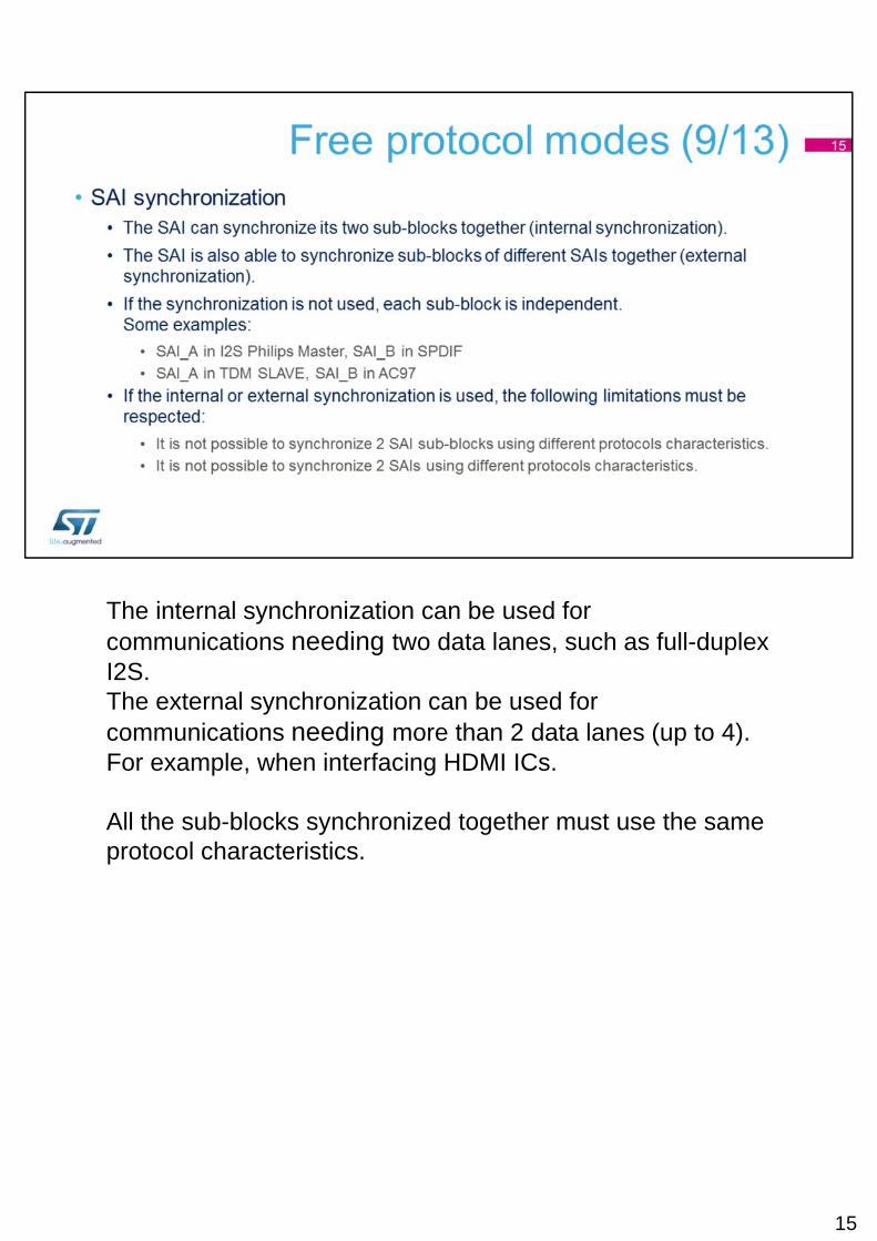
The internal synchronization can be used for communications needing two data lanes, such as full-duplex I2S.The external synchronization can be used for communications needing more than 2 data lanes (up to 4). For example, when interfacing HDMI ICs.
All the sub-blocks synchronized together must use the same protocol characteristics.
15

In order to reduce the data size, it is possible to insert in the data path, an A-law or micro-law compander.Note that A-law and micro-law are not lossless compressors.
Companding modes are generally used in telephony:• The small values are amplified and the big values are
attenuated. • The SNR tends to be identical for a strong and for a
weak signal.
16

The SAI also provides Mute function.In Transmit mode, the user can choose to send zeroes on muted slots or the previous transmitted value. The previous transmitted value is limited to configurations having one or two slots per frame.Note that in Transmit mode, the TxFIFO pointer is still incremented, meaning that data which was present in the FIFO and for which the Mute mode is requested is discarded.
The Receive Mute mode can be helpful to detect an amount of consecutive slots having all data reset to zero.
17

The Anticipated or Late frame error detection function increases the interface’s reliability by detecting unexpected frame synchronization misalignment. A status flag is set and an interrupt can be generated as well. The application software will have to then re-start the SAI interface.
18

The SAI guarantees the data alignment even if an underrunor an overrun occurs.
19

The SAI supports the audio IEC 60958 standard, in Transmit mode when configured for the SPDIF protocol. The SAI generates the preambles and the parity bit (P) according to the transmitted data.The software has to handle the CS, U and V bits.
20
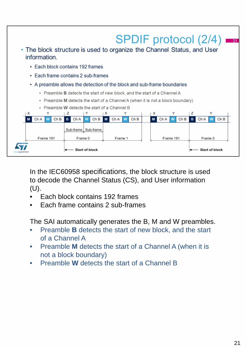
In the IEC60958 specifications, the block structure is used to decode the Channel Status (CS), and User information (U).• Each block contains 192 frames• Each frame contains 2 sub-frames
The SAI automatically generates the B, M and W preambles.• Preamble B detects the start of new block, and the start
of a Channel A• Preamble M detects the start of a Channel A (when it is
not a block boundary)• Preamble W detects the start of a Channel B
21
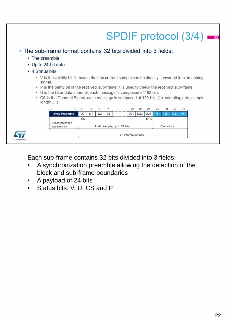
Each sub-frame contains 32 bits divided into 3 fields:• A synchronization preamble allowing the detection of the
block and sub-frame boundaries• A payload of 24 bits• Status bits: V, U, CS and P
22
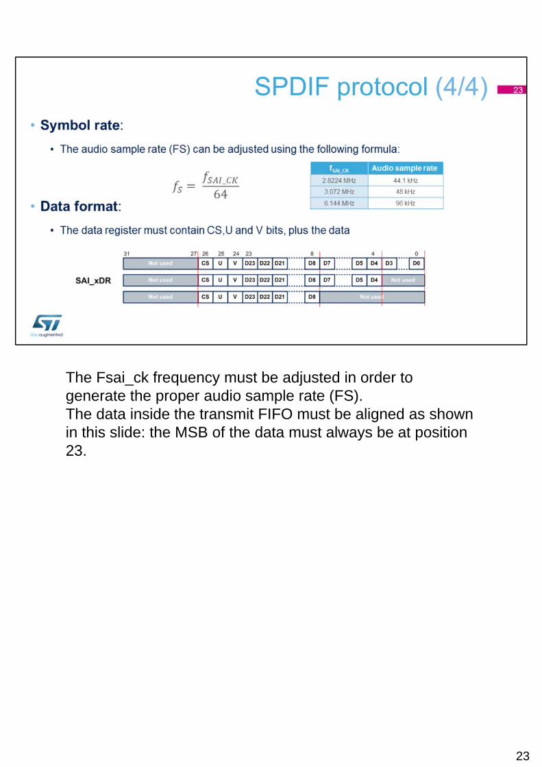
The Fsai_ck frequency must be adjusted in order to generate the proper audio sample rate (FS).The data inside the transmit FIFO must be aligned as shown in this slide: the MSB of the data must always be at position 23.
23

The SAI is able to work as an AC’97 link controller. When this protocol is used, the frame length, the slot number, and slot length are set by the hardware.
24

Several events can be enabled in order to generate interrupts.The WCKCFG event can be used in order to inform the user that the frame length of the SAI has been improperly programmed. This feature only makes sense in Master mode.
25

The following table shows an overview of the SAI activity for the various possible power modes. The SAI is active in Run and Sleep modes, frozen in Stop mode or powered-down in Standby mode. The SAI needs the bus interface clock (APB clock) and the kernel clock (SAI_CK_x) to work properly.

For a full-duplex Master mode, two data lanes are needed, so two sub-blocks need to be used.The master sub-block A provides the synchronization to the slave sub-block B, using the internal synchronization feature (IO Line Management).
Note that in this example, the sub-block B only uses the SD_B. The amount of IOs is reduced to its minimum thanks to the internal synchronization.
27

Another kind of Full-duplex mode, using the TDM protocol.Slot 1 is inactive (not used) for sub-block A, the slots 2 and 3 are inactive for sub-block B.For both sub-blocks, the frame structure has 4 slots.Sub-block A will generate 3 samples per frame.Sub-block B will receive 2 samples per frame.
28