Embed Size (px)
Citation preview

HeLMKe plusthree-phase squirrel cage motors
low voltageFrame size 63-355
dor series
www.helmke.de
english
Ie1 Ie2 Ie3


3
Table of Contents
General specification 4
Standards and regulation .................................................................................................................................................... 4Conditions of installation ..................................................................................................................................................... 4Painting ............................................................................................................................................................................... 5Insulation and temperature rise ........................................................................................................................................... 5Tolerances .......................................................................................................................................................................... 6Mechanical design .............................................................................................................................................................. 7Mounting arrangements ...................................................................................................................................................... 8Lubrication and maintenance of bearings .......................................................................................................................... 10Lubricating nipples ............................................................................................................................................................ 10Electrical design ................................................................................................................................................................ 11Three-phase squirrel-cage motors driven by frequency inverters ..................................................................................... 15
Aluminium Motors 17
Overview aluminium motors .............................................................................................................................................. 17Terminal box ..................................................................................................................................................................... 18Materials ............................................................................................................................................................................ 18Bearings ............................................................................................................................................................................ 18Anti-condensation heating ................................................................................................................................................. 21Noise characteristics ......................................................................................................................................................... 21Position and dimensions of the key ................................................................................................................................... 21Technical data IE2 ............................................................................................................................................................ 22Dimensions IE2 ................................................................................................................................................................. 26Technical data IE3 ............................................................................................................................................................ 28Dimensions IE3 ................................................................................................................................................................. 30
Cast Iron Motors 33
Overview cast iron motors ................................................................................................................................................. 33Terminal box ..................................................................................................................................................................... 34Materials ............................................................................................................................................................................ 34Bearings ............................................................................................................................................................................ 35Anti-condensation heating ................................................................................................................................................. 38Noise characteristics ......................................................................................................................................................... 38Position and dimensions of the key ................................................................................................................................... 39Technical Data IE2 ............................................................................................................................................................ 40Dimensions cast iron motors in frame size 63…180 IE2 ................................................................................................... 48Dimensions cast iron motors in frame size 200...355 IE2 ................................................................................................. 50Technical Data IE3 ............................................................................................................................................................ 54Dimensions cast iron motors in frame size 63…180 IE3 ................................................................................................... 60Dimensions cast iron motors in frame size 200...355 IE3 ................................................................................................. 62
Notes 65
Revisions
All technical data, outputs, dimensions and weights, stated in this catalogue, are subject to change without notice. Illustrations do not purport to show constructional details.

4 General
General specification
Standards and regulation
The motors comply with the relevant standards and regulations, especially:
Electrical
IEC-Standard EN- Standard Content
IEC 60034-1 EN 60034-1 Rating and performance
IEC 60034-8 EN 60034-8 Terminal markings and direction of rotation
IEC 60034-12 EN 60034-12 Starting performance
IEC 60034-30 EN 60034-30 Efficiency classes of single-speed, three-phase, cage-induction motors (IE-code)
IEC 60038 EN 60038 Standard voltages
Mechanical
IEC-Standard EN- Standard Content
IEC 60072 EN 50347 Dimensions and outputs
IEC 60034-5 EN 60034-5 Degrees of protection
IEC 60034-6 EN 60034-6 Methods of cooling
IEC 60034-7 EN 60034-7 Types of construction
IEC 60034-9 EN 60034-9 Noise limits
IEC 60034-14 EN 60034-14 Vibrations
Conditions of installation
The motors are designed for operation at altitudes ≤ 1000 m above sea-level and at coolant temperature of up to 40 C. Exceptions are indicated on the rating plate.
The motors comply with protection degree IP 55 according IEC 60034-5 (higher protection degrees on request).
Motors with standard design for horizontal mounting arrangements are suitable for indoor and protected outdoor installation, climate group MODERATE (temperature of coolant -20° C to +40° C).
In case of unprotected outdoor installation or aggravating climatic conditions (moisture category wet, climate group WORLDWIDE, extremely dusty site conditions, aggressive industrial atmosphere, danger of storm rain and coastal climate, danger of attack by termites, etc.), as well as vertical mounting, special measures are required, such as:
Protective cowl (for vertical mounting with shaft-down)
For vertical mounting with shaft-up flange drainage and additional bearing seal, if necessary
Special painting
Treatment of winding with moisture protection varnish
Anti-condensation heating (anti-condensation heating of winding, if necessary)
Condensation drain holes
The special measures to be applied have to be agreed with us once the conditions of installation have been clarified.
The respective conditions of installation have to be clearly indicated in the order.

General 5
Painting
Standard painting
Suitable for climate group Moderate according to DIN 600 721-2-1, e.g. indoor and outdoor installation
short-term: up to 100 % humidity at temperatures up to +30°C
long-term: up to 85 % humidity at temperatures up to +25°C
Special painting K1
Suitable for climate group Worldwide according to DIN 600 721-2-1, e.g. outdoor installation in aggressive chemical atmos-phere and coastal climate:
short-term: up to 100 % humidity at temperatures up to +35°C
long-term: up to 98 % humidity at temperatures up to +30°C
Special designs (on request)
Special painting K2 (additional treatment of internal motor parts)
Special painting in case of alkalis
Special painting according to customers’ requirements
Insulation and temperature rise
The insulation of the motors complies with temperature class F according EN 60034-1.
The table beside defines the temperature rise (DT*) and maximum temperatures at the hottest points of the winding (Tmax
Class
) according to the temperature classes of the EN 60034-1 standard.
∆T* T
B
max
80 K 125° C
F 105 K 155° C
H 125 K 180° C
In case of coolant temperature of 40° C motors in standard design are only utilized according temperature class B – with an overtemperature limit of 80 K. This also applies for the rated voltage range according IEC 60038. Exceptions are shown on the selection tables.
Derating at coolant temperatures over 40°C
Temperature of coolant 45° C 50° C 55° C 60° C
Reduction of nominal power to approx. 95 % 90 % 85 % 80 %
When a winding is utilized according to temperature class F (105 K), no derating is required up to a coolant temperature of 60 °C.
This does not apply to motors which are already utilized according to thermal class F in their standard de-sign.
Installation at altitudes of more than 1000 m above sea level (also see EN 60034-1)
In case of higher altitudes and coolant temperature of 40°C the nominal power has to be reduced approximately to the values defined in the table beside.
Temperature class
Altitude
2000 m 3000 m 4000 m
B 89 % 79 % 68 %
F 92 % 84 % 76 %

6 General
Installation at altitudes of more than 1000 m above sea level (also see EN 60034-1)
If the full nominal power according to the selection table is necessary, the temperature of the coolant is to be decreased according to the table be-side.
Temperature class
Altitude
2000 m 3000 m 4000 m
B 30° C 19° C 9° C
F 32° C 24° C 16° C
Tolerances
For industrial motors according to EN 60034-1, certain tolerances must be allowed on guaranteed values, taking into con-sideration the tolerances for the manufacture of such motors and the variances of the used materials. The standard specifi-cation sheet includes the following remarks:
Guarantee of all or any of the values according to the table is not obligatory. Guaranteed values that are subject to tol-erance have to be mentioned in offers explicit. The allowed tolerances must be in accordance with the table.
Where a tolerance is stated in only one direction, the value is not limited in the other direction.
Values for Tolerance
Efficiency (η) (in case of indirect determination)
-0,15 x (1 − η) at PN ≤ 50 kW -0,1 x (1 − η) at PN
Power factor (cos ϕ)
> 50 kW
6cos 1 ϕ−
− , minimum 0.02, maximum 0.07
Slip (s) (at rated load and at working tempera-ture)
±20 % of the guaranteed slip at PN ≥ 1 kW ±30 % of the guaranteed slip at PN
Starting current (I
< 1 kW
S +20 % of the guaranteed starting current no lower limit
) (in case of the intended starting circuit)
Starting torque (TS -15 % and +25 % of the guaranteed starting torque (+25 % may be exceeded by agreement)
)
Pull-up torque (TP -15 % of the guaranteed value )
Breakdown torque (TB -10 % of the guaranteed value (after allowing for this tolerance, T
) B /TN
Moment of inertia (I)
at least 1,6)
±10 % of the guaranteed value
Mechanical tolerances
According to IEC 72-1, the tolerances on me-chanical dimensions of electric motors given beside are permitted.
Note: The holes at the shaft end correspond with DIN 332
Parameter Code Area Tolerance
Frame size H up to 250 > 250
0.5 mm 1 mm
Diameter of shaft end D-DA from 11 to 28 mm from 38 to 48 mm from 55 to 100 mm
j6 k6 m6
Hub key width F-FA h9
Flange centring N up to 132 > 132
j6 h6

General 7
Mechanical design
Protection degrees
Protection degrees for electrical machines are designated in accordance with IEC 60034-5 by the letters IP and two charac-teristic numerals.
First numeral: Protection against contact and ingress of foreign bodies
Second numeral: Protection against ingress of water
IP Description
0 No special protection
1 Protection against solid foreign bodies larger than 50 mm (Example: inadvertent contact with the hand)
2 Protection against solid foreign bodies larger than 12 mm (Example: inadvertent contact with the fingers)
3 Protection against solid foreign bodies larger than 2.5 mm (Example: Wires, tools)
4 Protection against solid foreign bodies larger than 1 mm (Example: Wires, bands)
5 Protection against dust (harmful deposits of dust)
6 Total protection against dust (is not described for electrical machines according IEC 34-5)
IP Description
0 No special protection
1 Protection against vertically falling water drops (condensation)
2 Protection against dropping water when inclined by up to 15°
3 Protection against spray water up to 60° from verti-cal
4 Protection against shower water from any direction
5 Protection against water projected by a nozzle and from any direction
6 Protection against heavy seas or water projected in powerful jets
7 Protection when submerged between 0,15 and 1 m
8 Protection when continuously submerged in water at conditions agreed between the manufacturer and the user

8 General
Mounting arrangements
Mounting arrangements for rotating electrical machines are designated according to IEC 60034-7, Code I (in brackets Code II).
Our motors are available according to the table depending on design and frame size. Motors with aluminium frame are equipped with removable feet that allow easy change of mounting arrangement.
Foot mounting Flange mounting Motors without end shield
IM B3 (IM 1001) IM B5 (IM 3001) IM B9 (IM 9101)
Mounting flange type A according DIN 42 948 at drive end
Without end shield and with-out roller bearing on drive end
IM B6 (IM 1051) * IM V1 (IM 3011) IM V8 (IM 9111)
Mounting flange type A according DIN 42 948 at drive end
Without end shield and with-out roller bearing on drive end
IM B7 (IM 1061) * IM V3 (IM 3031) IM V9 (IM 9131)
Mounting flange type A according DIN 42 948 at drive end
Without end shield and with-out roller bearing on drive end
IM B8 (IM 1071) * IM B35 (IM 2001) IM B15 (IM 1201)
Mounting flange type A according DIN 42 948 at drive end
Without end shield and with-out roller bearing on drive end
IM V5 (IM 1011) * IM B14 (IM 3601)
Mounting flange type C according DIN 42 948 at drive end
IM V6 (IM 1031) * IM V18 (IM 3611)
Mounting flange type C according DIN 42 948 at drive end
IM B34 (IM 2101) IM V19 (IM 3631)
Mounting flange type C according DIN 42 948 at drive end
Mounting flange type C according DIN 42 948 at drive end
* From frame size 225 on request
It is essential to state the desired mounting arrangement when ordering, as the constructive design depends partly on the mounting arrangement.

General 9
Terminal boxes
The location of the terminal box in standard design is on top (view to drive end); on the right or on the left is also possible. For motors with mounting arrangements IM B6, IM B7, IM B8, IM V5, IM V6 the location of the terminal box is related to an IM B3 mounting.
The position of the entry openings can be adapted to the existing connection possibilities for most motors by turning the terminal box by 90°. Please enquire if special accessories should be used (temperature sensors, anti-condensation heating, etc.).
For motors in standard design, the screwed stuffing boxes do not belong to our scope of delivery.
Belt drive
The data refer only to the normal shaft end at the drive end of IM B3 motors with one speed.
Calculation of radial shaft load: N][
nDkP19120F
1R ⋅
⋅⋅= FR
P = power in kW = radial shaft load in N
n = speed in minD
-1 1
k = belt tension factor = pulley diameter in m
The belt tension factor depends on the type of belt and is assumed to be approximately:
3...4 for normal flat belt without idle pulley 2...2,5 for normal flat belt with idle pulley 2,2...2,5 for V-belt
Please enquire exact data from the belt manufacturer.
Vibration behaviour
The vibration severity of electric motors is determined in EN 60034-14 Mechanical vibration of certain machines with shaft heights 56 and higher - Measurement, evaluation and limits of vibration severity.
The rotors of the motors are dynamically balanced with half key fitted according to DIN ISO 8821. Other balancing is avail-able by agreement only.
Our standard motors observe or fall below vibration category A. Motors with ball bearing can be supplied in vibration cate-gory B at extra cost.
10 General
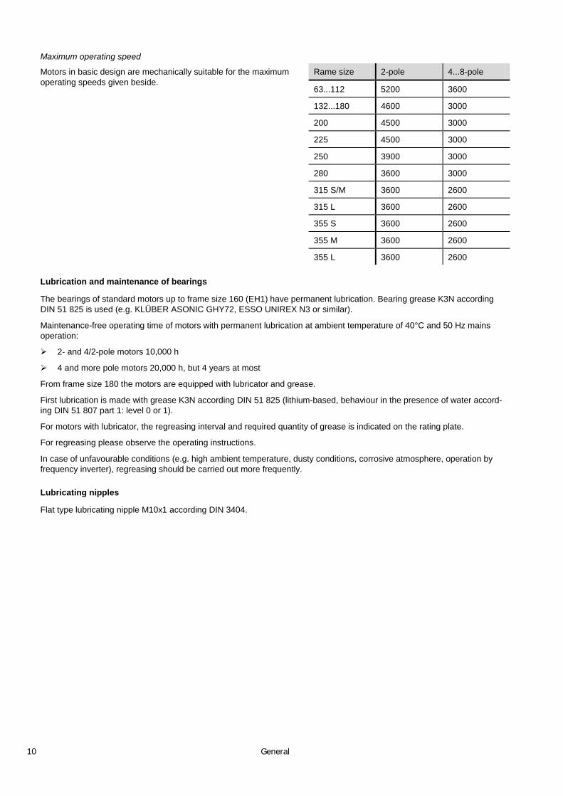
Maximum operating speed
Motors in basic design are mechanically suitable for the maximum operating speeds given beside.
Rame size 2-pole 4...8-pole
63...112 5200 3600
132...180 4600 3000
200 4500 3000
225 4500 3000
250 3900 3000
280 3600 3000
315 S/M 3600 2600
315 L 3600 2600
355 S 3600 2600
355 M 3600 2600
355 L 3600 2600
Lubrication and maintenance of bearings
The bearings of standard motors up to frame size 160 (EH1) have permanent lubrication. Bearing grease K3N according DIN 51 825 is used (e.g. KLÜBER ASONIC GHY72, ESSO UNIREX N3 or similar).
Maintenance-free operating time of motors with permanent lubrication at ambient temperature of 40°C and 50 Hz mains operation:
2- and 4/2-pole motors 10,000 h
4 and more pole motors 20,000 h, but 4 years at most
From frame size 180 the motors are equipped with lubricator and grease.
First lubrication is made with grease K3N according DIN 51 825 (lithium-based, behaviour in the presence of water accord-ing DIN 51 807 part 1: level 0 or 1).
For motors with lubricator, the regreasing interval and required quantity of grease is indicated on the rating plate.
For regreasing please observe the operating instructions.
In case of unfavourable conditions (e.g. high ambient temperature, dusty conditions, corrosive atmosphere, operation by frequency inverter), regreasing should be carried out more frequently.
Lubricating nipples
Flat type lubricating nipple M10x1 according DIN 3404.

General 11
Electrical design
Rated voltage
For the rated voltage of the motors a voltage tolerance of ±10 % applies. According to IEC 60038 the mains voltages may have a tolerance of ±10 %.
When the motors are operated at the limits of the voltage tolerance, the permissible overtemperature of the stator winding may be exceeded by 10 K.
Rated frequency
Motors with windings for 50 Hz can be also operated on 60 Hz mains, when the mains voltage increases proportionally to the frequency. The relative values for starting and breakaway torque remain nearly unchanged and slightly increase for the starting current. The rated speed increases by the factor 1,2 and the rated power by factor 1,15. Should a motor designed for 50 Hz be operated at 60 Hz without the voltage being increased, the rated power of the motor cannot be increased. Un-der these operating conditions, the rated speed increases by factor 1,2. The relative values for starting and breakaway torque are reduced by factor 0,82 and the starting current by factor 0,9.
Rated current
The rated currents listed in the selection tables apply to an operating voltage of 400 V. The conversion to other operating voltages, with power and frequency remaining unchanged, is to be made as follows:
Rated voltage (V) 230 380 400 440 500 660 690
Conversion factor x l 1,74 N 1,05 1,0 0,91 0,80 0,61 0,58
Rated torque
rpmin speed RatedkWin power Shaft 9550 Nmin torqueRated ⋅=
Power
The power stated in the table applies for constant load at continuous operation according duty class S1 of EN 60034-1, based on a coolant temperature of 40°C and installation at altitudes up to 1000 m above sea level.
For severe operating conditions, e.g. high switching rate, long run-up time or electric braking, a thermal reserve is neces-sary, which may require a higher temperature class or the use of a motor with higher rating. In these cases we recommend further enquiring and specification of the operating conditions.
Overload capability
At operating temperature three-phase motors are capable of withstanding an overload for 2 minutes ( ≤ frame size 112: 15 seconds) with 1,5 times of the rated current at rated voltage. This overload capability complies with EN 60034-1 and will not result in excessive temperature rise.
When temperature class F is utilized, motors can be operated continuously with an overload of 12 %. This does not apply to motors which are already utilized according to thermal class F in their standard design.

12 General
Connection diagrams
Star connection
Star connection is obtained by connecting terminals W2, U2, V2 to each other and terminals U1, V1, W1 to the mains.
Phase current and phase voltage are: Iph = IN; Vph = VN 3 /
IN is the rated current and VN
the rated voltage at star connection.
Delta connection
Delta connection is obtained by connecting the end of a phase to the begin-ning of the next phase.
Phase current and phase voltage are: Iph = IN 3 / ; Vph = V
I
N
N and VN
are rated current and rated voltage at delta connection.
Star-delta connexion
Star-delta connection permits a reduction of the starting current, ensuring however that the resulting starting torque obtained is higher than the load torque. Thereby it should be observed that the torque of an asynchronous motor is directly propor-tional to the square of the voltage. Motors whose rated voltage with delta connection corresponds to the mains voltage, can be started with the star-delta method.
All motors can be supplied with windings designed for star-delta starting (for example: 400 V Δ / 690 V Y).
Starting rate
The number of starts per hour given in the table below is permitted without specific check, provided that the following conditions are met:
Additional moment of inertia ≤ moment of inertia of the rotor
Load torque increases to nominal torque quadratic to the speed
Starting in evenly intervals
Zulässige Anläufe / Stunde bei Polzahl
Baugröße 2 4 ≥ 6
56...71 100 250 350
80...100 60 140 160
112...132 30 60 80
160...180 15 30 50
200...225 8 15 30
250...315 4 8 12
Please consult us and specify the complete operating conditions in order to ask for the permissible number of starts for mo-tors of frame size 355.

General 13
Motor protection
The selection of the thermal motor protection should result from the existing operating conditions. Motors may be protected by means of current-dependent motor circuit breakers or overcurrent relays and temperature sensors.
Motor protection is possible as follows:
Motor circuit breaker with bimetal switch
Thermistor protection with thermistor temperature sensors (PTC) in the stator winding combined with relay (if required, with additional motor circuit breaker).
Bimetal temperature sensor as N.C. or N.O. in the stator winding (if required, with additional motor circuit breaker).
Resistance thermometer for monitoring of winding and bearing temperature.
If motor protection is necessary, motor circuit breakers with bimetal switches or thermistor temperature sensors (PTC) can be built in.
Although there are motors available from stock with built-in thermistor temperature sensor, a special remark has to be made in the enquiry or order when motor protection is required.
Functionality of bimetal temperature sensors
Ti Activation temperature
Tr Reset temperature
Functionality of thermistor temperature sensors (type PTC)
Ti Activation temperature
Type N/C (normally open) Type N/C (normally closed)

14 General
Connection examples
Protective measure Protection against...
Motor circuit breaker with thermal and electro-magnetic overcurrent release
Overload at continuous operation
Blocked rotor
Contactor with overcurrent relay
Thermistor protection and fuse
during operation against :
Overload at continuous operation
Long starting and braking periods
High switching rate
in case of fault against:
Obstruction of cooling
Increased temperature of coolant
Single-phase operation
Frequency variations
Blocked rotor
Thermistor temperature sensor with release
during operation against :
Overload at continuous operation
Long starting and braking periods
High switching rate
in case of fault against :
Obstruction of cooling
Increased temperature of coolant
Single-phase operation
Frequency variations
Blocked rotor

General 15
Three-phase squirrel-cage motors driven by frequency inverters
The motors in standard design are suitable for operation on static frequency inverters, taking into account the following re-marks:
Maximum inverter output voltage 500 V at peak voltages Û ≤ 1460 V and dv/dt ≤ 13 kV/ms. For higher inverter output voltages or higher stress a special insulation is required.
At square characteristic of the load torque, motors can be operated with their rated torque (exceptions are marked in the selection tables).
In case of constant torque, the rated torque must be reduced for self-ventilated motors due to reduced supply of cooling air. Depending on the speed range, the use of an external fan is recommendable.
Standard motors designed for 230V ∆ / 400V Y, 50 Hz can be operated with delta connection at 400 V and a base fre-quency of 87 Hz (observe the mechanical speed limits).
For motors from frame size 280 we recommend an insulated bearing at the non-drive end.
T/T
0
0,1
0,2
0,3
0,4
0,5
0,6
0,7
0,8
0,9
1
1,1
1,2
0 10 20 30 40 50 60 70 80 90
1
2
3N
f1
Forced ventilation [Hz]
Self-ventilation, motors 2p = 2
Self-ventilation, motors 2p = 4..8
Voltage capability
The insulating system of the motors is suitable for inverter output voltages ≤ 500 V. Higher voltages are available on request.
Noises
Depending on the operating point, the type of inverter and the set pulse frequency, inverter-fed motors produce between 1 and 15 dB(A) higher noise values than at mains operation.
Motors that are operated with a frequency over 50 Hz have more air noise. In this case we recommend the use of an exter-nal fan.
Vibration severity
When operating at high speeds (according to frequency > 60 Hz) a reduced vibration severity “B” according to EN 60034 part 14 may be required, measured at a mains frequency of 50 Hz or 60 Hz and sinusoidal mains voltage.


Aluminium Motors 17
Aluminium Motors
These asynchronous three-phase motors in a light metal design with a low motor weight and simple to adjustable terminal box position are available in various designs.
This motor range is deliverable ex stock for the whole power range
Overview aluminium motors
Type Frame size Rated power [kW]
2-pole 4-pole 6-pole 8-pole
DOR63M1 63 0,18 0,12 − −
DOR63M2 63 0,25 0,18 − −
DOR71M1 71 0,37 0,25 0,18 −
DOR71M2 71 0,55 0,37 0,25 −
DOR80M1 80 0,75 0,55 0,37 0,18
DOR80M2 80 1,1 0,75 0,55 0,25
DOR90S 90S 1,5 1,1 0,75 0,37
DOR90L 90L 2,2 1,5 1,1 0,55
DOR100L, L1 100L 3,0 2,2 1,5 0,75
DOR100L2 100L − 3,0 − 1,1
DOR112M 112M 4,0 4,0 2,2 1,5
DOR132S1 132S 5,5 − − −
DOR132S, S2 132S 7,5 5,5 3,0 2,2
DOR132M1 132M − − 4,0 −
DOR132M, M2 132M − 7,5 5,5 3,0
DOR160M1 160M 11 − − 4,0
DOR160M, M2 160M 15 11 7,5 5,5
DOR160L 160L 18,5 15 11 7,5
General data
Voltage/Connection up to 2,2 kW: 230 V ∆ / 400 V Y from 3,0 kW: 400 V ∆ / 690 V Y
Mounting arrangements IM 1001 (B3), IM 3001 (B5), IM 3601 (B14) feet can be mounted on flange-mounted motors
Thermistor 3 PTC built-in standard-like

18 Aluminium Motors
Terminal box
Frame size Degree of protection
Hole for ca-ble entry
Metric
Connection for temperature sensor
Metric
Max. conductor cross section
[mm2
Connecting bolt
]
Max. external cable diameter
[mm]
63 IP 55 1 x M20x1,5 1 x M20x1,5 2,5 M4 13
71 IP 55 1 x M20x1,5 1 x M20x1,5 2,5 M4 13
80 IP 55 1 x M20x1,5 1 x M20x1,5 2,5 M4 13
90 IP 55 1 x M20x1,5 1 x M20x1,5 2,5 M4 13
100 IP 55 1 x M20x1,5 1 x M20x1,5 2,5 M4 13
112 IP 55 2 x M32x1,5 1 x M20x1,5 4 M4 21
132 IP 55 2 x M32x1,5 1 x M20x1,5 4 M4 21
160 IP 55 2 x M40x1,5 1 x M25x1,5 16 M5 27
Materials
Designation Frame size Material
Stator frame 63…160 Aluminium alloy
End shield 63…160 Aluminium alloy from frame size 90 with steel bush at drive end (seat of the bearing)
Flanged endshield 63…160 Aluminium alloy from frame size 90 with steel bush at drive end (seat of the bearing)
Fan cover 63…160 Sheet steel
Fan 63…160 Plastic material
Terminal box 63…160 Aluminium alloy
Bearings
Allocation of bearings (standard design)
Ball bearings according to ISO 15 (DIN 625)
Frame size No. of poles Drive end Non-drive end
63 2...8 6201-2Z C3 6201-2Z C3
71 2...8 6202-2Z C3 6202-2Z C3
80 2...8 6204-2Z C3 6204-2Z C3
90 2...8 6205-2Z C3 6205-2Z C3
100 2...8 6206-2Z C3 6206-2Z C3
112 2...8 6306-2Z C3 6306-2Z C3
132 2...8 6308-2Z C3 6308-2Z C3
160 2...8 6309-2Z C3 6309-2RS C3 (IE2) 6209-2RS C3 (IE3)

Aluminium Motors 19
Standard design of bearings
(other designs on request) Frame size Bearing drive end
Bearing non-drive end
Spring-loaded
63...160 Located bearing
Non-located bearing
Non-drive end
Maximum permissible axial loads without additional radial load
Values are valid for 50 Hz. For 60 Hz operation the values have to be reduced by 10%. (if additional radial forces affect, enquiry is necessary depending on the direction of force)
Horizontal shaft
Frame size Axial load [kN]
3000 min 1500 min-1 1000 min-1 750 min-1
63
-1
0,25 0,28 − −
71 0,27 0,35 0,44 −
80 0,38 0,47 0,59 0,62
90 0,44 0,55 0,62 0,64
100 0,61 0,75 0,88 0,89
112 1,22 1,44 1,65 1,78
132 1,50 1,78 1,82 1,92
160 1,65 2,10 2,45 2,65
Vertical shaft downwards
Frame size Axial load upwards [kN] Axial load downwards [kN]
3000 min 1500 min-1 1000 min-1 750 min-1 3000 min-1 1500 min-1 1000 min-1 750 min-1
63
-1
0,26 0,3 − − 0,23 0,26 − −
71 0,29 0,37 0,46 − 0,25 0,32 0,42 −
80 0,40 0,49 0,62 0,65 0,36 0,45 0,56 0,59
90 0,47 0,60 0,68 0,70 0,41 0,51 0,46 0,58
100 0,67 0,84 0,97 0,97 0,57 0,71 0,82 0,84
112 1,30 1,52 1,74 1,88 1,17 1,37 1,58 1,71
132 1,62 1,97 2,00 2,10 1,43 1,61 1,66 1,76
160 1,95 2,47 2,80 3,05 1,35 1,72 2,05 2,21

20 Aluminium Motors
Permissible radial loads
without additional axial load (ball bearing)
max. permissible radial loads in the table are valid for X = 1/2 shaft length
Frame size FR
2
in N for number of poles
4 6 8
63 300 300 − −
71 400 400 400 −
80 610 650 750 820
90S/L 660 710 810 890
100L 920 990 1130 1240
112M 1330 1430 1640 1800
Nominal life cycle = 20,000 h (Lh 10)
FR
X = Distance between working point of force and shaft shoulder (e.g. half pulley width)
= permissible radial load in kN (without additional axial load)
A modification of the normal design to cylindrical roller bearings is not possible.
For calculation of the radial forces see Belt drive on page 9.

Aluminium Motors 21
Anti-condensation heating
Motors which are exposed to a risk of humidity during standstill due to severe temperature variations can be equipped with anti-condensation heating (strip heaters) for an extra charge, if requested.
The supply voltage and the heating power of the strip heat-ers can be taken from the table beside.
Frame size Supply voltage [V] Heizleistung/Motor [W]
132…160 230 2x40
During operation of the motor, the anti-condensation heating must be switched off.
Noise characteristics
The noise values listed beside are valid for 50 Hz at rated voltage with a tolerance of up to +3 dB(A).
3...5 dB(A) higher values are the recommended values for operation at 60 Hz.
Frame size Sound pressure level Lpa
2-pole
[dB(A)]
4-pole 6-pole 8-pole
71 53 44 40 37
80 56 47 41 40
90 60 49 45 41
100 64 53 49 44
112 65 54 53 48
132 68 62 63 50
160 74 66 66 54
Position and dimensions of the key
Frame size Dimensions [mm]
D X E F X GD ED EE GA
71 14 X 30 5 X 5 25 2,5 16
80 19 X 40 6 X 6 30 5 21,5
90 24 X 50 8 X 7 40 5 27
100 28 X 60 8 X 7 50 5 31
112 28 X 60 8 X 7 50 5 31
132 38 X 80 10 X 8 65 7,5 41
160 42 X 110 12 X 8 90 10 45
For longer shafts in special design the dimensions ED and EE are kept.

22 Aluminium Motors
Technical data IE2
Ratings for mains operation For direct-on-line starting
Type Frame size
Rated power
Rated speed
Rated torque
Efficiency class acc. to EN 60034-30
Efficiency EN60034-2-1 : 2007
Power factor
Rated current at
IN
Start-ing current
[A]
Start-ing torque
Break-down torque
P nN TN N η [%] cos ϕ 380... 420V
IS/I TN S/T TN B/T
N
[kW] [min-1 [Nm] ] 100% 75% 50% 400V
Helmke DOR – aluminium Motors IE2
3000 min-1 (2-pole)
DOR63M1-02-1A 63 0,18 2710 0,63 63,0 62,8 59,2 0,75 0,54 0,57 6,0 2,2 2,4
DOR63M2-02-1A 63 0,25 2710 0,88 65,0 64,8 61,2 0,78 0,71 0,74 6,0 2,2 2,4
DOR71M1-02-1A 71 0,37 2730 1,29 70,0 69,8 66,5 0,79 0,96 1,01 6,0 2,2 2,4
DOR71M2-02-1A 71 0,55 2740 1,91 71,0 70,8 67,6 0,79 1,41 1,48 6,0 2,2 2,4
DOR80M1-02-2A 80 0,75 2875 2,49 IE2 77,4 77,2 74,5 0,83 1,68 1,76 5,8 2,9 3,3
DOR80M2-02-2A 80 1,1 2870 3,66 IE2 79,6 79,4 76,9 0,83 2,4 2,52 6,8 3,5 3,6
DOR90S-02-2A 90 1,5 2885 4,9 IE2 81,3 81,1 78,7 0,84 3,17 3,32 6,9 3,5 3,6
DOR90L-02-2A 90 2,2 2875 7,3 IE2 83,2 83,1 80,8 0,85 4,4 4,7 7,9 4,1 4,1
DOR100L-02-2A 100 3 2880 9,9 IE2 84,6 84,5 82,4 0,87 5,8 6,1 7,8 3,4 3,4
DOR112M-02-2A 112 4 2900 13,1 IE2 85,8 85,7 83,7 0,88 7,6 8,0 7,5 2,7 3,3
DOR132S1-02-2A 132 5,5 2920 17,9 IE2 87,0 86,9 85,1 0,86 10,6 11,1 7,7 2,4 3,0
DOR132S2-02-2A 132 7,5 2915 24,5 IE2 88,1 88,0 86,3 0,88 13,9 14,6 8,4 2,6 3,2
DOR160M1-02-2A 160 11 2930 35,8 IE2 89,4 89,3 87,8 0,89 19,9 20,9 7,6 2,4 3,1
DOR160M2-02-2A 160 15 2930 48,8 IE2 90,3 90,2 88,8 0,89 26,9 28,2 8,0 2,6 3,2
DOR160L-02-2A 160 18,5 2935 60,1 IE2 90,9 90,8 89,5 0,89 33 34,6 9,0 3,0 3,5
1500 min-1 (4- pole)
DOR63M1-04-1A 63 0,12 1330 0,86 57,0 56,8 53,0 0,64 0,47 0,49 4,0 2,2 2,4
DOR63M2-04-1A 63 0,18 1330 1,29 59,0 58,8 55,1 0,65 0,67 0,71 6,0 2,2 2,4
DOR71M1-04-1A 71 0,25 1330 1,79 60,0 59,8 56,1 0,72 0,83 0,87 6,0 2,2 2,4
DOR71M2-04-1A 71 0,37 1330 2,65 65,0 64,8 61,2 0,74 1,11 1,16 6,0 2,2 2,4
DOR80M1-04-1A 80 0,55 1370 3,83 67,0 66,8 63,3 0,75 1,57 1,65 6,0 2,2 2,4
DOR80M2-04-2A 80 0,75 1400 5,1 IE2 79,6 79,4 76,9 0,75 1,81 1,9 5,3 2,8 3,0
DOR90S-04-2A 90 1,1 1440 7,2 IE2 81,4 81,2 78,8 0,77 2,53 2,65 6,7 3,8 2,6
DOR90L-04-2A 90 1,5 1440 9,9 IE2 82,8 82,7 80,4 0,77 3,39 3,56 7,2 4,0 2,7
DOR100L1-04-2A 100 2,2 1440 14,5 IE2 84,3 84,2 82,0 0,81 4,6 4,8 7,4 3,6 3,6
DOR100L2-04-2A 100 3 1440 19,8 IE2 85,5 85,4 83,4 0,82 6,1 6,4 7,8 3,8 3,5
DOR112M-04-2A 112 4 1445 26,4 IE2 86,6 86,5 84,6 0,82 8,1 8,5 7,1 3,1 2,9
DOR132S-04-2A 132 5,5 1455 36 IE2 87,7 87,6 85,9 0,83 10,9 11,4 7,4 2,6 2,7
DOR132M-04-2A 132 7,5 1455 49,2 IE2 88,7 88,6 87,0 0,84 14,5 15,2 7,7 2,8 2,7
DOR160M-04-2A 160 11 1460 71,9 IE2 89,8 89,7 88,2 0,84 21,0 22,1 7,7 2,7 3,1
DOR160L-04-2A 160 15 1460 98,1 IE2 90,6 90,5 89,1 0,85 28,1 29,5 7,3 2,4 2,6

Aluminium Motors 23
Ratings for operation with IGBT converter
Type T ∼ n2
Speed range 5...50 Hz
, self-ventilated or T = constant, forced-ventilated
T = constant, self-ventilated Speed range 17...50 Hz
T = constant, self-ventilated Speed range 5...50 Hz
Inertia Weight
P at 50 Hz I Temp. class
P at 50 Hz T I P at 50 Hz T I J
[10-3 kgm2
] [kW] [A] [kW] [Nm] [A] [kW] [Nm] [A] [kg]
Helmke DOR – aluminium motors IE2
3000 min-1 (2-pole)
DOR63M1-02-1A 0,18 0,57 F 0,15 0,52 0,48 0,12 0,42 0,41 0,14 4
DOR63M2-02-1A 0,25 0,74 F 0,21 0,74 0,62 0,18 0,63 0,53 0,16 4,2
DOR71M1-02-1A 0,37 1,01 F 0,31 1,08 0,85 0,26 0,9 0,72 0,34 5,2
DOR71M2-02-1A 0,55 1,48 F 0,46 1,6 1,25 0,39 1,35 1,06 0,42 6
DOR80M1-02-2A 0,75 1,76 F 0,63 2,09 1,49 0,54 1,79 1,26 0,78 8,7
DOR80M2-02-2A 1,1 2,52 F 0,93 3,09 2,14 0,79 2,62 1,81 0,98 10
DOR90S-02-2A 1,5 3,32 F 1,27 4,2 2,82 1,08 3,57 2,39 1,5 13
DOR90L-02-2A 2,2 4,7 F 1,87 6,2 3,99 1,58 5,2 3,38 1,6 15
DOR100L-02-2A 3 6,1 F 2,55 8,4 5,1 2,16 7,1 4,3 3,2 24
DOR112M-02-2A 4 8 F 3,4 11,1 6,8 2,88 9,4 5,7 4,9 25
DOR132S1-02-2A 5,5 11,1 F 4,6 15,0 9,4 3,96 12,9 7,9 11,6 43
DOR132S2-02-2A 7,5 14,6 F 6,3 20,6 12,4 5,4 17,6 10,5 14,3 48
DOR160M1-02-2A 11 20,9 F 9,3 30,3 17,7 7,9 25,7 15,0 47 77
DOR160M2-02-2A 15 28,2 F 12,7 41,3 23,9 10,8 35,2 20,3 57,2 92
DOR160L-02-2A 18,5 34,6 F 15,7 51,0 29,4 13,3 43,2 24,9 66 104
1500 min-1
DOR63M1-04-1A
(4- pole)
0,12 0,49 F 0,09 0,64 0,37 0,07 0,5 0,3 0,28 3,7
DOR63M2-04-1A 0,18 0,71 F 0,13 0,93 0,53 0,11 0,78 0,44 0,32 4,2
DOR71M1-04-1A 0,25 0,87 F 0,19 1,36 0,66 0,15 1,07 0,54 0,51 5
DOR71M2-04-1A 0,37 1,16 F 0,28 2,01 0,88 0,23 1,65 0,72 8,1 5,8
DOR80M1-04-1A 0,55 1,65 F 0,41 2,85 1,25 0,34 2,37 1,03 1,2 8,1
DOR80M2-04-2A 0,75 1,9 F 0,57 3,88 1,44 0,46 3,13 1,18 1,9 10
DOR90S-04-2A 1,1 2,65 F 0,83 5,5 2,01 0,68 4,5 1,65 2,4 14
DOR90L-04-2A 1,5 3,56 F 1,14 7,5 2,7 0,93 6,1 2,22 3,1 17
DOR100L1-04-2A 2,2 4,8 F 1,67 11,0 3,64 1,37 9,0 3,0 6 20
DOR100L2-04-2A 3 6,4 F 2,28 15,1 4,8 1,87 12,4 4,0 7,3 21
DOR112M-04-2A 4 8,5 F 3,04 20 6,4 2,5 16,5 5,3 11,1 30
DOR132S-04-2A 5,5 11,4 F 4,1 26,9 8,6 3,43 22,5 7,1 23,6 43
DOR132M-04-2A 7,5 15,2 F 5,7 37,4 11,5 4,6 30,1 9,5 29,9 52
DOR160M-04-2A 11 22,1 F 8,3 54,2 16,7 6,8 44,4 13,8 84,5 83
DOR160L-04-2A 15 29,5 F 11,4 74,5 22,4 9,3 60,8 18,4 110 102

24 Aluminium Motors
Ratings for mains operation For direct-on-line starting
Type Frame size
Rated power
Rated speed
Rated torque
Efficiency class acc. to EN 60034-30
Efficiency EN60034-2-1 : 2007
Power factor
Rated current at
IN
Start-ing current
[A]
Start-ing torque
Break-down torque
P nN TN N η [%] cos ϕ 380... 420V
IS/I TN S/T TN B/T
N
[kW] [min-1 [Nm] ] 100% 75% 50% 400V
Helmke DOR – aluminium Motors IE2
1000 min-1
DOR71M1-06-1A
(6-pole)
71 0,18 850 2,02 56,0 55,8 52,0 0,66 0,7 0,73 4,0 1,6 1,7
DOR71M2-06-1A 71 0,25 850 2,8 59,0 58,8 55,1 0,68 0,89 0,94 4,0 2,1 2,2
DOR80M1-06-1A 80 0,37 885 3,99 62,0 61,8 58,1 0,70 1,23 1,29 4,0 1,9 1,9
DOR80M2-06-1A 80 0,55 885 5,9 65,0 64,8 61,2 0,72 1,69 1,78 4,0 2,0 2,3
DOR90S-06-2A 90 0,75 935 7,6 IE2 75,9 75,7 72,8 0,72 1,98 2,07 4,7 3,1 3,1
DOR90L-06-2A 90 1,1 945 11,1 IE2 78,1 77,9 75,2 0,72 2,82 2,96 5,0 3,2 3,2
DOR100L-06-2A 100 1,5 945 15,1 IE2 79,8 79,6 77,1 0,75 3,61 3,79 5,9 3,1 2,9
DOR112M-06-2A 112 2,2 960 21,8 IE2 81,8 81,7 79,3 0,76 5,1 5,3 5,5 2,6 2,8
DOR132S-06-2A 132 3 965 29,6 IE2 83,3 83,2 80,9 0,76 6,8 7,1 5,7 2,2 2,7
DOR132M1-06-2A 132 4 965 39,5 IE2 84,6 84,5 82,4 0,76 8,9 9,4 6,2 2,4 2,7
DOR132M2-06-2A 132 5,5 965 54,4 IE2 86,0 85,9 83,9 0,77 11,9 12,5 6,7 2,6 2,7
DOR160M-06-2A 160 7,5 970 73,8 IE2 87,2 87,1 85,3 0,78 15,9 16,7 5,6 2,0 2,8
DOR160L-06-2A 160 11 970 108 IE2 88,7 88,6 87,0 0,78 22,9 24,0 5,8 2,0 2,8
750 min-1
DOR80M1-08-1A
(8- pole)
80 0,18 645 2,66 50,3 50,0 46,2 0,61 0,84 0,88 2,8 1,5 1,7
DOR80M2-08-1A 80 0,25 645 3,7 54,0 53,8 50,0 0,61 1,09 1,15 2,7 1,6 2,0
DOR90S-08-1A 90 0,37 670 5,2 62,0 61,8 58,1 0,61 1,41 1,48 2,8 1,6 1,8
DOR90L-08-1A 90 0,55 670 7,8 63,0 62,7 59,1 0,61 2,06 2,17 3,0 1,6 1,8
DOR100L1-08-1A 100 0,75 680 10,5 66,0 65,8 62,3 0,67 2,44 2,57 3,5 1,7 2,1
DOR100L2-08-1A 100 1,1 680 15,4 72,0 71,8 68,6 0,69 3,19 3,35 3,5 1,7 2,1
DOR112M-08-1A 112 1,5 690 20,7 74,0 73,8 70,8 0,68 4,3 4,5 4,2 1,8 2,1
DOR132S-08-1A 132 2,2 705 29,8 75,0 74,8 71,9 0,71 5,9 6,2 5,5 2,0 2,0
DOR132M-08-1A 132 3 705 40,6 77,0 76,8 74,0 0,73 7,7 8,0 5,5 2,0 2,0
DOR160M1-08-1A 160 4 720 53 80,0 79,8 77,3 0,73 9,8 10,3 6,0 1,9 2,1
DOR160M2-08-1A 160 5,5 720 72,9 83,1 82,9 80,7 0,74 12,9 13,5 6,0 2,0 2,2
DOR160L-08-1A 160 7,5 720 99,4 85,0 84,9 82,8 0,75 16,9 17,8 6,0 1,9 2,2

Aluminium Motors 25
Ratings for operation with IGBT converter
Type T ∼ n2
Speed range 5...50 Hz
, self-ventilated or T = constant, forced-ventilated
T = constant, self-ventilated Speed range 17...50 Hz
T = constant, self-ventilated Speed range 5...50 Hz
Inertia Weight
P at 50 Hz I Temp. class
P at 50 Hz T I P at 50 Hz T I J
[10-3 kgm2
] [kW] [A] [kW] [Nm] [A] [kW] [Nm] [A] [kg]
Helmke DOR – aluminium motors IE2
1000 min-1
DOR71M1-06-1A
(6-pole)
0,18 0,73 F 0,13 1,46 0,55 0,11 1,23 0,45 0,83 5,6
DOR71M2-06-1A 0,25 0,94 F 0,19 2,13 0,71 0,15 1,68 0,58 0,95 6
DOR80M1-06-1A 0,37 1,29 F 0,28 3,02 0,98 0,23 2,48 0,8 1,5 9,6
DOR80M2-06-1A 0,55 1,78 F 0,41 4,4 1,35 0,34 3,66 1,11 2,3 10
DOR90S-06-2A 0,75 2,07 F 0,57 5,8 1,57 0,46 4,6 1,29 2,5 12
DOR90L-06-2A 1,1 2,96 F 0,83 8,3 2,24 0,68 6,8 1,85 3,5 16
DOR100L-06-2A 1,5 3,79 F 1,14 11,5 2,88 0,93 9,3 2,36 7,8 21
DOR112M-06-2A 2,2 5,3 F 1,67 16,6 4,0 1,37 13,6 3,31 14,7 29
DOR132S-06-2A 3 7,1 F 2,28 22,5 5,3 1,87 18,5 4,4 27,6 35
DOR132M1-06-2A 4 9,4 F 3,04 30 7,1 2,5 24,7 5,8 36,5 49
DOR132M2-06-2A 5,5 12,5 F 4,1 40,5 9,5 3,43 33,9 7,8 47,8 54
DOR160M-06-2A 7,5 16,7 F 5,7 56,1 12,6 4,6 45,2 10,4 90,8 72
DOR160L-06-2A 11 24 F 8,3 81,7 18,2 6,8 66,9 15 118 87
750 min-1
DOR80M1-08-1A
(8- pole)
0,18 0,88 F 0,13 1,92 0,66 0,11 1,62 0,55 2 9,4
DOR80M2-08-1A 0,25 1,15 F 0,19 2,81 0,87 0,15 2,22 0,71 2,5 10
DOR90S-08-1A 0,37 1,48 F 0,28 3,99 1,12 0,23 3,27 0,92 3,7 12
DOR90L-08-1A 0,55 2,17 F 0,41 5,8 1,64 0,34 4,8 1,35 4,6 15
DOR100L1-08-1A 0,75 2,57 F 0,57 8,0 1,95 0,46 6,4 1,6 6,1 17
DOR100L2-08-1A 1,1 3,35 F 0,83 11,6 2,54 0,68 9,5 2,09 7,5 19
DOR112M-08-1A 1,5 4,5 F 1,14 15,7 3,42 0,93 12,8 2,81 12,9 25
DOR132S-08-1A 2,2 6,2 F 1,67 22,6 4,7 1,37 18,5 3,87 29,8 34
DOR132M-08-1A 3 8 F 2,28 30,8 6,0 1,87 25,3 5 38,7 40
DOR160M1-08-1A 4 10,3 F 3,04 40,3 7,8 2,5 33,1 6,4 53,7 59
DOR160M2-08-1A 5,5 13,5 F 4,1 54,3 10,2 3,43 45,4 8,4 77,2 69
DOR160L-08-1A 7,5 17,8 F 5,7 75,6 13,5 4,6 61,0 11,1 109 87

26 Aluminium Motors
Dimensions IE2
Mounting arrangement IM 1001 (B3)
Type
IE2
Frame size
No. of poles
Dimensions according to IEC [mm]
H A B C AB BB BC HD AC HB HA K K1 L
Dimensions according to DIN [mm]
h b a w1 f e m1 g v c s k
DOR63M1, M2 63 2...4 63 100 80 40 120 103 11,5 171 130 145 7 7 10 220
DOR71M1, M2 71 2...4 71 112 90 45 132 105 7,5 186 147 160 10 7 10 241
DOR80M1, M2 80 2...6 80 125 100 50 160 130 15 213 163 187 10 10 13 290
DOR90S 90S 2...8 90 140 100 56 175 130 15 229 183 203 12 10 13 312
DOR90L 90L 2...8 90 140 125 56 175 155 15 229 183 203 12 10 13 337
DOR100L, L1, L2 100L 2...8 100 160 140 63 198 176 18 252 205 226 14 12 16 369
DOR112M 112M 2...8 112 190 140 70 220 180 20 279 229 248 17 12 16 395
DOR132S, S1, S2 132S 2...8 132 216 140 89 252 176 18 318 265 287 16 12 16 437
DOR132M, M1, M2 132M 2...8 132 216 178 89 252 214 18 318 265 287 16 12 16 475
DOR160M, M1, M2 160M 2...8 160 254 210 108 290 294 20 384 325 349 16 15 19 640
DOR160L 160L 2...8 160 254 254 108 290 394 20 384 325 349 16 15 19 640
Type IE2
Frame size
No. of poles
Dimensions according to IEC [mm]
AF AA D E F GD GA DB
Dimensions according to DIN [mm]
n d l u t d6/d7
DOR63M1, M2 63 2...4 94 27,5 11 23 4 4 12,5 M4
DOR71M1, M2 71 2...4 94 32 14 30 5 5 16 M4
DOR80M1, M2 80 2...6 105 41 19 40 6 6 21,5 M6
DOR90S 90S 2...8 105 45,5 24 50 8 7 27 M8
DOR90L 90L 2...8 105 35 24 50 8 7 27 M8
DOR100L, L1, L2 100L 2...8 105 50 28 60 8 7 31 M10
DOR112M 112M 2...8 112 55 28 60 8 7 31 M10
DOR132S, S1, S2 132S 2...8 112 58 38 80 10 8 41 M12
DOR132M, M1, M2 132M 2...8 112 58 38 80 10 8 41 M12
DOR160M, M1, M2 160M 2...8 143 55 42 110 12 8 45 M16
DOR160L 160L 2...8 155 55 42 110 12 8 45 M16

Aluminium Motors 27
Mounting arrangement IM 2001 (B35), IM 3001 (B5) without feet
Mounting arrangement IM (B34), IM 3601 (B14) without feet
Type
IE2
Frame size
No. of poles
Flange B5 Small flange B14 Big flange B14
Dimensions according to IEC [mm]
M N P T LA S M 1) N P T S M N P T S
Dimensions according to DIN [mm]
e1 b1 a1 f1 c1 s1 e1 1) b1 a1 f1 s1 e1 b1 a1 f1 s1
DOR63M1, M2 63 2...4 115 95 140 3 10 4 x M8 75 60 90 2,5 4 x M5 100 80 120 3 4 x M6
DOR71M1, M2 71 2...4 130 110 160 3,5 10 4 x M8 85 70 105 2,5 4 x M6 115 95 140 3 4 x M8
DOR80M1, M2 80 2...6 165 130 200 3,5 12 4 x M10 100 80 120 3 4 x M6 130 110 160 3,5 4 x M8
DOR90S 90S 2...8 165 130 200 3,5 12 4 x M10 115 95 140 3 4 x M8 130 110 160 3,5 4 x M8
DOR90L 90L 2...8 165 130 200 3,5 12 4 x M10 115 95 140 3 4 x M8 130 110 160 3,5 4 x M8
DOR100L, L1, L2 100L 2...8 215 180 250 4 13 4 x M12 130 110 160 3,5 4 x M8 165 130 200 3,5 4 x M10
DOR112M 112M 2...8 215 180 250 4 14 4 x M12 130 110 160 3,5 4 x M8 165 130 200 3,5 4 x M10
DOR132S, S1, S2 132S 2...8 265 230 300 4 14 4 x M12 165 130 200 3,5 4 x M10 215 180 250 4 4 x M12
DOR132M, M1, M2 132M 2...8 265 230 300 4 14 4 x M12 165 130 200 3,5 4 x M10 215 180 250 4 4 x M12
DOR160M, M1, M2 160M 2...8 300 250 350 5 15 4 x M16 − − − − − − − − − −
DOR160L 160L 2...8 300 250 350 5 15 4 x M16 − − − − − − − − − − 1) Through hole, suitable for screws

28 Aluminium Motors
Technical data IE3
Ratings for mains operation For direct-on-line starting
Type Frame size
Rated power
Rated speed
Rated torque
Efficiency class acc. to EN 60034-30
Efficiency EN60034-2-1 : 2007
Power factor
Rated current at
IN
Start-ing current
[A]
Start-ing torque
Break-down torque
P nN TN N η [%] cos ϕ 380... 420V
IS/I TN S/T TN B/T
N
[kW] [min-1 [Nm] ] 100% 75% 50% 400V
Helmke DOR – aluminium Motors IE3
3000 min-1 (2-pole) DOR80M1-02-3A 80 0,75 2890 2,47 IE3 80,7 80,5 78,1 0,81 2,88 3,02 7,3 3,1 3,2 DOR80M2-02-3A 80 1,1 2890 3,63 IE3 82,7 82,6 80,3 0,82 4 4,2 8,1 3,4 3,5 DOR90S-02-3A 90 1,5 2900 4,9 IE3 84,2 84,1 81,9 0,82 5,4 5,7 8,4 3,6 3,9 DOR90L-02-3A 90 2,2 2910 7,2 IE3 85,9 85,8 83,8 0,83 7,7 8,1 8,7 3,3 3,4 DOR100L-02-3A 100 3 2910 9,8 IE3 87,1 87 85,2 0,88 5,6 5,9 9,3 3,2 3,6 DOR112M-02-3A 112 4 2920 13 IE3 88,1 88 86,3 0,9 7,2 7,6 11 3,5 4 DOR132S1-02-3A 132 5,5 2930 17,9 IE3 89,2 89,1 87,5 0,89 9,9 10,4 9,9 3,2 4,1 DOR132S2-02-3A 132 7,5 2930 24,4 IE3 90,1 90 88,6 0,9 13,3 14 12 3,9 5,2 DOR160M1-02-3A 160 11 2950 35,6 IE3 91,2 91,1 89,8 0,88 19,7 20,7 11 3,7 3 DOR160M2-02-3A 160 15 2960 48,3 IE3 91,9 91,8 90,6 0,89 26,4 27,7 11 3,9 3 DOR160L-02-3A 160 18,5 2965 59,5 IE3 92,4 92,3 91,2 0,89 32,4 34 9 3 3
1500 min-1 (4- polig) DOR80M2-04-3A 80 0,75 1430 5 IE3 82,5 82,4 80 0,7 3,26 3,42 6,2 3,1 3,1 DOR90S-04-3A 90 1,1 1440 7,2 IE3 84,1 84 81,8 0,72 4,5 4,7 6,7 3,1 3,1 DOR90L-04-3A 90 1,5 1440 9,9 IE3 85,3 85,2 83,2 0,71 6,2 6,5 7,2 3,9 3,7 DOR100L1-04-3A 100 2,2 1450 14,4 IE3 86,7 86,6 84,7 0,82 7,7 8,1 7,9 3 3,5 DOR100L2-04-3A 100 3 1450 19,7 IE3 87,7 87,6 85,9 0,78 6,3 6,6 8,1 3,4 3,5 DOR112M-04-3A 112 4 1450 26,3 IE3 88,6 88,5 86,9 0,82 7,9 8,3 8,5 3,1 3,8 DOR132S-04-3A 132 5,5 1460 35,9 IE3 89,6 89,5 88 0,84 10,5 11 9 2,3 3,5 DOR132M-04-3A 132 7,5 1460 49 IE3 90,4 90,3 88,9 0,85 14 14,7 8,7 2,9 3,5 DOR160M-04-3A 160 11 1465 71,7 IE3 91,4 91,3 90 0,84 16,5 17,3 8,5 2,9 3 DOR160L-04-3A 160 15 1465 97,7 IE3 92,1 92 90,8 0,85 27,6 29 8,7 2,8 3
1000 min-1
DOR90S-06-3A (6-polig)
90 0,75 945 7,5 IE3 78,9 78,7 76,1 0,67 3,56 3,73 4,4 2,1 2,5 DOR90L-06-3A 90 1,1 950 11 IE3 81 80,8 78,4 0,67 5 5,3 5,2 2,8 3 DOR100L-06-3A 100 1,5 950 15 IE3 82,5 82,4 80 0,71 6,4 6,7 5 2,1 2,6 DOR112M-06-3A 112 2,2 960 21,8 IE3 84,3 84,2 82 0,72 9 9,5 5,3 2,6 2,6 DOR132S-06-3A 132 3 965 29,6 IE3 85,6 85,5 83,5 0,74 6,8 7,1 5,9 2 2,7 DOR132M1-06-3A 132 4 970 39,3 IE3 86,8 86,7 84,8 0,74 8,9 9,4 6,8 2,4 3,1 DOR132M2-06-3A 132 5,5 970 54,1 IE3 88 87,9 86,2 0,71 12,7 13,3 7,4 2,9 3,6 DOR160M-06-3A 160 7,5 975 73,4 IE3 89,1 89 87,4 0,76 15,9 16,7 7,3 2,8 3 DOR160L-06-3A 160 11 975 107 IE3 90,3 90,2 88,8 0,78 18 18,9 8,4 2,7 3

Aluminium Motors 29
Ratings for operation with IGBT converter
Type T ∼ n2
Speed range 5...50 Hz
, self-ventilated or T = constant, forced-ventilated
T = constant, self-ventilated Speed range 17...50 Hz
T = constant, self-ventilated Speed range 5...50 Hz
Inertia Weight
P at 50 Hz I Temp. class
P at 50 Hz T I P at 50 Hz T I J
[10-3 kgm2
] [kW] [A] [kW] [Nm] [A] [kW] [Nm] [A] [kg]
Helmke DOR – aluminium motors IE3
3000 min-1 (2-pole) DOR80M1-02-3A 0,75 3,02 F 0,63 2,08 2,56 0,54 1,78 2,17 0,9 8,7 DOR80M2-02-3A 1,1 4,2 F 0,93 3,07 3,57 0,79 2,61 3,02 1,1 10 DOR90S-02-3A 1,5 5,7 F 1,27 4,1 4,8 1,08 3,55 4,1 2,2 14 DOR90L-02-3A 2,2 8,1 F 1,87 6,1 6,8 1,58 5,1 5,8 2,7 16 DOR100L-02-3A 3 5,9 F 2,55 8,3 5 2,16 7 4,2 4,7 23 DOR112M-02-3A 4 7,6 F 3,4 11,1 6,4 2,88 9,4 5,4 6,6 30 DOR132S1-02-3A 5,5 10,4 F 4,6 14,9 8,8 3,96 12,9 7,4 15,5 44 DOR132S2-02-3A 7,5 14 F 6,3 20,5 11,9 5,4 17,6 10 19,1 53 DOR160M1-02-3A 11 20,7 F 9,3 30,1 17,5 7,9 25,5 14,9 58,5 93 DOR160M2-02-3A 15 27,7 F 12,7 40,9 23,5 10,8 34,8 19,9 69,3 93 DOR160L-02-3A 18,5 34 F 15,7 50,5 28,9 13,3 42,8 24,4 78,6 134
1500 min-1
DOR80M2-04-3A (4-polig)
0,75 3,42 F 0,57 3,8 2,59 0,46 3,07 2,13 2,3 11 DOR90S-04-3A 1,1 4,7 F 0,83 5,5 3,57 0,68 4,5 2,93 3,3 15 DOR90L-04-3A 1,5 6,5 F 1,14 7,5 4,9 0,93 6,1 4 4,2 18 DOR100L1-04-3A 2,2 8,1 F 1,67 10,9 6,1 1,37 9 5 8 23 DOR100L2-04-3A 3 6,6 F 2,28 15 5 1,87 12,3 4,1 9,5 28 DOR112M-04-3A 4 8,3 F 3,04 20 6,3 2,5 16,4 5,1 12,6 32 DOR132S-04-3A 5,5 11 F 4,1 26,8 8,3 3,43 22,4 6,8 31,7 49 DOR132M-04-3A 7,5 14,7 F 5,7 37,2 11,1 4,6 30 9,1 38,9 53 DOR160L-04-3A 15 29 F 11,4 74,3 22 9,3 60,6 18,1 89,8 125 DOR160L-04-3A 15 29 F 11,4 74,3 22 9,3 60,6 18,1 115 125
1000 min-1
DOR90S-06-3A (6-polig)
0,75 3,73 F 0,57 5,7 2,83 0,46 4,6 2,33 4,2 14 DOR90L-06-3A 1,1 5,3 F 0,83 8,3 4 0,68 6,8 3,31 5,7 17 DOR100L-06-3A 1,5 6,7 F 1,14 11,4 5 0,93 9,3 4,1 7,8 21 DOR112M-06-3A 2,2 9,5 F 1,67 16,6 7,2 1,37 13,6 5,9 17,9 23 DOR132S-06-3A 3 7,1 F 2,28 22,5 5,3 1,87 18,5 4,4 30,9 28 DOR132M1-06-3A 4 9,4 F 3,04 29,9 7,1 2,5 24,6 5,8 38,9 42 DOR132M2-06-3A 5,5 13,3 F 4,1 40,3 10,1 3,43 33,7 8,3 46,7 54 DOR160M-06-3A 7,5 13,4 F 5,7 55,8 10,1 4,6 45 8,3 92,7 90 DOR160L-06-3A 11 23,6 F 8,3 81,2 17,9 6,8 66,6 14,7 121 119

30 Aluminium Motors
Dimensions IE3
Mounting arrangement IM 1001 (B3)
Type
IE3
Frame size
No. of poles
Dimensions according to IEC [mm]
H A B C AB BB BC HD AC HB HA K K1 L
Dimensions according to DIN [mm]
h b a w1 f e m1 g v c s k
DOR80M1, M2 80 2...6 80 125 100 50 160 125 12,5 209 158 182 11 9 16 277
DOR90S 90S 2...6 90 140 100 56 175 130 12,5 228 177 201 13 8,8 12,8 312
DOR90L 90L 2...6 90 140 125 56 175 155 12,5 228 177 201 13 8,8 12,8 337
DOR100L, L1, L2 100L 2...6 100 160 140 63 200 160 20 258 200 225 14 10 16 380
DOR112M 112M 2...6 112 190 140 70 226 180 20 280 220 249 14 12 16 400
DOR132S, S1, S2 132S 2...6 132 216 140 89 255 190 25 319 261 288 16 12 16 460
DOR132M, M1, M2 132M 2...6 132 216 178 89 255 228 25 319 261 288 16 12 16 500
DOR160M, M1, M2 160M 2...6 160 254 210 108 314 261 25,5 385 313 350 20 15 19 625
DOR160L 160L 2...6 160 254 254 108 314 305 25,5 385 313 350 20 15 19 669
Type IE3
Frame size
No. of poles
Dimensions according to IEC [mm]
AF AA D E F GD GA DB
Dimensions according to DIN [mm]
n d l u t d6/d7
DOR80M1, M2 80 2...6 105 35 19 40 6 6 21,5 M6
DOR90S 90S 2...6 105 35 24 50 8 7 27 M8
DOR90L 90L 2...6 105 35 24 50 8 7 27 M8
DOR100L, L1, L2 100L 2...6 112 45 28 60 8 7 31 M10
DOR112M 112M 2...6 112 43 28 60 8 7 31 M10
DOR132S, S1, S2 132S 2...6 112 44 38 80 10 8 41 M12
DOR132M, M1, M2 132M 2...6 112 44 38 80 10 8 41 M12
DOR160M, M1, M2 160M 2...6 143 60 42 110 12 8 45 M16
DOR160L 160L 2...6 143 60 42 110 12 8 45 M16

Aluminium Motors 31
Mounting arrangement IM 2001 (B35), IM 3001 (B5) without feet
Mounting arrangement IM (B34), IM 3601 (B14) without feet
Type
IE3
Frame size
No. of poles
Flange B5 Small flange B14 Big flange B14
Dimensions according to IEC [mm]
M N P T LA S M 1) N P T S M N P T S
Dimensions according to DIN [mm]
e1 b1 a1 f1 c1 s1 e1 1) b1 a1 f1 s1 e1 b1 a1 f1 s1
DOR80M1, M2 80 2...6 165 130 200 3,5 12 4 x M10 100 80 120 3 4 x M6 130 110 160 3,5 4 x M8
DOR90S 90S 2...6 165 130 200 3,5 12 4 x M10 115 95 140 3 4 x M8 130 110 160 3,5 4 x M8
DOR90L 90L 2...6 165 130 200 3,5 12 4 x M10 115 95 140 3 4 x M8 130 110 160 3,5 4 x M8
DOR100L, L1, L2 100L 2...6 215 180 250 4 13 4 x M12 130 110 160 3,5 4 x M8 165 130 200 3,5 4 x M10
DOR112M 112M 2...6 215 180 250 4 14 4 x M12 130 110 160 3,5 4 x M8 165 130 200 3,5 4 x M10
DOR132S, S1, S2 132S 2...6 265 230 300 4 14 4 x M12 165 130 200 3,5 4 x M10 215 180 250 4 4 x M12
DOR132M, M1, M2 132M 2...6 265 230 300 4 14 4 x M12 165 130 200 3,5 4 x M10 215 180 250 4 4 x M12
DOR160M, M1, M2 160M 2...6 300 250 350 5 15 4 x M16 − − − − − − − − − −
DOR160L 160L 2...6 300 250 350 5 15 4 x M16 − − − − − − − − − − 1) Through hole, suitable for screws

32

Cast Iron Motors 33
Cast Iron Motors Range of motors in cast iron frame, standard-like with lubricator, PTC thermistor temperature sensor in the stator winding, additional external protective conductor connection, available on short term in 2, 4, 6 and 8-pole design up to frame size 355.
Overview cast iron motors
Type Frame size Rated power [kW]
2-pole 4-pole 6-pole 8-pole
DOR63M1 63 0,18 0,12 − −
DOR63M2 63 0,25 0,18 − −
DOR71M1 71 0,37 0,25 0,18 −
DOR71M2 71 0,55 0,37 0,25 −
DOR80M1 80 0,75 0,55 0,37 0,18
DOR80M2 80 1,1 0,75 0,55 0,25
DOR90S 90S 1,5 1,1 0,75 0,37
DOR90L 90L 2,2 1,5 1,1 0,55
DOR100L, L1 100L 3,0 2,2 1,5 0,75
DOR100L2 100L − 3,0 − 1,1
DOR112M 112M 4,0 4,0 2,2 1,5
DOR132S1 132S 5,5 − − −
DOR132S, S2 132S 7,5 5,5 3,0 2,2
DOR132M1 132M − − 4,0 −
DOR132M, M2 132M − 7,5 5,5 3,0
DOR160M1 160M 11 − − 4,0
DOR160M, M2 160M 15 11 7,5 5,5
DOR160L 160L 18,5 15 11 7,5
DOR180M 180M 22 18,5 − −
DOR180L 180L − 22 15 11
DOR200L1 200L 30 − 18,5 −
DOR200L, L2 200L 37 30 22 15
DOR225S 225S − 37 − 18,5
DOR225M 225M 45 45 30 22
DOR250M 250M 55 55 37 30
DOR280S 280S 75 75 45 37
DOR280M 280M 90 90 55 45
DOR315S 315S 110 110 75 55
DOR315M 315M 132 132 90 75
DOR315L1 315L 160 160 110 90
DOR315L2 315L 200 200 132 110
DOR355M, M1 355M 250 250 160 132
DOR355M2 355M − − 200 160
DOR355L 355L 315 315 250 200
General data
Voltage/Connection up to 2,2 kW: 230 V ∆ / 400 V Y from 3,0 kW: 400 V ∆ / 690 V Y
Mounting arrangements IM 1001 (B3), IM 3001 (B5), IM 3601 (B14) feet can be mounted on flange-mounted motors
Thermistor 3 PTC built-in standard-like

34 Cast Iron Motors
Terminal box
Frame size Degree of protection
Hole for ca-ble entry
Metric
Connection for temperature sensor
Metric
Max. conductor cross section
[mm2
Connecting bolt
]
Max. external cable diameter
[mm]
63 IP 55 1 x M20x1,5 1 x M20x1,5 2,5 M4 13
71 IP 55 1 x M20x1,5 1 x M20x1,5 2,5 M4 13
80 IP 55 1 x M20x1,5 1 x M20x1,5 2,5 M4 13
90 IP 55 1 x M20x1,5 1 x M20x1,5 2,5 M4 13
100 IP 55 1 x M20x1,5 1 x M20x1,5 2,5 M4 13
112 IP 55 2 x M32x1,5 1 x M20x1,5 4 M4 21
132 IP 55 2 x M32x1,5 1 x M20x1,5 4 M4 21
160 IP 55 2 x M40x1,5 1 x M25x1,5 16 M5 27
180 IP 55 2 x M40x1,5 1 x M25x1,5 16 M5 27
200 IP 55 2 x M50x1,5 1 x M25x1,5 1) 50 M6 35
225 IP 55 2 x M50x1,5 1 x M25x1,5 1) 50 M8 35
250 IP 55 2 x M63x1,5 1 x M25x1,5 1) 95 M10 48
280 IP 55 2 x M63x1,5 1 x M25x1,5 1) 95 M10 48
315 IP 55 2 x M63x1,5 1 x M25x1,5 1) 185 M12 48
355 IP 55 2 x M72x2 1 x M25x1,5 1) 300 M16 52
1)
Terminal box with unscrewable cable entry plate
Materials
Designation Frame size Material
Stator frame 63…355 Cast iron
End shield 63…355 Cast iron
Flanged endshield 63…355 Cast iron
Fan cover 63…355 Sheet steel
Fan 63…355 Plastic material
Terminal box 63…355 Cast iron

Cast Iron Motors 35
Bearings
Allocation of bearings (standard design)
Ball bearings according to ISO 15 (DIN 625)
Frame size No. of poles Drive end Non-drive end
63 2...8 6201-2Z C3 6201-2Z C3
71 2...8 6202-2Z C3 6202-2Z C3
80 2...8 6204-2Z C3 6204-2Z C3
90 2...8 6205-2Z C3 6205-2Z C3
100 2...8 6206-2Z C3 6206-2Z C3
112 2...8 6306-2Z C3 6306-2Z C3
132 2...8 6308-2Z C3 6308-2Z C3
160 2...8 6309-2Z C3 6309-2Z C3
180 2…8 6311-C3 6311-C3
200 2…8 6312-C3 6312-C3
225 2…8 6313-C3 6313-C3
250 2…8 6314-C3 6314-C3
280 2 4…8
6314-C3 6317-C3
6314-C3 6317-C3
315 2 4…8
6317-C3 6319-C3
6317-C3 6319-C3
355 2 (hor.) 4…8 (hor.) 2 (vert.) 4…8 (vert.)
6317-C3 NU322E 6317-C3 6322-C3
6317-C3 6320-C3 7317B 7320B
Standard design of bearings
(other designs on request)
Frame size Bearing drive end
Bearing non-drive end
Spring-loaded
63...160 Located bearing
Non-located bearing
Non-drive end
180...355 Non-located bearing
Located bear-ing
Drive end
For motors from size 280 we recommend an insulated bearing on the non-drive end for converter operation.

36 Cast Iron Motors
Maximum permissible axial loads without additional radial load
Values are valid for 50 Hz. For 60 Hz operation the values have to be reduced by 10%. (if additional radial forces affect, enquiry is necessary depending on the direction of force)
Horizontal shaft
Frame size Axial load thrust [kN] Axial load tension [kN]
3000 min 1500 min-1 1000 min-1 750 min-1 3000 min-1 1500 min-1 1000 min-1 750 min-1
63
-1
0,25 0,28 − − 0,25 0,28 − −
71 0,27 0,35 0,44 − 0,27 0,35 0,44 −
80 0,38 0,47 0,59 0,62 0,38 0,47 0,59 0,62
90 0,44 0,55 0,62 0,64 0,44 0,55 0,62 0,64
100 0,61 0,75 0,88 0,89 0,61 0,75 0,88 0,89
112 1,22 1,44 1,65 1,78 1,22 1,44 1,65 1,78
132 1,50 1,78 1,82 1,92 1,50 1,78 1,82 1,92
160 1,65 2,10 2,45 2,65 1,65 2,10 2,45 2,65
180 2,10 2,60 2,90 3,17 2,10 2,60 2,90 3,17
200 2,40 3,12 3,48 3,95 2,40 3,12 3,48 3,95
225 2,72 3,48 3,89 4,33 2,72 3,48 3,89 4,33
250 3,10 3,90 4,45 4,98 3,10 3,90 4,45 4,98
280 5,30 6,30 6,70 7,10 3,10 4,40 4,30 5,02
315 5,90 7,10 7,60 8,10 3,80 5,10 5,80 3,60
355 6,10 9,80 10,50 12,50 1,85 3,90 4,70 6,00
Vertical shaft downwards
Frame size Axial load upwards [kN] Axial load downwards [kN]
3000 min 1500 min-1 1000 min-1 750 min-1 3000 min-1 1500 min-1 1000 min-1 750 min-1
63
-1
0,26 0,30 − − 0,23 0,26 − −
71 0,29 0,37 0,46 − 0,25 0,32 0,42 −
80 0,40 0,49 0,62 0,65 0,36 0,45 0,56 0,59
90 0,47 0,60 0,68 0,70 0,41 0,51 0,46 0,58
100 0,67 0,84 0,97 0,97 0,57 0,71 0,82 0,84
112 1,30 1,52 1,74 1,88 1,17 1,37 1,58 1,71
132 1,62 1,97 2,00 2,10 1,43 1,61 1,66 1,76
160 1,95 2,47 2,80 3,05 1,35 1,72 2,05 2,21
180 2,45 3,20 3,51 3,78 1,72 2,00 2,28 2,55
200 2,94 3,85 4,35 4,81 1,84 2,39 2,61 3,09
225 3,42 4,37 5,04 5,33 2,02 2,59 2,82 3,33
250 3,94 5,00 5,57 6,38 2,26 2,80 3,32 3,58
280 6,50 7,80 7,90 9,10 2,10 3,00 2,90 3,52
315 8,00 10,70 11,80 12,50 2,00 3,15 3,50 4,40
355 14,00 18,30 20,70 21,50 0,80 2,50 3,50 3,60

Cast Iron Motors 37
Permissible radial loads
without additional axial load (ball bearing)
max. permissible radial loads in the table are valid for X = 1/2 shaft length
Frame size FR
2
in N for number of poles
2
63 300 300 − −
71 400 400 400 −
80 610 650 750 820
90S/L 660 710 810 890
100L 920 990 1130 1240
112M 1330 1430 1640 1800
FR
X = Distance between working point of force and shaft shoulder (e.g. half pulley width)
= permissible radial load in kN (without additional axial load)
For calculation of the radial forces see Belt drive on page 9.

38 Cast Iron Motors
Anti-condensation heating
Motors which are exposed to a risk of humidity during standstill due to severe temperature variations can be equipped with anti-condensation heating (strip heaters) for an extra charge, if requested.
The supply voltage and the heating power of the strip heat-ers can be taken from the table beside.
Frame size Supply voltage [V] Heizleistung/Motor [W]
132…200 230 2x40
225...250 230 2 x 50
280...315 230 2 x 65
355 230 2 x 100
During operation of the motor, the anti-condensation heating must be switched off.
Noise characteristics
The noise values listed beside are valid for 50 Hz at rated voltage with a tolerance of up to +3 dB(A).
3...5 dB(A) higher values are the recommended values for operation at 60 Hz.
Frame size Sound pressure level Lpa
2-pole
[dB(A)]
4-pole 6-pole 8-pole
71 53 44 40 37
80 56 47 41 40
90 60 49 45 41
100 64 53 49 44
112 65 54 53 48
132 68 62 63 50
160 74 66 66 54
180 77 67 66 56
200 80 70 69 59
225 81 72 69 59
250 82 73 71 61
280 83 77 73 62
315S/M 85 84 78 68
315L 88 88 78 68
355M 92 92 85 76
355L 93 92 85 78

Cast Iron Motors 39
Position and dimensions of the key
Frame size Dimensions [mm]
D X E F X GD ED EE GA
71 14 X 30 5 X 5 25 2,5 16
80 19 X 40 6 X 6 30 5 21,5
90 24 X 50 8 X 7 40 5 27
100 28 X 60 8 X 7 50 5 31
112 28 X 60 8 X 7 50 5 31
132 38 X 80 10 X 8 65 7,5 41
160 42 X 110 12 X 8 90 10 45
180 48 x 110 14 x 9 73 16 51,5
200 55 x 110 16 x 10 81 10 59
225 55 x 110 16 x 10 84 12 59
60 x 140 18 x 11 112 14 64
250 60 x 140 18 x 11 112 14 64
65 x 140 18 x 11 112 14 69
280 65 x 140 18 x 11 112 14 69
75 x 140 20 x 12 112 14 79,5
315 65 x 140 18 x 11 124 8 69
80 x 170 22 x 14 152 8 85
355 75 x 140 20 x 12 112 14 79,5
100 x 210 28 x 16 154 7 106
For longer shafts in special design the dimensions ED and EE are kept.

40 Cast Iron Motors
Technical Data IE2
Ratings for mains operation For direct-on-line starting
Type Frame size
Rated power
Rated speed
Rated torque
Efficiency class acc. to EN 60034-30
Efficiency EN60034-2-1 : 2007
Power factor
Rated current at
IN
Start-ing current
[A]
Start-ing torque
Break-down torque
P nN TN N η [%] cos ϕ 380... 420V
IS/I TN S/T TN B/T
N
[kW] [min-1 [Nm] ] 100% 75% 50% 400V
Helmke DOR – cast iron motors IE2
3000 min-1 (2-pole)
DOR63M1-02-1G 63 0,18 2720 0,63 65,0 64,8 61,2 0,80 0,49 0,52 5,5 2,2 2,2
DOR63M2-02-1G 63 0,25 2720 0,87 68,0 67,8 64,4 0,81 0,65 0,68 5,5 2,2 2,2
DOR71M1-02-1G 71 0,37 2740 1,28 70,0 69,8 66,5 0,81 0,94 0,98 6,1 2,2 2,2
DOR71M2-02-1G 71 0,55 2740 1,91 73,0 72,8 69,7 0,82 1,32 1,39 6,1 2,2 2,3
DOR80M1-02-2G 80 0,75 2845 2,51 IE2 77,4 77,2 74,5 0,83 1,68 1,76 7,0 2,2 2,3
DOR80M2-02-2G 80 1,1 2845 3,69 IE2 79,6 79,4 76,9 0,84 2,37 2,49 7,9 2,2 2,3
DOR90S-02-2G 90 1,5 2840 5 IE2 81,3 81,1 78,7 0,84 3,17 3,32 7,9 2,2 2,3
DOR90L-02-2G 90 2,2 2840 7,3 IE2 83,2 83,1 80,8 0,85 4,4 4,7 7,9 2,2 2,3
DOR100L-02-2G 100 3 2865 10 IE2 84,6 84,5 82,4 0,87 5,8 6,1 7,9 2,2 2,3
DOR112M-02-2G 112 4 2865 13,3 IE2 85,8 85,7 83,7 0,88 7,6 8 8,1 2,2 2,3
DOR132S1-02-2G 132 5,5 2900 18,1 IE2 87,0 86,9 85,1 0,86 10,6 11,1 8,1 2,2 2,3
DOR132S2-02-2G 132 7,5 2900 24,6 IE2 88,1 88,0 86,3 0,88 13,9 14,6 8,1 2,2 2,3
DOR160M1-02-2G 160 11 2930 35,8 IE2 89,4 89,3 87,8 0,89 19,9 20,9 8,1 2,2 2,3
DOR160M2-02-2G 160 15 2930 48,8 IE2 90,3 90,2 88,8 0,89 26,9 28,2 8,1 2,2 2,3
DOR160L-02-2G 160 18,5 2930 60,2 IE2 90,9 90,8 89,5 0,89 33 34,6 8,1 2,2 2,3
DOR180M-02-2G 180 22 2940 71,4 IE2 91,3 91,2 89,9 0,88 39,5 41,4 8,1 2,0 2,3
DOR200L1-02-2G 200 30 2950 97,1 IE2 92,0 91,9 90,7 0,88 53,4 56,1 8,1 2,0 2,3
DOR200L2-02-2G 200 37 2950 119 IE2 92,5 92,4 91,3 0,89 64,8 68,1 8,1 2,0 2,3
DOR225M-02-2G 225 45 2960 145 IE2 92,9 92,8 91,8 0,89 78,5 82,4 8,1 2,0 2,3
DOR250M-02-2G 250 55 2965 177 IE2 93,2 93,1 92,1 0,90 94,6 99,3 8,1 2,0 2,3
DOR280S-02-2G 280 75 2960 241 IE2 93,8 93,7 92,8 0,90 128 134 7,5 2,0 2,3
DOR280M-02-2G 280 90 2960 290 IE2 94,1 94,0 93,1 0,91 151 159 7,5 2,0 2,3
DOR315S-02-2G 315 110 2975 353 IE2 94,3 94,2 93,4 0,90 187 196 7,8 2,1 3,2
DOR315M-02-2G 315 132 2975 423 IE2 94,6 94,5 93,7 0,90 223 234 7,8 2,1 3,2
DOR315L1-02-2G 315 160 2975 513 IE2 94,8 94,8 93,9 0,89 273 287 8,0 2,1 3,2
DOR315L2-02-2G 315 200 2975 642 IE2 95,0 95,0 94,2 0,89 341 358 8,0 2,1 3,2
DOR355M-02-2G 355 250 2980 801 IE2 95,0 95,0 94,2 0,92 412 433 7,8 1,6 2,0
DOR355L-02-2G 355 315 2980 1009 IE2 95,0 95,0 94,2 0,92 520 546 7,8 1,6 2,2

Cast Iron Motors 41
Ratings for operation with IGBT converter
Type T ∼ n2
Speed range 5...50 Hz
, self-ventilated or T = constant, forced-ventilated
T = constant, self-ventilated Speed range 17...50 Hz
T = constant, self-ventilated Speed range 5...50 Hz
Inertia Weight
P at 50 Hz I Temp. class
P at 50 Hz T I P at 50 Hz T I J
[10-3 kgm2
] [kW] [A] [kW] [Nm] [A] [kW] [Nm] [A] [kg]
Helmke DOR – cast iron motors IE2
3000 min-1 (2-pole)
DOR63M1-02-1G 0,18 0,52 F 0,15 0,52 0,44 0,12 0,42 0,37 0,18 12
DOR63M2-02-1G 0,25 0,68 F 0,21 0,73 0,57 0,18 0,63 0,48 0,19 13
DOR71M1-02-1G 0,37 0,98 F 0,31 1,08 0,83 0,26 0,9 0,7 0,3 14
DOR71M2-02-1G 0,55 1,39 F 0,46 1,6 1,18 0,39 1,35 1 0,35 15
DOR80M1-02-2G 0,75 1,76 F 0,63 2,11 1,49 0,54 1,81 1,26 0,82 20
DOR80M2-02-2G 1,1 2,49 F 0,93 3,12 2,11 0,79 2,65 1,79 0,99 23
DOR90S-02-2G 1,5 3,32 F 1,27 4,2 2,82 1,08 3,63 2,39 1,3 29
DOR90L-02-2G 2,2 4,7 F 1,87 6,2 3,99 1,58 5,3 3,38 1,5 33
DOR100L-02-2G 3 6,1 F 2,55 8,5 5,1 2,16 7,2 4,3 3,1 42
DOR112M-02-2G 4 8 F 3,4 11,3 6,8 2,88 9,6 5,7 6 53
DOR132S1-02-2G 5,5 11,1 F 4,6 15,1 9,4 3,96 13 7,9 11,9 66
DOR132S2-02-2G 7,5 14,6 F 6,3 20,7 12,4 5,4 17,7 10,5 13,8 72
DOR160M1-02-2G 11 20,9 F 9,3 30,3 17,7 7,9 25,7 15 41,4 123
DOR160M2-02-2G 15 28,2 F 12,7 41,3 23,9 10,8 35,2 20,3 49,3 132
DOR160L-02-2G 18,5 34,6 F 15,7 51,1 29,4 13,3 43,3 24,9 60,5 151
DOR180M-02-2G 22 41,4 F 18,7 60,7 35,1 15,8 51,3 29,8 82,5 203
DOR200L1-02-2G 30 56,1 F 25,5 82,5 47,6 21,6 69,9 40,3 136 246
DOR200L2-02-2G 37 68,1 F 31,4 101 57,8 26,6 86,1 49 152 256
DOR225M-02-2G 45 82,4 F 38,2 123 70,0 32,4 104 59,3 256 328
DOR250M-02-2G 55 99,3 F 46,7 150 84,4 39,6 127 71,4 343 433
DOR280S-02-2G 75 134 F 63,7 205 113 54 174 96,4 683 565
DOR280M-02-2G 90 159 F 76,5 246 135 64,8 209 114 765 645
DOR315S-02-2G 110 196 F 93,5 300 166 79,2 254 141 1558 930
DOR315M-02-2G 132 234 F 112 359 198 95 304 168 1726 980
DOR315L1-02-2G 160 287 F 136 436 243 115 369 206 1941 1090
DOR315L2-02-2G 200 358 F 170 545 304 144 462 257 2212 1190
DOR355M-02-2G 250 433 F 212 679 368 180 576 311 3300 1775
DOR355L-02-2G 315 546 F 267 855 464 226 724 393 3950 1875

42 Cast Iron Motors
Ratings for mains operation For direct-on-line starting
Type Frame size
Rated power
Rated speed
Rated torque
Efficiency class acc. to EN 60034-30
Efficiency EN60034-2-1 : 2007
Power factor
Rated current at
IN
Start-ing current
[A]
Start-ing torque
Break-down torque
P nN TN N η [%] cos ϕ 380... 420V
IS/I TN S/T TN B/T
N
[kW] [min-1 [Nm] ] 100% 75% 50% 400V
Helmke DOR – cast iron motors IE2
1500 min-1 (4-pole)
DOR63M1-04-1G 63 0,12 1310 0,87 57,0 56,8 53,0 0,72 0,42 0,44 4,4 2,1 2,2
DOR63M2-04-1G 63 0,18 1310 1,31 60,0 59,8 56,1 0,73 0,59 0,62 4,4 2,1 2,2
DOR71M1-04-1G 71 0,25 1330 1,79 65,0 64,8 61,2 0,74 0,75 0,78 5,2 2,1 2,2
DOR71M2-04-1G 71 0,37 1330 2,65 67,0 66,8 63,3 0,75 1,06 1,11 5,2 2,1 2,2
DOR80M1-04-1G 80 0,55 1390 3,77 71,1 70,9 67,7 0,74 1,5 1,58 5,7 2,4 2,3
DOR80M2-04-2G 80 0,75 1400 5,1 IE2 79,6 79,4 76,9 0,76 1,78 1,87 6,5 2,3 2,3
DOR90S-04-2G 90 1,1 1430 7,3 IE2 81,4 81,2 78,8 0,77 2,53 2,65 6,5 2,3 2,3
DOR90L-04-2G 90 1,5 1430 10 IE2 82,8 82,7 80,4 0,77 3,39 3,56 6,5 2,3 2,3
DOR100L1-04-2G 100 2,2 1430 14,6 IE2 84,3 84,2 82,0 0,81 4,6 4,8 7,5 2,3 2,3
DOR100L2-04-2G 100 3 1430 20 IE2 85,5 85,4 83,4 0,82 6,1 6,4 7,5 2,3 2,3
DOR112M-04-2G 112 4 1435 26,6 IE2 86,6 86,5 84,6 0,82 8,1 8,5 7,5 2,3 2,3
DOR132S-04-2G 132 5,5 1440 36,4 IE2 87,7 87,6 85,9 0,83 10,9 11,4 7,5 2,3 2,3
DOR132M-04-2G 132 7,5 1440 49,7 IE2 88,7 88,6 87,0 0,84 14,5 15,2 7,5 2,3 2,3
DOR160M-04-2G 160 11 1460 71,9 IE2 89,8 89,7 88,2 0,84 21,0 22,1 8,9 2,2 2,3
DOR160L-04-2G 160 15 1460 98,1 IE2 90,6 90,5 89,1 0,85 28,1 29,5 8,9 2,2 2,3
DOR180M-04-2G 180 18,5 1470 120 IE2 91,2 91,1 89,8 0,86 34,0 35,7 7,9 2,2 2,3
DOR180L-04-2G 180 22 1470 142 IE2 91,6 91,5 90,3 0,86 40,3 42,3 7,9 2,2 2,3
DOR200L-04-2G 200 30 1470 194 IE2 92,3 92,2 91,1 0,86 54,5 57,2 7,9 2,2 2,3
DOR225S-04-2G 225 37 1475 239 IE2 92,7 92,6 91,5 0,87 66,2 69,5 7,9 2,2 2,3
DOR225M-04-2G 225 45 1470 292 IE2 93,1 93,0 92,0 0,87 80,1 84,2 7,9 2,2 2,3
DOR250M-04-2G 250 55 1480 354 IE2 93,5 93,4 92,4 0,87 97,5 102 7,9 2,2 2,3
DOR280S-04-2G 280 75 1475 485 IE2 94,0 93,9 93,0 0,87 132 138 7,2 2,2 2,5
DOR280M-04-2G 280 90 1475 582 IE2 94,2 94,1 93,3 0,87 158 166 7,2 2,2 2,5
DOR315S-04-2G 315 110 1485 707 IE2 94,5 94,4 93,6 0,86 195 205 7,5 2,1 3,0
DOR315M-04-2G 315 132 1485 848 IE2 94,7 94,6 93,8 0,86 233 245 7,5 2,1 3,0
DOR315L1-04-2G 315 160 1485 1028 IE2 94,9 94,9 94,1 0,86 282 297 7,8 2,1 3,0
DOR315L2-04-2G 315 200 1485 1286 IE2 95,1 95,1 94,3 0,85 357 374 7,8 2,1 3,0
DOR355M-04-2G 355 250 1485 1607 IE2 95,1 95,1 94,3 0,90 421 442 7,9 2,1 2,2
DOR355L-04-2G 355 315 1485 2025 IE2 95,1 95,1 94,3 0,89 537 564 7,9 2,1 2,2

Cast Iron Motors 43
Ratings for operation with IGBT converter
Type T ∼ n2
Speed range 5...50 Hz
, self-ventilated or T = constant, forced-ventilated
T = constant, self-ventilated Speed range 17...50 Hz
T = constant, self-ventilated Speed range 5...50 Hz
Inertia Weight
P at 50 Hz I Temp. class
P at 50 Hz T I P at 50 Hz T I J
[10-3 kgm2
] [kW] [A] [kW] [Nm] [A] [kW] [Nm] [A] [kg]
Helmke DOR – cast iron motors IE2
1500 min-1
DOR63M1-04-1G
(4-pole)
0,12 0,44 F 0,09 0,65 0,33 0,07 0,51 0,27 0,27 13
DOR63M2-04-1G 0,18 0,62 F 0,13 0,94 0,47 0,11 0,8 0,38 0,32 14
DOR71M1-04-1G 0,25 0,78 F 0,19 1,36 0,59 0,15 1,07 0,48 0,45 15
DOR71M2-04-1G 0,37 1,11 F 0,28 2,01 0,84 0,23 1,65 0,69 0,51 16
DOR80M1-04-1G 0,55 1,58 F 0,41 2,81 1,2 0,34 2,33 0,98 1,8 17
DOR80M2-04-2G 0,75 1,87 F 0,57 3,88 1,42 0,46 3,13 1,16 2,3 22
DOR90S-04-2G 1,1 2,65 F 0,83 5,5 2,01 0,68 4,5 1,65 2,3 29
DOR90L-04-2G 1,5 3,56 F 1,14 7,6 2,7 0,93 6,2 2,22 2,9 44
DOR100L1-04-2G 2,2 4,8 F 1,67 11,1 3,64 1,37 9,1 3 5,9 44
DOR100L2-04-2G 3 6,4 F 2,28 15,2 4,8 1,87 12,4 4 7,3 46
DOR112M-04-2G 4 8,5 F 3,04 20,2 6,4 2,5 16,6 5,3 10,4 57
DOR132S-04-2G 5,5 11,4 F 4,1 27,1 8,6 3,43 22,7 7,1 23,5 68
DOR132M-04-2G 7,5 15,2 F 5,7 37,8 11,5 4,6 30,5 9,5 32,5 80
DOR160M-04-2G 11 22,1 F 8,3 54,2 16,7 6,8 44,4 13,8 82,1 123
DOR160L-04-2G 15 29,5 F 11,4 74,5 22,4 9,3 60,8 18,4 100 153
DOR180M-04-2G 18,5 35,7 F 14 90,9 27,1 11,5 74,7 22,3 152 204
DOR180L-04-2G 22 42,3 F 16,7 108 32,1 13,7 89 26,4 173 215
DOR200L-04-2G 30 57,2 F 22,8 148 43,4 18,7 121 35,7 288 243
DOR225S-04-2G 37 69,5 F 28,1 181 52,8 23,1 149 43,4 446 305
DOR225M-04-2G 45 84,2 F 34,2 222 63,9 28,1 182 52,6 515 328
DOR250M-04-2G 55 102 F 41,8 269 77,5 34,3 221 63,7 726 452
DOR280S-04-2G 75 138 F 57 369 104 46,8 303 86,2 1552 620
DOR280M-04-2G 90 166 F 68,4 442 126 56,2 363 103 1865 695
DOR315S-04-2G 110 205 F 83,6 537 155 68,7 441 128 3480 931
DOR315M-04-2G 132 245 F 100 643 186 82,5 530 153 3678 1017
DOR315L1-04-2G 160 297 F 121 778 225 100 643 185 4482 1085
DOR315L2-04-2G 200 374 F 152 977 284 125 803 233 4856 1200
DOR355M-04-2G 250 442 F 190 1221 335 156 1003 276 7300 1850
DOR355L-04-2G 315 564 F 239 1537 428 196 1260 352 8800 2050

44 Cast Iron Motors
Ratings for mains operation For direct-on-line starting
Type Frame size
Rated power
Rated speed
Rated torque
Efficiency class acc. to EN 60034-30
Efficiency EN60034-2-1 : 2007
Power factor
Rated current at
IN
Start-ing current
[A]
Start-ing torque
Break-down torque
P nN TN N η [%] cos ϕ 380... 420V
IS/I TN S/T TN B/T
N
[kW] [min-1 [Nm] ] 100% 75% 50% 400V
Helmke DOR – cast iron motors IE2
1000 min-1
DOR71M1-06-1G
(6-pole)
71 0,18 850 2,02 56,0 55,8 52,0 0,66 0,7 0,73 4,0 1,9 2,0
DOR71M2-06-1G 71 0,25 850 2,8 59,0 58,8 55,1 0,68 0,89 0,94 4,0 1,9 2,0
DOR80M1-06-1G 80 0,37 885 3,99 62,0 61,8 58,1 0,70 1,23 1,29 4,7 1,9 2,0
DOR80M2-06-1G 80 0,55 885 5,9 65,1 64,9 61,4 0,72 1,69 1,77 4,7 1,9 2,1
DOR90S-06-2G 90 0,75 910 7,8 IE2 75,9 75,7 72,8 0,69 2,06 2,17 5,9 2,0 2,1
DOR90L-06-2G 90 1,1 910 11,5 IE2 78,1 77,9 75,2 0,69 2,94 3,09 5,9 2,0 2,1
DOR100L-06-2G 100 1,5 930 15,4 IE2 79,8 79,6 77,1 0,75 3,61 3,79 5,9 2,0 2,1
DOR112M-06-2G 112 2,2 940 22,3 IE2 81,8 81,7 79,3 0,76 5,1 5,3 6,9 2,0 2,1
DOR132S-06-2G 132 3 960 29,8 IE2 83,3 83,2 80,9 0,76 6,8 7,1 6,9 2,1 2,1
DOR132M1-06-2G 132 4 960 39,7 IE2 84,6 84,5 82,4 0,76 8,9 9,4 6,9 2,1 2,1
DOR132M2-06-2G 132 5,5 960 54,7 IE2 86,0 85,9 83,9 0,77 11,9 12,5 6,9 2,1 2,1
DOR160M-06-2G 160 7,5 970 73,8 IE2 87,2 87,1 85,3 0,77 16,1 16,9 6,0 2,0 2,1
DOR160L-06-2G 160 11 970 108 IE2 88,7 88,6 87,0 0,78 22,9 24,0 6,0 2,0 2,1
DOR180L-06-2G 180 15 970 147 IE2 89,7 89,6 88,1 0,81 29,7 31,2 7,5 2,0 2,1
DOR200L1-06-2G 200 18,5 970 182 IE2 90,4 90,3 88,9 0,81 36,4 38,2 7,5 2,1 2,1
DOR200L2-06-2G 200 22 970 216 IE2 90,9 90,8 89,5 0,83 42,0 44,1 7,5 2,1 2,1
DOR225M-06-2G 225 30 980 292 IE2 91,7 91,6 90,4 0,84 56,2 59,0 7,5 2,0 2,1
DOR250M-06-2G 250 37 980 360 IE2 92,2 92,1 91,0 0,86 67,3 70,7 7,5 2,1 2,1
DOR280S-06-2G 280 45 980 438 IE2 92,7 92,6 91,5 0,86 81,4 85,5 7,0 2,1 2,5
DOR280M-06-2G 280 55 980 535 IE2 93,1 93,0 92,0 0,86 99,1 104 7,0 2,1 2,5
DOR315S-06-2G 315 75 985 727 IE2 93,7 93,6 92,7 0,85 135 142 8,0 2,0 2,2
DOR315M-06-2G 315 90 985 872 IE2 94,0 93,9 93,0 0,85 162 170 8,0 2,0 2,2
DOR315L1-06-2G 315 110 985 1066 IE2 94,3 94,2 93,4 0,86 195 205 8,0 2,0 2,2
DOR315L2-06-2G 315 132 985 1279 IE2 94,6 94,5 93,7 0,86 234 245 8,0 2,0 2,2
DOR355M1-06-2G 355 160 990 1543 IE2 94,8 94,8 93,9 0,88 276 290 7,6 2,0 2,0
DOR355M2-06-2G 355 200 990 1929 IE2 95,0 95,0 94,2 0,88 345 362 7,6 2,0 2,0
DOR355L-06-2G 355 250 990 2411 IE2 95,0 95,0 94,2 0,88 431 453 7,6 2,0 2,0

Cast Iron Motors 45
Ratings for operation with IGBT converter
Type T ∼ n2
Speed range 5...50 Hz
, self-ventilated or T = constant, forced-ventilated
T = constant, self-ventilated Speed range 17...50 Hz
T = constant, self-ventilated Speed range 5...50 Hz
Inertia Weight
P at 50 Hz I Temp. class
P at 50 Hz T I P at 50 Hz T I J
[10-3 kgm2
] [kW] [A] [kW] [Nm] [A] [kW] [Nm] [A] [kg]
Helmke DOR – cast iron motors IE2
1000 min-1
DOR71M1-06-1G
(6-pole)
0,18 0,73 F 0,13 1,46 0,55 0,11 1,23 0,45 0,65 9,5
DOR71M2-06-1G 0,25 0,94 F 0,19 2,13 0,71 0,15 1,68 0,58 0,74 11
DOR80M1-06-1G 0,37 1,29 F 0,28 3,02 0,98 0,23 2,48 0,8 1,5 17
DOR80M2-06-1G 0,55 1,77 F 0,41 4,4 1,34 0,34 3,66 1,1 2,1 19
DOR90S-06-2G 0,75 2,17 F 0,57 5,9 1,64 0,46 4,8 1,35 3,1 27
DOR90L-06-2G 1,1 3,09 F 0,83 8,7 2,34 0,68 7,1 1,93 3,8 30
DOR100L-06-2G 1,5 3,79 F 1,14 11,7 2,88 0,93 9,5 2,36 7,5 39
DOR112M-06-2G 2,2 5,3 F 1,67 16,9 4,0 1,37 13,9 3,31 15,1 54
DOR132S-06-2G 3 7,1 F 2,28 22,6 5,3 1,87 18,6 4,4 31,4 70
DOR132M1-06-2G 4 9,4 F 3,04 30,2 7,1 2,5 24,8 5,8 39,2 80
DOR132M2-06-2G 5,5 12,5 F 4,1 40,7 9,5 3,43 34,1 7,8 49,3 92
DOR160M-06-2G 7,5 16,9 F 5,7 56,1 12,8 4,6 45,2 10,5 96,9 123
DOR160L-06-2G 11 24 F 8,3 81,7 18,2 6,8 66,9 15 127 157
DOR180L-06-2G 15 31,2 F 11,4 112 23,7 9,3 91,5 19,5 227 206
DOR200L1-06-2G 18,5 38,2 F 14 137 29 11,5 113 23,8 346 243
DOR200L2-06-2G 22 44,1 F 16,7 164 33,5 13,7 134 27,5 396 256
DOR225M-06-2G 30 59 F 22,8 222 44,8 18,7 182 36,8 601 306
DOR250M-06-2G 37 70,7 F 28,1 273 53,7 23,1 225 44,1 917 416
DOR280S-06-2G 45 85,5 F 34,2 333 64,9 28,1 273 53,4 1732 555
DOR280M-06-2G 55 104 F 41,8 407 79 34,3 334 65 1965 640
DOR315S-06-2G 75 142 F 57 552 107 46,8 453 88,7 3723 866
DOR315M-06-2G 90 170 F 68,4 663 129 56,2 544 106 4526 948
DOR315L1-06-2G 110 205 F 83,6 810 155 68,7 666 128 5157 1120
DOR315L2-06-2G 132 245 F 100 969 186 82,5 799 153 5685 1185
DOR355M1-06-2G 160 290 F 121 1167 220 100 964 181 9320 1770
DOR355M2-06-2G 200 362 F 152 1466 275 125 1205 226 10800 1900
DOR355L-06-2G 250 453 F 190 1832 344 156 1504 283 12900 2150

46 Cast Iron Motors
Ratings for mains operation For direct-on-line starting
Type Frame size
Rated power
Rated speed
Rated torque
Efficiency class acc. to EN 60034-30
Efficiency EN60034-2-1 : 2007
Power factor
Rated current at
IN
Start-ing current
[A]
Start-ing torque
Break-down torque
P nN TN N η [%] cos ϕ 380... 420V
IS/I TN S/T TN B/T
N
[kW] [min-1 [Nm] ] 100% 75% 50% 400V
Helmke DOR – cast iron motors
750 min-1
DOR80M1-08-1G
(8-pole)
80 0,18 645 2,66 51,0 50,8 47,0 0,61 0,83 0,87 3,3 1,8 1,9
DOR80M2-08-1G 80 0,25 645 3,7 54,0 53,8 50,0 0,60 1,11 1,16 3,3 1,8 1,9
DOR90S-08-1G 90 0,37 670 5,2 62,0 61,8 58,1 0,61 1,41 1,48 4,0 1,8 1,9
DOR90L-08-1G 90 0,55 670 7,8 63,0 62,8 59,2 0,61 2,06 2,16 4,0 1,8 2,0
DOR100L1-08-1G 100 0,75 680 10,5 71,0 70,8 67,6 0,67 2,27 2,38 4,0 1,8 2,0
DOR100L2-08-1G 100 1,1 680 15,4 73,0 72,8 69,7 0,69 3,15 3,3 5,0 1,8 2,0
DOR112M-08-1G 112 1,5 690 20,7 75,0 74,8 71,9 0,69 4,1 4,3 5,0 1,8 2,0
DOR132S-08-1G 132 2,2 705 29,8 78,0 77,8 75,1 0,71 5,7 6,0 6,0 1,8 2,0
DOR132M-08-1G 132 3 705 40,6 79,0 78,8 76,2 0,73 7,5 7,8 6,0 1,8 2,0
DOR160M1-08-1G 160 4 720 53 81,0 80,8 78,4 0,73 9,7 10,2 6,0 1,9 2,0
DOR160M2-08-1G 160 5,5 720 72,9 83,0 82,9 80,6 0,74 12,9 13,5 6,0 2,0 2,0
DOR160L-08-1G 160 7,5 720 99,4 85,5 85,4 83,4 0,75 16,8 17,7 6,0 2,0 2,0
DOR180L-08-1G 180 11 725 144 87,5 87,4 85,6 0,76 23,8 25,0 6,6 2,0 2,0
DOR200L-08-1G 200 15 730 196 88,0 87,9 86,2 0,76 32,3 33,9 6,6 1,9 2,0
DOR225S-08-1G 225 18,5 730 242 90,0 89,9 88,5 0,76 39,0 40,9 6,6 1,9 2,0
DOR225M-08-1G 225 22 730 287 90,5 90,4 89,0 0,77 45,5 47,8 6,6 1,9 2,0
DOR250M-08-1G 250 30 730 392 91,0 90,9 89,6 0,79 60,2 63,2 6,6 1,9 2,0
DOR280S-08-1G 280 37 735 480 91,5 91,4 90,2 0,79 73,8 77,5 5,6 2,1 2,6
DOR280M-08-1G 280 45 735 584 92,0 91,9 90,7 0,79 89,3 93,8 5,8 2,1 2,7
DOR315S-08-1G 315 55 735 714 92,8 92,7 91,6 0,80 106 112 5,1 1,7 2,6
DOR315M-08-1G 315 75 735 974 93,0 92,9 91,9 0,81 143 150 6,1 2,0 2,7
DOR315L1-08-1G 315 90 735 1169 93,5 93,4 92,4 0,82 169 177 6,2 2,1 2,7
DOR315L2-08-1G 315 110 735 1429 93,7 93,6 92,7 0,82 206 216 5,9 2,0 2,6
DOR355M1-08-1G 355 132 740 1703 93,7 93,6 92,7 0,82 247 260 6,6 1,8 2,0
DOR355M2-08-1G 355 160 740 2064 94,0 93,9 93,0 0,82 299 314 6,6 1,8 2,0
DOR355L-08-1G 355 200 740 2581 94,0 93,9 93,0 0,83 370 388 6,6 1,8 2,0

Cast Iron Motors 47
Ratings for operation with IGBT converter
Type T ∼ n2
Speed range 5...50 Hz
, self-ventilated or T = constant, forced-ventilated
T = constant, self-ventilated Speed range 17...50 Hz
T = constant, self-ventilated Speed range 5...50 Hz
Inertia Weight
P at 50 Hz I Temp. class
P at 50 Hz T I P at 50 Hz T I J
[10-3 kgm2
] [kW] [A] [kW] [Nm] [A] [kW] [Nm] [A] [kg]
Helmke DOR – cast iron motors
750 min-1
DOR80M1-08-1G
(8-pole)
0,18 0,87 F 0,13 1,92 0,66 0,11 1,62 0,54 1,5 17
DOR80M2-08-1G 0,25 1,16 F 0,19 2,81 0,88 0,15 2,22 0,72 2,1 19
DOR90S-08-1G 0,37 1,48 F 0,28 3,99 1,12 0,23 3,27 0,92 2,9 23
DOR90L-08-1G 0,55 2,16 F 0,41 5,8 1,64 0,34 4,8 1,35 3,5 25
DOR100L1-08-1G 0,75 2,38 F 0,57 8,0 1,8 0,46 6,4 1,48 6,9 33
DOR100L2-08-1G 1,1 3,3 F 0,83 11,6 2,5 0,68 9,5 2,06 10,7 38
DOR112M-08-1G 1,5 4,3 F 1,14 15,7 3,26 0,93 12,8 2,68 14,9 50
DOR132S-08-1G 2,2 6 F 1,67 22,6 4,5 1,37 18,5 3,75 31,4 63
DOR132M-08-1G 3 7,8 F 2,28 30,8 5,9 1,87 25,3 4,8 39,5 79
DOR160M1-08-1G 4 10,2 F 3,04 40,3 7,7 2,5 33,1 6,3 75,3 118
DOR160M2-08-1G 5,5 13,5 F 4,1 54,3 10,2 3,43 45,4 8,4 93,1 119
DOR160L-08-1G 7,5 17,7 F 5,7 75,6 13,4 4,6 61 11,0 126 145
DOR180L-08-1G 11 25 F 8,3 109 19,0 6,8 89,5 15,6 203 184
DOR200L-08-1G 15 33,9 F 11,4 149 25,7 9,3 121 21,1 339 250
DOR225S-08-1G 18,5 40,9 F 14 183 31,0 11,5 150 25,5 491 266
DOR225M-08-1G 22 47,8 F 16,7 218 36,3 13,7 179 29,8 547 292
DOR250M-08-1G 30 63,2 F 22,8 298 48 18,7 244 39,5 834 405
DOR280S-08-1G 37 77,5 F 28,1 365 58,9 23,1 300 48,4 1547 475
DOR280M-08-1G 45 93,8 F 34,2 444 71,2 28,1 365 58,6 1857 555
DOR315S-08-1G 55 112 F 41,8 543 85,1 34,3 445 70,0 3682 905
DOR315M-08-1G 75 150 F 57 740 114 46,8 608 93,7 4959 981
DOR315L1-08-1G 90 177 F 68,4 888 134 56,2 730 110 5825 1071
DOR315L2-08-1G 110 216 F 83,6 1086 164 68,7 892 135 6753 1160
DOR355M1-08-1G 132 260 F 100 1290 197 82,5 1064 162 12900 1800
DOR355M2-08-1G 160 314 F 121 1561 238 100 1290 196 14300 1890
DOR355L-08-1G 200 388 F 152 1961 294 125 1613 242 15900 2040

48 Cast Iron Motors
Dimensions cast iron motors in frame size 63…180 IE2
Mounting arrangement IM 1001 (B3)
Type
IE2
Frame size
No. of poles
Dimensions according to IEC [mm]
H A B C AB BB BC HD AC HB HA K K1 L
Dimensions according to DIN [mm]
h b a w1 f e m1 g v c s k
DOR63M1, M2 63 2...4 63 100 80 40 130 110 15 180 120 155 8 7 7 220 DOR71M1, M2 71 2...4 71 112 90 45 144 120 15 195 136 168 8 7 7 255 DOR80M1, M2 80 2...6 80 125 100 50 160 130 15 213 156 187 10 10 10 295 DOR90S 90S 2...8 90 140 100 56 174 140 20 250 176 217 12 10 10 315 DOR90L 90L 2...8 90 140 125 56 174 165 20 250 176 217 12 10 10 340 DOR100L, L1, L2 100L 2...8 100 160 140 63 200 253 18 270 198 238 14 12 12 457 DOR112M 112M 2...8 112 190 140 70 230 180 20 296 220 270 15 12 12 400 DOR132S, S1, S2 132S 2...8 132 216 140 89 270 186 23 335 258 301 20 12 12 470 DOR132M, M1, M2 132M 2...8 132 216 178 89 270 224 23 335 258 301 20 12 12 510 DOR160M, M1, M2 160M 2...8 160 254 210 108 320 260 25 420 314 382 20 15 15 615 DOR160L 160L 2...8 160 254 254 108 320 304 25 420 314 382 20 15 15 670 DOR180M 180M 2...8 180 279 241 121 355 349 35 460 355 410 22 15 15 738 DOR180L 180L 2...8 180 279 279 121 355 349 35 460 355 410 22 15 15 740
Type
IE2
Frame size
No. of poles
Dimensions according to IEC [mm]
AF AA D E F GD GA DB
Dimensions according to DIN [mm]
n d l u t d6/d7
DOR63M1, M2 63 2...4 88 30 11 23 4 4 12.5 M4 DOR71M1, M2 71 2...4 88 32 14 30 5 5 16 M5 DOR80M1, M2 80 2...6 92 34 19 40 6 6 21.5 M6 DOR90S 90S 2...8 100 36 24 50 8 7 27 M8 DOR90L 90L 2...8 100 36 24 50 8 7 27 M8 DOR100L, L1, L2 100L 2...8 100 40 28 60 8 7 31 M10 DOR112M 112M 2...8 108 52 28 60 8 7 31 M10 DOR132S, S1, S2 132S 2...8 108 59 38 80 10 8 41 M12 DOR132M, M1, M2 132M 2...8 108 59 38 80 10 8 41 M12 DOR160M, M1, M2 160M 2...8 160 65 42 110 12 8 45 M16 DOR160L 160L 2...8 160 65 42 110 12 8 45 M16 DOR180M 180M 2...8 160 73 48 110 14 9 51,5 M16 DOR180L 180L 2...8 160 73 48 110 14 9 51,5 M16

Cast Iron Motors 49
Mounting arrangement IM 2001 (B35), IM 3001 (B5) without feet
Mounting arrangement IM (B34), IM 3601 (B14) without feet
Type
IE2
Frame size
No. of poles
Flange B5 Small flange B14 Big flange B14
Dimensions according to IEC [mm]
M N P T LA S M 1) N P T S M N P T S
Dimensions according to DIN [mm]
e1 b1 a1 f1 c1 s1 e1 1) b1 a1 f1 s1 e1 b1 a1 f1 s1
DOR63M1, M2 63 2...4 115 95 140 3 10 4 x M8 75 60 90 2,5 4 x M5 100 80 120 3 4 x M6
DOR71M1, M2 71 2...4 130 110 160 3,5 10 4 x M8 85 70 105 2,5 4 x M6 115 95 140 3 4 x M8
DOR80M1, M2 80 2...6 165 130 200 3,5 12 4 x M10 100 80 120 3 4 x M6 130 110 160 3,5 4 x M8
DOR90S 90S 2...8 165 130 200 3,5 12 4 x M10 115 95 140 3 4 x M8 130 110 160 3,5 4 x M8
DOR90L 90L 2...8 165 130 200 3,5 12 4 x M10 115 95 140 3 4 x M8 130 110 160 3,5 4 x M8
DOR100L, L1, L2 100L 2...8 215 180 250 4 13 4 x M12 130 110 160 3,5 4 x M8 165 130 200 3,5 4 x M10
DOR112M 112M 2...8 215 180 250 4 14 4 x M12 130 110 160 3,5 4 x M8 165 130 200 3,5 4 x M10
DOR132S, S1, S2 132S 2...8 265 230 300 4 14 4 x M12 165 130 200 3,5 4 x M10 215 180 250 4 4 x M12
DOR132M, M1, M2 132M 2...8 265 230 300 4 14 4 x M12 165 130 200 3,5 4 x M10 215 180 250 4 4 x M12
DOR160M, M1, M2 160M 2...8 300 250 350 5 15 4 x M16 − − − − − − − − − −
DOR160L 160L 2...8 300 250 350 5 15 4 x M16 − − − − − − − − − −
DOR180M 180M 2...8 300 250 350 5 15 4 x M16 – – – – – – – – – –
DOR180L 180L 2...8 300 250 350 5 15 4 x M16 – – – – – – – – – – 1) Through hole, suitable for screws

50 Cast Iron Motors
Dimensions cast iron motors in frame size 200...355 IE2
Mounting arrangement IM 1001 (B3)
Type
IE2
Frame size
No. of poles
Dimensions according to IEC [mm]
H A B C AB BB BC HD AC HB HA K K1 L
Dimensions according to DIN [mm]
h b a w1 f e m1 g v c s k
DOR200L, L1, L2 200L 2...8 200 318 305 133 395 369 32 520 397 454 25 19 19 770
DOR225S 225S 4...8 225 356 286 149 435 375 40 560 445 500 28 19 19 820
DOR225M 225M 2 225 356 311 149 435 400 40 560 445 500 28 19 19 815
4...8 225 356 311 149 435 400 40 560 445 500 28 19 19 845
DOR250M 250M 2 250 406 349 168 490 450 55 620 484 556 30 24 24 910
4...8 250 406 349 168 490 450 55 620 484 556 30 24 24 910
DOR280S 280S 2 280 457 368 190 550 490 70 695 547 615 35 24 24 980
4...8 280 457 368 190 550 490 70 695 547 615 35 24 24 1010
DOR280M 280M 2 280 457 419 190 550 540 70 695 547 615 35 24 24 1030
4...8 280 457 419 190 550 540 70 695 547 615 35 24 24 1060
DOR315S 315S 2 315 508 406 216 630 570 84 861 620 758 45 28 28 1185
4...8 315 508 406 216 630 570 84 861 620 758 45 28 28 1215
DOR315M 315M 2 315 508 457 216 630 680 84 861 620 758 45 28 28 1295
4...8 315 508 457 216 630 680 84 861 620 758 45 28 28 1325
DOR315L1, L2 315L 2 315 508 508 216 630 680 84 861 620 758 45 28 28 1295
4...8 315 508 508 216 630 680 84 861 620 758 45 28 28 1325
DOR355M, M1, M2 355M 2 355 610 560 254 730 750 68 990 710 877 52 28 28 1540
4...8 355 610 560 254 730 750 68 990 710 877 52 28 28 1580
DOR355L 355L 2 355 610 630 254 730 750 70 985 710 860 54 28 28 1540
4...8 355 610 630 254 730 750 68 990 710 877 52 28 28 1580

Cast Iron Motors 51
Mounting arrangement IM 1001 (B3)
Type
IE2
Frame size
No. of poles
Dimensions according to IEC [mm]
AF AA D E F GD GA DB
Dimensions according to DIN [mm]
n d l u t d6/d7
DOR200L, L1, L2 200L 2...8 196 70 55 110 16 10 59 M20
DOR225S 225S 4...8 196 83 60 140 18 11 64 M20
DOR225M 225M 2 196 83 55 110 16 10 59 M20
4...8 196 83 60 140 18 11 64 M20
DOR250M 250M 2 222 88 60 140 18 11 64 M20
4...8 222 88 65 140 18 11 69 M20
DOR280S 280S 2 222 85 65 140 18 11 69 M20
4...8 222 85 75 140 20 12 79,5 M20
DOR280M 280M 2 222 85 65 140 18 11 69 M20
4...8 222 85 75 140 20 12 79,5 M20
DOR315S 315S 2 288 120 65 140 18 11 69 M20
4...8 288 120 80 170 22 14 85 M20
DOR315M 315M 2 288 120 65 140 18 11 69 M20
4...8 288 120 80 170 22 14 85 M20
DOR315L1, L2 315L 2 288 120 65 140 18 11 69 M20
4...8 288 120 80 170 22 14 85 M20
DOR355M, M1, M2 355M 2 350 116 75 140 20 12 79,5 M20
4...8 350 116 100 210 28 16 106 M20
DOR355L 355L 2 350 118 75 140 32 14 85 M20
4...8 350 116 100 210 28 16 106 M20

52 Cast Iron Motors
Mounting arrangement IM 2001 (B35), IM 3001 (B5) without feet
Type IE2
Frame size No. of poles
Flange B5
Dimensions according to IEC [mm]
M N P T LA S
Dimensions according to DIN [mm]
1)
e1 b1 a1 f1 c1 s1
DOR200L, L1, L2
1)
200L 2...8 350 300 400 5 17 4 x M16
DOR225S 225S 4...8 400 350 450 5 20 8 x M16
DOR225M 225M 2 400 350 450 5 20 8 x M16
4...8 400 350 450 5 20 8 x M16
DOR250M 250M 2 500 450 550 5 22 8 x M16
4...8 500 450 550 5 22 8 x M16
DOR280S 280S 2 500 450 550 5 22 8 x M16
4...8 500 450 550 5 22 8 x M16
DOR280M 280M 2 500 450 550 5 22 8 x M16
4...8 500 450 550 5 22 8 x M16
DOR315S 315S 2 600 550 660 6 22 8 x M20
4...8 600 550 660 6 22 8 x M20
DOR315M 315M 2 600 550 660 6 22 8 x M20
4...8 600 550 660 6 22 8 x M20
DOR315L1, L2 315L 2 600 550 660 6 22 8 x M20
4...8 600 550 660 6 22 8 x M20
DOR355M, M1, M2 355M 2 740 680 800 6 25 8 x M20
4...8 740 680 800 6 25 8 x M20
DOR355L 355L 2 740 680 800 6 25 8 x M20
4...8 740 680 800 6 25 8 x M20 1)
Through hole, suitable for screws

Cast Iron Motors 53

54 Cast Iron Motors
Technical Data IE3
Ratings for mains operation For direct-on-line starting
Type Frame size
Rated power
Rated speed
Rated torque
Efficiency class acc. to EN 60034-30
Efficiency EN60034-2-1 : 2007
Power factor
Rated current at
IN
Start-ing current
[A]
Start-ing torque
Break-down torque
P nN TN N η [%] cos ϕ 380... 420V
IS/I TN S/T TN B/T
N
[kW] [min-1 [Nm] ] 100% 75% 50% 400V
Helmke DOR – cast iron motors IE3
3000 min-1 (2-pole)
DOR80M1-02-3G 80 0,75 2848 2,51 IE3 80,7 80,5 78,1 0,75 1,78 1,87 7,3 3,1 3,2
DOR80M2-02-3G 80 1,1 2846 3,69 IE3 82,7 82,6 80,3 0,79 2,43 2,55 8,1 3,4 3,5
DOR90S-02-3G 90 1,5 2852 5 IE3 84,2 84,1 81,9 0,84 3,06 3,21 8,4 3,6 3,9
DOR90L-02-3G 90 2,2 2845 7,3 IE3 85,9 85,8 83,8 0,84 4,4 4,6 8,7 3,3 3,4
DOR100L-02-3G 100 3 2851 10 IE3 87,1 87 85,2 0,89 5,5 5,8 9,3 3,2 3,6
DOR112M-02-3G 112 4 2910 13,1 IE3 88,1 88 86,3 0,89 7,3 7,7 11 3,5 4
DOR132S1-02-3G 132 5,5 2905 18 IE3 89,2 89,1 87,5 0,89 9,9 10,4 9,9 3,2 4,1
DOR132S2-02-3G 132 7,5 2910 24,6 IE3 90,1 90 88,6 0,88 13,6 14,3 12 3,9 5,2
DOR160M1-02-3G 160 11 2958 35,5 IE3 91,2 91,1 89,8 0,88 19,7 20,7 7,5 2,2 2,3
DOR160M2-02-3G 160 15 2941 48,7 IE3 91,9 91,8 90,6 0,88 26,8 28,2 7,5 2,2 2,3
DOR160L-02-3G 160 18,5 2941 60 IE3 92,4 92,3 91,2 0,88 32,8 34,4 7,5 2,2 2,3
DOR180M-02-3G 180 22 2952 71,1 IE3 92,7 92,6 91,5 0,88 38,7 40,7 7,5 2 2,2
DOR200L1-02-3G 200 30 2960 96,7 IE3 93,3 93,2 92,2 0,86 53,9 56,6 7,5 2 2,3
DOR200L2-02-3G 200 37 2960 119 IE3 93,7 93,6 92,7 0,87 65,8 69,1 7,5 2 2,3
DOR225M-02-3G 225 45 2952 145 IE3 94 93,9 93 0,88 78,6 82,5 7,5 2 2,3
DOR250M-02-3G 250 55 2969 176 IE3 94,3 94,2 93,4 0,89 94,4 99,2 7,8 2 2,3
DOR280S-02-3G 280 75 2975 240 IE3 94,7 94,6 93,8 0,88 129 136 7,5 2 2,3
DOR280M-02-3G 280 90 2978 288 IE3 95 95 94,2 0,88 155 163 7,5 2 2,3
DOR315S-02-3G 315 110 2970 353 IE3 95,2 95,2 94,4 0,9 184 193 7,8 2,1 3,2
DOR315M-02-3G 315 132 2973 424 IE3 95,4 95,4 94,6 0,91 220 231 7,8 2,1 3,2
DOR315L1-02-3G 315 160 2970 514 IE3 95,6 95,6 94,9 0,9 269 282 8 2,1 3,2
DOR315L2-02-3G 315 200 2966 643 IE3 95,8 95,8 95,1 0,91 331 347 8 2,1 3,2
DOR355M-02-3G 355 250 2979 801 IE3 95,8 95,8 95,1 0,9 417 437 7,8 1,6 2

Cast Iron Motors 55
Ratings for operation with IGBT converter
Type T ∼ n2
Speed range 5...50 Hz
, self-ventilated or T = constant, forced-ventilated
T = constant, self-ventilated Speed range 17...50 Hz
T = constant, self-ventilated Speed range 5...50 Hz
Inertia Weight
P at 50 Hz I Temp. class
P at 50 Hz T I P at 50 Hz T I J
[10-3 kgm2
] [kW] [A] [kW] [Nm] [A] [kW] [Nm] [A] [kg]
Helmke DOR – cast iron motors IE3
3000 min-1 (2-pole)
DOR80M1-02-3G 0,75 1,87 F 0,63 2,11 1,58 0,54 1,81 1,34 0,93 15
DOR80M2-02-3G 1,1 2,55 F 0,93 3,12 2,16 0,79 2,65 1,83 1,2 16
DOR90S-02-3G 1,5 3,21 F 1,27 4,2 2,72 1,08 3,61 2,31 2,2 21
DOR90L-02-3G 2,2 4,6 F 1,87 6,2 3,91 1,58 5,3 3,31 2,7 25
DOR100L-02-3G 3 5,8 F 2,55 8,5 4,9 2,16 7,2 4,1 4,9 35
DOR112M-02-3G 4 7,7 F 3,4 11,1 6,5 2,88 9,4 5,5 7,4 43
DOR132S1-02-3G 5,5 10,4 F 4,6 15,1 8,8 3,96 13 7,4 14,6 64
DOR132S2-02-3G 7,5 14,3 F 6,3 20,6 12,1 5,4 17,7 10,2 19 69
DOR160M1-02-3G 11 20,7 F 9,3 30 17,5 7,9 25,5 14,9 50,9 116
DOR160M2-02-3G 15 28,2 F 12,7 41,2 23,9 10,8 35 20,3 63,7 126
DOR160L-02-3G 18,5 34,4 F 15,7 50,9 29,2 13,3 43,1 24,7 76,4 145
DOR180M-02-3G 22 40,7 F 18,7 60,4 34,5 15,8 51,1 29,3 117 185
DOR200L1-02-3G 30 56,6 F 25,5 82,2 48,1 21,6 69,6 40,7 173 237
DOR200L2-02-3G 37 69,1 F 31,4 101 58,7 26,6 85,8 49,7 204 251
DOR225M-02-3G 45 82,5 F 38,2 123 70,1 32,4 104 59,4 301 320
DOR250M-02-3G 55 99,2 F 46,7 150 84,3 39,6 127 71,4 407 396
DOR280S-02-3G 75 136 F 63,7 204 115 54 173 97,9 798 550
DOR280M-02-3G 90 163 F 76,5 245 138 64,8 207 117 1070 580
DOR315S-02-3G 110 193 F 93,5 300 164 79,2 254 138 2031 970
DOR315M-02-3G 132 231 F 112 359 196 95 305 166 2206 1030
DOR315L1-02-3G 160 282 F 136 437 239 115 369 203 2486 1140
DOR315L2-02-3G 200 347 F 170 547 294 144 463 249 2906 1220
DOR355M-02-3G 250 437 F 212 679 371 180 577 314 3812 1780

56 Cast Iron Motors
Ratings for mains operation For direct-on-line starting
Type Frame size
Rated power
Rated speed
Rated torque
Efficiency class acc. to EN 60034-30
Efficiency EN60034-2-1 : 2007
Power factor
Rated current at
IN
Start-ing current
[A]
Start-ing torque
Break-down torque
P nN TN N η [%] cos ϕ 380... 420V
IS/I TN S/T TN B/T
N
[kW] [min-1 [Nm] ] 100% 75% 50% 400V
Helmke DOR – cast iron motors IE3
1500 min-1 (4-pole)
DOR80M2-04-3G 80 0,75 1420 5 IE3 82,5 82,4 80 0,76 1,72 1,81 6,2 3,1 3,1
DOR90S-04-3G 90 1,1 1425 7,3 IE3 84,1 84 81,8 0,78 2,42 2,54 6,7 3,1 3,1
DOR90L-04-3G 90 1,5 1436 9,9 IE3 85,3 85,2 83,2 0,77 3,3 3,46 7,2 3,9 3,7
DOR100L1-04-3G 100 2,2 1430 14,6 IE3 86,7 86,6 84,7 0,82 4,4 4,6 8,5 3 3
DOR100L2-04-3G 100 3 1430 20 IE3 87,7 87,6 85,9 0,8 6,1 6,4 8,1 3,4 3,5
DOR112M-04-3G 112 4 1435 26,6 IE3 88,6 88,5 86,9 0,79 8,2 8,6 8,5 3,1 3,8
DOR132S-04-3G 132 5,5 1430 36,7 IE3 89,6 89,5 88 0,82 10,8 11,3 9 2,3 3,5
DOR132M-04-3G 132 7,5 1460 49 IE3 90,4 90,3 88,9 0,85 14,1 14,8 8,7 2,9 3,5
DOR160M-04-3G 160 11 1474 71,2 IE3 91,4 91,3 90 0,8 21,8 22,9 7 2,2 2,3
DOR160L-04-3G 160 15 1476 97 IE3 92,1 92 90,8 0,78 30,1 31,6 7,5 2,2 2,3
DOR180M-04-3G 180 18,5 1476 119 IE3 92,6 92,5 91,4 0,82 35,1 36,9 7,5 2,2 2,5
DOR180L-04-3G 180 22 1478 142 IE3 93 92,9 91,9 0,8 42,6 44,8 7,5 2,2 2,5
DOR200L-04-3G 200 30 1479 193 IE3 93,6 93,5 92,6 0,81 57,1 59,9 7,2 2,2 2,5
DOR225S-04-3G 225 37 1483 238 IE3 93,9 93,8 92,9 0,68 83,6 87,8 7,2 2,2 2,5
DOR225M-04-3G 225 45 1483 289 IE3 94,2 94,1 93,3 0,83 82,7 86,9 7,2 2,2 2,5
DOR250M-04-3G 250 55 1483 354 IE3 94,6 94,5 93,7 0,86 98 102 7,2 2,2 2,3
DOR280S-04-3G 280 75 1491 480 IE3 95 95 94,2 0,85 134 140 7,2 2,2 2,5
DOR280M-04-3G 280 90 1491 576 IE3 95,2 95,2 94,4 0,86 158 166 7,2 2,2 2,5
DOR315S-04-3G 315 110 1489 705 IE3 95,4 95,4 94,6 0,85 195 205 7,5 2,1 3
DOR315M-04-3G 315 132 1489 846 IE3 95,6 95,6 94,9 0,88 226 237 7,5 2,1 3
DOR315L1-04-3G 315 160 1489 1026 IE3 95,8 95,8 95,1 0,86 280 294 7,8 2,1 3
DOR315L2-04-3G 315 200 1487 1284 IE3 96 96 95,3 0,89 337 354 7,8 2,1 3
DOR355M-04-3G 355 250 1489 1603 IE3 96 96 95,3 0,89 423 444 7,9 2,1 2,2
DOR355L-04-3G 355 315 1487 2023 IE3 96 96 95,3 0,88 536 563 7,9 2,1 2,2

Cast Iron Motors 57
Ratings for operation with IGBT converter
Type T ∼ n2
Speed range 5...50 Hz
, self-ventilated or T = constant, forced-ventilated
T = constant, self-ventilated Speed range 17...50 Hz
T = constant, self-ventilated Speed range 5...50 Hz
Inertia Weight
P at 50 Hz I Temp. class
P at 50 Hz T I P at 50 Hz T I J
[10-3 kgm2
] [kW] [A] [kW] [Nm] [A] [kW] [Nm] [A] [kg]
Helmke DOR – cast iron motors IE3
1500 min-1
DOR80M2-04-3G
(4-pole)
0,75 1,81 F 0,57 3,83 1,37 0,46 3,09 1,13 1,5 17
DOR90S-04-3G 1,1 2,54 F 0,83 5,5 1,93 0,68 4,5 1,58 3,7 23
DOR90L-04-3G 1,5 3,46 F 1,14 7,5 2,62 0,93 6,1 2,16 4,8 26
DOR100L1-04-3G 2,2 4,6 F 1,67 11,1 3,49 1,37 9,1 2,87 9,2 35
DOR100L2-04-3G 3 6,4 F 2,28 15,2 4,8 1,87 12,4 4 11,9 37
DOR112M-04-3G 4 8,6 F 3,04 20,2 6,5 2,5 16,6 5,3 15,4 48
DOR132S-04-3G 5,5 11,3 F 4,1 27,3 8,5 3,43 22,9 7 33,9 67
DOR132M-04-3G 7,5 14,8 F 5,7 37,2 11,2 4,6 30 9,2 35,1 86
DOR160M-04-3G 11 22,9 F 8,3 53,7 17,4 6,8 44 14,3 106 128
DOR160L-04-3G 15 31,6 F 11,4 73,7 24 9,3 60,1 19,7 128 149
DOR180M-04-3G 18,5 36,9 F 14 90,5 28 11,5 74,4 23 190 185
DOR180L-04-3G 22 44,8 F 16,7 107 34 13,7 88,5 28 226 200
DOR200L-04-3G 30 59,9 F 22,8 147 45,5 18,7 120 37,4 361 258
DOR225S-04-3G 37 87,8 F 28,1 180 66,7 23,1 148 54,8 629 314
DOR225M-04-3G 45 86,9 F 34,2 220 66 28,1 180 54,3 738 347
DOR250M-04-3G 55 102 F 41,8 269 77,5 34,3 220 63,7 1023 405
DOR280S-04-3G 75 140 F 57 365 106 46,8 299 87,5 2082 610
DOR280M-04-3G 90 166 F 68,4 438 126 56,2 359 103 2545 670
DOR315S-04-3G 110 205 F 83,6 536 155 68,7 440 128 3490 970
DOR315M-04-3G 132 237 F 100 641 180 82,5 529 148 4013 1060
DOR315L1-04-3G 160 294 F 121 776 223 100 641 183 5235 1160
DOR315L2-04-3G 200 354 F 152 976 269 125 802 221 5701 1270
DOR355M-04-3G 250 444 F 190 1218 337 156 1000 277 9297 1815
DOR355L-04-3G 315 563 F 239 1534 427 196 1258 351 10286 2000

58 Cast Iron Motors
Ratings for mains operation For direct-on-line starting
Type Frame size
Rated power
Rated speed
Rated torque
Efficiency class acc. to EN 60034-30
Efficiency EN60034-2-1 : 2007
Power factor
Rated current at
IN
Start-ing current
[A]
Start-ing torque
Break-down torque
P nN TN N η [%] cos ϕ 380... 420V
IS/I TN S/T TN B/T
N
[kW] [min-1 [Nm] ] 100% 75% 50% 400V
Helmke DOR – cast iron motors IE3
1000 min-1
DOR90S-06-3G
(6-pole)
90 0,75 935 7,6 IE3 78,9 78,7 76,1 0,76 1,8 1,89 4,4 2,1 2,5
DOR90L-06-3G 90 1,1 935 11,2 IE3 81 80,8 78,4 0,8 2,45 2,57 5,2 2,8 3
DOR100L-06-3G 100 1,5 940 15,2 IE3 82,5 82,4 80 0,82 3,2 3,36 5 2,1 2,6
DOR112M-06-3G 112 2,2 940 22,3 IE3 84,3 84,2 82 0,8 4,7 4,9 7,2 2,5 2,4
DOR132S-06-3G 132 3 940 30,4 IE3 85,6 85,5 83,5 0,83 6 6,3 6,8 2,5 2,4
DOR132M1-06-3G 132 4 945 40,4 IE3 86,8 86,7 84,8 0,84 7,9 8,3 7 2,7 2,8
DOR132M2-06-3G 132 5,5 845 62,1 IE3 88 87,9 86,2 0,82 11 11,5 7,1 2,6 2,7
DOR160M-06-3G 160 7,5 955 75 IE3 89,1 89 87,4 0,84 11,5 12,1 7,3 2,5 2,7
DOR160L-06-3G 160 11 974 107 IE3 90,3 90,2 88,8 0,73 24 25,2 6,5 2 2,3
DOR180L-06-3G 180 15 983 145 IE3 91,2 91,1 89,8 0,77 30,8 32,3 7 2 2,4
DOR200L1-06-3G 200 18,5 983 179 IE3 91,7 91,6 90,4 0,77 37,8 39,7 7 2,3 2,5
DOR200L2-06-3G 200 22 983 213 IE3 92,2 92,1 91 0,78 44,1 46,3 7 2,3 2,5
DOR225M-06-3G 225 30 985 290 IE3 92,9 92,8 91,8 0,82 56,8 59,6 7 2,4 2,6
DOR250M-06-3G 250 37 987 358 IE3 93,3 93,2 92,2 0,84 68,1 71,5 7 2,3 2,5
DOR280S-06-3G 280 45 990 434 IE3 93,7 93,6 92,7 0,84 82,5 86,6 7 2,3 2,5
DOR280M-06-3G 280 55 990 530 IE3 94,1 94 93,1 0,84 100 105 7 2,3 2,5
DOR315S-06-3G 315 75 991 722 IE3 94,6 94,5 93,7 0,83 137 144 7 2,2 2,4
DOR315M-06-3G 315 90 991 867 IE3 94,9 94,9 94,1 0,83 164 173 7 2,2 2,4
DOR315L1-06-3G 315 110 991 1060 IE3 95,1 95,1 94,3 0,84 198 208 6,8 2,2 2,4
DOR315L2-06-3G 315 132 992 1270 IE3 95,4 95,4 94,6 0,84 237 249 6,8 2,2 2,4
DOR355M1-06-3G 355 160 991 1541 IE3 95,6 95,6 94,9 0,85 285 299 6,8 2,1 2,3
DOR355M2-06-3G 355 200 991 1927 IE3 95,8 95,8 95,1 0,85 354 372 6,8 2,1 2,3
DOR355L-06-3G 355 250 990 2411 IE3 95,8 95,8 95,1 0,87 433 455 6,8 2,1 2,3

Cast Iron Motors 59
Ratings for operation with IGBT converter
Type T ∼ n2
Speed range 5...50 Hz
, self-ventilated or T = constant, forced-ventilated
T = constant, self-ventilated Speed range 17...50 Hz
T = constant, self-ventilated Speed range 5...50 Hz
Inertia Weight
P at 50 Hz I Temp. class
P at 50 Hz T I P at 50 Hz T I J
[10-3 kgm2
] [kW] [A] [kW] [Nm] [A] [kW] [Nm] [A] [kg]
Helmke DOR – cast iron motors IE3
1000 min-1
DOR90S-06-3G
(6-pole)
0,75 1,89 F 0,57 5,8 1,43 0,46 4,6 1,18 4,3 26
DOR90L-06-3G 1,1 2,57 F 0,83 8,4 1,95 0,68 6,9 1,6 6,1 28
DOR100L-06-3G 1,5 3,36 F 1,14 11,5 2,55 0,93 9,4 2,1 9,7 35
DOR112M-06-3G 2,2 4,9 F 1,67 16,9 3,72 1,37 13,9 3,06 16,3 48
DOR132S-06-3G 3 6,3 F 2,28 23,1 4,7 1,87 18,9 3,93 32,2 68
DOR132M1-06-3G 4 8,3 F 3,04 30,7 6,3 2,5 25,2 5,1 43,3 70
DOR132M2-06-3G 5,5 11,5 F 4,1 46,3 8,7 3,43 38,7 7,1 54,4 75
DOR160M-06-3G 7,5 15,1 F 5,7 57 11,4 4,6 46 9,4 87,2 122
DOR160L-06-3G 11 25,2 F 8,3 81,3 19,1 6,8 66,6 15,7 177 140
DOR180L-06-3G 15 32,3 F 11,4 110 24,5 9,3 90,3 20,1 315 190
DOR200L1-06-3G 18,5 39,7 F 14 136 30,1 11,5 111 24,8 468 257
DOR200L2-06-3G 22 46,3 F 16,7 162 35,1 13,7 133 28,9 548 315
DOR225M-06-3G 30 59,6 F 22,8 221 45,2 18,7 181 37,2 884 308
DOR250M-06-3G 37 71,5 F 28,1 271 54,3 23,1 223 44,6 1196 410
DOR280S-06-3G 45 86,6 F 34,2 329 65,8 28,1 271 54,1 2338 475
DOR280M-06-3G 55 105 F 41,8 403 79,8 34,3 330 65,6 2797 550
DOR315S-06-3G 75 144 F 57 549 109 46,8 450 90 4741 915
DOR315M-06-3G 90 173 F 68,4 659 131 56,2 541 108 5822 995
DOR315L1-06-3G 110 208 F 83,6 805 158 68,7 662 130 6654 1175
DOR315L2-06-3G 132 249 F 100 962 189 82,5 794 155 7985 1225
DOR355M1-06-3G 160 299 F 121 1166 227 100 963 186 10386 1790
DOR355M2-06-3G 200 372 F 152 1464 282 125 1204 232 12413 1890
DOR355L-06-3G 250 455 F 190 1832 345 156 1504 284 13932 1920

60 Cast Iron Motors
Dimensions cast iron motors in frame size 63…180 IE3
Mounting arrangement IM 1001 (B3)
Type
IE3
Frame size
No. of poles
Dimensions according to IEC [mm]
H A B C AB BB BC HD AC HB HA K K1 L
Dimensions according to DIN [mm]
h b a w1 f e m1 g v c s k
DOR80M1, M2 80 2...6 80 125 100 50 154 125 12,5 209 158 179 12 9 9 290 DOR90S 90S 2...6 90 140 100 56 178 130 15 231 176 199 14 10 10 320 DOR90L 90L 2...6 90 140 125 56 178 155 15 231 176 199 14 10 10 345 DOR100L, L1, L2 100L 2...6 100 160 140 63 203 180 20 251 199 220 14 12 12 385 DOR112M 112M 2...6 112 190 140 70 231 180 20 292 220 255 15 12 12 405 DOR132S, S1, S2 132S 2...6 132 216 140 89 264 190 25 330 259 295 16,5 12 12 467 DOR132M, M1, M2 132M 2...6 132 216 178 89 264 228 25 330 259 295 16,5 12 12 505 DOR160M, M1, M2 160M 2...6 160 254 210 108 320 274 25 416 315 373 20 15 15 583 DOR160L 160L 2...6 160 254 254 108 320 318 25 416 315 373 20 15 15 627 DOR180M 180M 2...6 180 279 241 121 355 315 35 465 360 405 22 15 15 665 DOR180L 180L 2...6 180 279 279 121 355 350 35 465 360 405 22 15 15 705
Type
IE3
Frame size
No. of poles
Dimensions according to IEC [mm]
AF AA D E F GD GA DB
Dimensions according to DIN [mm]
n d l u t d6/d7
DOR80M1, M2 80 2...6 105 35 19 40 6 6 21,5 M6 DOR90S 90S 2...6 114 37 24 50 8 7 27 M8 DOR90L 90L 2...6 114 37 24 50 8 7 27 M8 DOR100L, L1, L2 100L 2...6 114 45 28 60 8 7 31 M8 DOR112M 112M 2...6 134 45 28 60 8 7 31 M10 DOR132S, S1, S2 132S 2...6 134 46 38 80 10 8 41 M12 DOR132M, M1, M2 132M 2...6 134 46 38 80 10 8 41 M12 DOR160M, M1, M2 160M 2...6 160 65 42 110 12 8 45 M16 DOR160L 160L 2...6 160 65 42 110 12 8 45 M16 DOR180M 180M 2...6 160 70 48 110 14 9 51,5 M16 DOR180L 180L 2...6 160 70 48 110 14 9 51,5 M16

Cast Iron Motors 61
Mounting arrangement IM 2001 (B35), IM 3001 (B5) without feet
Mounting arrangement IM (B34), IM 3601 (B14) without feet
Type
IE3
Frame size
No. of poles
Flange B5 Small flange B14 Big flange B14
Dimensions according to IEC [mm]
M N P T LA S M 1) N P T S M N P T S
Dimensions according to DIN [mm]
e1 b1 a1 f1 c1 s1 e1 1) b1 a1 f1 s1 e1 b1 a1 f1 s1
DOR80M1, M2 80 2...6 165 130 200 3,5 10 4 x M10 100 80 120 3 4 x M6 130 110 160 3,5 4 x M8
DOR90S 90S 2...6 165 130 200 3,5 10 4 x M10 115 95 140 3 4 x M8 130 110 160 3,5 4 x M8
DOR90L 90L 2...6 165 130 200 3,5 10 4 x M10 115 95 140 3 4 x M8 130 110 160 3,5 4 x M8
DOR100L, L1, L2 100L 2...6 215 180 250 4 12 4 x M12 130 110 158 3,5 4 x M8 165 130 200 3,5 4 x M10
DOR112M 112M 2...6 215 180 250 4 12 4 x M12 130 110 160 4 4 x M8 165 130 200 3,5 4 x M10
DOR132S, S1, S2 132S 2...6 265 230 300 4 13 4 x M12 165 130 200 3,5 4 x M10 215 180 250 4 4 x M12
DOR132M, M1, M2 132M 2...6 265 230 300 4 13 4 x M12 165 130 200 3,5 4 x M10 215 180 250 4 4 x M12
DOR160M, M1, M2 160M 2...6 300 250 350 5 15 4 x M16 − − − − − − − − − −
DOR160L 160L 2...6 300 250 350 5 15 4 x M16 − − − − − − − − − −
DOR180M 180M 2...6 300 250 350 5 15 4 x M16 – – – – – – – – – –
DOR180L 180L 2...6 300 250 350 5 15 4 x M16 – – – – – – – – – – 1) Through hole, suitable for screws

62 Cast Iron Motors
Dimensions cast iron motors in frame size 200...355 IE3
Mounting arrangement IM 1001 (B3)
Type
IE3
Frame size
No. of poles
Dimensions according to IEC [mm]
H A B C AB BB BC HD AC HB HA K K1 L
Dimensions according to DIN [mm]
h b a w1 f e m1 g v c s k
DOR200L, L1, L2 200L 2...6 200 318 305 133 390 369 33 525 400 460 25 19 19 738
DOR225S 225S 4...6 225 356 286 149 435 370 46 562 450 501 28 19 19 817
DOR225M 225M 2 225 356 311 149 435 395 46 562 450 501 28 19 19 768
4...6 225 356 311 149 435 395 46 562 450 501 28 19 19 842
DOR250M 250M 2 250 406 349 168 485 445 56 635 490 555 30 24 24 870
4...6 250 406 349 168 485 445 56 635 490 555 30 24 24 870
DOR280S 280S 2 280 457 368 190 550 490 70 695 550 615 35 24 24 985
4...6 280 457 368 190 550 490 70 695 550 615 35 24 24 1005
DOR280M 280M 2 280 457 419 190 550 540 70 695 550 615 35 24 24 1030
4...6 280 457 419 190 550 540 70 695 550 615 35 24 24 1060
DOR315S 315S 2 315 508 406 216 630 570 84 870 620 758 45 28 28 1169
4...6 315 508 406 216 630 570 84 870 620 758 45 28 28 1185
DOR315M 315M 2 315 508 457 216 630 680 84 870 620 758 45 28 28 1279
4...6 315 508 457 216 630 680 84 870 620 758 45 28 28 1295
DOR315L1, L2 315L 2 315 508 508 216 630 680 84 870 620 758 45 28 28 1279
4...6 315 508 508 216 630 680 84 870 620 758 45 28 28 1295
DOR355M, M1, M2 355M 2 355 610 560 254 730 750 68 990 710 877 52 28 28 1540
4...6 355 610 560 254 730 750 68 990 710 877 52 28 28 1580
DOR355L 355L 2 355 610 630 254 730 750 68 990 710 877 52 28 28 1540
4...6 355 610 630 254 730 750 68 990 710 877 52 28 28 1580

Cast Iron Motors 63
Mounting arrangement IM 1001 (B3)
Type
IE3
Frame size
No. of poles
Dimensions according to IEC [mm]
AF AA D E F GD GA DB
Dimensions according to DIN [mm]
n d l u t d6/d7
DOR200L, L1, L2 200L 2...6 196 70 55 110 16 10 59 M20
DOR225S 225S 4...6 196 75 60 140 18 11 64 M20
DOR225M 225M 2 196 75 55 110 16 11 60 M20
4...6 196 75 60 140 18 11 64 M20
DOR250M 250M 2 222 80 60 140 18 11 64 M20
4...6 222 80 65 140 18 11 69 M20
DOR280S 280S 2 222 85 65 140 18 11 69 M20
4...6 222 85 75 140 20 12 79,5 M20
DOR280M 280M 2 222 85 65 140 18 11 69 M20
4...6 222 85 75 140 20 12 79,5 M20
DOR315S 315S 2 288 120 65 140 18 11 69 M20
4...6 288 120 80 170 22 14 85 M20
DOR315M 315M 2 288 120 65 140 18 11 69 M20
4...6 288 120 80 170 22 14 85 M20
DOR315L1, L2 315L 2 288 120 65 140 18 11 69 M20
4...6 288 120 80 170 22 14 85 M20
DOR355M, M1, M2 355M 2 350 120 75 140 20 12 79,5 M20
4...6 350 120 100 210 28 16 106 M24
DOR355L 355L 2 350 120 75 140 32 14 85 M20
4...6 350 120 100 210 28 16 106 M24

64 Cast Iron Motors
Mounting arrangement IM 2001 (B35), IM 3001 (B5) without feet
Type IE3
Frame size No. of poles
Flange B5
Dimensions according to IEC [mm]
M N P T LA S
Dimensions according to DIN [mm]
1)
e1 b1 a1 f1 c1 s1
DOR200L, L1, L2
1)
200L 2...6 350 300 400 5 17 4 x M16
DOR225S 225S 4...6 400 350 450 5 20 8 x M16
DOR225M 225M 2 400 350 450 5 20 8 x M16
4...8 400 350 450 5 20 8 x M16
DOR250M 250M 2 500 450 550 5 22 8 x M16
4...6 500 450 550 5 22 8 x M16
DOR280S 280S 2 500 450 550 5 22 8 x M16
4...6 500 450 550 5 22 8 x M16
DOR280M 280M 2 500 450 550 5 22 8 x M16
4...6 500 450 550 5 22 8 x M16
DOR315S 315S 2 600 550 660 6 22 8 x M20
4...6 600 550 660 6 22 8 x M20
DOR315M 315M 2 600 550 660 6 22 8 x M20
4...6 600 550 660 6 22 8 x M20
DOR315L1, L2 315L 2 600 550 660 6 22 8 x M20
4...6 600 550 660 6 22 8 x M20
DOR355M, M1, M2 355M 2 740 680 800 6 25 8 x M20
4...6 740 680 800 6 25 8 x M20
DOR355L 355L 2 740 680 800 6 25 8 x M20
4...6 740 680 800 6 25 8 x M20
1) Through hole, suitable for screws

Notes
Notes

Notes


www.helmke.de
Germany Headquarters
J. HeLMKe & Co.Ludwig-Erhard-Ring 7– 9 31157 Sarstedt Postfach 13 64 31153 Sarstedt Tel.: +49 (0) 50 66 903 33-0 Fax: +49 (0) 50 66 903 33-291 E-Mail: [email protected] www.helmke.de
WorKs Hannover
J. HeLMKe & Co.Garvensstraße 5 30519 Hannover Postfach 89 01 26 30514 Hannover Tel.: +49 (0) 511 87 03-0 Fax: +49 (0) 511 86 39 30 E-Mail: [email protected] www.helmke.de
HeLMKe orbis GmbHLudwig-Erhard-Ring 7– 9 31157 Sarstedt Postfach 12 03 D-31152 Sarstedt Tel.: +49 (0) 50 66 903 33-0 Fax: +49 (0) 50 66 903 33-145 E-Mail: [email protected] www.helmke.de
FranceHeLMKe s.à.r.l.Z.l. -1 Allée Vert Bois BP 17 68840 Pulversheim Tel.: +33 (0) 389 83 25 25 Fax: +33 (0) 389 48 89 47 E-Mail: [email protected] www.helmke.fr
HeLMKe s.à.r.l.Bureau de Lyon 107, Cours Albert Thomas 69003 Lyon Tel.: +33 (0) 4 72 12 06 39 Fax: +33 (0) 4 78 53 89 89 E-Mail: [email protected] www.helmke.fr
HeLMKe orbis s.à.r.l.Z.I. -1 Allée Vert Bois BP 17 68840 Pulversheim Tel.: +33 (0) 3 89 83 25 25 Fax: +33 (0) 3 89 48 82 61 E-Mail: [email protected] www.helmke.fr
the netherlandsHeLMKe B.v.Elektrische machines en aandrijvingen Aalbosweg 24 8171 MA Vaassen Postbus 195 8170 AD Vaassen Tel.: +31 (0) 578 578 578 Fax: +31 (0) 578 578 585 E-Mail: [email protected] www.helmke.nl
Italy HeLMKe Italia s.r.l.Via A. Volta, 18 20094 Corsico (Mi) Tel.: +39 02 48 60 24 85 Fax: +39 02 48 60 24 94 E-Mail: [email protected] www.helmke.it
russiaJ. HeLMKe & Co.Office Moscow M.Malinovskogo 6k1, Office 3 RU-123298 Moscow Tel.: +7 495 50 44 118 Fax: +7 499 50 44 122 E-Mail: [email protected] www.helmke.ru
spainHeLMKe orbis españaCamino de Mundaiz no. 10 –2° Ofic. 24-A 20012 San Sebastián Tel.: +34 9 43 32 08 44 Fax: +34 9 43 32 13 09 E-Mail: [email protected] www.helmke.es
singaporeHeLMKe asia LLP20 Maxwell Road #04-02H Maxwell House Singapore 069113 Tel.: +65 6562 8151 Fax: +65 6562 8150 E-Mail: [email protected] www.helmke.sg
Rev.
03/
14


![High Voltage - Comar Condensatori · Network voltages Voltage systems ( belongs to IEC 60038 @50 Hz, belongs to IEC 60038 @60 Hz) Insulation level [kV] (Power freq. voltage withstand](https://img.pdfslide.net/doc/110x75/5b07063f7f8b9a56408c7527/high-voltage-comar-condensatori-voltages-voltage-systems-belongs-to-iec-60038.jpg)