Embed Size (px)
Citation preview
HeNe Laser - English versionFortgeschrittenen Praktikum
Experiment B50
Version from October 24, 2016
Summary
The aim of this experiment is to gain knowledge of the theoretical and experimental ba-sics of a Helium-Neon-Laser. A HeNe-Laser is set up out of components where especiallythe correct adjustment of the optical elements is of great importance. Using differentmethods the properties of the laser are examined like the stability of the resonator, theshape of the beam as well as the coherence length of the emitted light.
Preparation
The written preparation shall consist of acquainting oneself with the following key wordsand elaborately summarising them. These experiment instructions and its pictures maybe used for it.
Working principle of a Laser, Energy levels of a HeNe-laser, gas discharge,resonator stability, Brewster windows, Gaussian beam, Michelson interfer-ometer, coherence length, transversal and longitudinal electromagnetic modes(TEM), Littrow Prism
In your analysis take care for correct treatment of errors. Note all necessary data duringthe performance of the experiment and include them in your analysis: Error bars fordata points, standard deviations, chi-squared of fit curves etc.
1
Contents
1 Theoretical basics 31.1 Gaussian beams [1] . . . . . . . . . . . . . . . . . . . . . . . . . . . . . . . 31.2 Stability of a resonator [2] . . . . . . . . . . . . . . . . . . . . . . . . . . . 51.3 Longitudinal Modes [1] . . . . . . . . . . . . . . . . . . . . . . . . . . . . . 7
2 Setting up the laser 92.1 Setting up the pilot laser . . . . . . . . . . . . . . . . . . . . . . . . . . . . 92.2 Laser tube alignment . . . . . . . . . . . . . . . . . . . . . . . . . . . . . . 102.3 The resonator mirrors . . . . . . . . . . . . . . . . . . . . . . . . . . . . . 102.4 Switching on the HeNe Laser - final adjustments . . . . . . . . . . . . . . 10
3 Installation of a Littrow Prism 113.1 Information . . . . . . . . . . . . . . . . . . . . . . . . . . . . . . . . . . . 113.2 Installation of the prism and oscillation of the orange line (611.8 nm) . . . 113.3 Hints . . . . . . . . . . . . . . . . . . . . . . . . . . . . . . . . . . . . . . . 12
4 Experiment and analysis 134.1 Measurement of the Gaussian beam . . . . . . . . . . . . . . . . . . . . . 13
4.1.1 Scanning Knife Edge Method . . . . . . . . . . . . . . . . . . . . . 134.1.2 Clip Level Method . . . . . . . . . . . . . . . . . . . . . . . . . . . 14
4.2 Stability of the laser resonator . . . . . . . . . . . . . . . . . . . . . . . . 154.3 Measurement of the coherence length using a Michelson interferometer . . 164.4 Higher transverse modes (optional) . . . . . . . . . . . . . . . . . . . . . . 184.5 Spectroscopic Examinations (optional) . . . . . . . . . . . . . . . . . . . . 18
References 20
Appendix 21
2
1 Theoretical basics
1.1 Gaussian beams [1]
Origin of the modes of an optical resonator is a wave propagating in z-direction. Itsintensity quickly decreases perpendicular to the propagation direction (paraxial approx-imation).
E(x, y, z) = u(x, y, z) exp (−ikz) (1)
using the wave number k = 2πλ .
This light wave must satisfy the paraxial wave equation:
∂2xu+ ∂2yu− 2ik∂zu = 0 (2)
As an ansatz a spherical wave is supposed, which has a “complex source point”.
u(x, y, z) =1
q(z)exp
(−(x2 + y2)
ω2(z)
)exp
(−ik (x2 + y2)
2R(z)
)(3)
The introduced quantities are given the following names:
1. Beam radius:
ω(z) := ω0
(1 +
(z
zR
)2) 1
2
(4)
This quantity describes the width of the beam which is defined as that certaindistance to the z-axis where the intensity has fallen to 1/e of the initial value. ω0
is called the beam waist, the radius at the level of the origin. It’s value at thedistance z = zR is
√2ω0. ω(z) becomes linear for z →∞.
2. Rayleigh length:
zR :=πω2
0
λ(5)
denotes the so called confocal area of the Gaussian beam z ∈ [−zR,+zR]. In thisarea the mentioned beam parameters change the most.
3. Radius of curvature:
R(z) := z +z2Rz
(6)
The radius of curvature is the radius of the wave front. One can easily realise thatR(z) goes towards infinity for z → ∞. That means in great distance from theorigin the radius of curvature can be approximated as being flat.
3
4. Gouy phase
i
q(z):=
λ
πω2(z)+ i
1
R(z):=
exp (iΨ(z))
|q(z)|(7)
In the confocal area passes through a phase of π2 and between −∞ and ∞ a phase
of π. That means the beam is turned over between −z and z (z � zR) accordingto the classical ray optics.
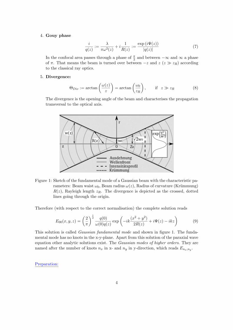
5. Divergence:
ΘDiv := arctan
(ω(z)
z
)= arctan
(ω0
zR
), if z � zR (8)
The divergence is the opening angle of the beam and characterises the propagationtransversal to the optical axis.
Figure 1: Sketch of the fundamental mode of a Gaussian beam with the characteristic pa-rameters: Beam waist ω0, Beam radius ω(z), Radius of curvature (Krummung)R(z), Rayleigh length zR. The divergence is depicted as the crossed, dottedlines going through the origin.
Therefore (with respect to the correct normalisation) the complete solution reads
E00(x, y, z) =
(2
π
) 12 q(0)
ω(0)q(z)exp
(−ik (x2 + y2)
2R(z)+ iΨ(z)− ikz
)(9)
This solution is called Gaussian fundamental mode and shown in figure 1. The funda-mental mode has no knots in the x-y-plane. Apart from this solution of the paraxial waveequation other analytic solutions exist. The Gaussian modes of higher orders. They arenamed after the number of knots nx in x- and ny in y-direction, which reads Enx,ny .
Preparation:
4
1. Calculate the Rayleigh length of the HeNe laser used in this experiment (λ =632.8nm). Assume the beam waist to be ω0 = 0.315 mm. Discribe qualitatively:Where in the beam path is the waist if the resonator is built of a planar and aspherical mirror (Compare section 2).
2. For which values of z is the radius of curvature minimal or maximal respectively?
3. In the experimental setup there are about 3 meters between the resonator andthe wall of the room. What is the beam radius at that distance? Calculate themaximal distance a photodiode (diameter d = 3.5 mm) can be placed at so that itis still possible to catch the entire beam with diameter 2 · ω(z). Is it possible toenlarge this distance using optical elements?
1.2 Stability of a resonator [2]
In a resonator containing spherical mirrors certain conditions must hold in order toachieve a stable resonator. These conditions can be obtained using ray optics (geomet-rical optics). Therefore the beam inside the resonator is considered. It must reproduceitself after a finite number of circulations in the resonator so that a stationary state isformed. In case of the plane parallel resonators for example these beams are orthogonalto the mirrors and reproduce themselves within one circulation.Optical elements like lenses, mirrors and even a bare propagation along the optical axiscan be expressed via ABCD-matrices M as follows:
~a2 = M · ~a1 (10)
using the beam vectors ~ai := (ri, θi), where ri denotes the distance to the optical axisand θi the angle. Looking on the resonator as a periodic system of lenses, it can beexpressed as follows:
M = MR1 ·ML ·MR2 ·ML (11)
Here MRi is the matrix for a spherical mirror with radius Ri and ML is the matrix for apropagation covering the distance L (i.e. the resonator length). The four inputs of thematrix are called A, B, C and D. Then one has:
MRi =
(1 0− 2Ri
1
)(12)
ML =
(1 L0 1
)(13)
The eigenvectors of M form a basis for any random beam vector ~a. For the eigenvaluesone has:
5
λ1,2 =Tr(M)
2±
√(Tr(M)
2
)2
− 1 (14)
In dependence on the discriminant one can differentiate between two cases for the traceof M :
1. |Tr(M)| > 2: Both eigenvalues are real, one is bigger and the other one smallerthan 1. So there are beam vectors, whose magnitude increases every circulationand which exit the resonator at some point. Thus the resonator is unstable.
2. |Tr(M)| ≤ 2: One has: λ1 = λ∗2 and |λi| = 1. The resonator is stable.
The criterion for a stable resonator therefore reads as follows:
|λ1| = |λ2| = 1 (15)
For spherical resonators so called g-parameters are usually introduced giving informationin the radius Ri of the mirror as well as the resonator length L:
g1 = 1− L
R1(16)
g2 = 1− L
R2(17)
Applying definition (16) and (17) to the ABCD-matrices and calculating the trace thereis another criterion for stable resonators:
Tr(M) = A+D = 4 g1 · g2 − 2 (18)
⇐⇒ 0 ≤ g1 · g2 ≤ 1 (19)
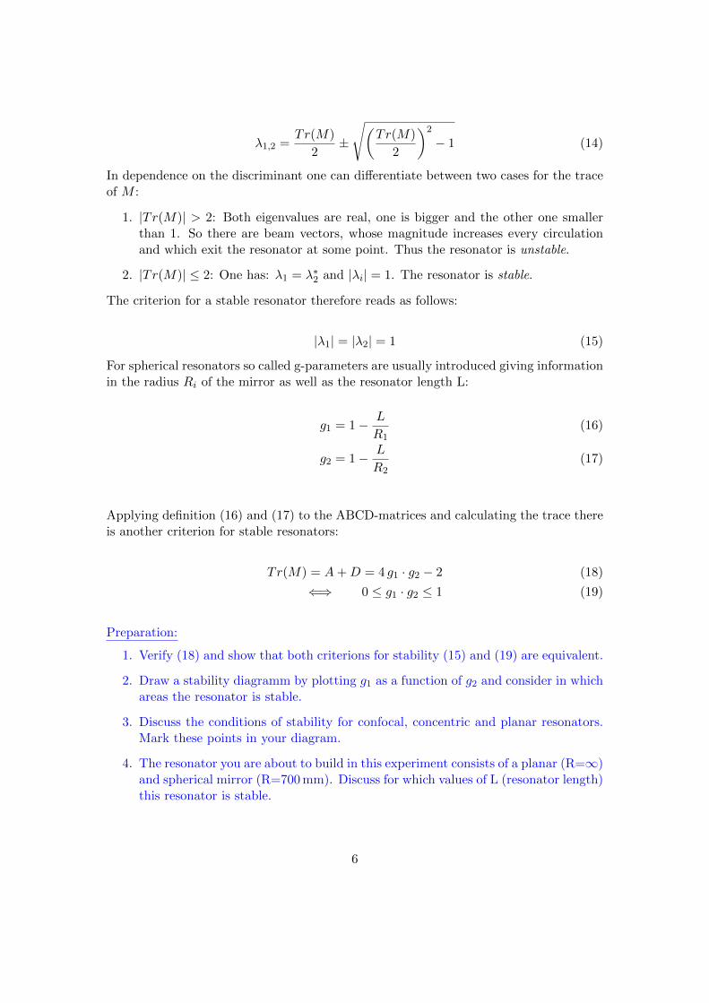
Preparation:
1. Verify (18) and show that both criterions for stability (15) and (19) are equivalent.
2. Draw a stability diagramm by plotting g1 as a function of g2 and consider in whichareas the resonator is stable.
3. Discuss the conditions of stability for confocal, concentric and planar resonators.Mark these points in your diagram.
4. The resonator you are about to build in this experiment consists of a planar (R=∞)and spherical mirror (R=700 mm). Discuss for which values of L (resonator length)this resonator is stable.
6
1.3 Longitudinal Modes [1]
Longitudinal modes are oscillations along the propagation direction. Figurative, one cansee them as wave peaks and throughs separated by half a wave length (Up to 100000in a HeNe Laser). But only certain wave lengths enable stationary waves (i.e. wavesthat have fixed points where the amplitude is constantly zero and that can be lookedat as two waves with same amplitude and frequency propagating in opposite direction).Allowed waves have a frequency property as follows:
ν(N) = N · c2L
(20)
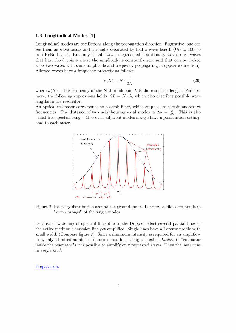
where ν(N) is the frequency of the N-th mode and L is the resonator length. Further-more, the following expressions holds: 2L = N · λ, which also describes possible wavelengths in the resonator.An optical resonator corresponds to a comb filter, which emphasises certain successivefrequencies. The distance of two neighbouring axial modes is ∆ν = c
2L . This is alsocalled free spectral range. Moreover, adjacent modes always have a polarisation orthog-onal to each other.
Figure 2: Intensity distribution around the ground mode. Lorentz profile corresponds to”comb prongs” of the single modes.
Because of widening of spectral lines due to the Doppler effect several partial lines ofthe active medium’s emission line get amplified. Single lines have a Lorentz profile withsmall width (Compare figure 2). Since a minimum intensity is required for an amplifica-tion, only a limited number of modes is possible. Using a so called Etalon, (a ”resonatorinside the resonator”) it is possible to amplify only requested waves. Then the laser runsin single mode.
Preparation:
7
1. Calculate the free spectral range (FSR) of a Helium-Neon-Laser at 632,8 nm, whena resonator length of 60 cm is used.
2. Which resolution does a spectrometer have to have to find out if the laser is insingle mode?
8
2 Setting up the laser
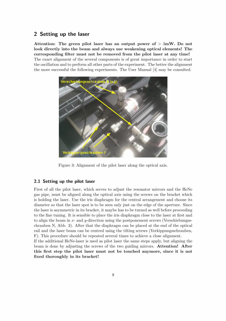
Attention: The green pilot laser has an output power of > 3mW. Do notlook directly into the beam and always use weakening optical elements! Thecorresponding filter must not be removed from the pilot laser at any time!The exact alignment of the several components is of great importance in order to startthe oscillation and to perform all other parts of the experiment. The better the alignmentthe more successful the following experiments. The User Manual [4] may be consulted.
Figure 3: Alignment of the pilot laser along the optical axis.
2.1 Setting up the pilot laser
First of all the pilot laser, which serves to adjust the resonator mirrors and the HeNegas pipe, must be aligned along the optical axis using the screws on the bracket whichis holding the laser. Use the iris diaphragm for the central arrangement and choose itsdiameter so that the laser spot is to be seen only just on the edge of the aperture. Sincethe laser is asymmetric in its bracket, it maybe has to be turned as well before proceedingto the fine tuning. It is sensible to place the iris diaphragm close to the laser at first andto align the beam in x- and y-direction using the postponement screws (Verschiebungss-chrauben N, Abb. 3). After that the diaphragm can be placed at the end of the opticalrail and the laser beam can be centred using the tilting screws (Verkippungsschrauben,F). This procedure should be repeated several times to achieve a close alignment.If the additional HeNe-laser is used as pilot laser the same steps apply, but aligning thebeam is done by adjusting the screws of the two guiding mirrors. Attention! Afterthis first step the pilot laser must not be touched anymore, since it is notfixed thoroughly in its bracket!
9
2.2 Laser tube alignment
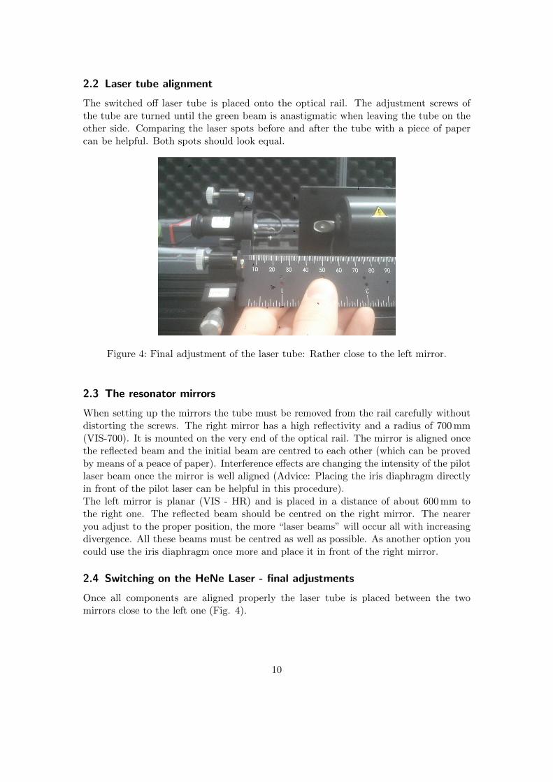
The switched off laser tube is placed onto the optical rail. The adjustment screws ofthe tube are turned until the green beam is anastigmatic when leaving the tube on theother side. Comparing the laser spots before and after the tube with a piece of papercan be helpful. Both spots should look equal.
Figure 4: Final adjustment of the laser tube: Rather close to the left mirror.
2.3 The resonator mirrors
When setting up the mirrors the tube must be removed from the rail carefully withoutdistorting the screws. The right mirror has a high reflectivity and a radius of 700 mm(VIS-700). It is mounted on the very end of the optical rail. The mirror is aligned oncethe reflected beam and the initial beam are centred to each other (which can be provedby means of a peace of paper). Interference effects are changing the intensity of the pilotlaser beam once the mirror is well aligned (Advice: Placing the iris diaphragm directlyin front of the pilot laser can be helpful in this procedure).The left mirror is planar (VIS - HR) and is placed in a distance of about 600 mm tothe right one. The reflected beam should be centred on the right mirror. The neareryou adjust to the proper position, the more “laser beams” will occur all with increasingdivergence. All these beams must be centred as well as possible. As another option youcould use the iris diaphragm once more and place it in front of the right mirror.
2.4 Switching on the HeNe Laser - final adjustments
Once all components are aligned properly the laser tube is placed between the twomirrors close to the left one (Fig. 4).
10
The pilot laser is not needed anymore and should be switched off. The current supply ofthe tube is switched on. Ideally the laser will start immediately. If not, slightly sway theupper adjustment screw until the laser lights up. If there is still no oscillation, swivelthe upper screw periodically back and forth while turning the lower one in one directiononly. If there is no oscillation try the other direction.When the laser lights up, turn the adjustment screws to achieve stable oscillation. Afterthat the photodiode is placed in front of one of the Brewster windows (using holder E)and connected to the oscilloscope. Then an optimisation of the output power can beachieved by further twists of the screws. Use the photodetector connecting device (P)for connecting the diode to the oscilloscope and choose the highest resistance.If the laser does not work it is recommended to do the whole fine adjustment once again.This sould be done quickly since all components are already preset.Only if there is still no oscillation the mirrors can be cleaned carefully and only underthe guidance of the supervisor.
3 Installation of a Littrow Prism
Caution: This set-up is not needed until you reach task 4.5!
3.1 Information
Installing a Littrow prism (L) instead of the planar mirror allows the oscillation of adifferent wavelength (611,8 nm, transition 3s2 → 2p6). The goal is to examine this linespectroscopically and to compare it to the main line (632,8 nm).The Littrow’s Prism Tuner (LTP) is a combined optical component consisting of a prismand a reflecting coating. It acts as laser mirror and selective element simultaneously. Itoperates as laser mirror and also as wavelength selective instrument.For a successful installation a precise set up of all laser components (in usual mirrorconfiguration) is crucial which allows maximised power output. If needed consult theuser manual [4] available in the laboratory.
Caution: Do not touch the surface of the prism at any time! Dust, grease or scratchescould damage the instrument and impair its functionality.
3.2 Installation of the prism and oscillation of the orange line (611.8 nm)
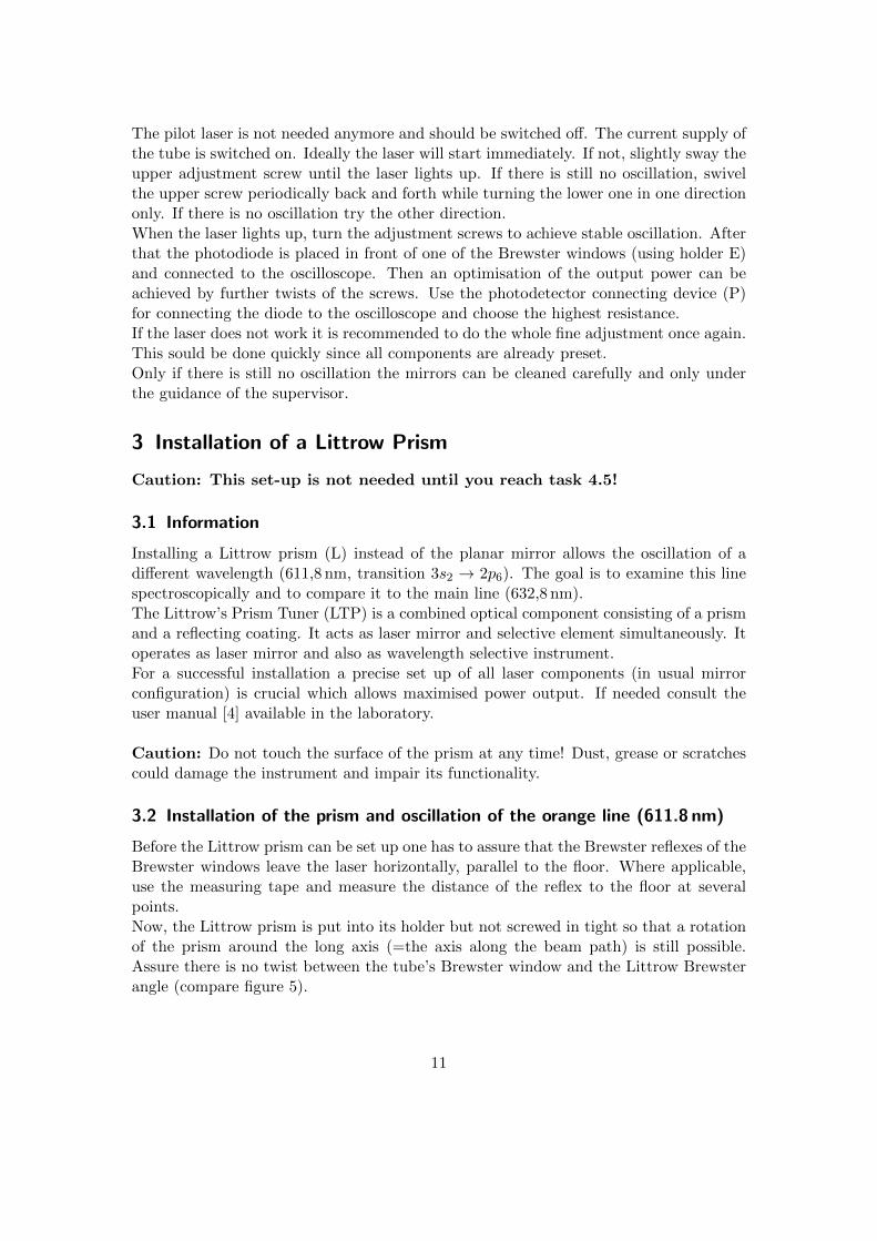
Before the Littrow prism can be set up one has to assure that the Brewster reflexes of theBrewster windows leave the laser horizontally, parallel to the floor. Where applicable,use the measuring tape and measure the distance of the reflex to the floor at severalpoints.Now, the Littrow prism is put into its holder but not screwed in tight so that a rotationof the prism around the long axis (=the axis along the beam path) is still possible.Assure there is no twist between the tube’s Brewster window and the Littrow Brewsterangle (compare figure 5).
11
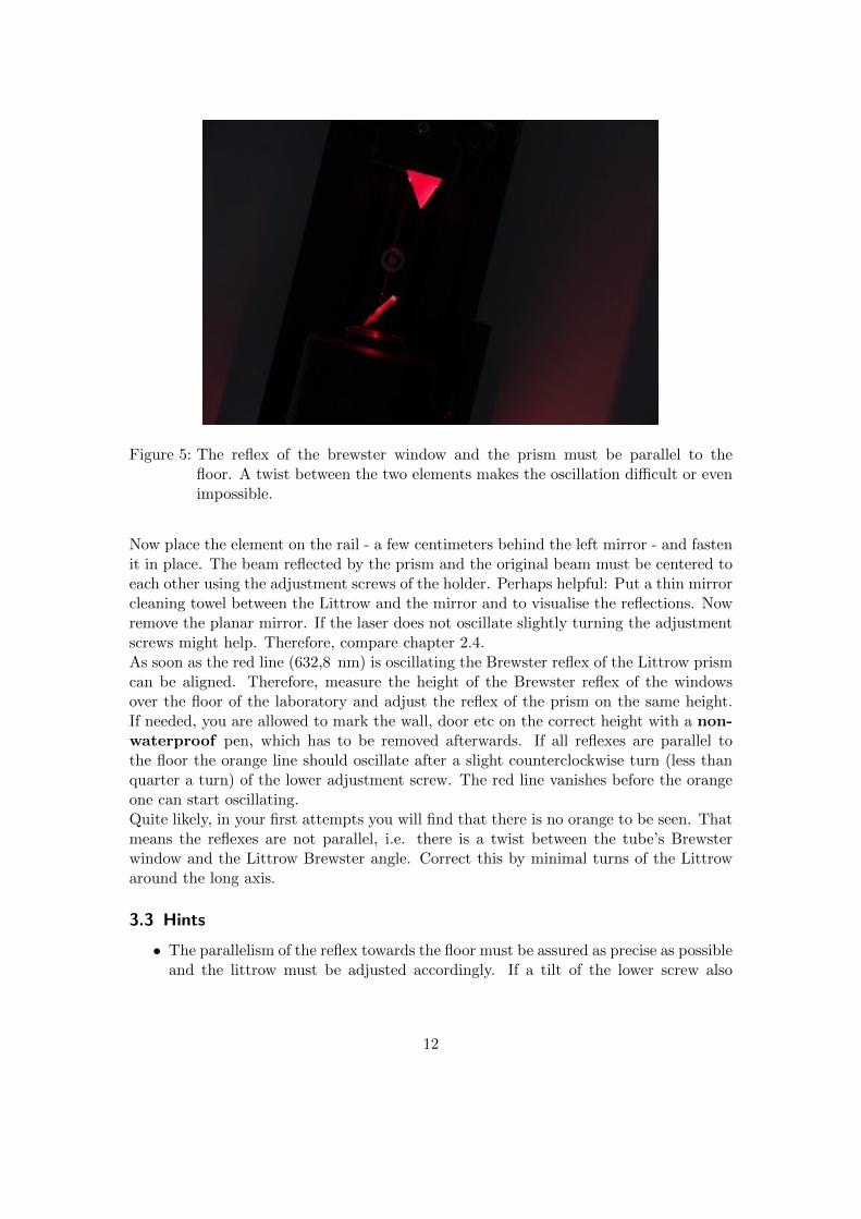
Figure 5: The reflex of the brewster window and the prism must be parallel to thefloor. A twist between the two elements makes the oscillation difficult or evenimpossible.
Now place the element on the rail - a few centimeters behind the left mirror - and fastenit in place. The beam reflected by the prism and the original beam must be centered toeach other using the adjustment screws of the holder. Perhaps helpful: Put a thin mirrorcleaning towel between the Littrow and the mirror and to visualise the reflections. Nowremove the planar mirror. If the laser does not oscillate slightly turning the adjustmentscrews might help. Therefore, compare chapter 2.4.As soon as the red line (632,8 nm) is oscillating the Brewster reflex of the Littrow prismcan be aligned. Therefore, measure the height of the Brewster reflex of the windowsover the floor of the laboratory and adjust the reflex of the prism on the same height.If needed, you are allowed to mark the wall, door etc on the correct height with a non-waterproof pen, which has to be removed afterwards. If all reflexes are parallel tothe floor the orange line should oscillate after a slight counterclockwise turn (less thanquarter a turn) of the lower adjustment screw. The red line vanishes before the orangeone can start oscillating.Quite likely, in your first attempts you will find that there is no orange to be seen. Thatmeans the reflexes are not parallel, i.e. there is a twist between the tube’s Brewsterwindow and the Littrow Brewster angle. Correct this by minimal turns of the Littrowaround the long axis.
3.3 Hints
• The parallelism of the reflex towards the floor must be assured as precise as possibleand the littrow must be adjusted accordingly. If a tilt of the lower screw also
12
induces some vertical movement it will stop the laser from going orange. Thelower screw should only swivel the Littrow horizontally.
• A good alignment is achieved if by shifting the Littrow along the rail the red linekeeps oscillating. Then one is headed in the right direction.
• If you try to turn from red to orange slightly wobbling the upper screw might behelpful in some cases.
Preparation: Why is it crucial to have parallel alignment of Brewster reflexes?
4 Experiment and analysis
4.1 Measurement of the Gaussian beam
In this part all parameters of the Gaussian beam (compare chapter 1.1) areto be determined for two different resonator lengths. Choose two resonatorlengths with at least 10 cm difference.
4.1.1 Scanning Knife Edge Method
Experiment:
1. Make sure that the excited mode is the Gaussian ground mode.
2. Deflect the beam by the use of mirrors, so that the maximum space on the tableis used.
3. Put the photodiode (D) with a mount (C) in the beam an connect it via the resistorto the oscilloscope. For large distances from the resonator end to the photodiodeit may be useful to focus the beam with a lens onto the photodiode.
4. Do the following measurements for 3 reasonable distances zi from the beam waist tothe razor blade (R): Measure the voltage U (representing the whole beam intensity)in dependency of the lateral movement x of the razor blade. It may be useful toturn off the ceiling lights for this measurement.
5. Repeat the measurements for a another resonator length, which differs at least 10cm from the previous one.
Analysis:
1. Fit the antiderivative of a Gaussian distribution to the measured values Ui(x). Byusing an adequate fit function you will find the beam diameter ωi for each distancezi. Why the antiderivative and not the Gaussian function?Hint: most data evaluation softwares like qti-plot or gnuplot have an in-builtfunction erf(x).
13
2. Determine from the fit-data the values wi, at which the intensity of the beam dropsto 1/e of the maximum value.
3. Now that you have three values ωi, think of a suitable fit function for ω(z) anddetermine from this fit the Rayleigh length as well as the beam waist. How canpossible determinations be explained?
4. Make plots of the beam radius, the radius of curvature and the divergence. Markthe Rayleigh zone and explain if the photodiode was in the far field of the resonatoror not.
5. Do the same evaluation for the other resonator length. How does the the Rayleighlength and beam waist change and why?
4.1.2 Clip Level Method
Explanations:Similarly to the Scanning Knife-Edge Method a razor blade is scanned perpendicularlyinto the beam and the transmitted laser power is recorded. However, here a so calledclip width Dc is chosen. It defines the distance between two positions of the blade wherethe transmitted power is between εP0 and (1− ε)P0, with ε ∈ (0; 0.5). The Choice of Dc
and the clip level ε depends on the beam profile. If only symmetric profiles get examinedlike in this experiment the clip level can be related to the clip width as follows:
ε =1
2
(1−
∫ +Dc/2
−Dc/2dx
∫ ∞∞
dy I(x, y)
)(21)
To connect the clip width to the beam width ω in scan direction the scale factor S = Dc/σis required. It should be a value appropriate a TEM00 gaussian fundamental mode forwhich the radius is specified as 2ω. This then matches the 1/e2-definition of the beamradius given in 1.1 [6].A too low clip level is inappropriate due to noise and limited detector sensibility. Thechoice for ε should therefore be a value between 0,085 and 0,116 [6]. For a TEM00
gaussian beam the total beam diameter D is 2 times the beam radius w. The latter canbe determined by knowing the clip width Dc and the corresponding scale factor. Thefollowing relation holds:
ε =1
2
(1− erf
(Dc
2√
2ω
))(22)
As there is no analytic expression for the error function you may use a table of valuesto find S.
Experiment:
14
1. Make sure that the mode you can see is the fundamental mode of a Gaussian beam(e.g. using a piece of paper).
2. Deflect the beam using the mirrors (M with holders H), so that you can use themaximum space on the table.
3. Place the photodiode (D with holder C) in the beam far away from the beam waistand connect to the oscilloscope. Describe why it is sensible to focus the beam ontothe diode using a lens (B).Attention: Using focussing elements the intensity of the beam increasessignificantly! Therefore never look into the optical path!
4. Choose an appropriate clip level (according to [6], e.g. ε = 0.1)
5. Measure the clip width Dc using the razor blade (R) for the distance z chosen inthe task before. So, you will measure the distance of those points where the poweris between εP0 and (1− ε)P0. Repeat this several times in order to reduce errors.
6. Repeat the measurements for a another resonator length, which differs at least 10cm from the previous one.
Analysis:
1. From your measured clip widths and the corresponding scale factors calculate thestandard deviations of the gaussian beam profile and from that calculate the radiusw(z).
2. For large distances from the waist the beam radius is approximately linear to z.Use this property and apply an appropriate fit in order to determine the functionω(z) and the Rayleigh length as well as the beam waist.
3. Draw up plots of the beam radius, the radius of curvature and the divergence.Mark the confocal area. Work out if the photodiode was placed in the far field ofthe laser or not.
4. Compare the results from both lengths. Which differences do you detect? Consultthe theory on beam profiles and its parameters to explain them.
4.2 Stability of the laser resonator
Now the stability of the laser resonator is examined experimentally and compared to thetheoretical predictions made in the preparation.
Experiment
1. Consider if there is a difference in moving the right mirror or the left one. Explainwhy.
15
2. Use the photodiode once more and place it in front of the right mirror (outside theresonator of course).
3. Vary the distance between the mirrors in sensible intervals by moving one mirroruntil you reach the point where the oscillation discontinues. For each distance notethe voltage. Attention: Moving the mirrors on the optical rail can cause the laserto not start up again even though the stability criterion is fulfilled. Slightly “jiggle”the mirror can help. Therefore it is sensible to consider until which distance L ofthe mirrors the laser is stable.
Analysis
• Calculate the g-factors of the mirrors using the radii R1 = ∞ and R2 = 700µmand mark them on your stability diagramm.
• Descriptively explain the behaviour of the voltage as a function of the resonatorlength L.
• Plot the behaviour of the voltage as a function of g2 of the right mirror anddetermine the value of g2 at the maximum resonator length. Thereby, quantifypotential deviations of the radius R2 from the manufacturer information of 700 mm.
4.3 Measurement of the coherence length using a Michelson interferometer
For the next subtask it is advisable to place the right mirror at the very end of the rail.
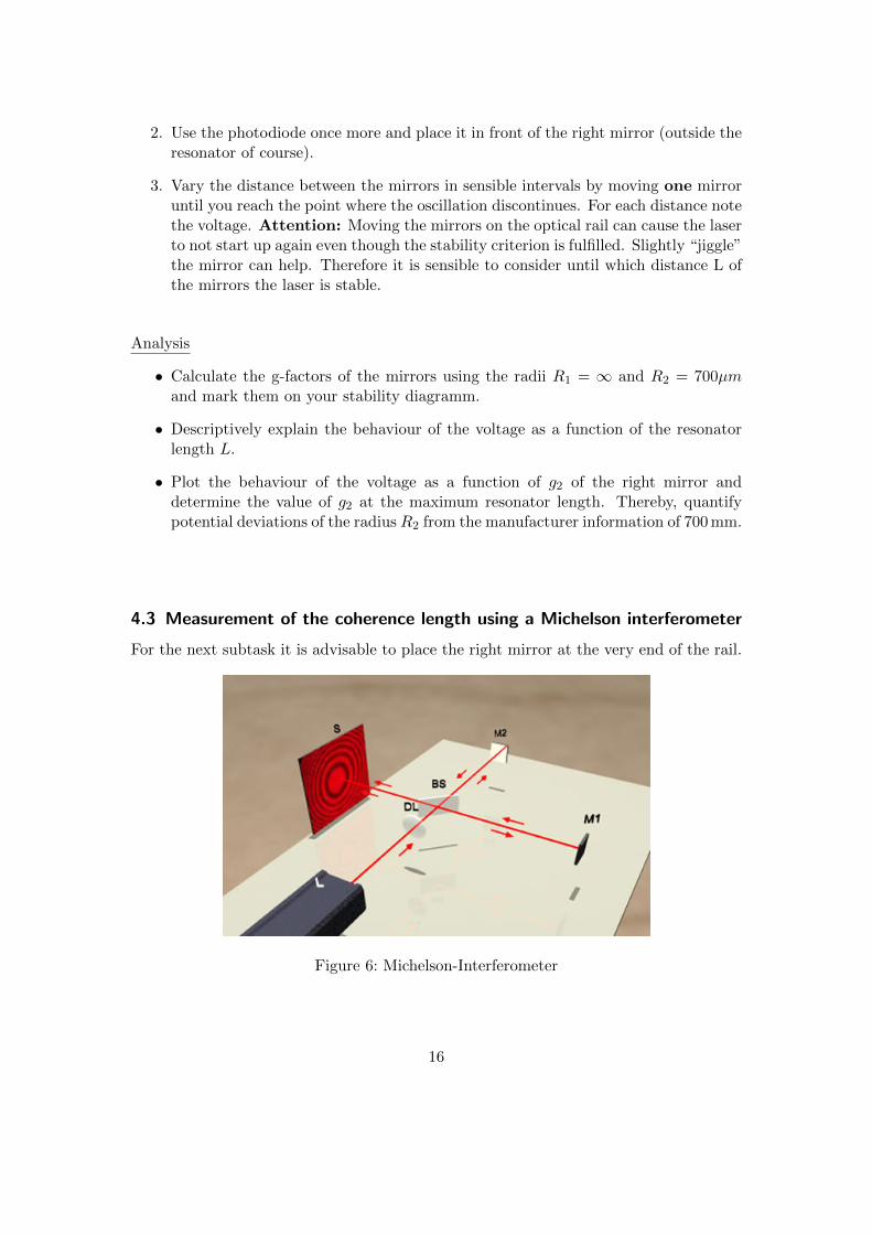
Figure 6: Michelson-Interferometer
16
A Michelson-Interferometer consists of a beam splitter BS, two mirrors and a screen,that are arranged as shown in figure 6. The laser beam hits the beam splitter whichallows one part to pass through while the other one is reflected. The two beams hit M1and M2 respectively where both beams get reflected again and sent back towards thebeam splitter. Another reflection/transmittance sends both beams to the screen wherethey interfere according to their path difference. Please note: In this experiment thelabels M1 and M2 respectively only serve as a numbering. Both mirrors are identical!The path difference is the additional distance one beam has to cover on its way to thescreen compared to the other beam.
∆L = 2 · (dM1 − dM2)
Here dM1 and dM2 denote the distances between the mirrors and the beam splitter.The path difference for both beams is
τ =∆L
c.
∆L = 2 · (dM1 − dM2)
Experiment
1. Align both mirrors and the beam splitter behind the laser so that the angle betweenthe beam paths is 90◦ and that there are interference rings to be seen (when∆L = 0). Make sure that the beams are horizontal (use a ruler). With an almostperfect adjustment at least interference lines can be obtained.Advice: After setting up the beam splitter you can use a piece of paper to checkif the the primary and the reflected beam are centred to each other.
2. Now move the rear mirror. Up to which path difference can you obtain interference?What does that mean for the coherence length? You can use the opposite wall or awhite paper in appropriate distance. If you are not able to see interference anymoreyou can try widening the beam using a lens (A) placed before the Interferometer.
3. What can you tell about the width of the interference rings and distances betweenthe maxima and the minima? How can you justify this?
4. Explain now why it was sensible to place the right mirror at the very end of therail, i.e. to choose a great resonator length!
17
4.4 Higher transverse modes (optional)
In this part the aim is to suppress the fundamental Gaussian mode to allow highermodes. This is achieved by covering the centre of the beam. Therefore, wires of differentthickness are used which are placed in the beam path between the resonator mirrors.There are thicknesses of 20µm and 100µm available. The wires are held in a circularholder (K) which has to be placed next to the rail and screwed tight.
Experiment
1. Using the different wires try to induce higher order transversal modes (TEM10,TEM01, TEM11, etc). Explain what happens when the wire is driven into thebeam path.
2. Try to experimentally explain the influence of mirror distance, wire position aswell as position of the tube inside the resonator on the result.
3. When a higher mode oscillates: Via the oscilloscope observe intensity changes ofthe laser beam leaving the laser and of the brewster reflex. Compare to the valuesfor the fundamental mode.
4.5 Spectroscopic Examinations (optional)
For this experiment it is necessary to set up the Littrow Prism as described in chapter 3.Furthermore, the blue fibre optic is needed as well as its holder, the grating spectrometerRed Tube USB 650 and the laptop with the software OceanView.
Experiment
1. Screw in the fibre optic into the corresponding holder (F) and connect it to thespectrometer. Please make sure not to bend the fibre too much, since it can easilybe damaged. Put the fibre into the beam path behind the right mirror and switchon the laser showing the red line oscillating. Since intensity can be quite high,indirect observation is recommended. Shield the fibre from direct irradiation with4-5 layers of mirror cleaning cloth. You can also use the mirror holders (H) forthat purpose.
2. Adjust the Integration Time of the software so that the signal stays within thedisplay (Aquisition Group Window → Integration Time: Auto).
3. Take spectra of the red and orange line using the same integration time. Further-more take a spectrum of the light coming from the tube as well as of the ceilinglighting. Doing so you’ll probably have to adjust the integration time once more.Take this down and explain its influence on the measurement.
18
4. Finally, by the help of the diode, measure the intensity at the Brewster and behindthe right mirror. Exchange the prism for the planar mirror again and repeat themeasurement. Put down your observations.
Analysis
1. Which lines can be found in the spectrum of the gas discharge? Compare it tothe spectrum of the ceiling lighting and explain why especially in this part of theexperiment it is crucial to switch off the lighting.
2. How is the oscillation of the orange line possible? Explain the difference betweenthe red and the orange line regarding intensity and resolution. Determine the exactposition (View Spectrum Peaks → Centre Position) and compare to theoreticalexpectations.
3. Research if other lines could possibly oscillate and if additional equipment isneeded.
4. Determination of the resolution of the spectrometer (View Spectrum Peaks →FWHM (No smoothing)): With this experimental setup, can you clarify if thelaser works in single mode?
5. How do you explain the differences in the voltage using the Littrow compared tothe planar mirror?
19
References
[1] F.K.Kneubuhl, M.W.Sigrist: Laser, 7.Auflage, Vieweg und Teubner, Wiesbaden,2008
[2] Prof. Dr. Hans-Jorg Kull: Laserphysik - Physikalische Grundlagen des Laserlichtsund seine Wechselwirkung mit Materie, Oldenbourg Verlag Munchen, 2010
[3] Dieter Meschede: Optik, Licht und Laser, 2. Auflage, Vieweg und Teubner, Wies-baden 2005
[4] Leybold: P5.8.5.5 - Helium Neon Laser, User manual,www.photonics.ld-didactic.de/Manuals/4747104_EN%20HeNe%20Laser.pdf
[5] Durham Atomic and Molecular Physics, Gaus-sian Beams and the Knife-Edge Measurement,http://massey.dur.ac.uk/resources/grad_skills/KnifeEdge.pdf
[6] Anthony E. Siegman, M.W. Sasnett, T.F. Johnston, Jr, Choice of Clip Levelsfor Beam Width Measurements Using Knife-Edge Techniques, IEEE Journal ofQuantum Electronics, Vol 27, No 4, April 1991
20
Appendix
SpectrometerWith the help of the grating spectrometer (Red Tide USB-650 ) emission spectra ofvarious light sources get examined (atomic spectra, thermal light sources, energy savinglamps, LEDs, etc). In a grating spectrometer light of different wavelengths λ is deflecteddifferently. Main maxima of the intensity occur at angles for which the optical pathdifference is an integer multiple (m) of the wavelength.
g sin θ = mλ
In the spectrometer used in this experiment the light to be examined is brought to theentrance slit with the help of fibre optics. A mirror focusses the light onto a grating(Compare figure 7). By means of a second mirror the first diffraction order of the gratingis reflected onto a CCD-row containing 650 pixels, which transform the optical signal intodigital signals. For the purpose of control and data capture the spectrometer is connectedto the computer via USB. For controlling and displaying the software OceanView is used.
21
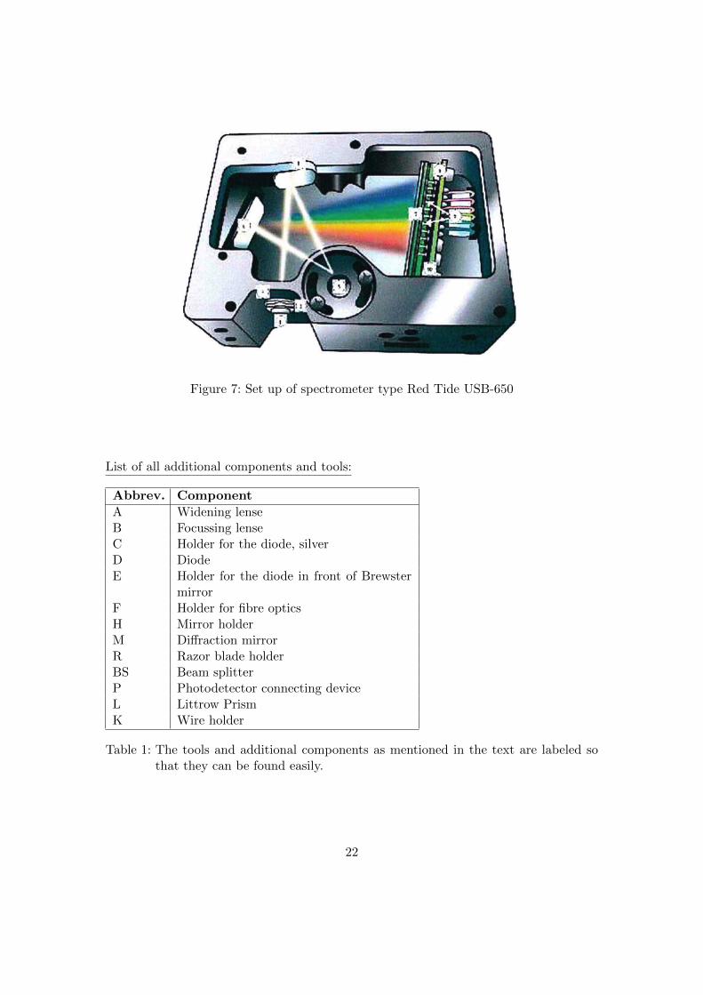
Figure 7: Set up of spectrometer type Red Tide USB-650
List of all additional components and tools:
Abbrev. Component
A Widening lenseB Focussing lenseC Holder for the diode, silverD DiodeE Holder for the diode in front of Brewster
mirrorF Holder for fibre opticsH Mirror holderM Diffraction mirrorR Razor blade holderBS Beam splitterP Photodetector connecting deviceL Littrow PrismK Wire holder
Table 1: The tools and additional components as mentioned in the text are labeled sothat they can be found easily.
22