Embed Size (px)
Citation preview
GV3linear guidance and transmission system
HepcoMotion®
GV3 Benefits
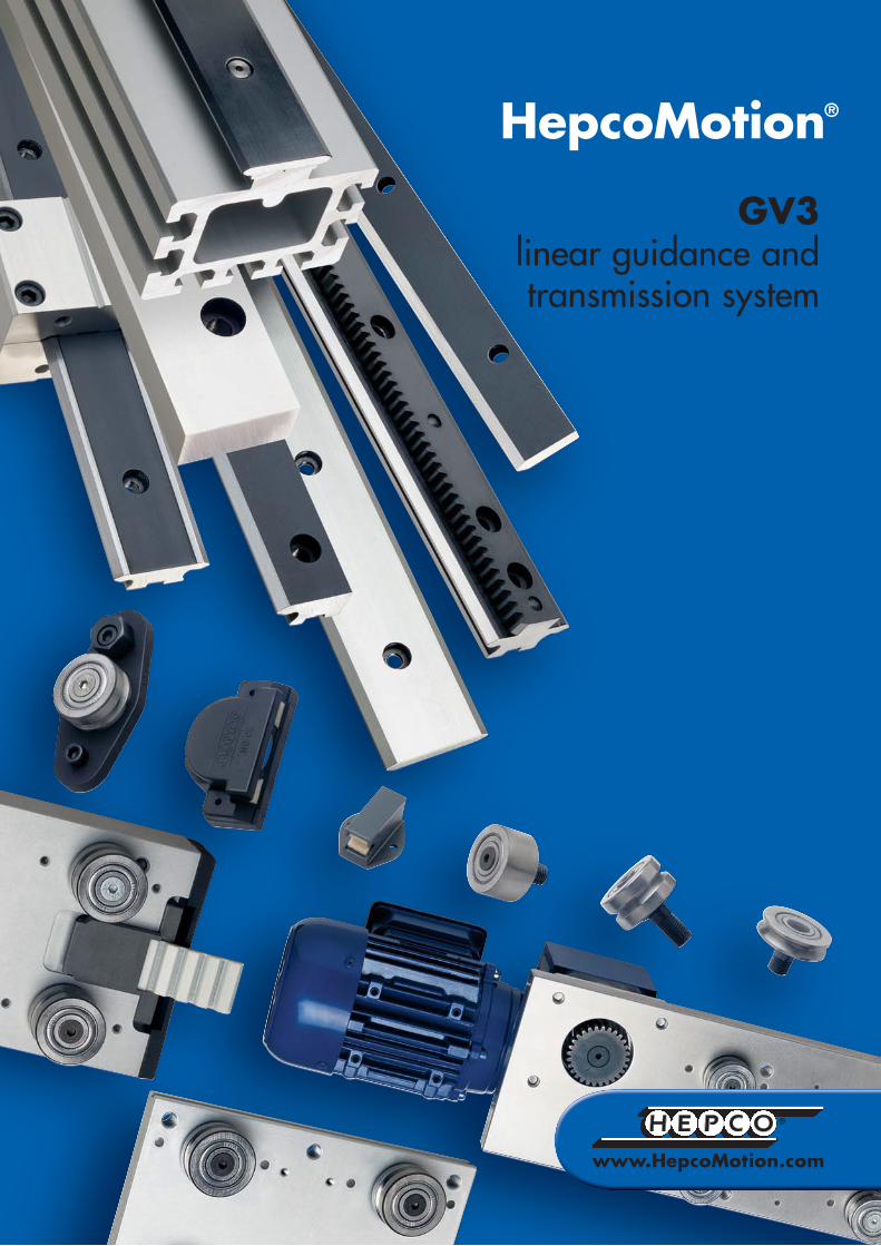
Introducing the GV3 linear guidance and transmission systemThe GV3 linear guidance and transmission system has been designed to provide the customer with an unrivalled choice of sizes and options to cater for virtually every linear motion requirement.
In devising GV3, Hepco have retained the best features of their highly successful Generation 2 and CM Slide Systems in a greatly expanded range. Many new components have been added including Single Edge Slides, Flat Tracks and drive options.
Customers may now choose Slides from three grades of precision and combine them with either Twin Bearings, Double Row Bearings or low cost Slimline Bearings. This enables the ideal system to be specified for optimum performance within the budget available.
The reliability of Hepco’s all steel slideway and V bearing concept has been proved conclusively over nearly fifty years. Improvements are continually being made to this fundamentally sound design resulting in a truly evolutionary system for the 21st century.
By choosing GV3, customers can be assured of a quality and performance which surpasses all expectations.
SMOOTH: High accuracy and fine finish of components ��� allows constant driving force without vibration. Friction free motion ��� allows smaller, lower cost motors to be selected. FAST: Optimised Bearing and Slide interface design ��� enables very high speeds with low wear. Low stick friction and low inertia of Bearing rotation ��� allows fast acceleration for shortest stroke.ACCURATE: High degree of Slide parallelism and minimum Bearing clearance ��� results in virtually zero play. Important dimensions accurately controlled ��� for reliable system height and positional accuracy.QUIET: Specially designed Bearing and Slide geometry ��� results in one of the quietest slide systems available.DURABLE: All steel Slideway ��� three times stiffer than composite aluminium slide systems. Rugged construction ��� suits high duty applications and harsh environments. Lubrication devices available ��� maximises life with no relubrication necessary in most instances. Unique wiping action ��� expels debris in environments where other systems fail. Compliant bearing design ��� for tolerance of misalignment. Reliable performance confirmed by testing ��� specify Hepco with confidence.SIMPLE: Easily understood proven technology ��� little to go wrong and simple to maintain.VERSATILE: Huge range of sizes, types and ancillary components available ��� provides solution to most design problems. Long lengths available up to 4 m in most sizes ��� saves on assembly time. Available as assembled unit or in component form ��� provides maximum flexibility of design. Works in any plane and orientation ��� unrestricted use in machine construction. Operates without lubrication ��� ideal for food machinery and clean applications. Driven systems available ��� complete solutions from a single source saves design and administration time.ECONOMIC: Choice of Slide precision and bearing design ��� to match cost/performance requirements. Designed for minimum installation time ��� significantly reduces cost.
How To Use This CatalogueThe GV3 product range is large, so to help readers find their way around the catalogue, the following aids have been devised:
Cap Seals Blue ‘Hypertext’
Throughout the catalogue, key words have been picked out in Blue ‘Hypertext’. Where this appears, look for a Page Icon to direct you to other related pages.
Page Icons are located on the outside edge of pages in alphabetical order. They include a picture of a component or catalogue section which is related to the subject under discussion, together with a page number. This acts as a quick index.
Page Icons
1
Cap SealsP 36
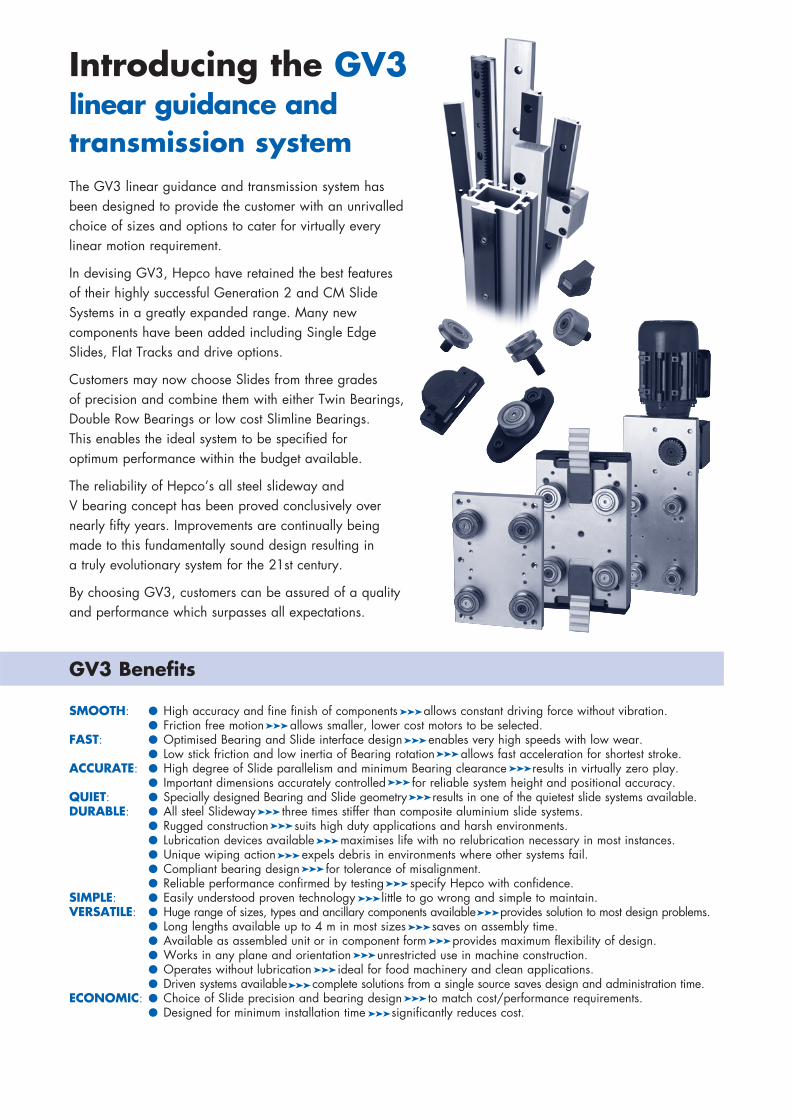
Contents Page
System Composition 2-7
Application Examples 8-16
System Selector 17
Data and Dimensions for Individual Components
Carriages, Carriage Locking Device and Shock Absorber Fixing Blocks 18-23
‘V’ Slides 24-29
Slide Beams 30-31
‘V’ Bearings 32-35
Cap Seals, Cap Wipers and Lubricators 36-38
Flange Clamps 39
Flat Tracks 40
Track Rollers 41-43
Racks 44
Pinions 45
Belt Driven Carriages, Belts & Pulleys 46-47
Rack Driven Carriages 48-49
Gearboxes, AC Geared Motors & Flanges 50-51
AC Speed Controller & Ancillary Components 52-53
Data and Dimensions for Assembled Systems
‘V’ Slide Systems 54-55
Systems with Track Rollers, Racks & Pinions 56-57
Technical DataLoad/Life Calculations and Examples 58-62
Deflection of Self-Supporting Slides 63
Drive Calculations for Rack Driven Carriages 64-65
System Assembly and Adjustment 66-67
Technical Specifications 68
FOR AMENDMENTS & UPDATES VISIT www.HepcoMotion.com and select literature button
System Composition
2
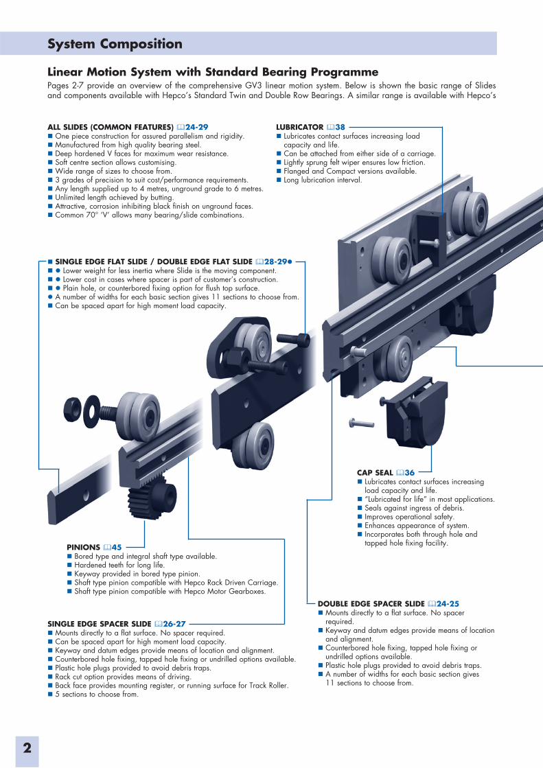
Linear Motion System with Standard Bearing ProgrammePages 2-7 provide an overview of the comprehensive GV3 linear motion system. Below is shown the basic range of Slides and components available with Hepco’s Standard Twin and Double Row Bearings. A similar range is available with Hepco’s
CAP SEAL 36Lubricates contact surfaces increasing
load capacity and life.“Lubricated for life” in most applications.Seals against ingress of debris.Improves operational safety.Enhances appearance of system.Incorporates both through hole and
tapped hole fixing facility.
LUBRICATOR 38Lubricates contact surfaces increasing load
capacity and life.Can be attached from either side of a carriage.Lightly sprung felt wiper ensures low friction.Flanged and Compact versions available.Long lubrication interval.
PINIONS 45Bored type and integral shaft type available.Hardened teeth for long life.Keyway provided in bored type pinion.Shaft type pinion compatible with Hepco Rack Driven Carriage.Shaft type pinion compatible with Hepco Motor Gearboxes.
SINGLE EDGE SPACER SLIDE 26-27Mounts directly to a flat surface. No spacer required.Can be spaced apart for high moment load capacity.Keyway and datum edges provide means of location and alignment.Counterbored hole fixing, tapped hole fixing or undrilled options available.Plastic hole plugs provided to avoid debris traps.Rack cut option provides means of driving.Back face provides mounting register, or running surface for Track Roller.5 sections to choose from.
ALL SLIDES (COMMON FEATURES) 24-29One piece construction for assured parallelism and rigidity.Manufactured from high quality bearing steel.Deep hardened V faces for maximum wear resistance.Soft centre section allows customising.Wide range of sizes to choose from.3 grades of precision to suit cost/performance requirements.Any length supplied up to 4 metres, unground grade to 6 metres.Unlimited length achieved by butting.Attractive, corrosion inhibiting black finish on unground faces.Common 70° ‘V’ allows many bearing/slide combinations.
DOUBLE EDGE SPACER SLIDE 24-25Mounts directly to a flat surface. No spacer
required.Keyway and datum edges provide means of location
and alignment.Counterbored hole fixing, tapped hole fixing or
undrilled options available.Plastic hole plugs provided to avoid debris traps.A number of widths for each basic section gives
11 sections to choose from.
SINGLE EDGE FLAT SLIDE / DOUBLE EDGE FLAT SLIDE 28-29Lower weight for less inertia where Slide is the moving component.Lower cost in cases where spacer is part of customer’s construction.Plain hole, or counterbored fixing option for flush top surface.
A number of widths for each basic section gives 11 sections to choose from.Can be spaced apart for high moment load capacity.
System Composition
3
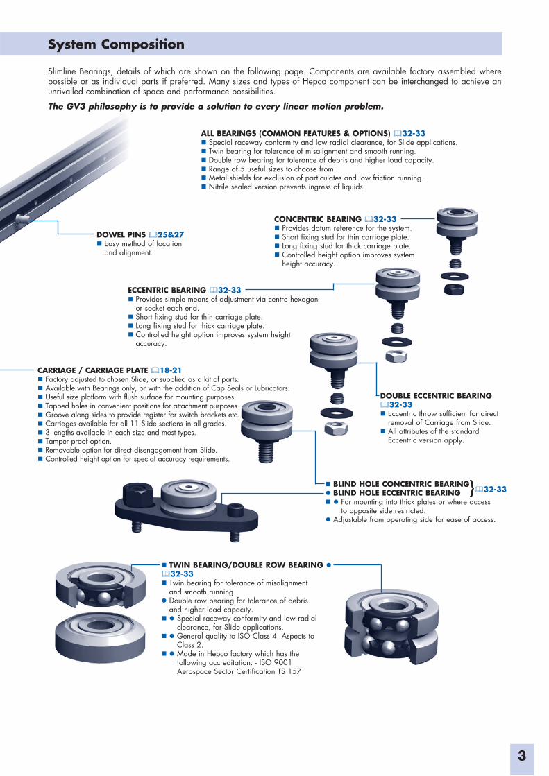
Slimline Bearings, details of which are shown on the following page. Components are available factory assembled where possible or as individual parts if preferred. Many sizes and types of Hepco component can be interchanged to achieve an unrivalled combination of space and performance possibilities.
The GV3 philosophy is to provide a solution to every linear motion problem.
ALL BEARINGS (COMMON FEATURES & OPTIONS) 32-33Special raceway conformity and low radial clearance, for Slide applications.Twin bearing for tolerance of misalignment and smooth running.Double row bearing for tolerance of debris and higher load capacity.Range of 5 useful sizes to choose from. Metal shields for exclusion of particulates and low friction running.Nitrile sealed version prevents ingress of liquids.
CONCENTRIC BEARING 32-33Provides datum reference for the system.Short fixing stud for thin carriage plate.Long fixing stud for thick carriage plate.Controlled height option improves system
height accuracy.
ECCENTRIC BEARING 32-33Provides simple means of adjustment via centre hexagon
or socket each end.Short fixing stud for thin carriage plate.Long fixing stud for thick carriage plate.Controlled height option improves system height accuracy.
DOUBLE ECCENTRIC BEARING32-33Eccentric throw sufficient for direct
removal of Carriage from Slide.All attributes of the standard
Eccentric version apply.
BLIND HOLE CONCENTRIC BEARINGBLIND HOLE ECCENTRIC BEARING
For mounting into thick plates or where accessto opposite side restricted.
Adjustable from operating side for ease of access.
CARRIAGE / CARRIAGE PLATE 18-21Factory adjusted to chosen Slide, or supplied as a kit of parts.Available with Bearings only, or with the addition of Cap Seals or Lubricators.Useful size platform with flush surface for mounting purposes.Tapped holes in convenient positions for attachment purposes.Groove along sides to provide register for switch brackets etc.Carriages available for all 11 Slide sections in all grades. 3 lengths available in each size and most types.Tamper proof option.Removable option for direct disengagement from Slide.Controlled height option for special accuracy requirements.
DOWEL PINS 25&27Easy method of location
and alignment.
TWIN BEARING/DOUBLE ROW BEARING 32-33Twin bearing for tolerance of misalignment
and smooth running.Double row bearing for tolerance of debris
and higher load capacity.Special raceway conformity and low radial
clearance, for Slide applications.General quality to ISO Class 4. Aspects to
Class 2.Made in Hepco factory which has the
following accreditation: - ISO 9001 Aerospace Sector Certification TS 157
32-33}
System Composition
4
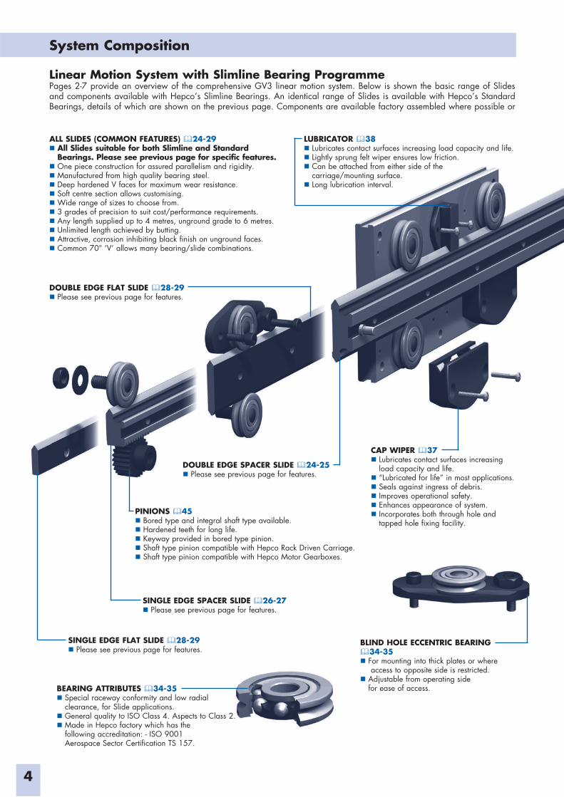
Linear Motion System with Slimline Bearing ProgrammePages 2-7 provide an overview of the comprehensive GV3 linear motion system. Below is shown the basic range of Slides and components available with Hepco’s Slimline Bearings. An identical range of Slides is available with Hepco’s Standard Bearings, details of which are shown on the previous page. Components are available factory assembled where possible or
DOUBLE EDGE FLAT SLIDE 28-29Please see previous page for features.
ALL SLIDES (COMMON FEATURES) 24-29All Slides suitable for both Slimline and Standard
Bearings. Please see previous page for specific features.One piece construction for assured parallelism and rigidity.Manufactured from high quality bearing steel.Deep hardened V faces for maximum wear resistance.Soft centre section allows customising.Wide range of sizes to choose from.3 grades of precision to suit cost/performance requirements.Any length supplied up to 4 metres, unground grade to 6 metres.Unlimited length achieved by butting.Attractive, corrosion inhibiting black finish on unground faces.Common 70° ‘V’ allows many bearing/slide combinations.
LUBRICATOR 38Lubricates contact surfaces increasing load capacity and life.Lightly sprung felt wiper ensures low friction.Can be attached from either side of the
carriage/mounting surface.Long lubrication interval.
SINGLE EDGE SPACER SLIDE 26-27Please see previous page for features.
DOUBLE EDGE SPACER SLIDE 24-25Please see previous page for features.
SINGLE EDGE FLAT SLIDE 28-29Please see previous page for features.
PINIONS 45Bored type and integral shaft type available.Hardened teeth for long life.Keyway provided in bored type pinion.Shaft type pinion compatible with Hepco Rack Driven Carriage.Shaft type pinion compatible with Hepco Motor Gearboxes.
CAP WIPER 37Lubricates contact surfaces increasing
load capacity and life.“Lubricated for life” in most applications.Seals against ingress of debris.Improves operational safety.Enhances appearance of system.Incorporates both through hole and
tapped hole fixing facility.
BEARING ATTRIBUTES 34-35Special raceway conformity and low radial
clearance, for Slide applications.General quality to ISO Class 4. Aspects to Class 2.Made in Hepco factory which has the
following accreditation: - ISO 9001 Aerospace Sector Certification TS 157.
BLIND HOLE ECCENTRIC BEARING34-35For mounting into thick plates or where
access to opposite side is restricted. Adjustable from operating side
for ease of access.
System Composition
5
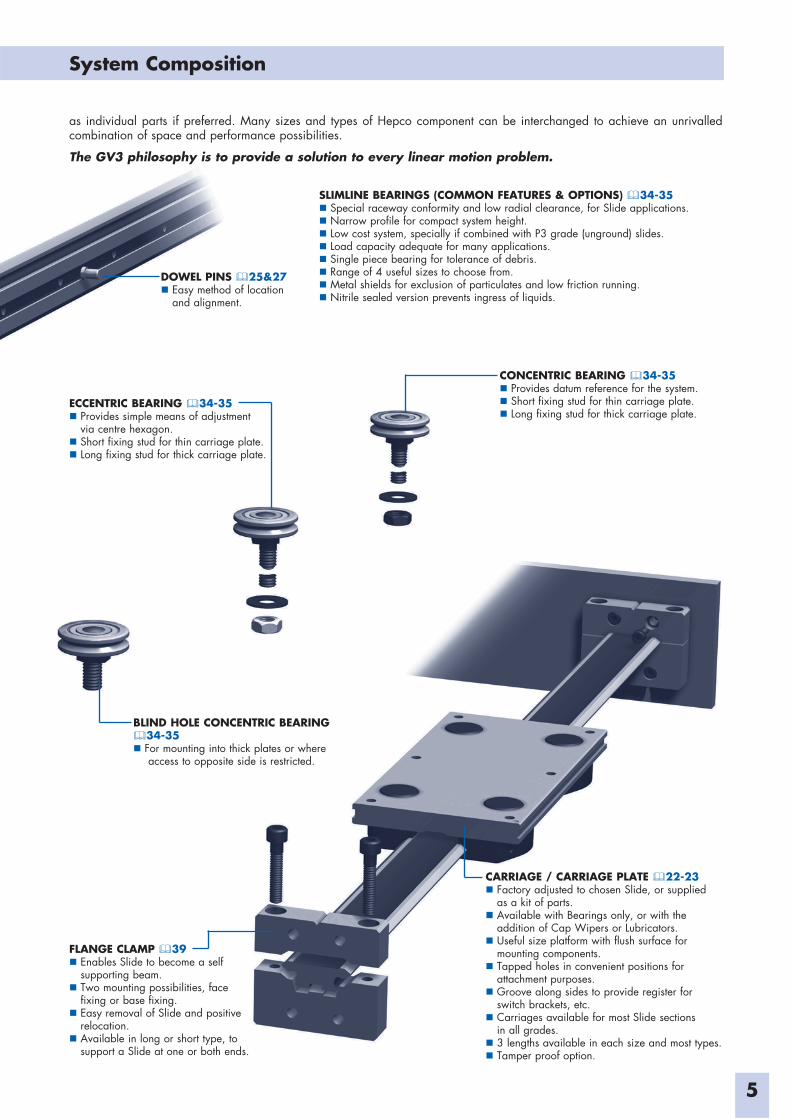
as individual parts if preferred. Many sizes and types of Hepco component can be interchanged to achieve an unrivalled combination of space and performance possibilities.
The GV3 philosophy is to provide a solution to every linear motion problem.
CARRIAGE / CARRIAGE PLATE 22-23Factory adjusted to chosen Slide, or supplied
as a kit of parts.Available with Bearings only, or with the
addition of Cap Wipers or Lubricators.Useful size platform with flush surface for
mounting components.Tapped holes in convenient positions for
attachment purposes.Groove along sides to provide register for
switch brackets, etc.Carriages available for most Slide sections
in all grades. 3 lengths available in each size and most types.Tamper proof option.
DOWEL PINS 25&27Easy method of location
and alignment.
SLIMLINE BEARINGS (COMMON FEATURES & OPTIONS) 34-35Special raceway conformity and low radial clearance, for Slide applications.Narrow profile for compact system height.Low cost system, specially if combined with P3 grade (unground) slides.Load capacity adequate for many applications. Single piece bearing for tolerance of debris. Range of 4 useful sizes to choose from. Metal shields for exclusion of particulates and low friction running.Nitrile sealed version prevents ingress of liquids.
CONCENTRIC BEARING 34-35Provides datum reference for the system.Short fixing stud for thin carriage plate.Long fixing stud for thick carriage plate.
ECCENTRIC BEARING 34-35Provides simple means of adjustment
via centre hexagon.Short fixing stud for thin carriage plate.Long fixing stud for thick carriage plate.
BLIND HOLE CONCENTRIC BEARING34-35For mounting into thick plates or where
access to opposite side is restricted.
FLANGE CLAMP 39Enables Slide to become a self
supporting beam.Two mounting possibilities, face
fixing or base fixing.Easy removal of Slide and positive
relocation.Available in long or short type, to
support a Slide at one or both ends.
System Composition
6
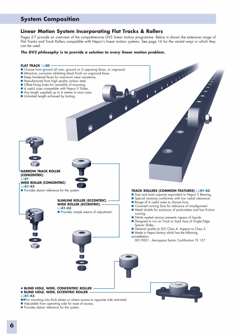
Linear Motion System Incorporating Flat Tracks & RollersPages 2-7 provide an overview of the comprehensive GV3 linear motion programme. Below is shown the extensive range of Flat Tracks and Track Rollers compatible with Hepco’s linear motion systems. See page 16 for the varied ways in which they can be used.
The GV3 philosophy is to provide a solution to every linear motion problem.
TRACK ROLLERS (COMMON FEATURES) 41-43Size and load capacity equivalent to Hepco V Bearing.Special raceway conformity with low radial clearance.Range of 4 useful sizes to choose from.Crowned running face for tolerance of misalignment.Metal shields for exclusion of particulates and low friction
running.Nitrile sealed version prevents ingress of liquids.Designed to run on Track or back face of Single Edge
Spacer Slides.General quality to ISO Class 4. Aspects to Class 2.Made in Hepco factory which has the following
accreditation: ISO 9001 - Aerospace Sector Certification TS 157.
NARROW TRACK ROLLER (CONCENTRIC)
41WIDE ROLLER (CONCENTRIC)
41-43Provides datum reference for the system.
SLIMLINE ROLLER (ECCENTRIC)WIDE ROLLER (ECCENTRIC)
41-43Provides simple means of adjustment.
BLIND HOLE, WIDE, CONCENTRIC ROLLERBLIND HOLE, WIDE, ECCENTRIC ROLLER41-43For mounting into thick plates or where access to opposite side restricted.
Adjustable from operating side for ease of access. Provides datum reference for the system.
FLAT TRACK 40Choose from ground all over, ground on 2 opposing faces, or unground.Attractive, corrosion inhibiting black finish on unground faces.Deep hardened faces for maximum wear resistance.Manufactured from high quality carbon steel.Offset fixing holes for versatility of mounting.4 useful sizes compatible with Hepco V Slides.Any length supplied up to 4 metres in most sizes.Unlimited length achieved by butting.
System Composition
7
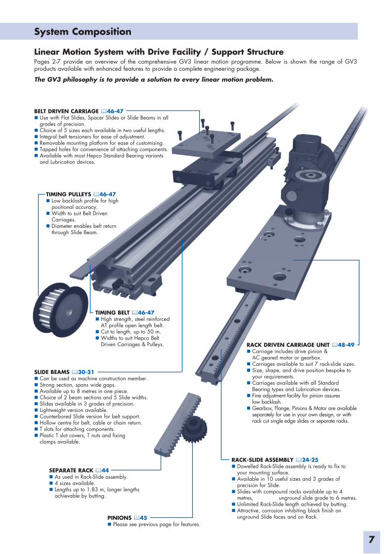
SLIDE BEAMS 30-31Can be used as machine construction member.Strong section, spans wide gaps.Available up to 8 metres in one piece. Choice of 2 beam sections and 5 Slide widths.Slides available in 3 grades of precision.Lightweight version available.Counterbored Slide version for belt support.Hollow centre for belt, cable or chain return.T slots for attaching components. Plastic T slot covers, T nuts and fixing
clamps available.
Linear Motion System with Drive Facility / Support StructurePages 2-7 provide an overview of the comprehensive GV3 linear motion programme. Below is shown the range of GV3 products available with enhanced features to provide a complete engineering package.
The GV3 philosophy is to provide a solution to every linear motion problem.
RACK DRIVEN CARRIAGE UNIT 48-49Carriage includes drive pinion &
AC geared motor or gearbox.Carriages available to suit 7 rack-slide sizes.Size, shape, and drive position bespoke to
your requirements.Carriages available with all Standard
Bearing types and Lubrication devices.Fine adjustment facility for pinion assures
low backlash.Gearbox, Flange, Pinions & Motor are available
separately for use in your own design, or with rack cut single edge slides or separate racks.
BELT DRIVEN CARRIAGE 46-47Use with Flat Slides, Spacer Slides or Slide Beams in all
grades of precision.Choice of 5 sizes each available in two useful lengths.Integral belt tensioners for ease of adjustment.Removable mounting platform for ease of customising.Tapped holes for convenience of attaching components.Available with most Hepco Standard Bearing variants
and Lubrication devices.
TIMING PULLEYS 46-47Low backlash profile for high
positional accuracy.Width to suit Belt Driven
Carriages.Diameter enables belt return
through Slide Beam.
TIMING BELT 46-47High strength, steel reinforced
AT profile open length belt.Cut to length, up to 50 m.Widths to suit Hepco Belt
Driven Carriages & Pulleys.
RACK-SLIDE ASSEMBLY 24-25Dowelled Rack-Slide assembly is ready to fix to
your mounting surface.Available in 10 useful sizes and 3 grades of
precision for Slide.Slides with compound racks available up to 4
metres, unground slide grade to 6 metres.Unlimited Rack-Slide length achieved by butting.Attractive, corrosion inhibiting black finish on
unground Slide faces and on Rack.PINIONS 45Please see previous page for features.
SEPARATE RACK 44As used in Rack-Slide assembly.4 sizes available.Lengths up to 1.83 m, longer lengths
achievable by butting.
Application Examples
8
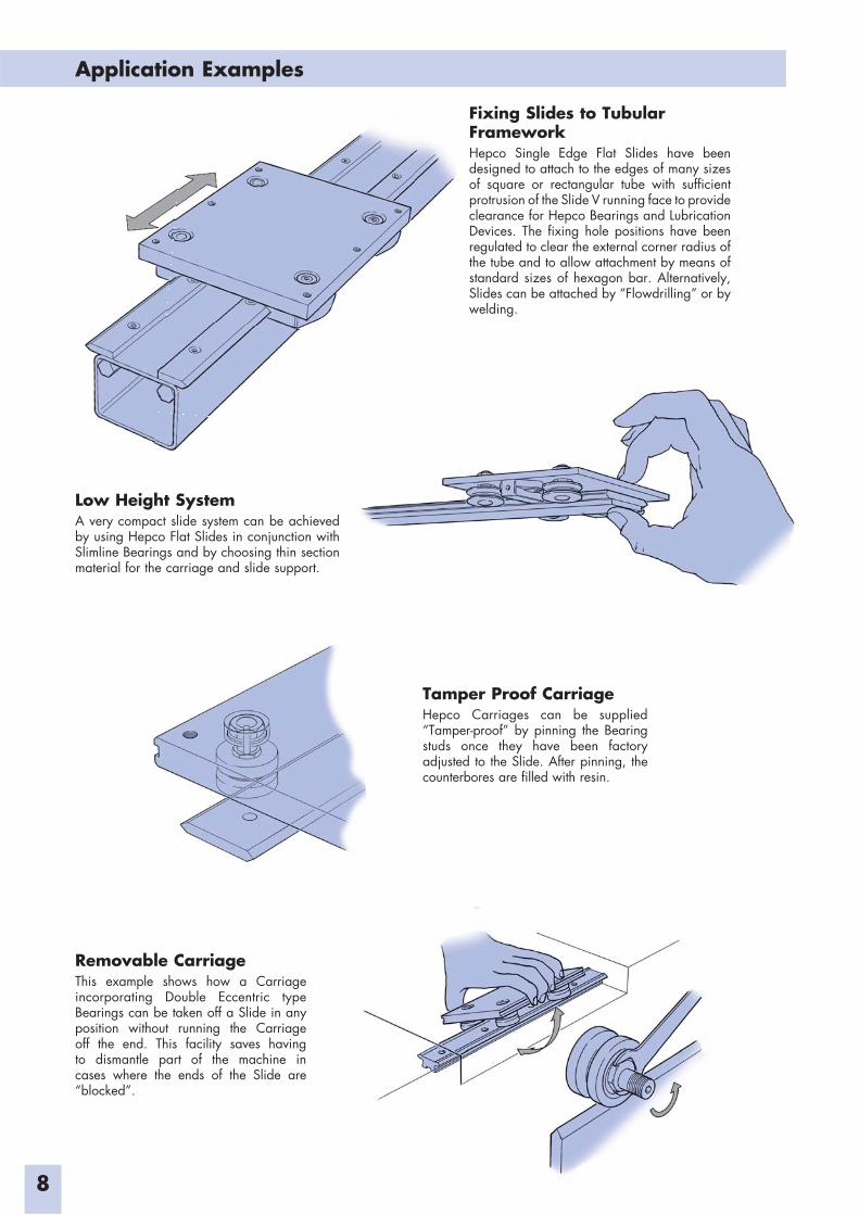
Fixing Slides to Tubular FrameworkHepco Single Edge Flat Slides have been designed to attach to the edges of many sizes of square or rectangular tube with sufficient protrusion of the Slide V running face to provide clearance for Hepco Bearings and Lubrication Devices. The fixing hole positions have been regulated to clear the external corner radius of the tube and to allow attachment by means of standard sizes of hexagon bar. Alternatively, Slides can be attached by “Flowdrilling” or by welding.
Low Height SystemA very compact slide system can be achieved by using Hepco Flat Slides in conjunction with Slimline Bearings and by choosing thin section material for the carriage and slide support.
Removable CarriageThis example shows how a Carriage incorporating Double Eccentric type Bearings can be taken off a Slide in any position without running the Carriage off the end. This facility saves having to dismantle part of the machine in cases where the ends of the Slide are “blocked”.
Tamper Proof CarriageHepco Carriages can be supplied “Tamper-proof” by pinning the Bearing studs once they have been factory adjusted to the Slide. After pinning, the counterbores are filled with resin.
Application Examples
9
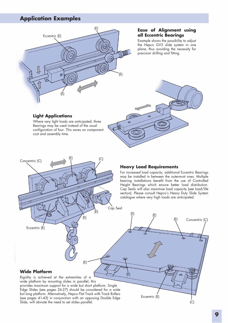
Ease of Alignment using all Eccentric BearingsExample shows the possibility to adjust the Hepco GV3 slide system in one plane, thus avoiding the necessity for precision drilling and fitting.
Light ApplicationsWhere very light loads are anticipated, three Bearings may be used instead of the usual configuration of four. This saves on component cost and assembly time.
Heavy Load RequirementsFor increased load capacity, additional Eccentric Bearings may be installed in between the outermost ones. Multiple bearing installations benefit from the use of Controlled Height Bearings which ensure better load distribution. Cap Seals will also maximise load capacity (see load/life section). Please consult Hepco’s Heavy Duty Slide System catalogue where very high loads are anticipated.
Wide Platform Rigidity is achieved at the extremities of a wide platform by mounting slides in parallel; this provides maximum support for a wide but short platform. Single Edge Slides (see pages 26-27) should be considered for a wide but long platform. Alternatively, Hepco Flat Track with Track Rollers (see pages 41-43) in conjunction with an opposing Double Edge Slide, will obviate the need to set slides parallel.
Eccentric (E)
(E)
(E)
(E)
Concentric (C) (C)(E)
Eccentric (E)
(E)
(E)
Cap Seal(E) (E)
(E)
(E)
(E) Concentric (C)
Eccentric (E)(C)
Application Examples
10
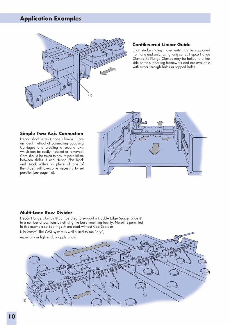
Simple Two Axis ConnectionHepco short series Flange Clamps are an ideal method of connecting opposing Carriages and creating a second axis which can be easily installed or removed. Care should be taken to ensure parallelism between slides. Using Hepco Flat Track and Track rollers in place of one of the slides will overcome necessity to set parallel (see page 16).
Cantilevered Linear GuideShort stroke sliding movements may be supported from one end only, using long series Hepco Flange Clamps . Flange Clamps may be bolted to either side of the supporting framework and are available with either through holes or tapped holes.
Multi-Lane Row DividerHepco Flange Clamps can be used to support a Double Edge Spacer Slide in a number of positions by utilising the base mounting facility. No oil is permitted in this example so Bearings are used without Cap Seals orLubricators. The GV3 system is well suited to run “dry”,especially in lighter duty applications.
Application Examples
11
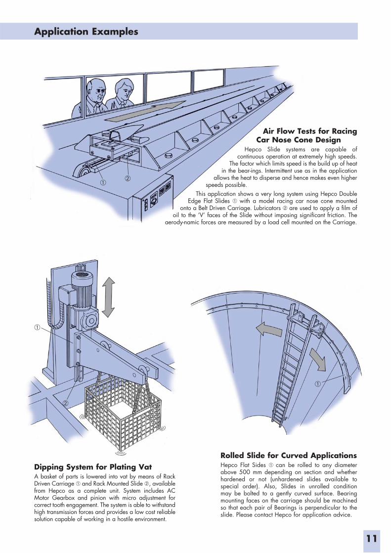
Dipping System for Plating VatA basket of parts is lowered into vat by means of Rack Driven Carriage and Rack Mounted Slide , available from Hepco as a complete unit. System includes AC Motor Gearbox and pinion with micro adjustment for correct tooth engagement. The system is able to withstand high transmission forces and provides a low cost reliable solution capable of working in a hostile environment.
Rolled Slide for Curved ApplicationsHepco Flat Sides can be rolled to any diameter above 500 mm depending on section and whether hardened or not (unhardened slides available to special order). Also, Slides in unrolled condition may be bolted to a gently curved surface. Bearing mounting faces on the carriage should be machined so that each pair of Bearings is perpendicular to the slide. Please contact Hepco for application advice.
Air Flow Tests for Racing Car Nose Cone Design
Hepco Slide systems are capable of continuous operation at extremely high speeds.
The factor which limits speed is the build up of heat in the bear-ings. Intermittent use as in the application
allows the heat to disperse and hence makes even higher speeds possible.
This application shows a very long system using Hepco Double Edge Flat Slides with a model racing car nose cone mounted
onto a Belt Driven Carriage. Lubricators are used to apply a film of oil to the ‘V’ faces of the Slide without imposing significant friction. The
aerody-namic forces are measured by a load cell mounted on the Carriage.
Application Examples
12
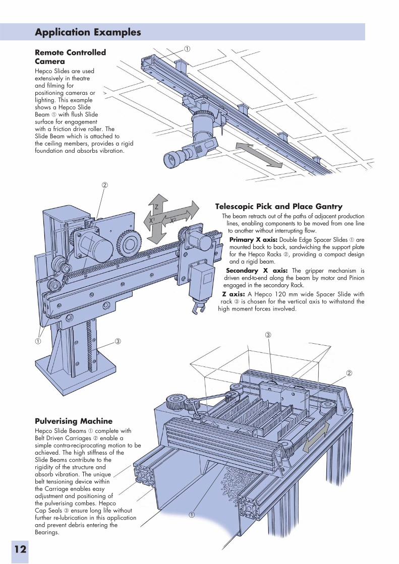
Remote Controlled CameraHepco Slides are used extensively in theatre and filming for positioning cameras or lighting. This example shows a Hepco Slide Beam with flush Slide surface for engagement with a friction drive roller. The Slide Beam which is attached to the ceiling members, provides a rigid foundation and absorbs vibration.
Pulverising MachineHepco Slide Beams complete with Belt Driven Carriages enable a simple contra-reciprocating motion to be achieved. The high stiffness of the Slide Beams contribute to the rigidity of the structure and absorb vibration. The unique belt tensioning device within the Carriage enables easy adjustment and positioning of the pulverising combes. Hepco Cap Seals ensure long life without further re-lubrication in this application and prevent debris entering the Bearings.
Telescopic Pick and Place GantryThe beam retracts out of the paths of adjacent production
lines, enabling components to be moved from one line to another without interrupting flow.Primary X axis: Double Edge Spacer Slides are mounted back to back, sandwiching the support plate for the Hepco Racks , providing a compact design and a rigid beam.
Secondary X axis: The gripper mechanism is driven end-to-end along the beam by motor and Pinion engaged in the secondary Rack.Z axis: A Hepco 120 mm wide Spacer Slide with rack is chosen for the vertical axis to withstand the
high moment forces involved.
Z
X1 X2
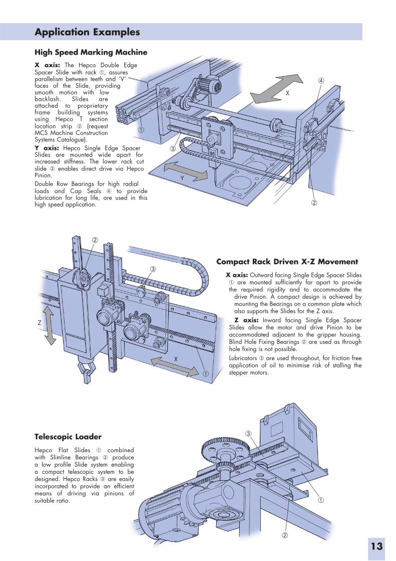
Telescopic Loader
Hepco Flat Slides combined with Slimline Bearings produce a low profile Slide system enabling a compact telescopic system to be designed. Hepco Racks are easily incorporated to provide an efficient means of driving via pinions of suitable ratio.
Compact Rack Driven X-Z Movement
X axis: Outward facing Single Edge Spacer Slides are mounted sufficiently far apart to provide
the required rigidity and to accommodate the drive Pinion. A compact design is achieved by mounting the Bearings on a common plate which also supports the Slides for the Z axis. Z axis: Inward facing Single Edge Spacer
Slides allow the motor and drive Pinion to be accommodated adjacent to the gripper housing. Blind Hole Fixing Bearings are used as through hole fixing is not possible.Lubricators are used throughout, for friction free application of oil to minimise risk of stalling the stepper motors.
Application Examples
13
High Speed Marking Machine
X axis: The Hepco Double Edge Spacer Slide with rack , assures parallelism between teeth and ‘V’ faces of the Slide, providing smooth motion with low backlash. Slides are attached to proprietary frame building systems using Hepco T section location strip (request MCS Machine Construction Systems Catalogue).Y axis: Hepco Single Edge Spacer Slides are mounted wide apart for increased stiffness. The lower rack cut slide enables direct drive via Hepco Pinion.Double Row Bearings for high radial loads and Cap Seals to provide lubrication for long life, are used in this high speed application.
gX
Y
X
Z
14
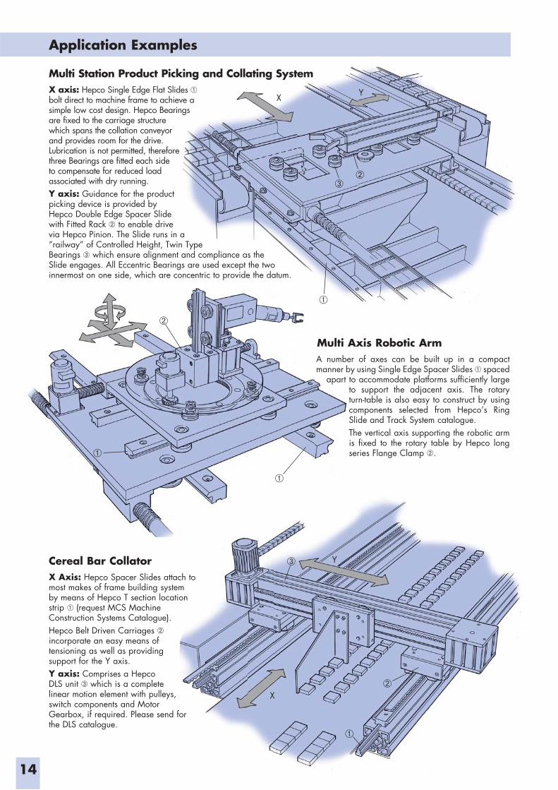
Multi Station Product Picking and Collating SystemX axis: Hepco Single Edge Flat Slides bolt direct to machine frame to achieve a simple low cost design. Hepco Bearings are fixed to the carriage structure which spans the collation conveyor and provides room for the drive. Lubrication is not permitted, therefore three Bearings are fitted each side to compensate for reduced load associated with dry running. Y axis: Guidance for the product picking device is provided by Hepco Double Edge Spacer Slide with Fitted Rack to enable drive via Hepco Pinion. The Slide runs in a “railway” of Controlled Height, Twin Type Bearings which ensure alignment and compliance as the Slide engages. All Eccentric Bearings are used except the two innermost on one side, which are concentric to provide the datum.
Cereal Bar CollatorX Axis: Hepco Spacer Slides attach to most makes of frame building system by means of Hepco T section location strip (request MCS Machine Construction Systems Catalogue). Hepco Belt Driven Carriages incorporate an easy means of tensioning as well as providing support for the Y axis.Y axis: Comprises a Hepco DLS unit which is a complete linear motion element with pulleys, switch components and Motor Gearbox, if required. Please send for the DLS catalogue.
Multi Axis Robotic ArmA number of axes can be built up in a compact manner by using Single Edge Spacer Slides spaced
apart to accommodate platforms sufficiently large to support the adjacent axis. The rotary turn-table is also easy to construct by using components selected from Hepco’s Ring Slide and Track System catalogue. The vertical axis supporting the robotic arm is fixed to the rotary table by Hepco long series Flange Clamp .
X
Y
Application Examples
YX
Application Examples
15
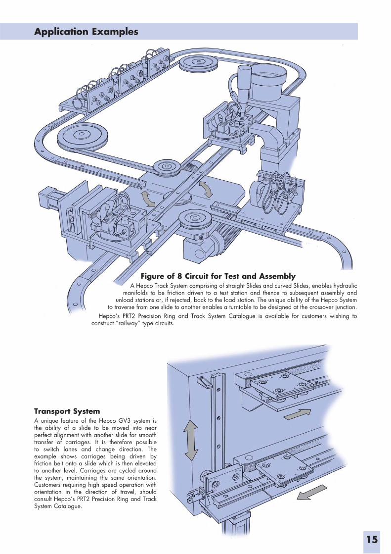
Transport SystemA unique feature of the Hepco GV3 system is the ability of a slide to be moved into near perfect alignment with another slide for smooth transfer of carriages. It is therefore possible to switch lanes and change direction. The example shows carriages being driven by friction belt onto a slide which is then elevated to another level. Carriages are cycled around the system, maintaining the same orientation. Customers requiring high speed operation with orientation in the direction of travel, should consult Hepco’s PRT2 Precision Ring and Track System Catalogue.
Figure of 8 Circuit for Test and AssemblyA Hepco Track System comprising of straight Slides and curved Slides, enables hydraulic
manifolds to be friction driven to a test station and thence to subsequent assembly and unload stations or, if rejected, back to the load station. The unique ability of the Hepco System
to traverse from one slide to another enables a turntable to be designed at the crossover junction.Hepco’s PRT2 Precision Ring and Track System Catalogue is available for customers wishing to
construct “railway” type circuits.
Application Examples
Slimline Bearings & Rollers Moving, Slide & Track Fixed
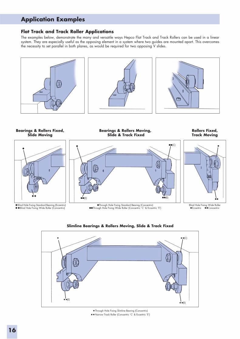
Flat Track and Track Roller ApplicationsThe examples below, demonstrate the many and versatile ways Hepco Flat Track and Track Rollers can be used in a linear system. They are especially useful as the opposing element in a system where two guides are mounted apart. This overcomes the necessity to set parallel in both planes, as would be required for two opposing V slides.
Through Hole Fixing Slimline Bearing (Concentric) Narrow Track Roller (Concentric ‘C’ & Eccentric ‘E’)
Blind Hole Fixing Standard Bearing (Eccentric)Blind Hole Fixing Wide Roller (Concentric)
Through Hole Fixing Standard Bearing (Concentric)Through Hole Fixing Wide Roller (Concentric ‘C’ & Eccentric ‘E’)
Blind Hole Fixing Wide RollerEccentric Concentric
Bearings & Rollers Moving, Slide & Track Fixed
Rollers Fixed,Track Moving
Bearings & Rollers Fixed,Slide Moving
(E)
(C)
(E)
(C)
(E)(E)
16
Lubrication Debris Safety & Lubrication Load Interval Exclusion Friction Appearance Price Method
Bearing Load Tolerance of System Tolerance of Type Speed Smoothness Misalignement Rigidity Height Debris Price
System Selector
17
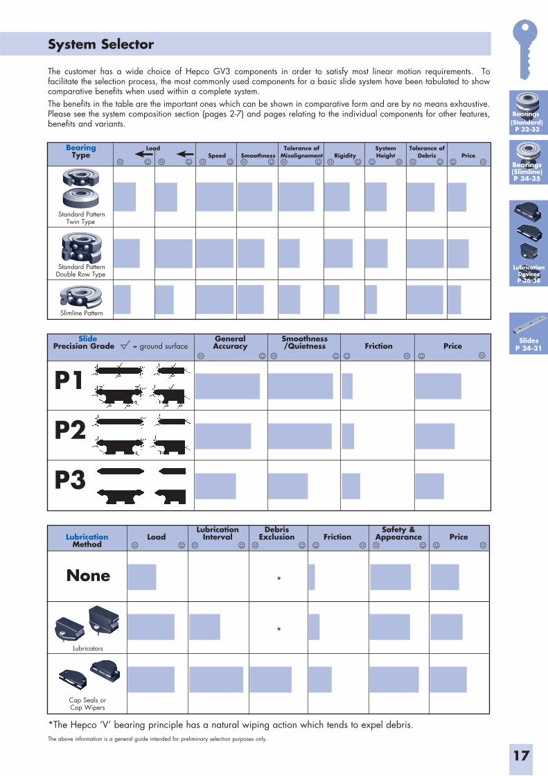
The customer has a wide choice of Hepco GV3 components in order to satisfy most linear motion requirements. To facilitate the selection process, the most commonly used components for a basic slide system have been tabulated to show comparative benefits when used within a complete system.The benefits in the table are the important ones which can be shown in comparative form and are by no means exhaustive. Please see the system composition section (pages 2-7) and pages relating to the individual components for other features, benefits and variants.
*The Hepco ‘V’ bearing principle has a natural wiping action which tends to expel debris.The above information is a general guide intended for preliminary selection purposes only.
Bearings(Standard)
P 32-33
Bearings(Slimline)P 34-35
Slide General Smoothness Precision Grade = ground surface Accuracy /Quietness Friction Price
P1
P2
P3
None
Lubricators
Cap Seals orCap Wipers
SlidesP 24-31
*
*
Standard Pattern Twin Type
Standard Pattern Double Row Type
Slimline Pattern
LubricationDevicesP 36-38
18
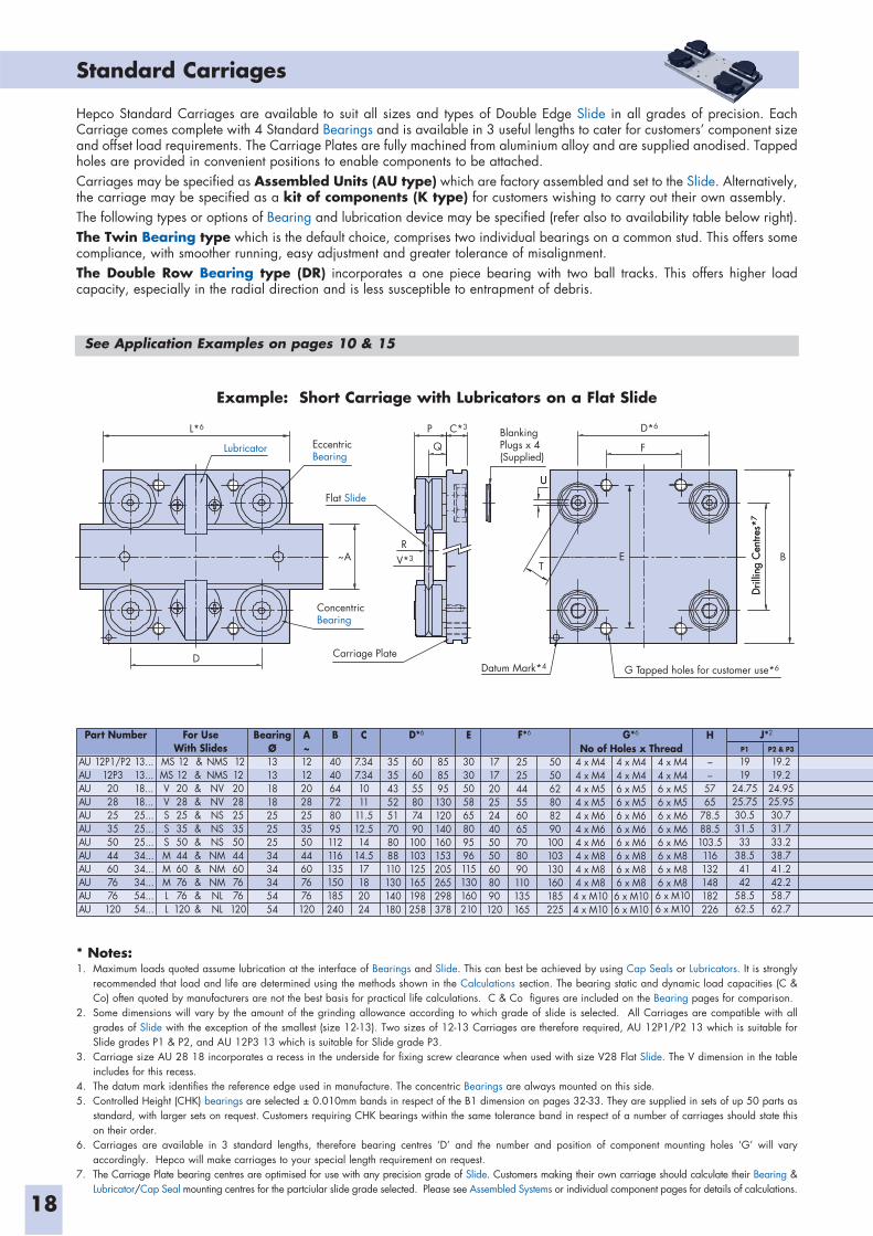
Standard Carriages
Example: Short Carriage with Lubricators on a Flat Slide
Hepco Standard Carriages are available to suit all sizes and types of Double Edge Slide in all grades of precision. Each Carriage comes complete with 4 Standard Bearings and is available in 3 useful lengths to cater for customers’ component size and offset load requirements. The Carriage Plates are fully machined from aluminium alloy and are supplied anodised. Tapped holes are provided in convenient positions to enable components to be attached.Carriages may be specified as Assembled Units (AU type) which are factory assembled and set to the Slide. Alternatively, the carriage may be specified as a kit of components (K type) for customers wishing to carry out their own assembly.The following types or options of Bearing and lubrication device may be specified (refer also to availability table below right).The Twin Bearing type which is the default choice, comprises two individual bearings on a common stud. This offers some compliance, with smoother running, easy adjustment and greater tolerance of misalignment.The Double Row Bearing type (DR) incorporates a one piece bearing with two ball tracks. This offers higher load capacity, especially in the radial direction and is less susceptible to entrapment of debris.
See Application Examples on pages 10 & 15
Dril
ling
Cen
tres*
7
T
U
E
U
F
B
D*6BlankingPlugs x 4(Supplied)
G Tapped holes for customer use*6 Datum Mark*4
C*3
V*3
L*6
R~A
D
ConcentricBearing
EccentricBearing
Flat Slide
Lubricator
Carriage Plate
P
Q
Dril
ling
Cen
tres*
7
Part Number For UseWith Slides
AUAUAUAUAUAUAUAUAUAUAUAU
MSMSVVSSSMMMLL
1212202825355044607676
120
&&&&&&&&&&&&
NMSNMSNVNVNSNSNSNMNMNMNLNL
1212202825355044607676
120
12P1/P212P3202825355044607676
120
13...13...18...18...25...25...25...34...34...34...54...54...
BearingØ131318182525253434345454
A~1212202825355044607676
120
B
404064728095112116135150185240
C
7.347.341011
11.512.514
14.517182024
E
3030505865809596115130160210
H
––
5765
78.588.5103.5116132148182226
3535435251708088110130140180
606055807490100103125165198258
858595130120140160153205265298378
1717202524405050608090120
252544556065708090110135165
505062808290100103130160185225
4 x M44 x M44 x M54 x M54 x M64 x M64 x M64 x M84 x M84 x M84 x M104 x M10
No of Holes x Thread4 x M44 x M46 x M56 x M56 x M66 x M66 x M66 x M86 x M86 x M86 x M106 x M10
4 x M44 x M46 x M56 x M56 x M66 x M66 x M66 x M86 x M86 x M86 x M106 x M10
D*6 F*6 G*6 J*2
P1
1919
24.7525.7530.531.533
38.54142
58.562.5
P2 & P3
19.219.2
24.9525.9530.731.733.238.741.242.258.762.7
* Notes:1. Maximum loads quoted assume lubrication at the interface of Bearings and Slide. This can best be achieved by using Cap Seals or Lubricators. It is strongly
recommended that load and life are determined using the methods shown in the Calculations section. The bearing static and dynamic load capacities (C & Co) often quoted by manufacturers are not the best basis for practical life calculations. C & Co figures are included on the Bearing pages for comparison.
2. Some dimensions will vary by the amount of the grinding allowance according to which grade of slide is selected. All Carriages are compatible with all grades of Slide with the exception of the smallest (size 12-13). Two sizes of 12-13 Carriages are therefore required, AU 12P1/P2 13 which is suitable for Slide grades P1 & P2, and AU 12P3 13 which is suitable for Slide grade P3.
3. Carriage size AU 28 18 incorporates a recess in the underside for fixing screw clearance when used with size V28 Flat Slide. The V dimension in the table includes for this recess.
4. The datum mark identifies the reference edge used in manufacture. The concentric Bearings are always mounted on this side.5. Controlled Height (CHK) bearings are selected ± 0.010mm bands in respect of the B1 dimension on pages 32-33. They are supplied in sets of up 50 parts as
standard, with larger sets on request. Customers requiring CHK bearings within the same tolerance band in respect of a number of carriages should state this on their order.
6. Carriages are available in 3 standard lengths, therefore bearing centres ‘D’ and the number and position of component mounting holes ‘G’ will vary accordingly. Hepco will make carriages to your special length requirement on request.
7. The Carriage Plate bearing centres are optimised for use with any precision grade of Slide. Customers making their own carriage should calculate their Bearing & Lubricator/Cap Seal mounting centres for the partciular slide grade selected. Please see Assembled Systems or individual component pages for details of calculations.
19
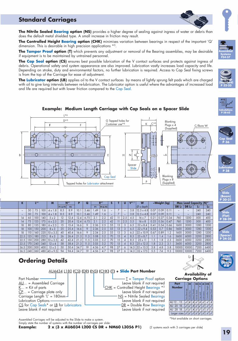
Assembled Carriages will be adjusted to the Slide to make a system. Simply state the number of systems with the number of carriages per slide:Example: 2 x (3 x AU6034 L200 CS DR + NM60 L3056 P1) (2 systems each with 3 carriages per slide)
T = Tamper Proof option Leave blank if not required
CHK = Controlled Height Bearings *5
Leave blank if not requiredNS = Nitrile Sealed Bearings
Leave blank if not requiredDR = Double Row BearingsLeave blank if not required
Part NumberAU... = Assembled Carriage K... = Kit of partsCP... = Carriage plate onlyCarriage Length ‘L’ = 180mmLubrication OptionsCS for Cap Seals* or LB for Lubricators Leave blank if not required
Standard Carriages
G Tapped holes forCustomer use*6
BlankingPlugs x 4(Supplied)
BlankingPlugs x 8(Supplied)Tapped holes for Lubricator attachment
SpacerSlide
Cap Seal
S
B
FFD*5
F
H
J
P
K
E ~A
C/Bore W
MN
L*6
C*3
Ordering Details
Example: Medium Length Carriage with Cap Seals on a Spacer Slide
The Nitrile Sealed Bearing option (NS) provides a higher degree of sealing against ingress of water or debris than does the default metal shielded type. A small increase in friction may result.The Controlled Height Bearing option (CHK) minimises variation between bearings in respect of the important ‘Q’ dimension. This is desirable in high precision applications *5.The Tamper Proof option (T) which prevents any adjustment or removal of the Bearing assemblies, may be desirable if equipment is to be maintained by untrained personnel.The Cap Seal option (CS) ensures best possible lubrication of the V contact surfaces and protects against ingress of debris. Operational safety and system appearance are also improved. Lubrication vastly increases load capacity and life. Depending on stroke, duty and environmental factors, no further lubrication is required. Access to Cap Seal fixing screws is from the top of the Carriage for ease of adjustment. The Lubricator option (LB) applies oil to the V contact surfaces by means of lightly sprung felt pads which are charged with oil to give long intervals between re-lubrication. The Lubricator option is useful where the advantages of increased load and life are required but with lower friction compared to the Cap Seal.
L1
L2
Availability of Carriage OptionsPart
Number
Larger sizes
–
12...2028
13...18...18...
DR CS
*LB CHK T– NS
AUAUAU
Twin
Bea
ring
s
Dou
ble
Row
Met
al S
hiel
ds
Nitr
ile S
eals
Cap
sea
ls
Lubr
icat
ors
Con
trol
led H
eight
Tam
per
Proo
f
*Not available on short carriages.
M
4 x 1.84 x 1.85 x 2
6 x 2.56 x 2.58 x 3
10 x 3.58 x 3
10 x 3.512 x 415 x 5
45 x 9.5
K
––
1414181818
22.522.522.536.536.5
S
––
42425555557070709898
U
––
2.52.533344466
0.070.070.210.250.410.530.671.11.51.83.85.5
0.090.090.270.360.540.70.891.41.82.34.87.4
0.110.110.340.470.660.861.21.62.33.15.89.3
T
7711111313131515152727
P
10.110.112.412.416.616.616.621.321.321.334.734.7
Q
5.465.466.756.75
999
11.511.511.51919
DR L1
––
760760
1600160016003600360036001000010000
DR L2
––
120012003000300030006000600060001000010000
L1
24024050050012801280128032003200320072007200
L2
24024040040012001200120028002800280064006400
WØ x depth12.5 x 4.812.5 x 4.8
16 x 716 x 8
22 x 8.422 x 9.422 x 10.925 x 8.725 x 11
25 x 12.532 x 13.532 x 17.5
V*2,3R*2 ~Weight (kg) Max Load Capacity (N)*1
5050657580100110125150170200240
7575100125135150160180200240300360
3.83.84.55.56.56.56.58.38.38.314.314.3
100100140175180200220225280340400480
N*2L*6
P1 & P2
8.58.512201525402642585094
P3
8.98.912.420.415.425.440.426.442.458.450.494.4
P1
1.491.492.12.1
2.362.362.343.083.053.054.564.56
P2 & P3
1.61.62.22.22.52.52.53.23.23.24.74.7
AU4434 L180 (CS) (DR) (NS) (CHK) (T) + Slide Part Number
AssembledSystemsP54-57
CalculationsP 58-62
XYZ+ABC
123
Cap SealP 36
LubricatorP 38
Tamper Proof
OptionP 8
Slide(Beam)P 30-31
Slide(Flat)
P 28-29
Bearings(Standard)P 32-33
Slide(Spacer)P 24-25
19a
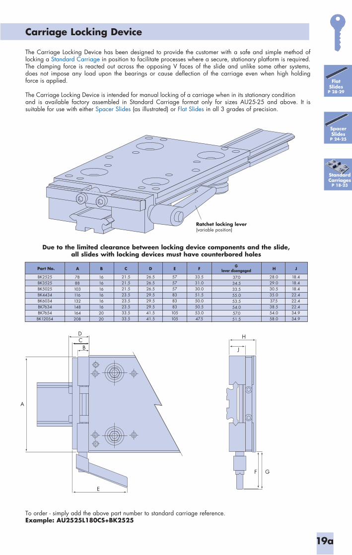
Carriage Locking Device
The Carriage Locking Device has been designed to provide the customer with a safe and simple method of locking a Standard Carriage in position to facilitate processes where a secure, stationary platform is required. The clamping force is reacted out across the opposing V faces of the slide and unlike some other systems, does not impose any load upon the bearings or cause deflection of the carriage even when high holding force is applied.
The Carriage Locking Device is intended for manual locking of a carriage when in its stationary condition and is available factory assembled in Standard Carriage format only for sizes AU25-25 and above. It is suitable for use with either Spacer Slides (as illustrated) or Flat Slides in all 3 grades of precision.
Standard Carriages
P 18-23
Flat SlidesP 28-29
SpacerSlidesP 24-25
To order - simply add the above part number to standard carriage reference.Example: AU2525L180CS+BK2525
Ratchet locking lever(variable position)
CD
B
A
E
H
J
F G
Due to the limited clearance between locking device components and the slide, all slides with locking devices must have counterbored holes
Glever disengaged
BK2525BK3525BK5025BK4434BK6034BK7634BK7654
BK12054
37.034.533.555.053.554.057.051.5
A
7888103116132148164208
B
1616161616162020
C
21.521.521.523.523.523.533.533.5
D
26.526.526.529.529.529.541.541.5
E
575757838383105105
F
33.531.030.051.550.050.553.047.5
J
18.418.418.422.422.422.434.934.9
H
28.029.030.535.037.538.554.058.0
Part No.
19b
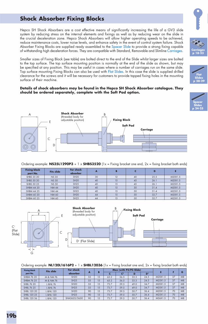
Shock Absorber Fixing Blocks
FlatSlides
p 28-29
Carriages p 18-23
Fixing blockpart No.
SHBS 35 20SHBS 50 20SHBS 50 25SHBM 44 20SHBM 44 25SHBM 60 20SHBM 60 25
NS 35NS 50NS 50NM 44NM 44NM 60NM 60
For shockabsorber
SH20SH20SH25SH20SH25SH20SH25
A B
30404040404444
12151515151515
C
40454550505050
D
25.526.126.131.431.432.732.7
E
M20X1.5M20X1.5M25X1.5M20X1.5M25X1.5M20X1.5M25X1.5
Fits slide
SHBM 76 20SHBM 76 25SHBL 76 20SHBL 76 25SHBL 120 20SHBL 120 25SHBL 120 36
M & NM 76M & NM 76
L &NL 76L &NL 76
L &NL 120L &NL 120L &NL 120
For shock absorber
SH20SH25SH20SH25SH20SH25
SHA3625/3650
Fits slide BA
55555555909090
15151515151515
C C1
65.265.273.773.773.773.773.7
56.556.559.559.559.559.559.5
D1
24.524.534.734.736.436.436.4
D33.333.349.049.050.750.750.7
37373737707070
E F
M8M8M8M8M8M8M8
G
M20X1.5M25X1.5M20X1.5M25X1.5M20X1.5M25X1.5M36X1.5
Max (with P2/P3 Slide)Fixing blockpart No.
Hepco SH Shock Absorbers are a cost effective means of significantly increasing the life of a GV3 slide system by reducing stress on the internal elements and fixings as well as by reducing wear on the slide in the crucial deceleration zone. Hepco Shock Absorbers will allow higher operating speeds to be achieved, reduce maintenance costs, lower noise levels, and enhance safety in the event of control system failure. Shock Absorber Fixing Blocks are supplied ready assembled to the Spacer Slide to provide a strong fixing capable of withstanding high deceleration forces. They are compatible with Standard, Removable and Slimline Carriages.
Smaller sizes of Fixing Block (see table) are bolted direct to the end of the Slide whilst larger sizes are bolted to the top surface. The top surface mounting position is normally at the end of the slide as shown, but may be specified at any position. This may be useful in cases where a number of carriages run on the same slide. Top surface mounting Fixing Blocks can also be used with Flat Slides. In this case the slide is supplied drilled clearance for the screws and it will be necessary for customers to provide tapped fixing holes in the mounting surface of their machine.
Details of shock absorbers may be found in the Hepco SH Shock Absorber catalogue. They should be ordered separately, complete with the Soft Pad option.
Ordering example: NS35L1290P3 + 1 x SHBS3520 (1x = Fixing bracket one end, 2x = fixing bracket both ends)
Ordering example: NL120L1616P2 + 1 x SHBL12036 (1x = Fixing bracket one end, 2x = fixing bracket both ends)
A
E
C
D
Shock Absorber(threaded body foradjustable position)
B
B
Fixing Block
Soft PadCarriage
AShock Absorber(threaded body foradjustable position)E
C
F
C1
(FlatSlide)
G
D D1 (Flat Slide)
Fixing Block
Soft PadCarriage
SpacerSlides
p 24-25
20
Removable Carriages
Example: Short Carriage with Lubricators on a Flat Slide
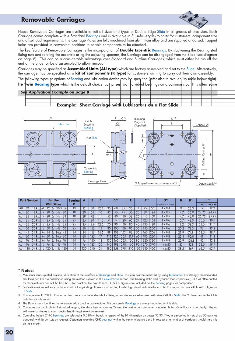
Hepco Removable Carriages are available to suit all sizes and types of Double Edge Slide in all grades of precision. Each Carriage comes complete with 4 Standard Bearings and is available in 3 useful lengths to cater for customers’ component size and offset load requirements. The Carriage Plates are fully machined from aluminium alloy and are supplied anodised. Tapped holes are provided in convenient positions to enable components to be attached.The key feature of Removable Carriages is the incorporation of Double Eccentric Bearings. By slackening the Bearing stud fixing nuts and rotating the eccentric using the adjusting spanner, the Carriage can be disengaged from the Slide (see diagram on page 8). This can be a considerable advantage over Standard and Slimline Carriages, which must either be run off the end of the Slide, or be disassembled to allow removal.Carriages may be specified as Assembled Units (AU type) which are factory assembled and set to the Slide. Alternatively, the carriage may be specified as a kit of components (K type) for customers wishing to carry out their own assembly.The following types or options of Bearing and lubrication device may be specified (refer also to availability table below right).he Twin Bearing type which is the default choice, comprises two individual bearings on a common stud. This offers some
See Application Example on page 8
For UseWith Slides
AUAUAUAUAUAUAUAUAUAUAU
MSVVSSSMMMLL
12202825355044607676
120
&&&&&&&&&&&
NMSNVNVNSNSNSNMNMNMNLNL
12202825355044607676
120
12202825355044607676
120
13 R...18 R...18 R...25 R...25 R...25 R...34 R...34 R...34 R...54 R...54 R...
BearingØ1318182525253434345454
A
12202825355044607676
120
Part Number B
4064728095112116135150185240
C
7.341011
11.512.514
14.517182024
E
30505865809596115130160210
H
914.714.716.719.220.221.923.422.933
38.5
H1
23.335.943.948.358.373.374.890.8106.8123167
35435251708088110130140180
6055807490100103125165198258
8595130120140160153205265298378
17202524405050608090120
2588110120130140160180220270330
50124160164180200206260320370450
No of Holes x Thread
4 x M44 x M54 x M54 x M64 x M64 x M64 x M84 x M84 x M84 x M104 x M10
D*5 F*5 G*5 J*2
P1
1924.7525.7530.531.533
38.54142
58.562.5
P2 & P3
19.224.9525.9530.731.733.238.741.242.258.762.7
BlankingPlugs x 4(Supplied)
G Tapped holes for customer use*5 Datum Mark*4
DoubleEccentricBearing
ConcentricBearing
Carriage Plate
C/Bore W
Dril
ling
Cen
tres
H1
Flat Slide
P
Q
U
T B
H
F
V*3
C*3 D*5 L*5
R
Lubricator
D
A E
* Notes:1. Maximum loads quoted assume lubrication at the interface of Bearings and Slide. This can best be achieved by using Lubricators. It is strongly recommended
that load and life are determined using the methods shown in the Calculations section. The bearing static and dynamic load capacities (C & Co) often quoted by manufacturers are not the best basis for practical life calculations. C & Co figures are included on the Bearing pages for comparison.
2. Some dimensions will vary by the amount of the grinding allowance according to which grade of slide is selected. All Carriages are compatible with all grades of Slide.
3. Carriage size AU 28 18 R incorporates a recess in the underside for fixing screw clearance when used with size V28 Flat Slide. The V dimension in the table includes for this recess.
4. The Datum mark identifies the reference edge used in manufacture. The concentric Bearings are always mounted on this side.5. Carriages are available in 3 standard lengths, therefore bearing centres ‘D’ and the position of component mounting holes ‘G’ will vary accordingly. Hepco
will make carriages to your special length requirement on request.6. Controlled height (CHK) bearings are selected ± 0.010mm bands in respect of the B1 dimension on pages 32-33. They are supplied in sets of up 50 parts as
standard, with larger sets on request. Customers requiring CHK bearings within the same tolerance band in respect of a number of carriages should state this on their order.
Part NumberAU... = Assembled Carriage K... = Kit of partsCP... = Carriage plate onlyCarriage Length ‘L’ = 180mmR = Removable Type Carriage
CHK = ControlledHeight Bearings *6
Leave blank if not requiredNS = Nitrile Sealed Bearings
Leave blank if not requiredDR = Double Row BearingsLeave blank if not required
Lubrication Option: LB for Lubricators Leave blank if not required
21
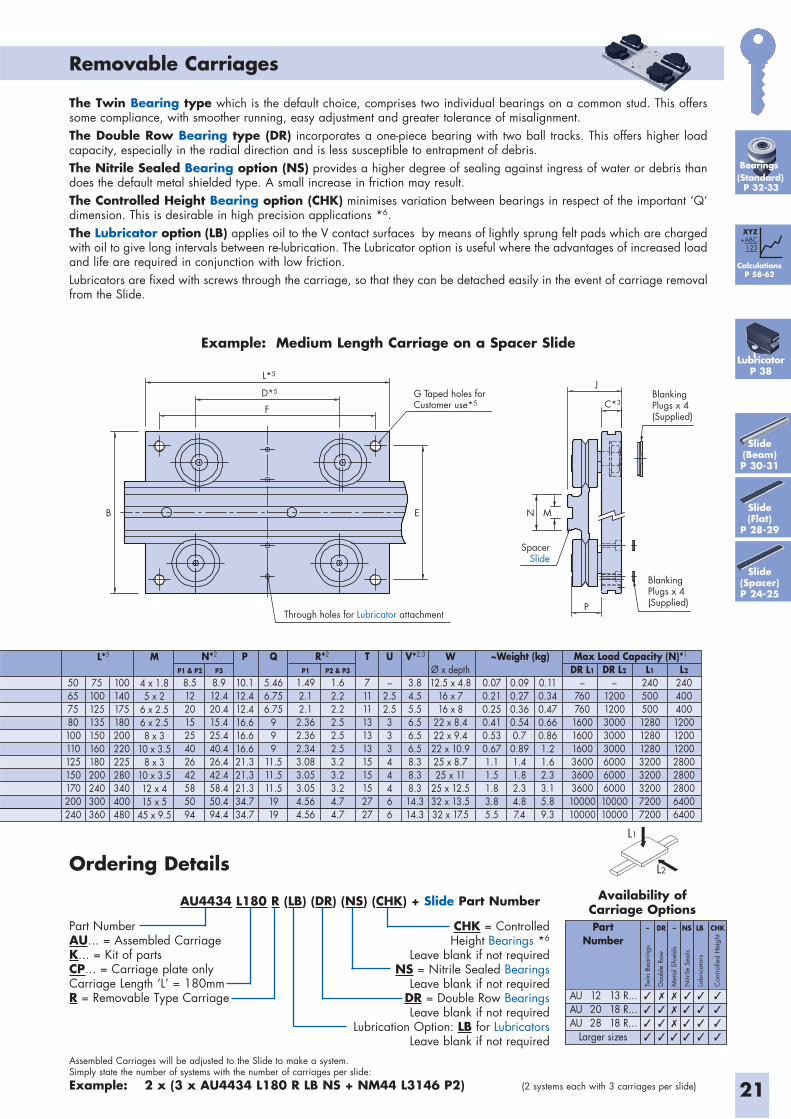
Assembled Carriages will be adjusted to the Slide to make a system. Simply state the number of systems with the number of carriages per slide:Example: 2 x (3 x AU4434 L180 R LB NS + NM44 L3146 P2) (2 systems each with 3 carriages per slide)
Removable Carriages
Ordering Details
AU4434 L180 R (LB) (DR) (NS) (CHK) + Slide Part Number
Example: Medium Length Carriage on a Spacer Slide
L1
L2
M
4 x 1.85 x 2
6 x 2.56 x 2.58 x 3
10 x 3.58 x 3
10 x 3.512 x 415 x 5
45 x 9.5
L*5 U
–2.52.533344466
0.070.210.250.410.530.671.11.51.83.85.5
0.090.270.360.540.70.891.41.82.34.87.4
0.110.340.470.660.861.21.62.33.15.89.3
T
711111313131515152727
3.84.55.56.56.56.58.38.38.314.314.3
P
10.112.412.416.616.616.621.321.321.334.734.7
Q
5.466.756.75
999
11.511.511.51919
DR L1
–760760
1600160016003600360036001000010000
DR L2
–120012003000300030006000600060001000010000
L1
24050050012801280128032003200320072007200
L2
24040040012001200120028002800280064006400
WØ x depth12.5 x 4.8
16 x 716 x 8
22 x 8.422 x 9.422 x 10.925 x 8.725 x 11
25 x 12.532 x 13.532 x 17.5
V*2,3R*2 ~Weight (kg) Max Load Capacity (N)*1
50657580100110125150170200240
75100125135150160180200240300360
100140175180200220225280340400480
N*2
P1 & P2
8.512201525402642585094
P3
8.912.420.415.425.440.426.442.458.450.494.4
P1
1.492.12.12.362.362.343.083.053.054.564.56
P2 & P3
1.62.22.22.52.52.53.23.23.24.74.7
Availability of Carriage OptionsPart
Number
Larger sizes
122028
13 R...18 R...18 R...
– NS LB CHKDR –
AUAUAU
Twin
Bea
ring
s
Dou
ble
Row
Met
al S
hiel
ds
Nitr
ile S
eals
Lubr
icat
ors
Con
trolle
d H
eigh
t
L*5
G Taped holes forCustomer use*5
D*5
F
E N
J
P
MB
Through holes for Lubricator attachment
C*3BlankingPlugs x 4(Supplied)
BlankingPlugs x 4 (Supplied)
SpacerSlide
Slide(Beam)P 30-31
Slide(Flat)
P 28-29
Slide(Spacer)P 24-25
CalculationsP 58-62
XYZ+ABC
123
LubricatorP 38
Bearings(Standard)
P 32-33
The Twin Bearing type which is the default choice, comprises two individual bearings on a common stud. This offers some compliance, with smoother running, easy adjustment and greater tolerance of misalignment.The Double Row Bearing type (DR) incorporates a one-piece bearing with two ball tracks. This offers higher load capacity, especially in the radial direction and is less susceptible to entrapment of debris.The Nitrile Sealed Bearing option (NS) provides a higher degree of sealing against ingress of water or debris than does the default metal shielded type. A small increase in friction may result.The Controlled Height Bearing option (CHK) minimises variation between bearings in respect of the important ‘Q’ dimension. This is desirable in high precision applications *6.The Lubricator option (LB) applies oil to the V contact surfaces by means of lightly sprung felt pads which are charged with oil to give long intervals between re-lubrication. The Lubricator option is useful where the advantages of increased load and life are required in conjunction with low friction.Lubricators are fixed with screws through the carriage, so that they can be detached easily in the event of carriage removal from the Slide.
22
Slimline Carriages
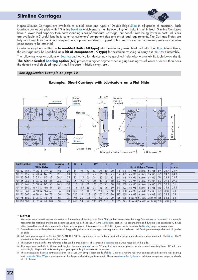
* Notes:1. Maximum loads quoted assume lubrication at the interface of Bearings and Slide. This can best be achieved by using Cap Wipers or Lubricators. It is strongly
recommended that load and life are determined using the methods shown in the Calculations section. The bearing static and dynamic load capacities (C & Co) often quoted by manufacturers are not the best basis for practical life calculations. C & Co figures are included on the Bearing pages for comparison.
2. Some dimensions will vary by the amount of the grinding allowance according to which grade of slide is selected. All Carriages are compatible with all grades of Slide.
3. All Carriages except sizes AU 76 580 & AU 120 580 incorporate a recess in the underside for fixing screw clearance when used with Flat Slides. The V dimension in the table includes for this recess.
4. The Datum mark identifies the reference edge used in manufacture. The concentric Bearings are always mounted on this side.5. Carriages are available in 3 standard lengths, therefore bearing centres ‘D’ and the number and position of component mounting holes ‘G’ will vary
accordingly. Hepco will make carriages to your special length requirement on request.6. The carriage plate bearing centres are optimised for use with any precision grade of slide. Customers making their own carriage should calculate their bearing
and Lubricator/Cap Wiper mounting centres for the partciular slide grade selected. Please see Assembled Systems or individual component pages for details of calculations.
Example: Short Carriage with Lubricators on a Flat Slide
Hepco Slimline Carriages are available to suit all sizes and types of Double Edge Slide in all grades of precision. Each Carriage comes complete with 4 Slimline Bearings which ensure that the overall system height is minimised. Slimline Carriages have a lower load capacity than corresponding sizes of Standard Carriage, but benefit from being lower in cost. All sizes are available in 3 useful lengths to cater for customers’ component size and offset load requirements. The Carriage Plates are fully machined from aluminium alloy and are supplied anodised. Tapped holes are provided in convenient positions to enable components to be attached.Carriages may be specified as Assembled Units (AU type) which are factory assembled and set to the Slide. Alternatively, the carriage may be specified as a kit of components (K type) for customers wishing to carry out their own assembly.The following types or options of Bearing and lubrication device may be specified (refer also to availability table below right).The Nitrile Sealed Bearing option (NS) provides a higher degree of sealing against ingress of water or debris than does the default metal shielded type. A small increase in friction may result.
See Application Example on page 10
Part Number For UseWith Slides
AUAUAUAUAUAUAUAUAUAU
VVSSSMMMLL
202825355044607676
120
&&&&&&&&&&
NVNVNSNSNSNMNMNMNLNL
202825355044607676
120
202825355044607676
120
195...195...265...265...265...360...360...360...580...580...
BearingØ
19.519.526.526.526.53636365858
A~202825355044607676
120
B
64728095112116135150195240
C
1011
11.512.514
14.517182024
E
505865809596115130170210
H
59677686101113129145186230
435255708085108128135185
5575749010098120160190240
90125120140160145200260290360
202525 405050608090120
44556065708090110135165
62808290100103130160185225
4 x M54 x M54 x M64 x M64 x M64 x M84 x M84 x M84 x M104 x M10
No of Holes x Thread6 x M56 x M56 x M66 x M66 x M66 x M86 x M86 x M86 x M106 x M10
6 x M56 x M56 x M66 x M66 x M66 x M86 x M86 x M86 x M106 x M10
D*5 F*5 G*5 J*2
P1
23.724.728.329.330.835.337.838.853.857.8
P2 & P3
23.924.928.529.531
35.538395458
U
TTE B
F
DL*5
D
V*3
C*3
R
P
Q
~A
Lubricator
Dril
ling
Cen
tres
H1*
6
DoubleEccentricBearing
ConcentricBearing
Carriage Plate
Flat Slide
BlankingPlugs x 4(Supplied)
Datum Mark*4G Tapped holes for customer use*5
T = Tamper Proof option Leave blank if not required
NS = Nitrile Sealed Bearings Leave blank if not required
Lubrication OptionsCW for Cap Wipers* or LB for Lubricators
Leave blank if not required
Part NumberAU... = Assembled Carriage K... = Kit of partsCP... = Carriage plate onlyCarriage Length ‘L’ = 180mm
23
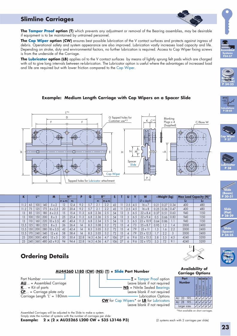
Assembled Carriages will be adjusted to the Slide to make a system. Simply state the number of systems with the number of carriages per slide:Example: 2 x (2 x AU35265 L200 CW + S35 L3146 P3) (2 systems each with 2 carriages per slide)
Slimline Carriages
Ordering Details
AU44360 L180 (CW) (NS) (T) + Slide Part Number
Example: Medium Length Carriage with Cap Wipers on a Spacer Slide
The Tamper Proof option (T) which prevents any adjustment or removal of the Bearing assemblies, may be desirable if equipment is to be maintained by untrained personnel.The Cap Wiper option (CW) ensures best possible lubrication of the V contact surfaces and protects against ingress of debris. Operational safety and system appearance are also improved. Lubrication vastly increases load capacity and life. Depending on stroke, duty and environmental factors, no further lubrication is required. Access to Cap Wiper fixing screws is from the underside of the Carriage. The Lubricator option (LB) applies oil to the V contact surfaces by means of lightly sprung felt pads which are charged with oil to give long intervals between re-lubrication. The Lubricator option is useful where the advantages of increased load and life are required but with lower friction compared to the Cap Wiper.
L1
L2
M
5 x 26 x 2.56 x 2.58 x 3
10 x 3.58 x 3
10 x 3.512 x 415 x 5
45 x 9.5
K
11.211.2131313
15.515.515.52525
S
4343545454727272106106
U
2.52.533344466
0.210.250.370.50.640.951.31.73.85.3
0.270.360.510.660.861.21.62.23.57.2
0.340.470.630.831.11.42.23
4.59.1
T
11111313131515152727
P
9.29.211.311.311.3141414
22.822.8
Q
5.75.76.86.86.88.38.38.314.314.3
L1
400400940940940
20002000200042404240
L2
48048011501150115024002400240052005200
WØ x depth
16 x 716 x 8
22 x 8.422 x 9.422 x 10.925 x 8.725 x 11
25 x 12.532 x 13.532 x 17.5
VR*2 ~Weight (kg) Max Load Capacity (N)*1
657585100110125150170200240
100125135150160180200240300360
4.54.56.56.56.57.37.97.99.69.6
140175180200220225280340400480
N*2L*5
P1 & P2
12201525402642585094
P3
12.420.415.425.440.426.442.458.450.494.4
P1
2.12.1
2.362.362.343.083.053.054.564.56
P2 & P3
2.22.22.52.52.53.23.23.24.74.7
Availability of Carriage Options
PartNumber
Larger sizes
2028
195...195...
– LB TNS CW
AUAU
Met
al S
hiel
ds
Nitr
ile S
eals
Cap W
iper
s
Lubrica
tors
Tam
per
Pro
or
*
BlankingPlugs x 4(Supplied)
Tapped holes for Lubricator attachment
SpacerSlide
Cap Wiper
S
B
F
D
F
H ~A
J
K
E
C/Bore W
M
P
N
L*5
C*3G Tapped holes forCustomer use*5
*Not available on short carriages.
CalculationsP 58-62
XYZ+ABC
123
Cap WiperP 37
LubricatorP 38
Tamper Proof
OptionP 8
Slide(Beam)P 30-31
Slide(Flat)
P 28-29
Slide(Spacer)P 24-25
AssembledSystemsP54-57
Bearings(Slimline)P 34-35
24
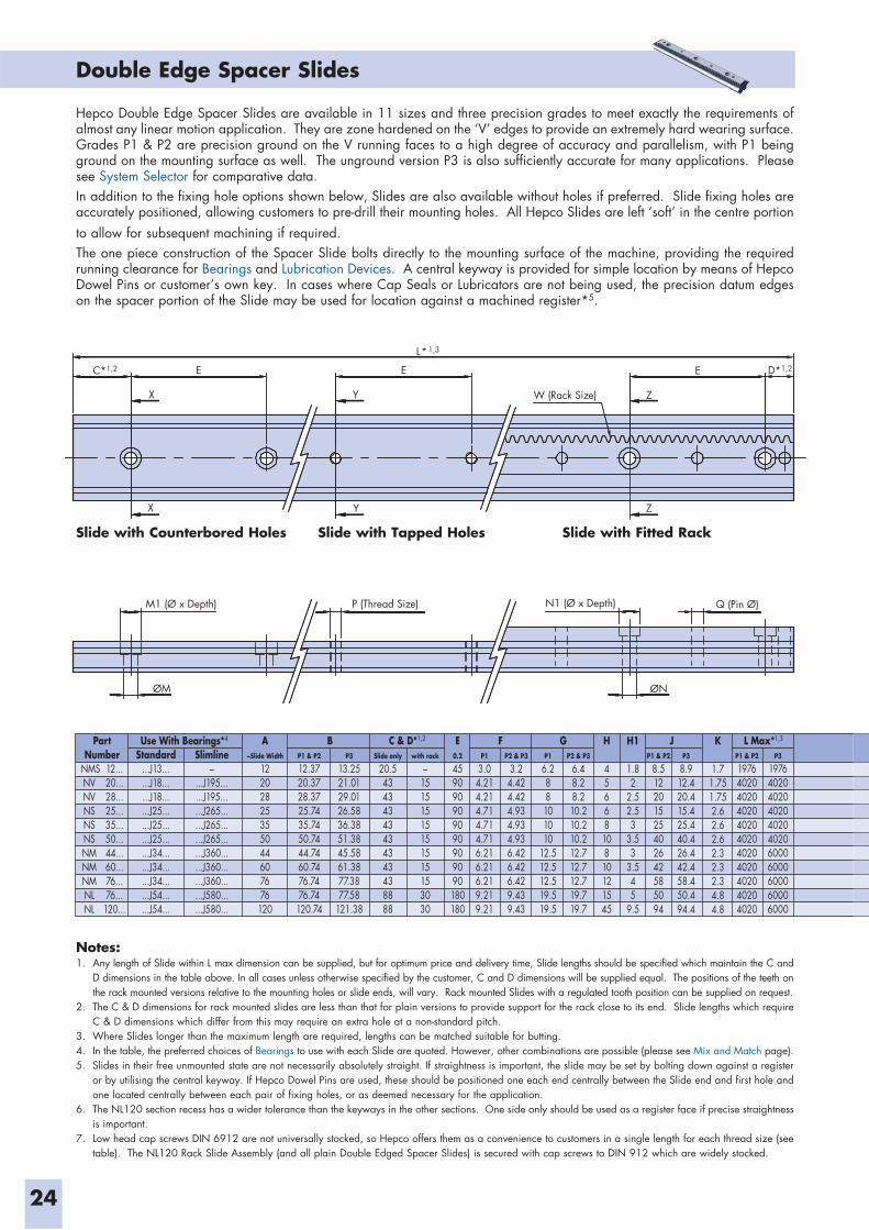
Double Edge Spacer Slides
Notes:1. Any length of Slide within L max dimension can be supplied, but for optimum price and delivery time, Slide lengths should be specified which maintain the C and
D dimensions in the table above. In all cases unless otherwise specified by the customer, C and D dimensions will be supplied equal. The positions of the teeth on the rack mounted versions relative to the mounting holes or slide ends, will vary. Rack mounted Slides with a regulated tooth position can be supplied on request.
2. The C & D dimensions for rack mounted slides are less than that for plain versions to provide support for the rack close to its end. Slide lengths which require C & D dimensions which differ from this may require an extra hole at a non-standard pitch.
3. Where Slides longer than the maximum length are required, lengths can be matched suitable for butting. 4. In the table, the preferred choices of Bearings to use with each Slide are quoted. However, other combinations are possible (please see Mix and Match page).5. Slides in their free unmounted state are not necessarily absolutely straight. If straightness is important, the slide may be set by bolting down against a register
or by utilising the central keyway. If Hepco Dowel Pins are used, these should be positioned one each end centrally between the Slide end and first hole and one located centrally between each pair of fixing holes, or as deemed necessary for the application.
6. The NL120 section recess has a wider tolerance than the keyways in the other sections. One side only should be used as a register face if precise straightness is important.
7. Low head cap screws DIN 6912 are not universally stocked, so Hepco offers them as a convenience to customers in a single length for each thread size (see table). The NL120 Rack Slide Assembly (and all plain Double Edged Spacer Slides) is secured with cap screws to DIN 912 which are widely stocked.
ØN
YX
X
E E E
ZW (Rack Size)Y
C*1,2
L*1,3
D*1,2
ØM
Z
Q (Pin Ø)N1 (Ø x Depth)M1 (Ø x Depth) P (Thread Size)
Slide with Counterbored Holes Slide with Fitted Rack
Hepco Double Edge Spacer Slides are available in 11 sizes and three precision grades to meet exactly the requirements of almost any linear motion application. They are zone hardened on the ‘V’ edges to provide an extremely hard wearing surface. Grades P1 & P2 are precision ground on the V running faces to a high degree of accuracy and parallelism, with P1 being ground on the mounting surface as well. The unground version P3 is also sufficiently accurate for many applications. Please see System Selector for comparative data.In addition to the fixing hole options shown below, Slides are also available without holes if preferred. Slide fixing holes are accurately positioned, allowing customers to pre-drill their mounting holes. All Hepco Slides are left ‘soft’ in the centre portion to allow for subsequent machining if required. The one piece construction of the Spacer Slide bolts directly to the mounting surface of the machine, providing the required running clearance for Bearings and Lubrication Devices. A central keyway is provided for simple location by means of Hepco Dowel Pins or customer’s own key. In cases where Cap Seals or Lubricators are not being used, the precision datum edges on the spacer portion of the Slide may be used for location against a machined register*5.
Slide with Tapped Holes
PartNumber
NMSNVNVNSNSNSNMNMNMNLNL
12...20...28...25...35...50...44...60...76...76...
120...
Use With Bearings*4
Standard...J13......J18......J18......J25......J25......J25......J34......J34......J34......J54......J54...
Slimline–
...J195...
...J195...
...J265...
...J265...
...J265...
...J360...
...J360...
...J360...
...J580...
...J580...
A~Slide Width
12202825355044607676
120
E0.2
459090909090909090180180
H
4566810810121545
K
1.71.751.752.62.62.62.32.32.34.84.8
H1
1.82
2.52.53
3.53
3.545
9.5
B C & D*1,2 L Max*1,3F G JP1 & P2
12.3720.3728.3725.7435.7450.7444.7460.7476.7476.74
120.74
P1
3.04.214.214.714.714.716.216.216.219.219.21
P2 & P3
3.24.424.424.934.934.936.426.426.429.439.43
P2 & P3
6.48.28.210.210.210.212.712.712.719.719.7
P3
8.912.420.415.425.440.426.442.458.450.494.4
P1 & P2
19764020402040204020402040204020402040204020
P3
19764020402040204020402060006000600060006000
Slide only
20.543434343434343438888
with rack
–15151515151515153030
P3
13.2521.0129.0126.5836.3851.3845.5861.3877.3877.58
121.38
P1
6.288101010
12.512.512.519.519.5
P1 & P2
8.512201525402642585094
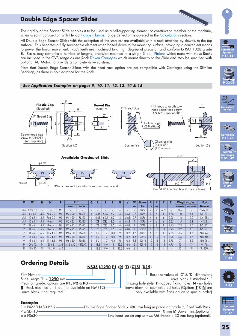
NS35 L1290 P1 (R) (T) (C15) (D15)
25
Double Edge Spacer Slides
Ordering Details
Part NumberSlide Length ‘L’ = 1290 mmPrecision grade: options are P1, P2 & P3R - Rack mounted on Slide (not available on NMS12)Leave blank if not required
Bespoke values of ‘C’ & ‘D’ dimensionsLeave blank if standard*1,2
Fixing hole style: T - tapped fixing holes; N - no holes leave blank for counterbored holes (Options T & N are
only available with Rack option to special order)
P3P2P1
G±0.025 J±0.013
B±0.013
Z
Z1
Y
XS
R
V
T
H1
V
U
Datum Edge(2 Positions)
P1 Thread x length Lowhead socket cap screwDIN 6912 (optional)*7
Chamfer min0.4 x 45°(4 Positions)
Dowel Pin(SDP) *5
Section X-X
B A
F
‘P’ Thread Size
H1
H
P Thread Size
J
GK
Plastic Cap(Supplied)
Socket head capscrew to DIN912
(not supplied)Section Y-Y Section Z-Z
Indicates surfaces which are precision groundThe NL120 Section has 2 rows of holes
+0.05–0
70±0.1
H+0.1*6 –0
The rigidity of the Spacer Slide enables it to be used as a self-supporting element or construction member of the machine, when used in conjunction with Hepco Flange Clamps. Slide deflection is covered in the Calculations section.All Double Edge Spacer Slides with the exception of the smallest are available with a rack attached by dowels to the top surface. This becomes a fully serviceable element when bolted down to the mounting surface, providing a convenient means to power the linear movement. Rack teeth are machined to a high degree of precision and conform to ISO 1328 grade 8. Racks may comprise a number of lengths, precision mounted to a single Slide. Pinions which mate with these Racks are included in the GV3 range as are Rack Driven Carriages which mount directly to the Slide and may be specified with optional AC Motor, to provide a complete drive solution.Note that Double Edge Spacer Slides with the fitted rack option are not compatible with Carriages using the Slimline Bearings, as there is no clearance for the Rack.
See Application Examples on pages 9, 10, 11, 12, 13, 14 & 15
Available Grades of Slide
Mix &Match
OptionsP 54
FlangeClampsP 39
PinionsP 45
M
3.54.55.55.5777991411
M1
6.2 x 3.18 x 4.110 x 5.110 x 5.111 x 6.111 x 6.111 x 6.115 x 8.115 x 8.120 x 1218 x 10
N
–4.54.55.55.55.56.56.56.51411
N1
–7.6 x 2.97.6 x 2.99.6 x 49.6 x 49.6 x 411 x 4.511 x 4.511 x 4.520 x 818 x 10
P
M3M4M5M5M6M6M6M8M8M12M10
U
–44666
7.57.57.5
13.313.3
V
–5.655.656.856.856.8510.210.210.216.616.6
WMod
–0.70.7111
1.51.51.522
DowelPin
SDP4SDP5SDP6SDP6SDP8SDP10SDP8SDP10SDP12SDP15
–
XK6
444468681010–
Ym6
45668108101215–
Z
6.756668128121515–
Z1
–1.752.252.252.753.252.753.253.754.75
–
T
–6.26.28.58.58.510.810.810.81818
S
–6.356.357.857.857.8511.711.711.718.618.6
R
–6.356.357.87.87.88.38.38.313.213.2
Q
–4455566688
P1*7 Weight - kg/mScrew
–M4 x 20M4 x 20M5 x 25M5 x 25M5 x 25M6 x 30M6 x 30M6 x 30M12 x 50
–
Slide Only
0.51.01.61.52.33.23.55.571015
Slide + Rack
–1.42.02.33.04.04.75.78.21318
Part No.
–FS420FS420FS525FS525FS525FS630FS630FS630FS1250
–
PartNumber
NMS 12...NV 20...NV 28...NS 25...NS 35...NS 50...NM 44...NM 60...NM 76...NL 76...
NL 120...
Example:1 x NM60 L480 P2 R Double Edge Spacer Slide x 480 mm long in precision grade 2, fitted with Rack.7 x SDP10 10 mm Ø Dowel Pins (optional).6 x FS630 Low head socket cap screws M6 thread x 30 mm long (optional).
DrivenCarriagesP 46 - 49
SystemSelector
P 17
CalculationsP58-65
XYZ+ABC
123
AssembledSystemsP 54-55
BearingsP 32-35
CarriagesP 18-23
LubricationDevicesP 36-38
26
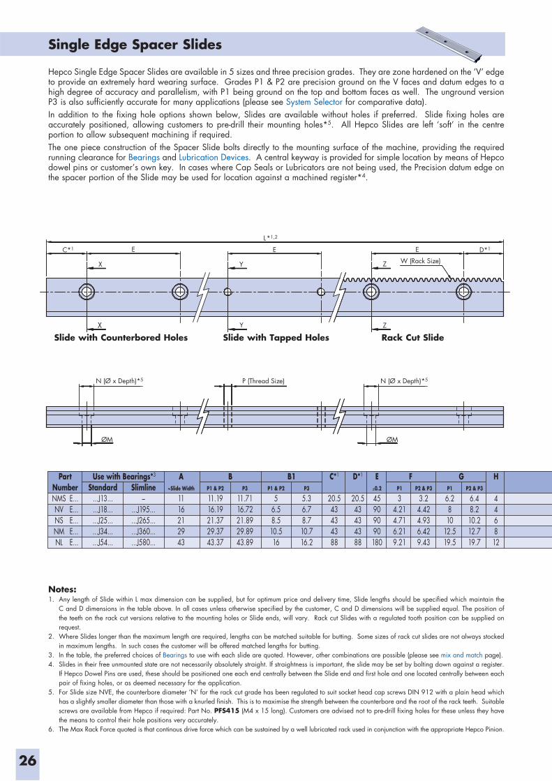
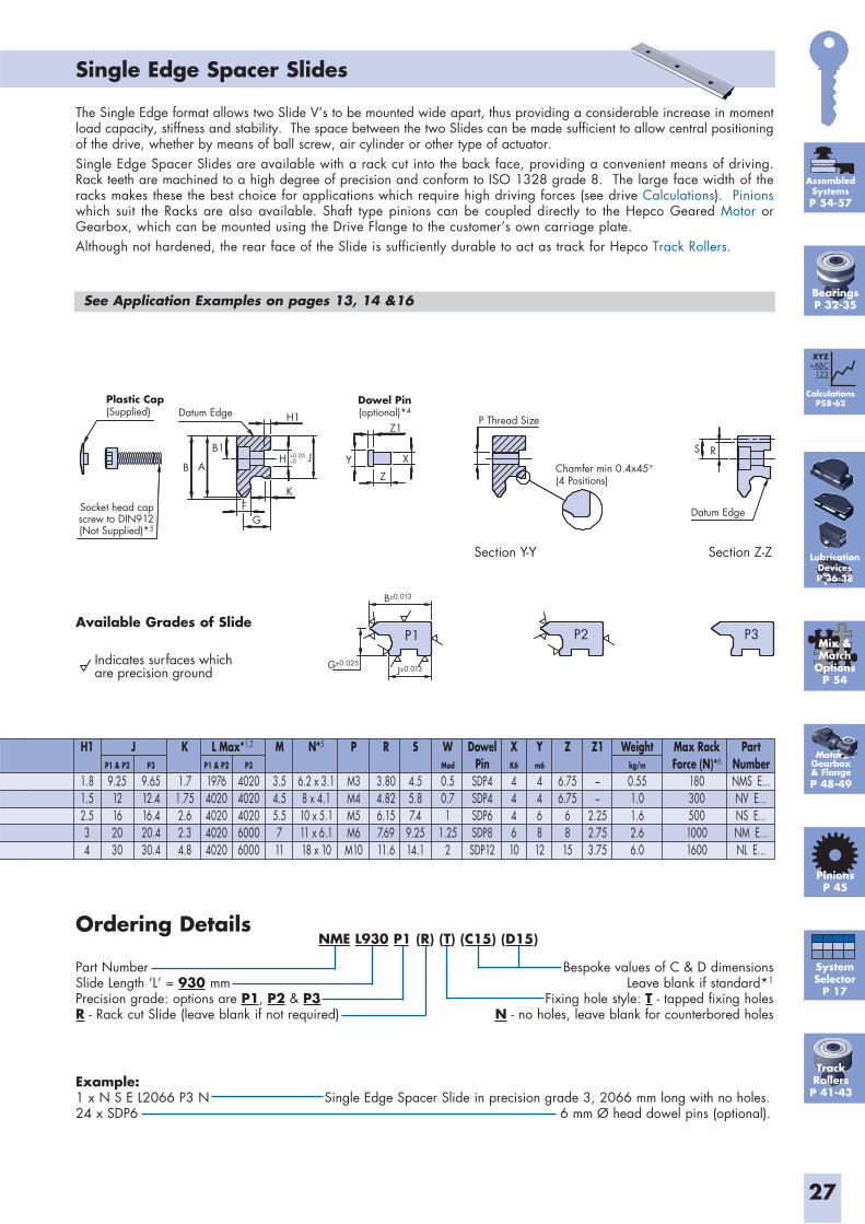
Single Edge Spacer Slides
X
N (Ø x Depth)*5
ØM ØM
P (Thread Size) N (Ø x Depth)*5
X
E
Y
Y
E
Z
E D*1
W (Rack Size)
Z
L*1,2
C*1
Hepco Single Edge Spacer Slides are available in 5 sizes and three precision grades. They are zone hardened on the ‘V’ edge to provide an extremely hard wearing surface. Grades P1 & P2 are precision ground on the V faces and datum edges to a high degree of accuracy and parallelism, with P1 being ground on the top and bottom faces as well. The unground version P3 is also sufficiently accurate for many applications (please see System Selector for comparative data).In addition to the fixing hole options shown below, Slides are available without holes if preferred. Slide fixing holes are accurately positioned, allowing customers to pre-drill their mounting holes*5. All Hepco Slides are left ‘soft’ in the centre portion to allow subsequent machining if required. The one piece construction of the Spacer Slide bolts directly to the mounting surface of the machine, providing the required running clearance for Bearings and Lubrication Devices. A central keyway is provided for simple location by means of Hepco dowel pins or customer’s own key. In cases where Cap Seals or Lubricators are not being used, the Precision datum edge on the spacer portion of the Slide may be used for location against a machined register*4.
Notes:1. Any length of Slide within L max dimension can be supplied, but for optimum price and delivery time, Slide lengths should be specified which maintain the
C and D dimensions in the table above. In all cases unless otherwise specified by the customer, C and D dimensions will be supplied equal. The position of the teeth on the rack cut versions relative to the mounting holes or Slide ends, will vary. Rack cut Slides with a regulated tooth position can be supplied on request.
2. Where Slides longer than the maximum length are required, lengths can be matched suitable for butting. Some sizes of rack cut slides are not always stocked in maximum lengths. In such cases the customer will be offered matched lengths for butting.
3. In the table, the preferred choices of Bearings to use with each slide are quoted. However, other combinations are possible (please see mix and match page).4. Slides in their free unmounted state are not necessarily absolutely straight. If straightness is important, the slide may be set by bolting down against a register.
If Hepco Dowel Pins are used, these should be positioned one each end centrally between the Slide end and first hole and one located centrally between each pair of fixing holes, or as deemed necessary for the application.
5. For Slide size NVE, the counterbore diameter ’N’ for the rack cut grade has been regulated to suit socket head cap screws DIN 912 with a plain head which has a slightly smaller diameter than those with a knurled finish. This is to maximise the strength between the counterbore and the root of the rack teeth. Suitable screws are available from Hepco if required: Part No. PFS415 (M4 x 15 long). Customers are advised not to pre-drill fixing holes for these unless they have the means to control their hole positions very accurately.
6. The Max Rack Force quoted is that continous drive force which can be sustained by a well lubricated rack used in conjunction with the appropriate Hepco Pinion.
Slide with Counterbored Holes Rack Cut SlideSlide with Tapped Holes
PartNumber
Use with Bearings*3
Standard...J13......J18......J25......J34......J54...
Slimline–
...J195...
...J265...
...J360...
...J580...
A~Slide Width
1116212943
C*1
20.543434388
D*1
20.543434388
E0.2
45909090180
H
446812
B B1 F GP1 & P2
11.1916.1921.3729.3743.37
P1 & P2
56.58.510.516
P2 & P3
3.24.424.936.429.43
P2 & P3
6.48.210.212.719.7
P3
11.7116.7221.8929.8943.89
P3
5.36.78.710.716.2
P1
34.214.716.219.21
P1
6.2810
12.519.5
E...E...E...E...E...
NMSNVNSNMNL
L Max*1,2H1
1.81.52.534
K
1.71.752.62.34.8
M
3.54.55.5711
N*5
6.2 x 3.18 x 4.110 x 5.111 x 6.118 x 10
Z1
––
2.252.753.75
Z
6.756.75
6815
DowelPin
SDP4SDP4SDP6SDP8SDP12
Max RackForce (N)*6
18030050010001600
WMod
0.50.71
1.252
Weightkg/m
0.551.01.62.66.0
XK6
444610
Ym6
446812
S
4.55.87.4
9.2514.1
R
3.804.826.157.6911.6
P
M3M4M5M6M10
JP1 & P2
9.2512162030
P1 & P2
19764020402040204020
P3
9.6512.416.420.430.4
P3
40204020402060006000
PartNumberNMS E...NV E...NS E...NM E...NL E...
27
Single Edge Spacer Slides
The Single Edge format allows two Slide V’s to be mounted wide apart, thus providing a considerable increase in moment load capacity, stiffness and stability. The space between the two Slides can be made sufficient to allow central positioning of the drive, whether by means of ball screw, air cylinder or other type of actuator. Single Edge Spacer Slides are available with a rack cut into the back face, providing a convenient means of driving. Rack teeth are machined to a high degree of precision and conform to ISO 1328 grade 8. The large face width of the racks makes these the best choice for applications which require high driving forces (see drive Calculations). Pinions which suit the Racks are also available. Shaft type pinions can be coupled directly to the Hepco Geared Motor or Gearbox, which can be mounted using the Drive Flange to the customer’s own carriage plate.Although not hardened, the rear face of the Slide is sufficiently durable to act as track for Hepco Track Rollers.
Socket head capscrew to DIN912(Not Supplied)*5
Indicates surfaces whichare precision ground
B
B1
H1
H
K
GF
J Y
Z
XS R
Z1
A
Section Y-Y Section Z-Z
Chamfer min 0.4x45°(4 Positions)
Datum Edge
P3P2P1
Dowel Pin(optional)*4
Plastic Cap(Supplied) Datum Edge
P Thread Size
+0.05–0
B±0.013
J±0.013G±0.025
Example:1 x N S E L2066 P3 N Single Edge Spacer Slide in precision grade 3, 2066 mm long with no holes.24 x SDP6 6 mm Ø head dowel pins (optional).
Ordering Details
Part NumberSlide Length ‘L’ = 930 mmPrecision grade: options are P1, P2 & P3R - Rack cut Slide (leave blank if not required)
Bespoke values of C & D dimensionsLeave blank if standard*1
Fixing hole style: T - tapped fixing holesN - no holes, leave blank for counterbored holes
See Application Examples on pages 13, 14 &16
Motor, Gearbox& FlangeP 48-49
Available Grades of Slide
TrackRollersP 41-43
SystemSelector
P 17
CalculationsP58-62
XYZ+ABC
123
PinionsP 45
Mix &Match
OptionsP 54
AssembledSystemsP 54-57
NME L930 P1 (R) (T) (C15) (D15)
BearingsP 32-35
LubricationDevicesP 36-38
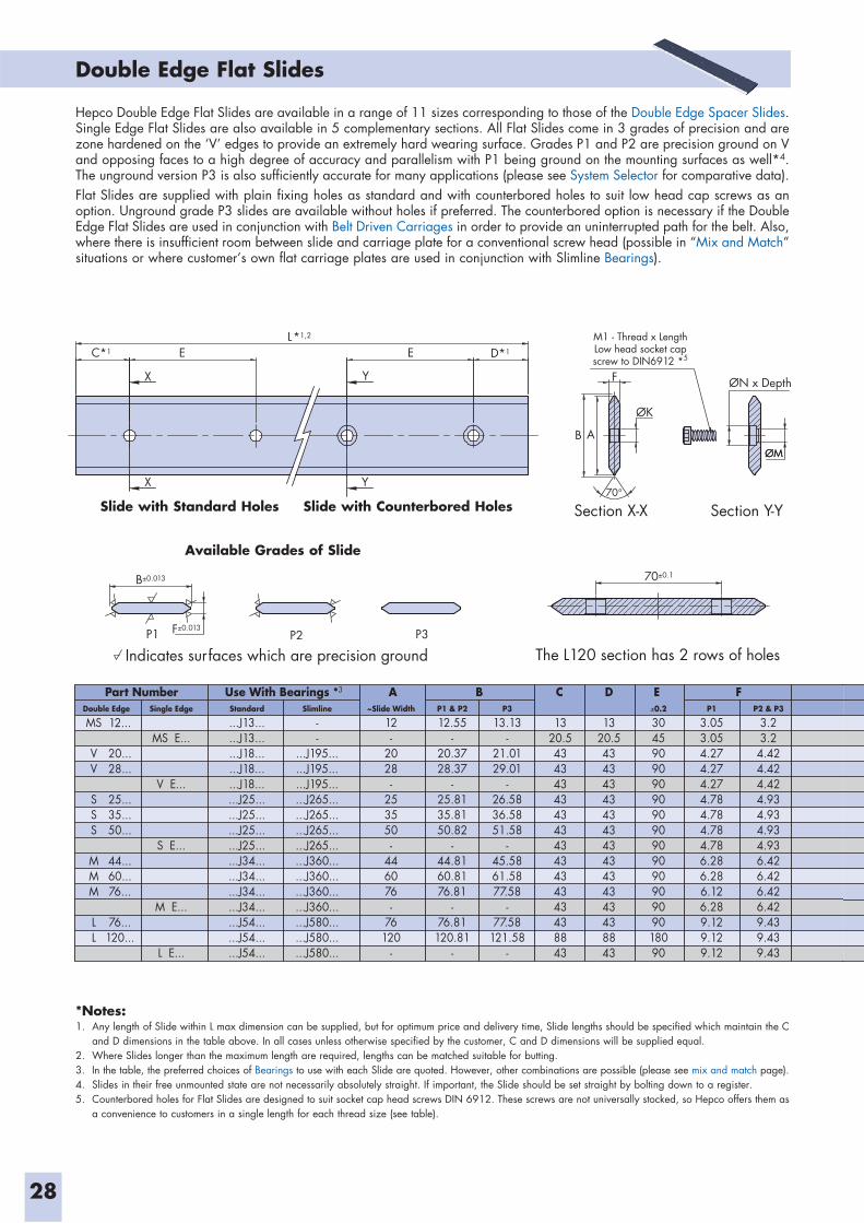
28
Double Edge Flat Slides
ØM
Indicates surfaces which are precision ground The L120 section has 2 rows of holes
Section X-X
X
B±0.013
F±0.013P1 P2 P3
X
E
B
70°
A
F
ØK
ØN x Depth
ØM
70±0.1
D*1
Y
Y
C*1 EL*1,2
Section Y-Y
M1 - Thread x LengthLow head socket capscrew to DIN6912 *5
Part Number A B FC D EUse With Bearings *3
Double Edge
MS
VV
SSS
MMM
LL
12...
20...28...
25...35...50...
44...60...76...
76...120...
Standard
...J13...
...J13...
...J18...
...J18...
...J18...
...J25...
...J25...
...J25...
...J25...
...J34...
...J34...
...J34...
...J34...
...J54...
...J54...
...J54...
Slimline
--
...J195...
...J195...
...J195...
...J265...
...J265...
...J265...
...J265...
...J360...
...J360...
...J360...
...J360...
...J580...
...J580...
...J580...
~Slide Width
12-
2028-
253550-
446076-
76120
-
P1 & P2
12.55-
20.3728.37
-25.8135.8150.82
-44.8160.8176.81
-76.81
120.81-
P3
13.13-
21.0129.01
-26.5836.5851.58
-45.5861.5877.58
-77.58
121.58-
0.2
304590909090909090909090909018090
P1
3.053.054.274.274.274.784.784.784.786.286.286.126.289.129.129.12
P2 & P3
3.23.2
4.424.424.424.934.934.934.936.426.426.426.429.439.439.43
1320.54343434343434343434343438843
1320.54343434343434343434343438843
Single Edge
MS E...
V E...
S E...
M E...
L E...
*Notes:1. Any length of Slide within L max dimension can be supplied, but for optimum price and delivery time, Slide lengths should be specified which maintain the C
and D dimensions in the table above. In all cases unless otherwise specified by the customer, C and D dimensions will be supplied equal. 2. Where Slides longer than the maximum length are required, lengths can be matched suitable for butting.3. In the table, the preferred choices of Bearings to use with each Slide are quoted. However, other combinations are possible (please see mix and match page).4. Slides in their free unmounted state are not necessarily absolutely straight. If important, the Slide should be set straight by bolting down to a register.5. Counterbored holes for Flat Slides are designed to suit socket cap head screws DIN 6912. These screws are not universally stocked, so Hepco offers them as
a convenience to customers in a single length for each thread size (see table).
Hepco Double Edge Flat Slides are available in a range of 11 sizes corresponding to those of the Double Edge Spacer Slides. Single Edge Flat Slides are also available in 5 complementary sections. All Flat Slides come in 3 grades of precision and are zone hardened on the ‘V’ edges to provide an extremely hard wearing surface. Grades P1 and P2 are precision ground on V and opposing faces to a high degree of accuracy and parallelism with P1 being ground on the mounting surfaces as well*4. The unground version P3 is also sufficiently accurate for many applications (please see System Selector for comparative data).Flat Slides are supplied with plain fixing holes as standard and with counterbored holes to suit low head cap screws as an option. Unground grade P3 slides are available without holes if preferred. The counterbored option is necessary if the Double Edge Flat Slides are used in conjunction with Belt Driven Carriages in order to provide an uninterrupted path for the belt. Also, where there is insufficient room between slide and carriage plate for a conventional screw head (possible in “Mix and Match” situations or where customer’s own flat carriage plates are used in conjunction with Slimline Bearings).
Slide with Standard Holes Slide with Counterbored Holes
Available Grades of Slide
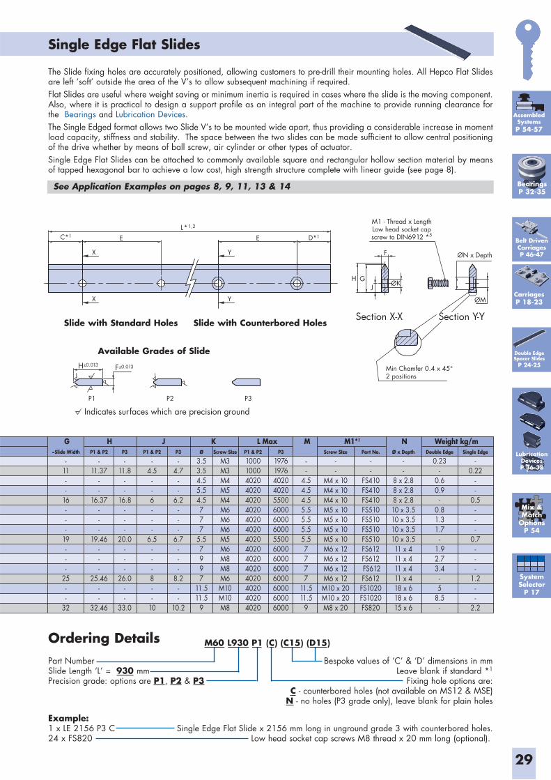
29
Example:1 x LE 2156 P3 C Single Edge Flat Slide x 2156 mm long in unground grade 3 with counterbored holes.24 x FS820 Low head socket cap screws M8 thread x 20 mm long (optional).
Bespoke values of ‘C’ & ‘D’ dimensions in mmLeave blank if standard *1
Fixing hole options are: C - counterbored holes (not available on MS12 & MSE)N - no holes (P3 grade only), leave blank for plain holes
Single Edge Flat Slides
M1 - Thread x LengthLow head socket capscrew to DIN6912 *5
ØN x Depth
P3P2P1
Min Chamfer 0.4 x 45°2 positions
ØM
ØKH
E
Y
YX
X
D*1C*1
L*1,2
E
G
F
J
Section Y-YSection X-X
Indicates surfaces which are precision ground
H±0.013 F±0.013
G H J K N Weight kg/mL Max~Slide Width
-
11--
16---
19---
25--
32
M M1*5
-
-4.54.54.55.55.55.55.57777
11.511.5
9
P1 & P2
-
11.37--
16.37---
19.46---
25.46--
32.46
P3
-
11.8--
16.8---
20.0---
26.0--
33.0
P1 & P2
-
4.5--6---
6.5---8--
10
Double Edge
0.23-
0.60.9
-0.81.31.7
-1.92.73.4
-5
8.5-
Single Edge
-0.22
--
0.5---
0.7---
1.2--
2.2
P1 & P2
1000100040204020402040204020402040204020402040204020402040204020
P3
1976197640204020550060006000600055006000600060006000600060006000
P3
-
4.7--
6.2---
6.7---
8.2--
10.2
Ø
3.53.54.55.54.5777
5.57997
11.511.5
9
Ø x Depth
--
8 x 2.88 x 2.88 x 2.810 x 3.510 x 3.510 x 3.510 x 3.511 x 411 x 411 x 411 x 418 x 618 x 615 x 6
Screw SIze
M3M3M4M5M4M6M6M6M5M6M8M8M6M10M10M8
Screw SIze
--
M4 x 10M4 x 10M4 x 10M5 x 10M5 x 10M5 x 10M5 x 10M6 x 12M6 x 12M6 x 12M6 x 12M10 x 20M10 x 20M8 x 20
Part No.
--
FS410FS410FS410FS510FS510FS510FS510FS612FS612 FS612FS612FS1020FS1020FS820
The Slide fixing holes are accurately positioned, allowing customers to pre-drill their mounting holes. All Hepco Flat Slides are left ‘soft’ outside the area of the V’s to allow subsequent machining if required. Flat Slides are useful where weight saving or minimum inertia is required in cases where the slide is the moving component. Also, where it is practical to design a support profile as an integral part of the machine to provide running clearance for the Bearings and Lubrication Devices.The Single Edged format allows two Slide V’s to be mounted wide apart, thus providing a considerable increase in moment load capacity, stiffness and stability. The space between the two slides can be made sufficient to allow central positioning of the drive whether by means of ball screw, air cylinder or other types of actuator.Single Edge Flat Slides can be attached to commonly available square and rectangular hollow section material by means of tapped hexagonal bar to achieve a low cost, high strength structure complete with linear guide (see page 8).
Ordering DetailsPart NumberSlide Length ‘L’ = 930 mmPrecision grade: options are P1, P2 & P3
See Application Examples on pages 8, 9, 11, 13 & 14
Slide with Standard Holes Slide with Counterbored Holes
Available Grades of Slide Double Edge Spacer Slides
P 24-25
Belt DrivenCarriagesP 46-47
M60 L930 P1 (C) (C15) (D15)
SystemSelector
P 17
Mix &Match
OptionsP 54
AssembledSystemsP 54-57
CarriagesP 18-23
BearingsP 32-35
LubricationDevicesP 36-38
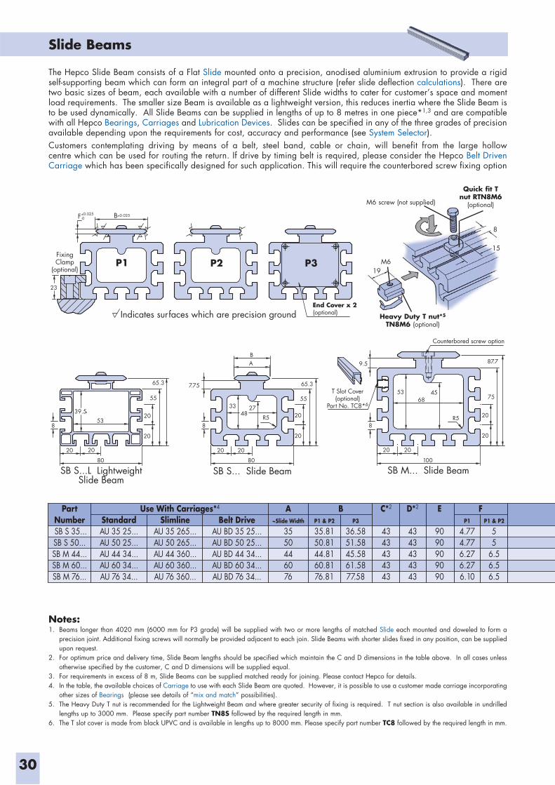
30
Slide Beams
9.5
P1 P2 P3
8
55
65.3
23
F B
FixingClamp
(optional)
53
39.5
80 80
20 20
100
8
20
20
754553
68
R5
87.7
2020 20
33 27
R548
7.75
8
BA
20
20
20
55
65.3
20
20
SB S...L LightweightSlide Beam
SB S... Slide Beam SB M... Slide Beam
Counterbored screw option
T Slot Cover(optional)
Part No. TC8*6
End Cover x 2(optional)
0.025-0
0.025
Indicates surfaces which are precision ground
PartNumber SB S 35...SB S 50...SB M 44...SB M 60...SB M 76...
Use With Carriages*4
StandardAU 35 25...AU 50 25...AU 44 34...AU 60 34...AU 76 34...
SlimlineAU 35 265...AU 50 265...AU 44 360...AU 60 360...AU 76 360...
Belt DriveAU BD 35 25...AU BD 50 25...AU BD 44 34...AU BD 60 34...AU BD 76 34...
A~Slide Width
3550446076
C*2
4343434343
D*2
4343434343
E
9090909090
B FP1 & P2
35.8150.8144.8160.8176.81
P1 & P2
55
6.56.56.5
P3
36.5851.5845.5861.5877.58
P1
4.774.776.276.276.10
The Hepco Slide Beam consists of a Flat Slide mounted onto a precision, anodised aluminium extrusion to provide a rigid self-supporting beam which can form an integral part of a machine structure (refer slide deflection calculations). There are two basic sizes of beam, each available with a number of different Slide widths to cater for customer’s space and moment load requirements. The smaller size Beam is available as a lightweight version, this reduces inertia where the Slide Beam is to be used dynamically. All Slide Beams can be supplied in lengths of up to 8 metres in one piece*1,3 and are compatible with all Hepco Bearings, Carriages and Lubrication Devices. Slides can be specified in any of the three grades of precision available depending upon the requirements for cost, accuracy and performance (see System Selector). Customers contemplating driving by means of a belt, steel band, cable or chain, will benefit from the large hollow centre which can be used for routing the return. If drive by timing belt is required, please consider the Hepco Belt Driven Carriage which has been specifically designed for such application. This will require the counterbored screw fixing option
Notes:1. Beams longer than 4020 mm (6000 mm for P3 grade) will be supplied with two or more lengths of matched Slide each mounted and doweled to form a
precision joint. Additional fixing screws will normally be provided adjacent to each join. Slide Beams with shorter slides fixed in any position, can be supplied upon request.
2. For optimum price and delivery time, Slide Beam lengths should be specified which maintain the C and D dimensions in the table above. In all cases unless otherwise specified by the customer, C and D dimensions will be supplied equal.
3. For requirements in excess of 8 m, Slide Beams can be supplied matched ready for joining. Please contact Hepco for details.4. In the table, the available choices of Carriage to use with each Slide Beam are quoted. However, it is possible to use a customer made carriage incorporating
other sizes of Bearings (please see details of “mix and match” possibilities).5. The Heavy Duty T nut is recommended for the Lightweight Beam and where greater security of fixing is required. T nut section is also available in undrilled
lengths up to 3000 mm. Please specify part number TN8S followed by the required length in mm.6. The T slot cover is made from black UPVC and is available in lengths up to 8000 mm. Please specify part number TC8 followed by the required length in mm.
Heavy Duty T nut*5 TN8M6 (optional)
M619
15
8
M6 screw (not supplied)
Quick fit T nut RTN8M6
(optional)
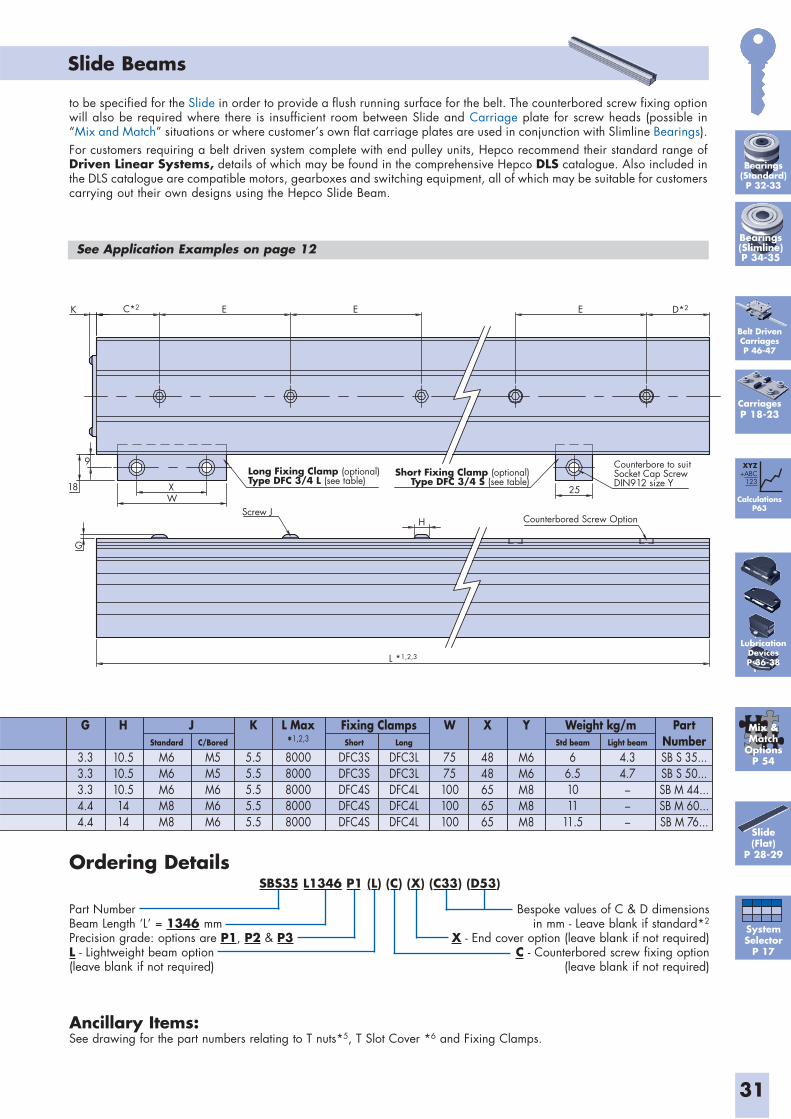
31
Slide Beams
K E
18
9
WX
G
Screw JH
L *1,2,3
Counterbore to suitSocket Cap ScrewDIN912 size Y
25
Counterbored Screw Option
Long Fixing Clamp (optional)Type DFC 3/4 L (see table)
Short Fixing Clamp (optional)Type DFC 3/4 S (see table)
E E D*2C*2
Ordering Details
Part NumberBeam Length ‘L’ = 1346 mmPrecision grade: options are P1, P2 & P3L - Lightweight beam option (leave blank if not required)
Bespoke values of C & D dimensions in mm - Leave blank if standard*2
X - End cover option (leave blank if not required) C - Counterbored screw fixing option
(leave blank if not required)
Ancillary Items:See drawing for the part numbers relating to T nuts*5, T Slot Cover *6 and Fixing Clamps.
L Max*1,2,3
80008000800080008000
G
3.33.33.34.44.4
K
5.55.55.55.55.5
W
7575100100100
PartNumberSB S 35...SB S 50...SB M 44...SB M 60...SB M 76...
X
4848656565
Y
M6M6M8M8M8
H
10.510.510.51414
J Weight kg/mFixing ClampsStandard
M6M6M6M8M8
Short
DFC3SDFC3SDFC4SDFC4SDFC4S
Long
DFC3LDFC3LDFC4LDFC4LDFC4L
C/Bored
M5M5M6M6M6
Std beam
66.51011
11.5
Light beam
4.34.7–––
to be specified for the Slide in order to provide a flush running surface for the belt. The counterbored screw fixing option will also be required where there is insufficient room between Slide and Carriage plate for screw heads (possible in “Mix and Match” situations or where customer’s own flat carriage plates are used in conjunction with Slimline Bearings).For customers requiring a belt driven system complete with end pulley units, Hepco recommend their standard range of Driven Linear Systems, details of which may be found in the comprehensive Hepco DLS catalogue. Also included in the DLS catalogue are compatible motors, gearboxes and switching equipment, all of which may be suitable for customers carrying out their own designs using the Hepco Slide Beam.
See Application Examples on page 12
CarriagesP 18-23
Belt DrivenCarriagesP 46-47
Slide(Flat)
P 28-29
Mix &Match
OptionsP 54
SystemSelector
P 17
CalculationsP63
XYZ+ABC
123
SBS35 L1346 P1 (L) (C) (X) (C33) (D53)
Bearings(Standard)P 32-33
Bearings(Slimline)P 34-35
LubricationDevicesP 36-38
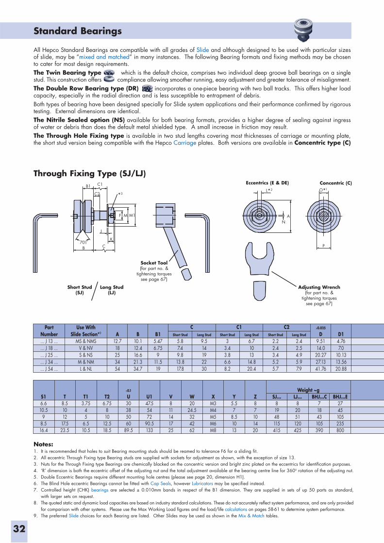
Standard Bearings
32
Notes:1. It is recommended that holes to suit Bearing mounting studs should be reamed to tolerance F6 for a sliding fit.2. All eccentric Through Fixing type Bearing studs are supplied with sockets for adjustment as shown, with the exception of size 13.3. Nuts for the Through Fixing type Bearings are chemically blacked on the concentric version and bright zinc plated on the eccentrics for identification purposes. 4. ‘R’ dimension is both the eccentric offset of the adjusting nut and the total adjustment available at the bearing centre line for 3600 rotation of the adjusting nut.5. Double Eccentric Bearings require different mounting hole centres (please see page 20, dimension H1). 6. The Blind Hole eccentric Bearings cannot be fitted with Cap Seals, however Lubricators may be specified instead.7. Controlled height (CHK) bearings are selected ± 0.010mm bands in respect of the B1 dimension. They are supplied in sets of up 50 parts as standard,
with larger sets on request.8. The quoted static and dynamic load capacities are based on industry standard calculations. These do not accurately reflect system performance, and are only provided
for comparison with other systems. Please use the Max Working Load figures and the load/life calculations on pages 58-61 to determine system performance.9. The preferred Slide choices for each Bearing are listed. Other Slides may be used as shown in the Mix & Match tables.
B1 C1
C2
B C
J
K70
F M M1 AN
P
Through Fixing Type (SJ/LJ) Eccentrics (E & DE) Concentric (C)
Short Stud(SJ)
Long Stud(LJ)
Adjusting Wrench(for part no. &
tightening torquessee page 67)
Socket Tool(for part no. &
tightening torquessee page 67)
PartNumber... J 13 ...... J 18 ...... J 25 ...... J 34 ...... J 54 ...
Use WithSlide Section*9
MS & NMSV & NVS & NS
M & NML & NL
A12.718253454
B10.112.416.621.334.7
B15.476.75
911.519
C C1 C2Short Stud
5.87.49.813.817.8
Long Stud
9.514192230
Short Stud
33.43.86.68.2
Long Stud
6.71013
14.820.4
Short Stud
2.22.43.45.25.7
Long Stud
2.42.54.95.97.9
0.025
D9.5114.0
20.2727.1341.76
D14.767.0
10.1313.5620.88
S16.610.5
98.516.4
T8.51012
17.523.5
T13.75
45
6.510.5
T26.75
810
12.518.5
0.1
U30385060
89.5
U147.55472
90.5133
V811141725
W20
24.5324262
XM3M4M5M6M8
Y5.57
8.51013
Z87101420
SJ...81948115415
LJ...8
2051120425
BHJ...C71843105390
BHJ...E2745105235800
Weight ~g
All Hepco Standard Bearings are compatible with all grades of Slide and although designed to be used with particular sizes of slide, may be “mixed and matched” in many instances. The following Bearing formats and fixing methods may be chosen to cater for most design requirements. The Twin Bearing type which is the default choice, comprises two individual deep groove ball bearings on a single stud. This construction offers some compliance allowing smoother running, easy adjustment and greater tolerance of misalignment.The Double Row Bearing type (DR) incorporates a one-piece bearing with two ball tracks. This offers higher load capacity, especially in the radial direction and is less susceptible to entrapment of debris.Both types of bearing have been designed specially for Slide system applications and their performance confirmed by rigorous testing. External dimensions are identical.The Nitrile Sealed option (NS) available for both bearing formats, provides a higher degree of sealing against ingress of water or debris than does the default metal shielded type. A small increase in friction may result.The Through Hole Fixing type is available in two stud lengths covering most thicknesses of carriage or mounting plate, the short stud version being compatible with the Hepco Carriage plates. Both versions are available in Concentric type (C)
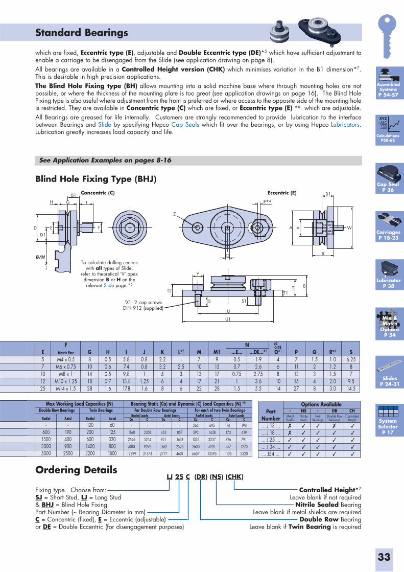
which are fixed, Eccentric type (E), adjustable and Double Eccentric type (DE)*5 which have sufficient adjustment to enable a carriage to be disengaged from the Slide (see application drawing on page 8).All bearings are available in a Controlled Height version (CHK) which minimises variation in the B1 dimension*7.This is desirable in high precision applications.The Blind Hole Fixing type (BH) allows mounting into a solid machine base where through mounting holes are not possible, or where the thickness of the mounting plate is too great (see application drawings on page 16). The Blind Hole Fixing type is also useful where adjustment from the front is preferred or where access to the opposite side of the mounting hole is restricted. They are available in Concentric type (C) which are fixed, or Eccentric type (E) *6 which are adjustable. All Bearings are greased for life internally. Customers are strongly recommended to provide lubrication to the interface between Bearings and Slide by specifying Hepco Cap Seals which fit over the bearings, or by using Hepco Lubricators. Lubrication greatly increases load capacity and life.
Standard Bearings
33
D
H
D1E
B/H
G
B1
F
Z
Q
Y
T2
S
U
U1
S1
T1T B
A V
B1
W
B
Blind Hole Fixing Type (BHJ) Eccentric (E)
‘X’ - 2 cap screws DIN 912 (supplied)
Concentric (C)
Ordering Details
Fixing type. Choose from:SJ = Short Stud, LJ = Long Stud & BHJ = Blind Hole FixingPart Number (~ Bearing Diameter in mm)C = Concentric (fixed), E = Eccentric (adjustable)or DE = Double Eccentric (for disengagement purposes)
Controlled Height*7
Leave blank if not requiredNitrile Sealed Bearing
Leave blank if metal shields are requiredDouble Row Bearing
Leave blank if Twin Bearing is required
PartNumber... J 13 ...... J 18 ...... J 25 ...... J 34 ...... J54 ...
-MetalShields
NSNitrileSeals
-Twin
Bearings
DRDouble Row
Bearings
CHControlled
Height
Options Available
See Application Examples on pages 8-16
CarriagesP 18-23
-190400900
2500
-600150030005000
12020060014003200
601253208001800
-
1168
2646
5018
12899
-
2301
5214
9293
21373
-
435
821
1362
2777
-
857
1618
2523
4601
265
593
1333
2600
6657
695
1438
3237
5291
13595
74
173
326
557
1136
194
419
791
1270
2320
Max Working Load Capacities (N) Bearing Static (Co) and Dynamic (C) Load Capacities (N) *8
Double Row Bearings Twin Bearings
Radial Axial
For Double Row Bearings For each of two Twin BearingsAxial Loads Axial LoadsRadial LoadsRadial Loads
AxialRadial Co C Co C Co C Co C
To calculate drilling centres with all types of Slide,
refer to theoretical ‘V’ apex dimension B or H on the relevant Slide page.*5
E57101225
FMetric Fine
M4 x 0.5M6 x 0.75
M8 x 1M10 x 1.25M14 x 1.5
G810141828
H0.50.60.50.71.6
I5.87.49.813.817.8
J0.80.81
1.251.6
K2.23.2568
L*2
-2.5346
M710131722
M1913172128
...E...0.50.70.75
11.5
P711131527
O*1
4681014
...DE...*5
1.92.6
2.753.65.5
Q1.52348
R*4
1.01.21.52.03.0
S6.25
87
9.514.5
N +0-0.03
Cap SealP 36
LubricatorP 38
LJ 25 C (DR) (NS) (CHK)
SlidesP 24-31
Mix &Match
OptionsP 54
SystemSelector
P 17
CalculationsP58-62
XYZ+ABC
123
AssembledSystemsP 54-57
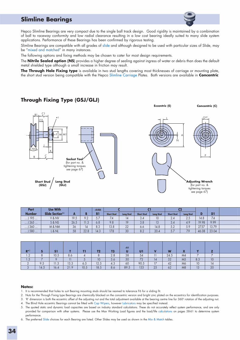
Slimline Bearings
34
Hepco Slimline Bearings are very compact due to the single ball track design. Good rigidity is maintained by a combination of ball to raceway conformity and low radial clearance resulting in a low cost bearing ideally suited to many slide system applications. Performance of these Bearings has been confirmed by rigorous testing.Slimline Bearings are compatible with all grades of slide and although designed to be used with particular sizes of Slide, may be “mixed and matched” in many instances. The following options and fixing methods may be chosen to cater for most design requirements. The Nitrile Sealed option (NS) provides a higher degree of sealing against ingress of water or debris than does the default metal shielded type although a small increase in friction may result.The Through Hole Fixing type is available in two stud lengths covering most thicknesses of carriage or mounting plate, the short stud version being compatible with the Hepco Slimline Carriage Plates. Both versions are available in Concentric
Notes:1. It is recommended that holes to suit Bearing mounting studs should be reamed to tolerance F6 for a sliding fit.2. Nuts for the Through Fixing type Bearings are chemically blacked on the concentric version and bright zinc plated on the eccentrics for identification purposes. 3. ‘R’ dimension is both the eccentric offset of the adjusting nut and the total adjustment available at the bearing centre line for 3600 rotation of the adjusting nut.4. The Blind Hole eccentric Bearings cannot be fitted with Cap Wipers, however Lubricators may be specified instead.5. The quoted static and dynamic load capacities are based on industry standard calculations. These do not accurately reflect system performance, and are only
provided for comparison with other systems. Please use the Max Working Load figures and the load/life calculations on pages 58-61 to determine system performance.
6. The preferred Slide choices for each Bearing are listed. Other Slides may be used as shown in the Mix & Match tables.
B1 C1
C2
70
B C
K
J
F M M1
L
A
N
P
Through Fixing Type (GSJ/GLJ) Eccentric (E) Concentric (C)
Short Stud(GSJ)
Long Stud(GLJ)
Adjusting Wrench(for part no. &
tightening torquessee page 67)
Socket Tool(for part no. &
tightening torquessee page 67)
PartNumber... J 195 ...... J 265 ...... J 360 ...... J 580 ...
Use WithSlide Section*6
V & NVS & NS
M & NML & NL
A19.526.53658
B9.211.314
22.8
0.025
B15.76.88.314.3
C C1 C2Short Stud
7.49.813.817.8
Long Stud
14192230
Short Stud
3.43.86.68.2
Long Stud
1013
14.820.4
Short Stud
2.43.45.25.7
Long Stud
2.54.95.97.9
D14.819.9827.5746.08
D17.4
9.9913.7923.04
R*3
1.21.523
S87
9.514.5
S110.5
911.316.4
T8.611
13.321.9
T145
6.510.5
T2810
12.518.5
T32.83.64.38.6
0.1
U385060
89.5
U15472
90.5133
V11141725
W24.5324262
XM4M5M6M8
Y7
8.51013
Z7101420
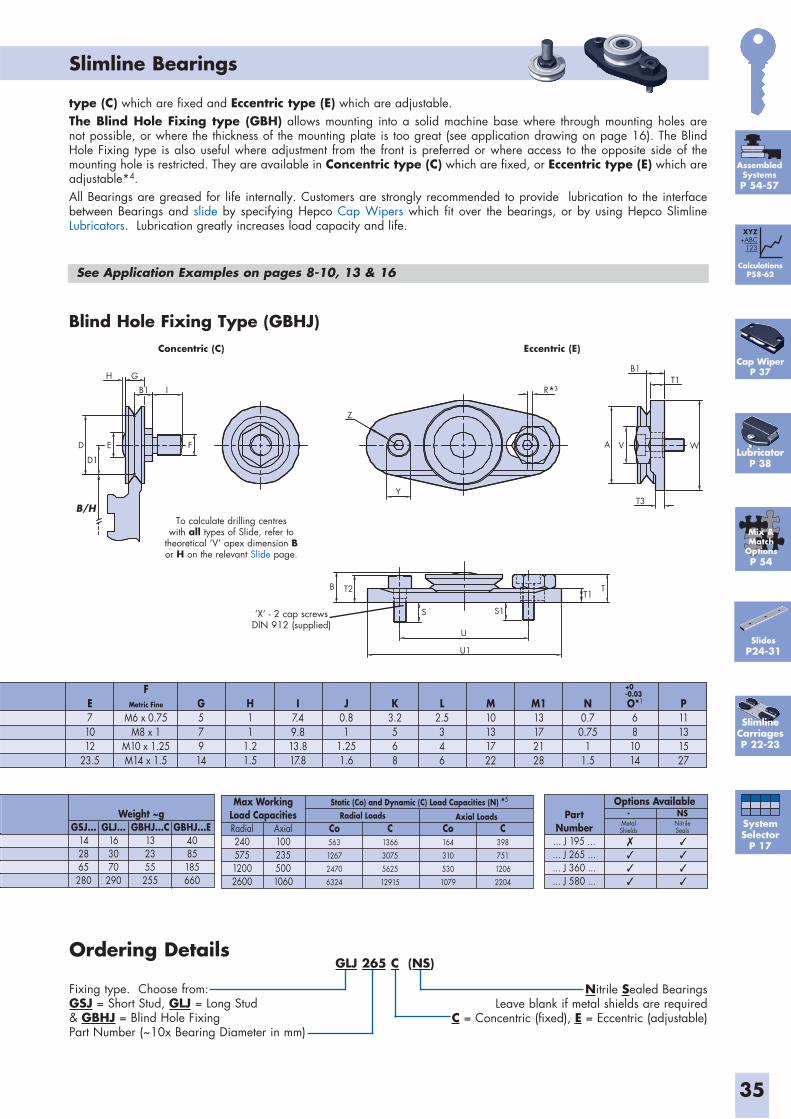
Slimline Bearings
35
type (C) which are fixed and Eccentric type (E) which are adjustable.The Blind Hole Fixing type (GBH) allows mounting into a solid machine base where through mounting holes are not possible, or where the thickness of the mounting plate is too great (see application drawing on page 16). The Blind Hole Fixing type is also useful where adjustment from the front is preferred or where access to the opposite side of the mounting hole is restricted. They are available in Concentric type (C) which are fixed, or Eccentric type (E) which are adjustable*4. All Bearings are greased for life internally. Customers are strongly recommended to provide lubrication to the interface between Bearings and slide by specifying Hepco Cap Wipers which fit over the bearings, or by using Hepco Slimline Lubricators. Lubrication greatly increases load capacity and life.
B/H
H
D
D1
E
G
B1 I
F
Z
Y
B1T1
A V
T3
W
B T2
S
U
U1
S1
T1T
Blind Hole Fixing Type (GBHJ) Eccentric (E)
‘X’ - 2 cap screws DIN 912 (supplied)
Concentric (C)
Ordering Details
Fixing type. Choose from:GSJ = Short Stud, GLJ = Long Stud & GBHJ = Blind Hole FixingPart Number (~10x Bearing Diameter in mm)
Nitrile Sealed BearingsLeave blank if metal shields are required
C = Concentric (fixed), E = Eccentric (adjustable)
E71012
23.5
FMetric Fine
M6 x 0.75M8 x 1
M10 x 1.25M14 x 1.5
G57914
H11
1.21.5
I7.49.813.817.8
J0.81
1.251.6
K3.2568
L2.5346
M10131722
M113172128
N0.7
0.751
1.5
P11131527
O*1
681014
+0-0.03
LubricatorP 38
Slimline CarriagesP 22-23
See Application Examples on pages 8-10, 13 & 16
PartNumber... J 195 ...... J 265 ...... J 360 ...... J 580 ...
-MetalShields
Options Available
�
�
�
�
�
�
�
�
NSNitrileSealsRadial
24057512002600
Axial1002355001060
Co563
1267
2470
6324
C1366
3075
5625
12915
Co164
310
530
1079
C398
751
1206
2204
Max WorkingLoad Capacities
Static (Co) and Dynamic (C) Load Capacities (N) *5
Radial Loads Axial Loads
To calculate drilling centres with all types of Slide, refer to
theoretical ‘V’ apex dimension B or H on the relevant Slide page.
Cap WiperP 37
GSJ...142865280
GLJ...163070
290
GBHJ...C132355255
GBHJ...E4085185660
Weight ~g
GLJ 265 C (NS)
Mix &Match
OptionsP 54
SystemSelector
P 17
CalculationsP58-62
XYZ+ABC
123
AssembledSystemsP 54-57
SlidesP24-31
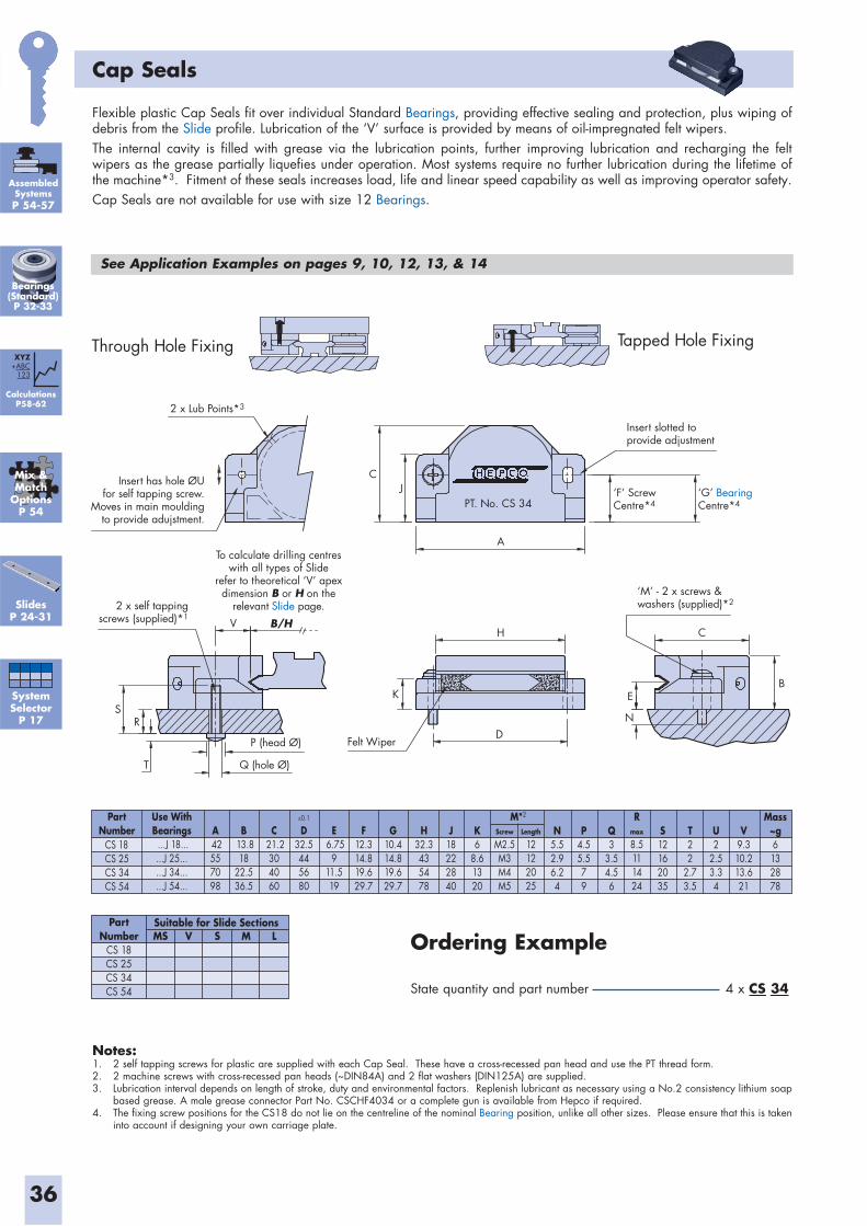
36
Cap Seals
Notes:1. 2 self tapping screws for plastic are supplied with each Cap Seal. These have a cross-recessed pan head and use the PT thread form.2. 2 machine screws with cross-recessed pan heads (~DIN84A) and 2 flat washers (DIN125A) are supplied.3. Lubrication interval depends on length of stroke, duty and environmental factors. Replenish lubricant as necessary using a No.2 consistency lithium soap based grease. A male grease connector Part No. CSCHF4034 or a complete gun is available from Hepco if required. 4. The fixing screw positions for the CS18 do not lie on the centreline of the nominal Bearing position, unlike all other sizes. Please ensure that this is taken into account if designing your own carriage plate.
Through Hole Fixing Tapped Hole Fixing
PT. No. CS 34
Insert has hole ØUfor self tapping screw.
Moves in main mouldingto provide adujstment.
2 x self tappingscrews (supplied)*1
2 x Lub Points*3
H
A
CJ
N
EB
‘M’ - 2 x screws &washers (supplied)*2
‘F’ ScrewCentre*4
‘G’ BearingCentre*4
Insert slotted toprovide adjustment
To calculate drilling centreswith all types of Slide
refer to theoretical ‘V’ apexdimension B or H on the
relevant Slide page.
V
Q (hole Ø)
P (head Ø)
S
T
K
DR
Felt Wiper
B/HC
PartNumber
Use WithBearings ...J 18......J 25......J 34......J 54...
A 42557098
B 13.8
1822.536.5
C 21.2
304060
F12.314.819.629.7
G10.414.819.629.7
H32.3435478
J18222840
K6
8.61320
N5.52.96.24
P4.55.579
S12162035
T22
2.73.5
U2
2.53.34
V9.310.213.621
Q3
3.54.56
Mass~g6132878
Screw
M2.5M3M4M5
Length
12122025
M*20.1
D32.5445680
E 6.75
911.519
Rmax
8.5111424
CS 18CS 25CS 34CS 54
Flexible plastic Cap Seals fit over individual Standard Bearings, providing effective sealing and protection, plus wiping of debris from the Slide profile. Lubrication of the ‘V’ surface is provided by means of oil-impregnated felt wipers.The internal cavity is filled with grease via the lubrication points, further improving lubrication and recharging the felt wipers as the grease partially liquefies under operation. Most systems require no further lubrication during the lifetime of the machine*3. Fitment of these seals increases load, life and linear speed capability as well as improving operator safety.Cap Seals are not available for use with size 12 Bearings.
See Application Examples on pages 9, 10, 12, 13, & 14
Ordering Example
State quantity and part number 4 x CS 34
PartNumber
CS 18CS 25CS 34CS 54
Suitable for Slide SectionsMS V S M L
AssembledSystemsP 54-57
CalculationsP58-62
XYZ+ABC
123
Bearings(Standard)P 32-33
Mix &Match
OptionsP 54
SlidesP 24-31
SystemSelector
P 17
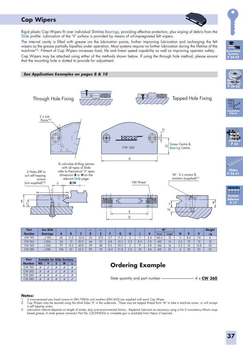
37
Cap Wipers
Rigid plastic Cap Wipers fit over individual Slimline Bearings, providing effective protection, plus wiping of debris from the Slide profile. Lubrication of the ‘V’ surface is provided by means of oil-impregnated felt wipers.The internal cavity is filled with grease via the lubrication points, further improving lubrication and recharging the felt wipers as the grease partially liquefies under operation. Most systems require no further lubrication during the lifetime of the machine*3. Fitment of Cap Wipers increases load, life and linear speed capability as well as improving operator safety.Cap Wipers may be attached using either of the methods shown below. If using the through hole method, please ensure that the mounting hole is slotted to provide for adjustment.
See Application Examples on pages 8 & 10
Notes:1. 2 cross-recessed pan head screws to DIN 7985A and washers (DIN 433) are supplied with each Cap Wiper. 2. Cap Wipers may be secured using the blind holes ‘K’ in the underside. These may be tapped thread form ‘M’ to take a machine screw, or will accept a self tapping screw.3. Lubrication interval depends on length of stroke, duty and environmental factors. Replenish lubricant as necessary using a No.2 consistency lithium soap based grease. A male grease connector Part No. CSCHF4034 or complete gun is available from Hepco if required.
Through Hole Fixing Tapped Hole Fixing
CW 360
2 Holes ØK tosuit self tapping
screws(not supplied)*2
2 x Lub. Points*3
To calculate drilling centreswith all types of Slide
refer to theoretical ‘V’ apexdimension B or H on the
relevant Slide page.V
E
F
N
PP
D
A
H
G
BJ
C
Felt Wiper
Screw Centre &Bearing Centre
‘M’ - 2 x screws &washers (supplied)*1
B/H
Ordering Example
State quantity and part number 4 x CW 360
PartNumberCW 195CW 265CW 360CW 580
Suitable for Slide SectionsMS✗
✗
✗
✗
V✓
✗
✗
✗
S✗
✓
✗
✗
M✗
✗
✓
✗
L✗
✗
✗
✓
PartNumberCW 195CW 265CW 360CW 580
Use WithBearings ...J 195......J 265......J 360......J 580...
A435472106
B11.213
15.525
C 22.830.340.863.3
F5.76.88.314.3
G11.315.320.531.8
H2
2.53
3.5
J7
8.5918
K2.42.83.84.8
N3
5.55.54
P8.5101020
V7.410
13.823
Weight~g6102055
Screw
M2.5M3M4M5
Length
12161625
M*10.1
D35445990
0.1
E27.5354874
SlidesP 24-31
Mix &Match
OptionsP 54
SystemSelector
P 17
AssembledSystemsP 54-57
CalculationsP58-62
XYZ+ABC
123
Bearings(Slimline)P 34-35
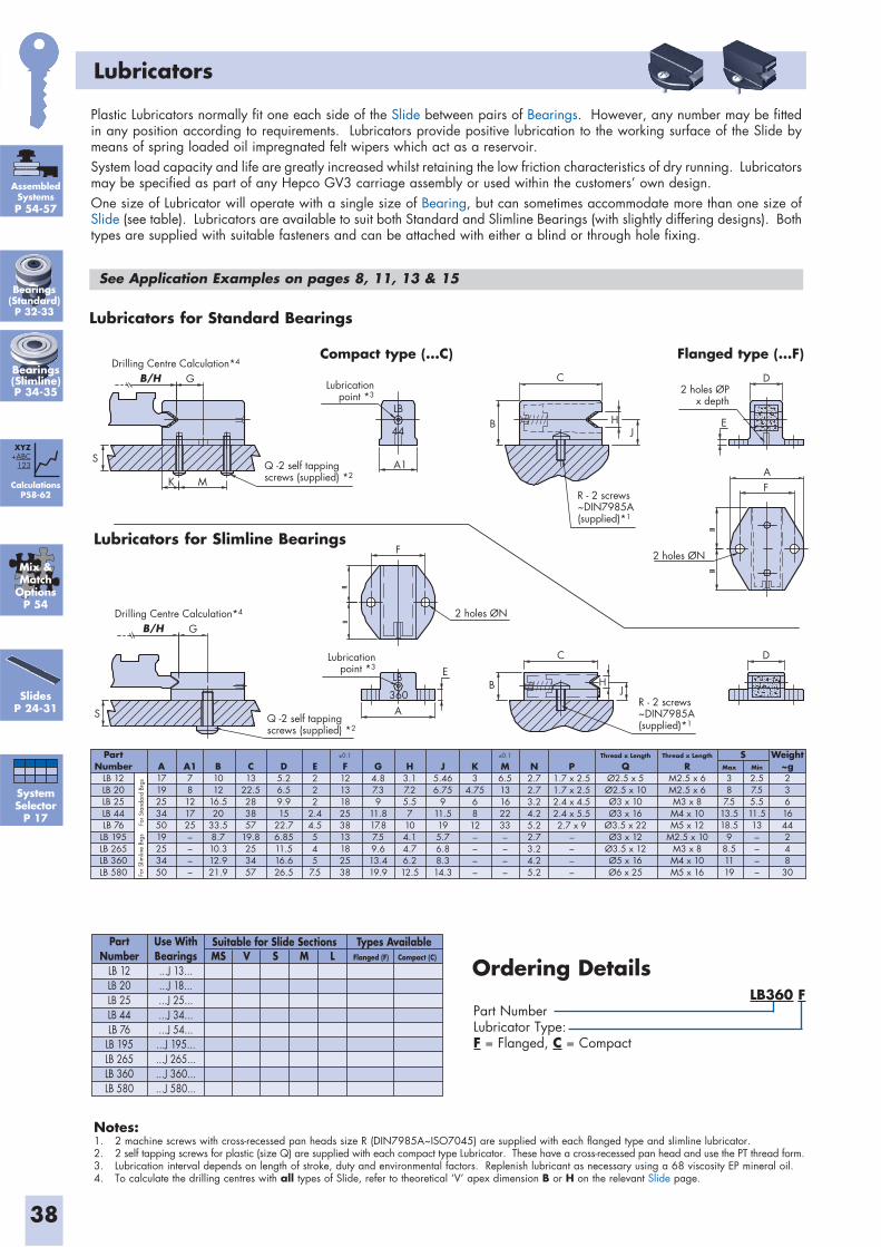
38
Lubricators
Plastic Lubricators normally fit one each side of the Slide between pairs of Bearings. However, any number may be fitted in any position according to requirements. Lubricators provide positive lubrication to the working surface of the Slide by means of spring loaded oil impregnated felt wipers which act as a reservoir.System load capacity and life are greatly increased whilst retaining the low friction characteristics of dry running. Lubricators may be specified as part of any Hepco GV3 carriage assembly or used within the customers’ own design.One size of Lubricator will operate with a single size of Bearing, but can sometimes accommodate more than one size of Slide (see table). Lubricators are available to suit both Standard and Slimline Bearings (with slightly differing designs). Both types are supplied with suitable fasteners and can be attached with either a blind or through hole fixing.
See Application Examples on pages 8, 11, 13 & 15
Drilling Centre Calculation*4
LB
K M
S
G
A1
B
DC
B
F
=
=
E
A 360
LB HJ
C
HJ
E
D
AF
44
Q -2 self tappingscrews (supplied) *2
Q -2 self tappingscrews (supplied) *2
R - 2 screws~DIN7985A(supplied)*1
R - 2 screws~DIN7985A(supplied)*1
2 holes ØPx depth
2 holes ØN
2 holes ØN
B/H
Drilling Centre Calculation*4
G
S
B/H
Lubricationpoint *3
Lubricationpoint *3
Notes:1. 2 machine screws with cross-recessed pan heads size R (DIN7985A~ISO7045) are supplied with each flanged type and slimline lubricator.2. 2 self tapping screws for plastic (size Q) are supplied with each compact type Lubricator. These have a cross-recessed pan head and use the PT thread form.3. Lubrication interval depends on length of stroke, duty and environmental factors. Replenish lubricant as necessary using a 68 viscosity EP mineral oil.4. To calculate the drilling centres with all types of Slide, refer to theoretical ‘V’ apex dimension B or H on the relevant Slide page.
PartNumber
LB 12LB 20LB 25LB 44LB 76
LB 195LB 265LB 360LB 580 Fo
r Slim
line
Brgs
For S
tand
ard
Brgs
A171925345019253450
A178121725––––
B1012
16.520
33.58.710.312.921.9
C13
22.5283857
19.8253457
D5.26.59.915
22.76.8511.516.626.5
E222
2.44.5545
7.5
F121318253813182538
G4.87.39
11.817.87.59.613.419.9
H3.17.25.57104.14.76.212.5
J5.466.75
911.5195.76.88.314.3
K3
4.756812––––
M6.513162233––––
N2.72.73.24.25.22.73.24.25.2
P1.7 x 2.51.7 x 2.52.4 x 4.52.4 x 5.52.7 x 9
––––
Thread x Length
QØ2.5 x 5Ø2.5 x 10Ø3 x 10Ø3 x 16
Ø3.5 x 22Ø3 x 12
Ø3.5 x 12Ø5 x 16Ø6 x 25
Max
38
7.513.518.5
98.51119
Min
2.57.55.511.513––––
Thread x Length
RM2.5 x 6M2.5 x 6M3 x 8M4 x 10M5 x 12
M2.5 x 10M3 x 8M4 x 10M5 x 16
Weight~g2361644248
30
S0.1 0.1
PartNumber
LB 12LB 20LB 25LB 44LB 76
LB 195LB 265LB 360LB 580
Use WithBearings...J 13......J 18......J 25......J 34......J 54......J 195......J 265......J 360......J 580...
Suitable for Slide Sections Types AvailableMS Flanged (F) Compact (C)V S M L
Ordering Details
Compact type (...C) Flanged type (...F)
Lubricators for Slimline Bearings
Lubricators for Standard Bearings
AssembledSystemsP 54-57
CalculationsP58-62
XYZ+ABC
123
SlidesP 24-31
Mix &Match
OptionsP 54
SystemSelector
P 17
Bearings(Standard)P 32-33
Bearings(Slimline)P 34-35
LB360 FPart NumberLubricator Type:F = Flanged, C = Compact
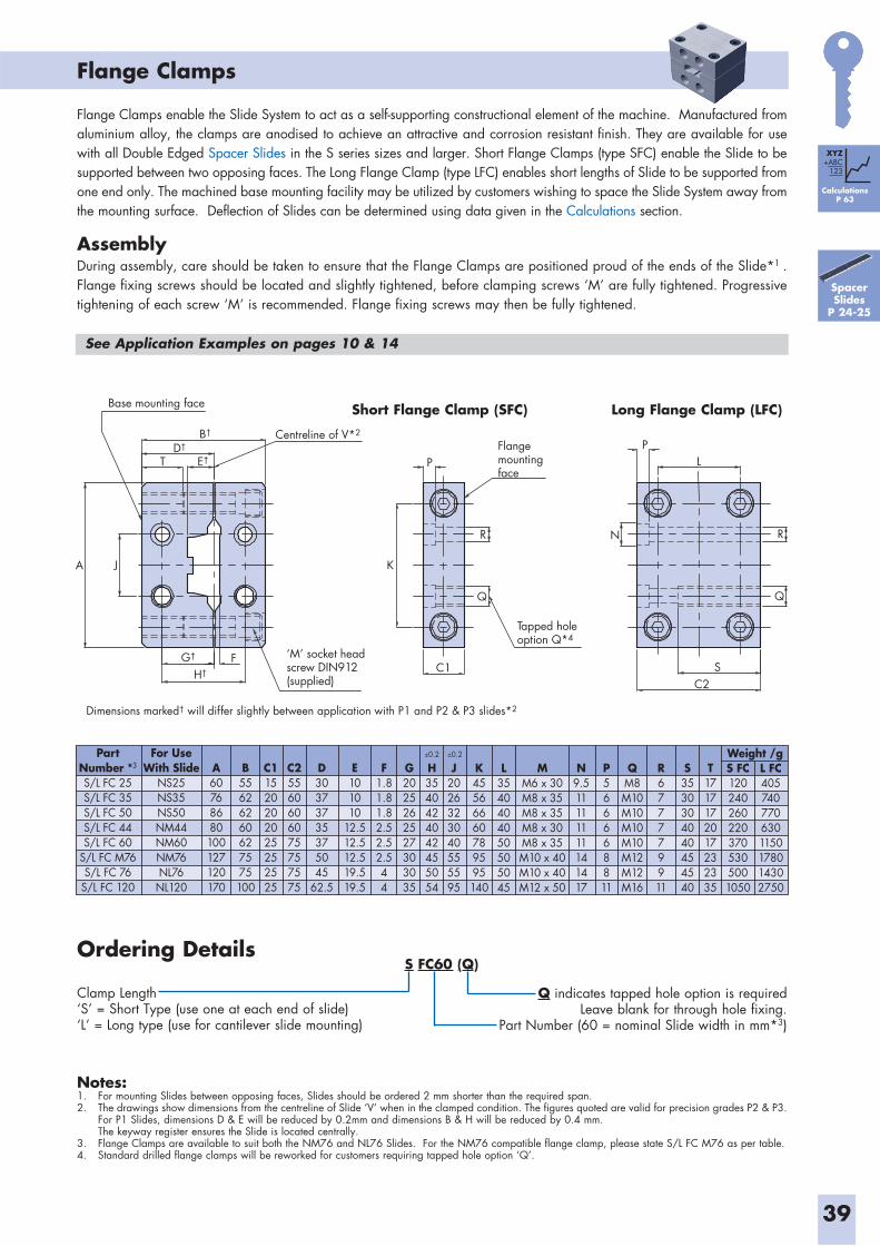
39
Flange Clamps
Flange Clamps enable the Slide System to act as a self-supporting constructional element of the machine. Manufactured from aluminium alloy, the clamps are anodised to achieve an attractive and corrosion resistant finish. They are available for use with all Double Edged Spacer Slides in the S series sizes and larger. Short Flange Clamps (type SFC) enable the Slide to be supported between two opposing faces. The Long Flange Clamp (type LFC) enables short lengths of Slide to be supported from one end only. The machined base mounting facility may be utilized by customers wishing to space the Slide System away from the mounting surface. Deflection of Slides can be determined using data given in the Calculations section.
AssemblyDuring assembly, care should be taken to ensure that the Flange Clamps are positioned proud of the ends of the Slide*1 . Flange fixing screws should be located and slightly tightened, before clamping screws ‘M’ are fully tightened. Progressive tightening of each screw ‘M’ is recommended. Flange fixing screws may then be fully tightened.
Notes:1. For mounting Slides between opposing faces, Slides should be ordered 2 mm shorter than the required span.2. The drawings show dimensions from the centreline of Slide ‘V’ when in the clamped condition. The figures quoted are valid for precision grades P2 & P3. For P1 Slides, dimensions D & E will be reduced by 0.2mm and dimensions B & H will be reduced by 0.4 mm. The keyway register ensures the Slide is located centrally.3. Flange Clamps are available to suit both the NM76 and NL76 Slides. For the NM76 compatible flange clamp, please state S/L FC M76 as per table.4. Standard drilled flange clamps will be reworked for customers requiring tapped hole option ‘Q’.
Flangemountingface
Tapped holeoption Q*4
Dimensions marked† will differ slightly between application with P1 and P2 & P3 slides*2
G†
H†
D†
E†T
B†
N
PL
RR
P
Base mounting face
KA
F ‘M’ socket headscrew DIN912(supplied)
J
C1
SC2
Centreline of V*2
Long Flange Clamp (LFC)Short Flange Clamp (SFC)
Ordering Details
Clamp Length‘S’ = Short Type (use one at each end of slide)‘L’ = Long type (use for cantilever slide mounting)
Q indicates tapped hole option is requiredLeave blank for through hole fixing.
Part Number (60 = nominal Slide width in mm*3)
PartNumber *3
S/L FC 25S/L FC 35S/L FC 50S/L FC 44S/L FC 60
S/L FC M76S/L FC 76
S/L FC 120
For UseWith Slide
NS25NS35NS50NM44NM60NM76NL76
NL120
A60768680100127120170
B55626260627575100
C11520202025252525
C25560606075757575
D30373735375045
62.5
E101010
12.512.512.519.519.5
F1.81.81.82.52.52.544
G2025262527303035
H3540424042455054
J2026323040555595
K45566660789595140
T1717172017232335
S3530304040454540
R677779911
QM8M10M10M10M10M12M12M16
P566668811
N9.511111111141417
MM6 x 30M8 x 35M8 x 35M8 x 30M8 x 35M10 x 40M10 x 40M12 x 50
L3540404050505045
S FC1202402602203705305001050
L FC4057407706301150178014302750
Weight /g0.2 0.2
Spacer Slides
P 24-25
See Application Examples on pages 10 & 14
CalculationsP 63
XYZ+ABC
123
S FC60 (Q)
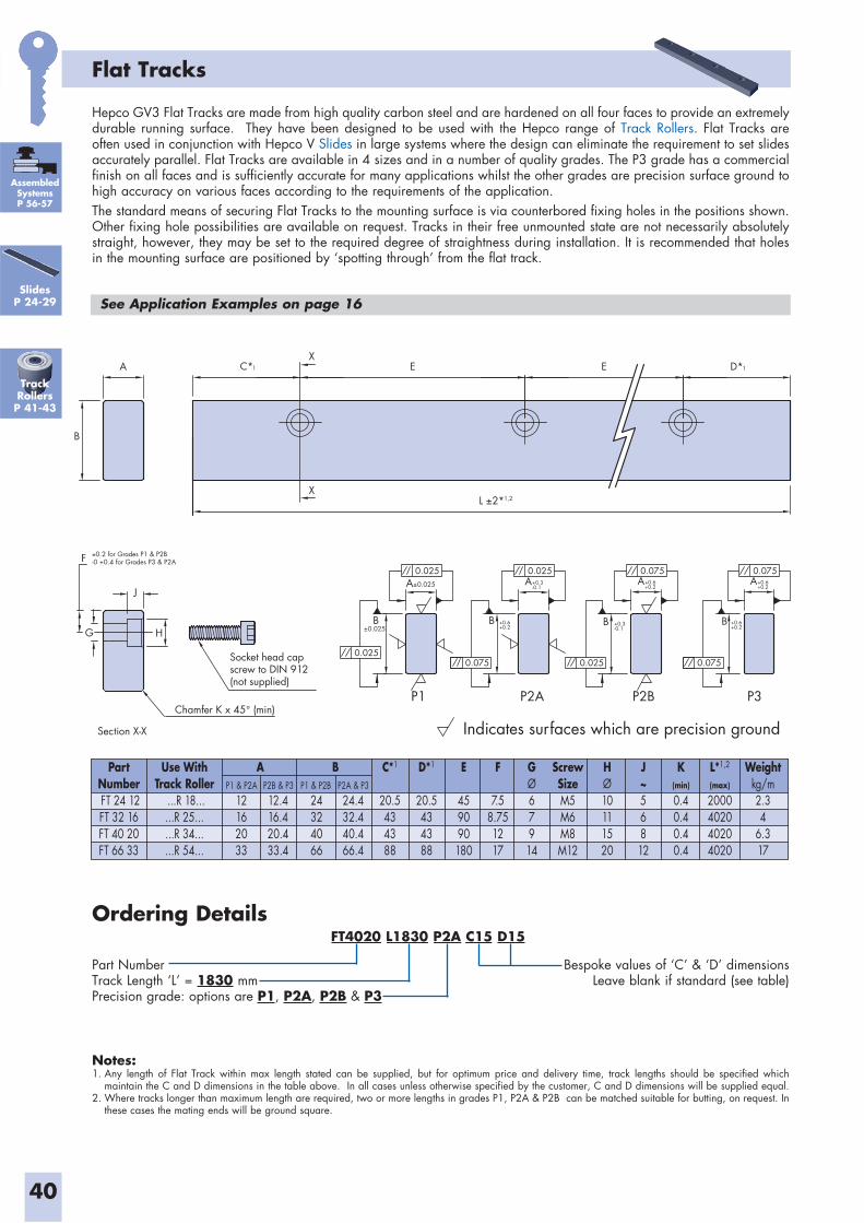
40
Flat Tracks
Hepco GV3 Flat Tracks are made from high quality carbon steel and are hardened on all four faces to provide an extremely durable running surface. They have been designed to be used with the Hepco range of Track Rollers. Flat Tracks are often used in conjunction with Hepco V Slides in large systems where the design can eliminate the requirement to set slides accurately parallel. Flat Tracks are available in 4 sizes and in a number of quality grades. The P3 grade has a commercial finish on all faces and is sufficiently accurate for many applications whilst the other grades are precision surface ground to high accuracy on various faces according to the requirements of the application.The standard means of securing Flat Tracks to the mounting surface is via counterbored fixing holes in the positions shown. Other fixing hole possibilities are available on request. Tracks in their free unmounted state are not necessarily absolutely straight, however, they may be set to the required degree of straightness during installation. It is recommended that holes in the mounting surface are positioned by ‘spotting through’ from the flat track.
PartNumber FT 24 12FT 32 16FT 40 20FT 66 33
Use WithTrack Roller
...R 18......R 25......R 34......R 54...
12162033
12.416.420.433.4
24324066
24.432.440.466.4
C*1
20.5434388
D*1
20.5434388
HØ10111520
J~56812
K(min)
0.40.40.40.4
L*1,2
(max)
2000402040204020
Weightkg/m2.34
6.317
ScrewSizeM5M6M8M12
GØ67914
F
7.58.751217
E
459090180
BAP1 & P2A P2B & P3 P1 & P2B P2A & P3
Section X-X
F
J
H
Chamfer K x 45° (min)
Socket head capscrew to DIN 912(not supplied)
Indicates surfaces which are precision ground
±0.2 for Grades P1 & P2B-0 +0.4 for Grades P3 & P2A
P3P2BP2AP1
G
A±0.025
L ±2*
E
X
C*X
D*
0.025 0.025 0.075 0.075
0.0250.075 0.0750.025
B
A 1
1,2
E
+0.6
1
B B
A+0.2
+0.3-0.1
A +0.6+0.2
A
B±0.025
+0.6+0.2
+0.3-0.1 +0.2
+0.6B
Ordering Details
Part NumberTrack Length ‘L’ = 1830 mmPrecision grade: options are P1, P2A, P2B & P3
Bespoke values of ‘C’ & ‘D’ dimensionsLeave blank if standard (see table)
Notes:1. Any length of Flat Track within max length stated can be supplied, but for optimum price and delivery time, track lengths should be specified which maintain the C and D dimensions in the table above. In all cases unless otherwise specified by the customer, C and D dimensions will be supplied equal.2. Where tracks longer than maximum length are required, two or more lengths in grades P1, P2A & P2B can be matched suitable for butting, on request. In these cases the mating ends will be ground square.
See Application Examples on page 16
AssembledSystemsP 56-57
TrackRollersP 41-43
SlidesP 24-29
FT4020 L1830 P2A C15 D15
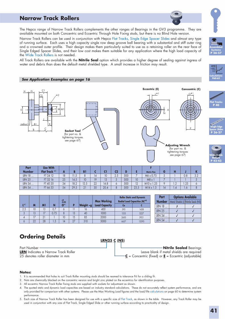
Narrow Track Rollers
41
Notes:1. It is recommended that holes to suit Track Roller mounting studs should be reamed to tolerance F6 for a sliding fit.2. Nuts are chemically blacked on the concentric version and bright zinc plated on the eccentrics for identification purposes. 3. All eccentric Narrow Track Roller fixing studs are supplied with sockets for adjustment as shown.4. The quoted static and dynamic load capacities are based on industry standard calculations. These do not accurately reflect system performance, and are
only provided for comparison with other systems. Please use the Max Working Load figures and the load/life calculations on page 60 to determine system performance.
5. Each size of Narrow Track Roller has been designed for use with a specific size of Flat Track, as shown in the table. However, any Track Roller may be used in conjunction with any size of Flat Track, Single Edged Slide or other running surface according to practicality of design.
H G
E
C1
C2
radius D B1
B
J
K
C
F M M1
NA
O*1L*3
P
Eccentric (E) Concentric (C)
A18253454
K3.2568
B1810
12.521
C11013
14.820.4
C22.5568
B11.514.518.229.5
C14192230
D500500500500
E71012
23.5
FMetric Fine
M6 x 0.75M8 x 1
M10 x 1.25M14 x 1.5
G57914
H11
1.21.4
J0.81
1.251.6
PartNumberLRN 18 ...LRN 25 ...LRN 34 ...LRN 54 ...
Use WithFlat Track *5
FT 24 12FT 32 16FT 40 20FT 66 33
L*3
2.5346
M10131722
M113172128
N0.7
0.751
1.5
Co
593
1333
2600
6657
O*1
681014
P11131527
Weight ~g164085310
Max WorkingLoad Capacity
400100020005000
Roller Static and DynamicRadial Load Capacities (N)*4
C
1438
3227
5921
13595
+0-0.03
The Hepco range of Narrow Track Rollers complements the other ranges of Bearings in the GV3 programme. They are available mounted on both Concentric and Eccentric Through Hole Fixing studs, but there is no Blind Hole version.Narrow Track Rollers can be used in conjunction with Hepco Flat Tracks, Single Edge Spacer Slides and almost any type of running surface. Each uses a high capacity single row deep groove ball bearing with a substantial and stiff outer ring and a crowned outer profile. Their design makes them particularly suited to use as a retaining roller on the rear face of Single Edged Spacer Slides, and their low cost makes them suitable for any application where the high load capacity of the Wide Track Rollers is not needed.All Track Rollers are available with the Nitrile Seal option which provides a higher degree of sealing against ingress of water and debris than does the default metal shielded type. A small increase in friction may result.
Ordering Details
Part NumberLRN Indicates a Narrow Track Roller25 denotes roller diameter in mm
Nitrile Sealed BearingsLeave blank if metal shields are required
C = Concentric (fixed) or E = Eccentric (adjustable)
Adjusting Wrench(for part no. &
tightening torquessee page 67)
Socket Tool(for part no. &
tightening torquessee page 67)
See Application Examples on page 16
PartNumberLRN 18 ...LRN 25 ...LRN 34 ...LRN 54 ...
Metal Shields (-) Nitrile Seals (NS)Options Available
✓
✓
✓
✓
✗
✓
✓
✓
Flat TracksP 40
*2
Wide Track Rollers
P 42-43
CalculationsP60-62
XYZ+ABC
123
LRN25 C (NS)
AssembledSystemsP 56-57
Single Edge Spacer SlidesP 26-27
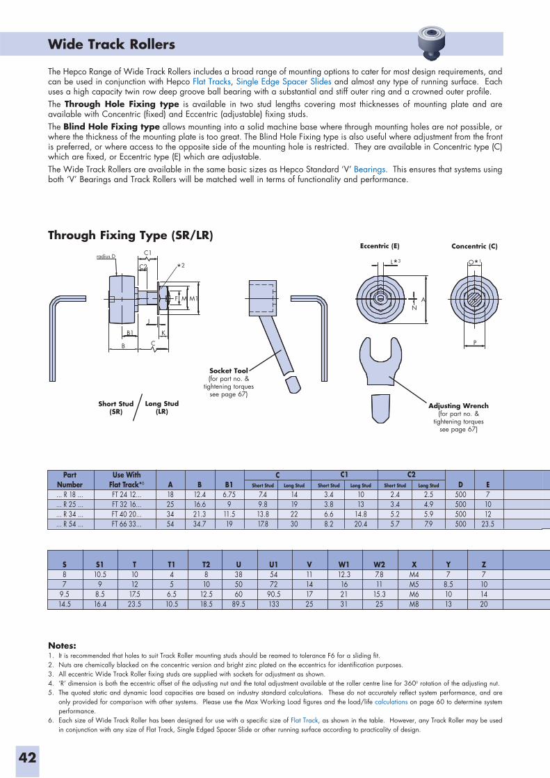
Wide Track Rollers
42
Notes:1. It is recommended that holes to suit Track Roller mounting studs should be reamed to tolerance F6 for a sliding fit.2. Nuts are chemically blacked on the concentric version and bright zinc plated on the eccentrics for identification purposes. 3. All eccentric Wide Track Roller fixing studs are supplied with sockets for adjustment as shown.4. ‘R’ dimension is both the eccentric offset of the adjusting nut and the total adjustment available at the roller centre line for 3600 rotation of the adjusting nut.5. The quoted static and dynamic load capacities are based on industry standard calculations. These do not accurately reflect system performance, and are
only provided for comparison with other systems. Please use the Max Working Load figures and the load/life calculations on page 60 to determine system performance.
6. Each size of Wide Track Roller has been designed for use with a specific size of Flat Track, as shown in the table. However, any Track Roller may be used in conjunction with any size of Flat Track, Single Edged Spacer Slide or other running surface according to practicality of design.
radius D C1
C2
B1
B
J
C
K
F M M1
L*3 O*1
N
P
A
Through Fixing Type (SR/LR) Eccentric (E) Concentric (C)
Short Stud(SR)
Long Stud(LR)
PartNumber... R 18 ...... R 25 ...... R 34 ...... R 54 ...
Use WithFlat Track*6
FT 24 12...FT 32 16...FT 40 20...FT 66 33...
A18253454
B12.416.621.334.7
B16.75
911.519
C C1 C2Short Stud
7.49.813.817.8
Long Stud
14192230
Short Stud
3.43.86.68.2
Long Stud
1013
14.820.4
Short Stud
2.43.45.25.7
Long Stud
2.54.95.97.9
D500500500500
E71012
23.5
The Hepco Range of Wide Track Rollers includes a broad range of mounting options to cater for most design requirements, and can be used in conjunction with Hepco Flat Tracks, Single Edge Spacer Slides and almost any type of running surface. Each uses a high capacity twin row deep groove ball bearing with a substantial and stiff outer ring and a crowned outer profile. The Through Hole Fixing type is available in two stud lengths covering most thicknesses of mounting plate and are available with Concentric (fixed) and Eccentric (adjustable) fixing studs.The Blind Hole Fixing type allows mounting into a solid machine base where through mounting holes are not possible, or where the thickness of the mounting plate is too great. The Blind Hole Fixing type is also useful where adjustment from the front is preferred, or where access to the opposite side of the mounting hole is restricted. They are available in Concentric type (C) which are fixed, or Eccentric type (E) which are adjustable. The Wide Track Rollers are available in the same basic sizes as Hepco Standard ‘V’ Bearings. This ensures that systems using both ‘V’ Bearings and Track Rollers will be matched well in terms of functionality and performance.
Adjusting Wrench(for part no. &
tightening torquessee page 67)
Socket Tool(for part no. &
tightening torquessee page 67)
S87
9.514.5
S110.5
98.516.4
T1012
17.523.5
T145
6.510.5
Y7
8.51013
Z7101420
T2810
12.518.5
U385060
89.5
U15472
90.5133
W112.3162131
V11141725
W27.811
15.325
XM4M5M6M8
*2
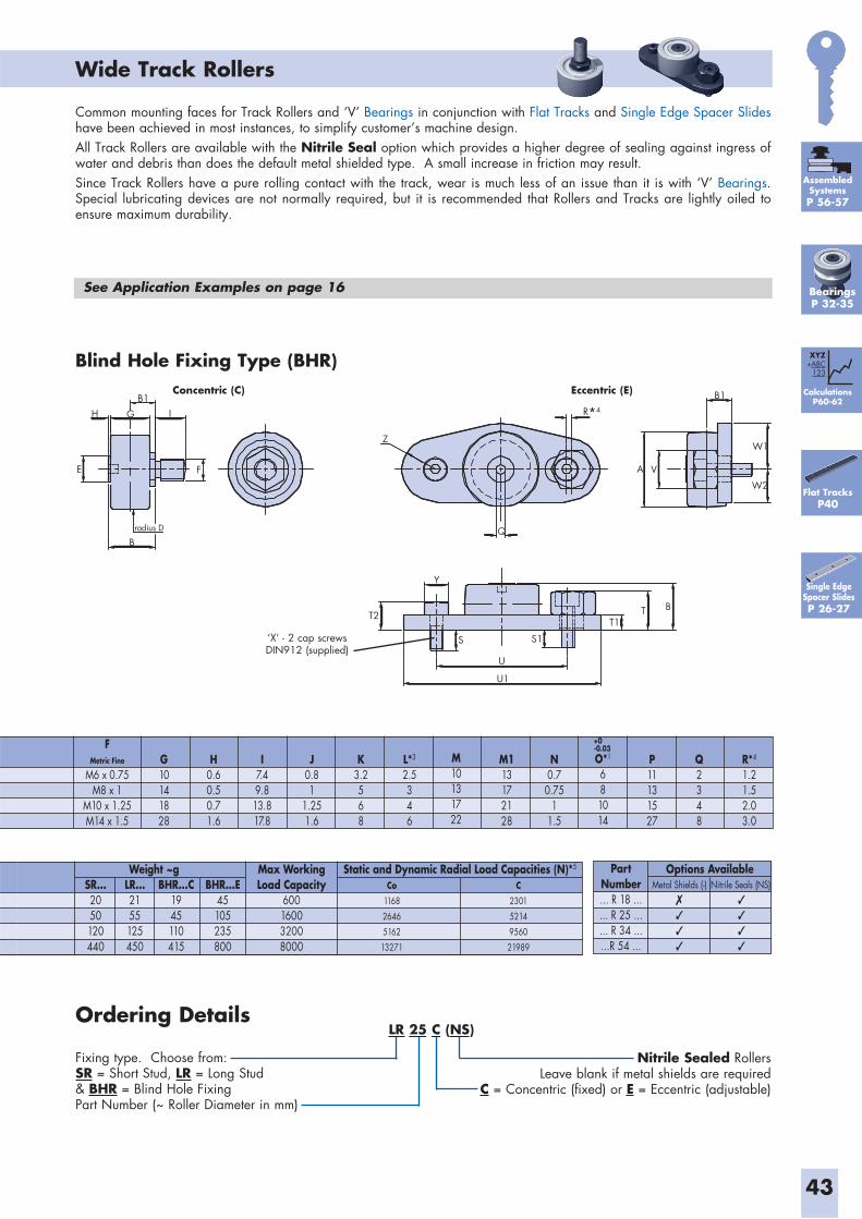
Wide Track Rollers
Common mounting faces for Track Rollers and ‘V’ Bearings in conjunction with Flat Tracks and Single Edge Spacer Slides have been achieved in most instances, to simplify customer’s machine design.All Track Rollers are available with the Nitrile Seal option which provides a higher degree of sealing against ingress of water and debris than does the default metal shielded type. A small increase in friction may result.Since Track Rollers have a pure rolling contact with the track, wear is much less of an issue than it is with ‘V’ Bearings. Special lubricating devices are not normally required, but it is recommended that Rollers and Tracks are lightly oiled to ensure maximum durability.
Ordering Details
Fixing type. Choose from:SR = Short Stud, LR = Long Stud & BHR = Blind Hole FixingPart Number (~ Roller Diameter in mm)
Nitrile Sealed RollersLeave blank if metal shields are required
C = Concentric (fixed) or E = Eccentric (adjustable)
43
HB1
G I
F
Bradius D
Z
Q
R*4
A V
B1
W1
W2
T2
Y
S
U
U1
S1
T1T B
E
Blind Hole Fixing Type (BHR) Eccentric (E)
‘X’ - 2 cap screws DIN912 (supplied)
Concentric (C)
Weight ~gSR...2050120440
LR...2155125450
BHR...C1945110415
BHR...E45105235800
Max WorkingLoad Capacity
600160032008000
Static and Dynamic Radial Load Capacities (N)*5
Co
1168
2646
5162
13271
C
2301
5214
9560
21989
See Application Examples on page 16
PartNumber... R 18 ...... R 25 ...... R 34 ......R 54 ...
Metal Shields (-) Nitrile Seals (NS)Options Available
�
�
�
�
�
�
�
�
FMetric Fine
M6 x 0.75M8 x 1
M10 x 1.25M14 x 1.5
G10141828
H0.60.50.71.6
I7.49.813.817.8
J0.81
1.251.6
K3.2568
L*3
2.5346
M10131722
M113172128
N0.7
0.751
1.5
P11131527
O*1
681014
Q2348
R*4
1.21.52.03.0
+0-0.03
LR 25 C (NS)
Flat TracksP40
CalculationsP60-62
XYZ+ABC
123
AssembledSystemsP 56-57
BearingsP 32-35
Single Edge Spacer SlidesP 26-27
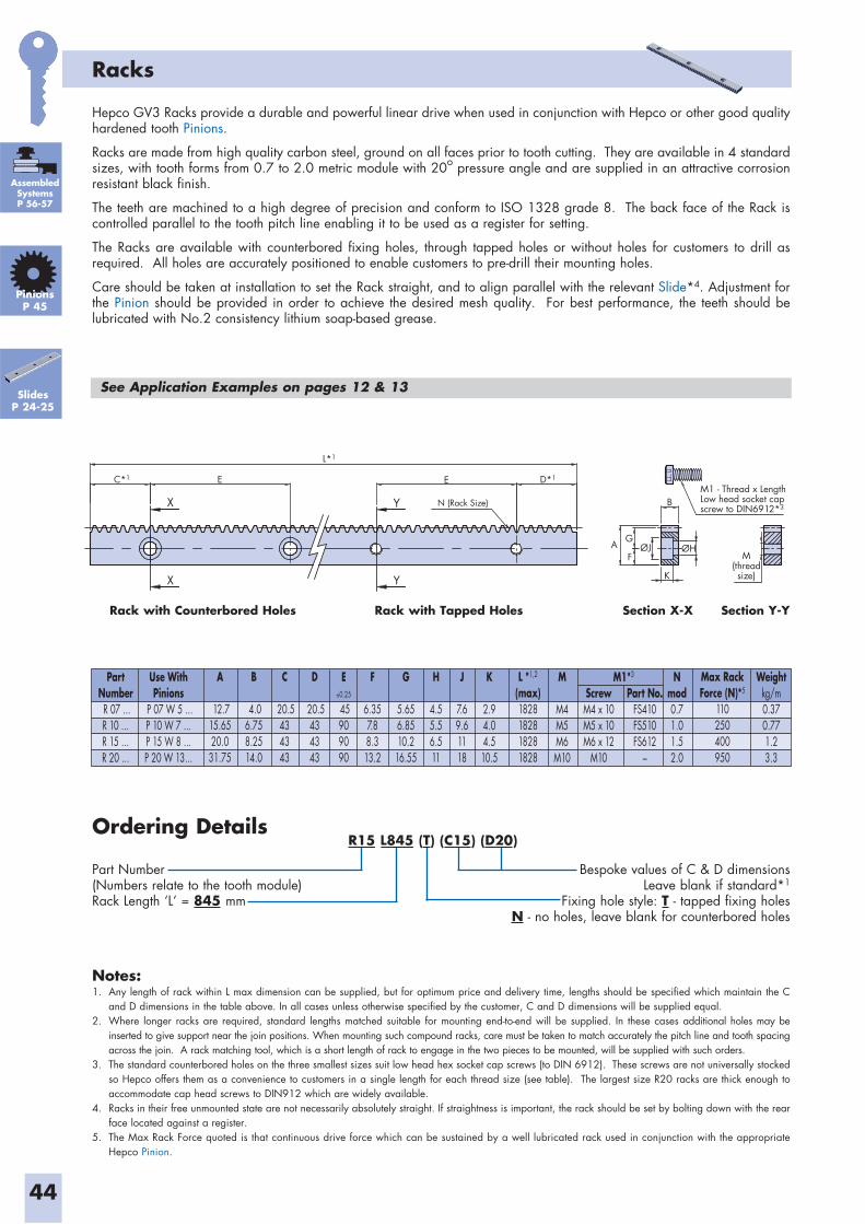
44
C*1 D*1
L*1
M1 - Thread x LengthLow head socket capscrew to DIN6912*3
E
A
B
G
F
K
M(threadsize)
ØJ ØH
N (Rack Size)
E
X
X Y
Y
PartNumber R 07 ...R 10 ...R 15 ...R 20 ...
Use WithPinions
P 07 W 5 ...P 10 W 7 ...P 15 W 8 ...P 20 W 13...
A
12.715.6520.0
31.75
B
4.06.758.2514.0
C
20.5434343
D
20.5434343
F
6.357.88.313.2
G
5.656.8510.2
16.55
H
4.55.56.511
J
7.69.61118
K
2.94.04.510.5
M
M4M5M6M10
Nmod0.71.01.52.0
E0.25
45909090
L *1,2
(max)1828182818281828
Max RackForce (N)*5
110250400950
Weightkg/m0.370.771.23.3
ScrewM4 x 10M5 x 10M6 x 12
M10
Part No.FS410FS510FS612
–
M1*3
Part Number(Numbers relate to the tooth module)Rack Length ‘L’ = 845 mm
Bespoke values of C & D dimensionsLeave blank if standard*1
Fixing hole style: T - tapped fixing holesN - no holes, leave blank for counterbored holes
Ordering Details
Notes:1. Any length of rack within L max dimension can be supplied, but for optimum price and delivery time, lengths should be specified which maintain the C
and D dimensions in the table above. In all cases unless otherwise specified by the customer, C and D dimensions will be supplied equal. 2. Where longer racks are required, standard lengths matched suitable for mounting end-to-end will be supplied. In these cases additional holes may be
inserted to give support near the join positions. When mounting such compound racks, care must be taken to match accurately the pitch line and tooth spacing across the join. A rack matching tool, which is a short length of rack to engage in the two pieces to be mounted, will be supplied with such orders.
3. The standard counterbored holes on the three smallest sizes suit low head hex socket cap screws (to DIN 6912). These screws are not universally stocked so Hepco offers them as a convenience to customers in a single length for each thread size (see table). The largest size R20 racks are thick enough to accommodate cap head screws to DIN912 which are widely available.
4. Racks in their free unmounted state are not necessarily absolutely straight. If straightness is important, the rack should be set by bolting down with the rear face located against a register.
5. The Max Rack Force quoted is that continuous drive force which can be sustained by a well lubricated rack used in conjunction with the appropriate Hepco Pinion.
Racks
Hepco GV3 Racks provide a durable and powerful linear drive when used in conjunction with Hepco or other good quality hardened tooth Pinions.
Racks are made from high quality carbon steel, ground on all faces prior to tooth cutting. They are available in 4 standard sizes, with tooth forms from 0.7 to 2.0 metric module with 20o pressure angle and are supplied in an attractive corrosion resistant black finish.
The teeth are machined to a high degree of precision and conform to ISO 1328 grade 8. The back face of the Rack is controlled parallel to the tooth pitch line enabling it to be used as a register for setting.
The Racks are available with counterbored fixing holes, through tapped holes or without holes for customers to drill as required. All holes are accurately positioned to enable customers to pre-drill their mounting holes.
Care should be taken at installation to set the Rack straight, and to align parallel with the relevant Slide*4. Adjustment for the Pinion should be provided in order to achieve the desired mesh quality. For best performance, the teeth should be lubricated with No.2 consistency lithium soap-based grease.
See Application Examples on pages 12 & 13
PinionsP 45
SlidesP 24-25
Rack with Counterbored Holes Rack with Tapped Holes Section Y-YSection X-X
R15 L845 (T) (C15) (D20)
AssembledSystemsP 56-57
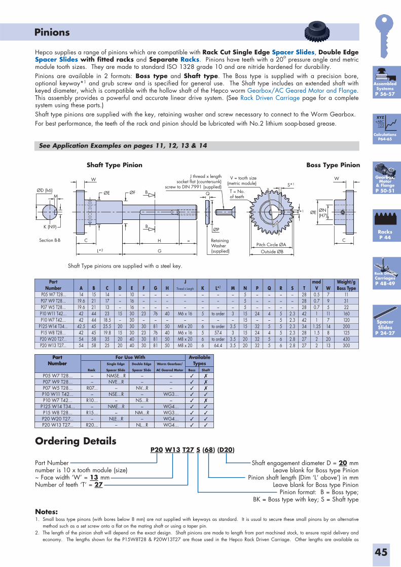
45
Pinions
Ordering Details
Part Numbernumber is 10 x tooth module (size)~ Face width ‘W’ = 13 mmNumber of teeth ‘T’ = 27
Shaft engagement diameter D = 20 mmLeave blank for Boss type Pinion
Pinion shaft length (Dim ‘L’ above’) in mmLeave blank for Boss type Pinion
Pinion format: B = Boss type; BK = Boss type with key; S = Shaft type
PartNumber
P05 W7 T28...P07 W9 T28...P07 W5 T28...P10 W11 T42...P10 W7 T42...
P125 W14 T34...P15 W8 T28...P20 W20 T27...P20 W13 T27...
J modA14
19.619.64242
42.5425454
B152121444445455858
C14171323
18.525.519.83525
D–––
15–
20152020
E101616303030304040
F–––
23–
30233030
G–––
76–
81768181
H–––
40–
50405050
M–––3–
3.53
3.53.5
N555151515152020
K–––5–6566
P–––
24–
32243232
Q–––4–5455
R–––555566
S–––
2.32.32.32.32.82.8
T282828424234282727
V0.50.70.711
1.251.522
Weight/gBoss Type
113122160120200125430300
W795117148
2013
L*2
–––
to order–
to order57.4
to order64.4
Thread x Length
–––
M6 x 16–
M8 x 20M6 x 16M8 x 20M8 x 20
Hepco supplies a range of pinions which are compatible with Rack Cut Single Edge Spacer Slides, Double Edge Spacer Slides with fitted racks and Separate Racks. Pinions have teeth with a 20o pressure angle and metric module tooth sizes. They are made to standard ISO 1328 grade 10 and are nitride hardened for durability.Pinions are available in 2 formats: Boss type and Shaft type. The Boss type is supplied with a precision bore, optional keyway*1 and grub screw and is specified for general use. The Shaft type includes an extended shaft with keyed diameter, which is compatible with the hollow shaft of the Hepco worm Gearbox/AC Geared Motor and Flange. This assembly provides a powerful and accurate linear drive system. (See Rack Driven Carriage page for a complete system using these parts.)Shaft type pinions are supplied with the key, retaining washer and screw necessary to connect to the Worm Gearbox.For best performance, the teeth of the rack and pinion should be lubricated with No.2 lithium soap-based grease.
See Application Examples on pages 11, 12, 13 & 14
Rack DrivenCarriagesP 48-49
RacksP 44
Notes:1. Small boss type pinons (with bores below 8 mm) are not supplied with keyways as standard. It is usual to secure these small pinons by an alternative
method such as a set screw onto a flat on the mating shaft or using a taper pin.2. The length of the pinion shaft will depend on the exact design. Shaft pinions are made to length from part machined stock, to ensure rapid delivery and
economy. The lengths shown for the P15W8T28 & P20W13T27 are those used in the Hepco Rack Driven Carriage. Other lengths are available as
L*2
R*1
S*1
ØD (h6)
Section B-B C H RetainingWasher(supplied)
T = No.of teeth
G
=
B
B QM
K (N9)
WJ thread x length
socket flat (countersunk)screw to DIN 7991 (supplied)
V = tooth size(metric module)
ØE ØF
ØP
ØE
Pitch Circle ØAOutside ØB
ØN(H7)
C
W
Shaft Type Pinion Boss Type Pinion
Shaft Type pinions are supplied with a steel key.
P05 W7 T28...P07 W9 T28...P07 W5 T28...P10 W11 T42...P10 W7 T42...
P125 W14 T34...P15 W8 T28...P20 W20 T27...P20 W13 T27...
PartNumber
PartNumber
For Use With AvailableTypes
–––
R07...–
R10...–
R15...–
R20...
Rack Boss Shaft
NMSE...RNVE...R
–NSE...R
–NME...R
–NLE...R
–
Single Edge
Spacer Slide
––
NV...R–
NS...R–
NM...R–
NL...R
Double Edge
Spacer Slide
–––
WG3...–
WG4...WG3...WG4...WG4...
Worm Gearbox/
AC Geared Motor
CalculationsP64-65
XYZ+ABC
123
Gearbox, Motor
& FlangeP 50-51
Spacer Slides
P 24-27
P20 W13 T27 S (68) (D20)
AssembledSystemsP 56-57
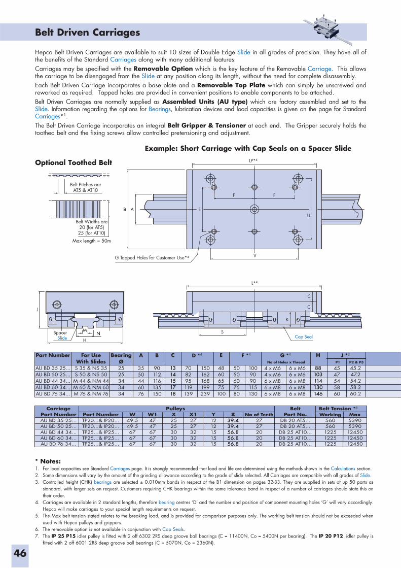
46
Belt Driven Carriages
L*4
LP*4
G Tapped Holes for Customer Use*4
Belt Widths are20 (for AT5)25 (for AT10)
Max length = 50m
Belt Pitches areAT5 & AT10
S
H
SpacerSlide
J
NNM
BBB
F F
UA E
V
K
C
C
Cap Seal
Part Number
AU BD 35 25...AU BD 50 25...AU BD 44 34...AU BD 60 34...AU BD 76 34...
For UseWith SlidesS 35 & NS 35S 50 & NS 50
M 44 & NM 44M 60 & NM 60M 76 & NM 76
BearingØ2525343434
A
3550446076
B
90112116135150
C
1314151718
C
1314151718
E
48606575100
H
88103114130146
708295119139
150162168199239
5050607580
1009090115130
4 x M64 x M66 x M86 x M86 x M8
6 x M66 x M66 x M86 x M86 x M8
4547545860
D *4 F *4 G *4 J *2
No of Holes x Thread P1
45.247.254.258.260.2
P2 & P3
H
88103114130146
* Notes:1. For load capacities see Standard Carriages page. It is strongly recommended that load and life are determined using the methods shown in the Calculations section.2. Some dimensions will vary by the amount of the grinding allowance according to the grade of slide selected. All Carriages are compatible with all grades of Slide.3. Controlled height (CHK) bearings are selected ± 0.010mm bands in respect of the B1 dimension on pages 32-33. They are supplied in sets of up 50 parts as
standard, with larger sets on request. Customers requiring CHK bearings within the same tolerance band in respect of a number of carriages should state this on their order.
4. Carriages are available in 2 standard lengths, therefore bearing centres ‘D’ and the number and position of component mounting holes ‘G’ will vary accordingly. Hepco will make carriages to your special length requirements on request.
5. The Max belt tension stated relates to the breaking load, and is provided for comparison purposes only. The working belt tension should not be exceeded when used with Hepco pulleys and grippers.
6. The removable option is not available in conjunction with Cap Seals.7. The IP 25 P15 idler pulley is fitted with 2 off 6302 2RS deep groove ball bearings (C = 11400N, Co = 5400N per bearing). The IP 20 P12 idler pulley is
fitted with 2 off 6001 2RS deep groove ball bearings (C = 5070N, Co = 2360N).
Example: Short Carriage with Cap Seals on a Spacer Slide
Hepco Belt Driven Carriages are available to suit 10 sizes of Double Edge Slide in all grades of precision. They have all of the benefits of the Standard Carriages along with many additional features: Carriages may be specified with the Removable Option which is the key feature of the Removable Carriage. This allows the carriage to be disengaged from the Slide at any position along its length, without the need for complete disassembly.Each Belt Driven Carriage incorporates a base plate and a Removable Top Plate which can simply be unscrewed and reworked as required. Tapped holes are provided in convenient positions to enable components to be attached.Belt Driven Carriages are normally supplied as Assembled Units (AU type) which are factory assembled and set to the Slide. Information regarding the options for Bearings, lubrication devices and load capacities is given on the page for Standard Carriages*1. The Belt Driven Carriage incorporates an integral Belt Gripper & Tensioner at each end. The Gripper securely holds the toothed belt and the fixing screws allow controlled pretensioning and adjustment.
Optional Toothed Belt
CarriagePart NumberAU BD 35 25...AU BD 50 25...AU BD 44 34...AU BD 60 34...AU BD 76 34...
BeltPart No.
DB 20 AT5...DB 20 AT5...DB 25 AT10...DB 25 AT10...DB 25 AT10...
Pulleys Belt Tension *5
Part NumberTP20...& IP20...TP20...& IP20...TP25...& IP25...TP25...& IP25...TP25...& IP25...
W49.549.5676767
W14747676767
X2525303030
X12727323232
Y1212151515
Z39.439.456.856.856.8
Z39.439.456.856.856.8
No of Teeth2727202020
Working560560122512251225
Max53905390124501245012450
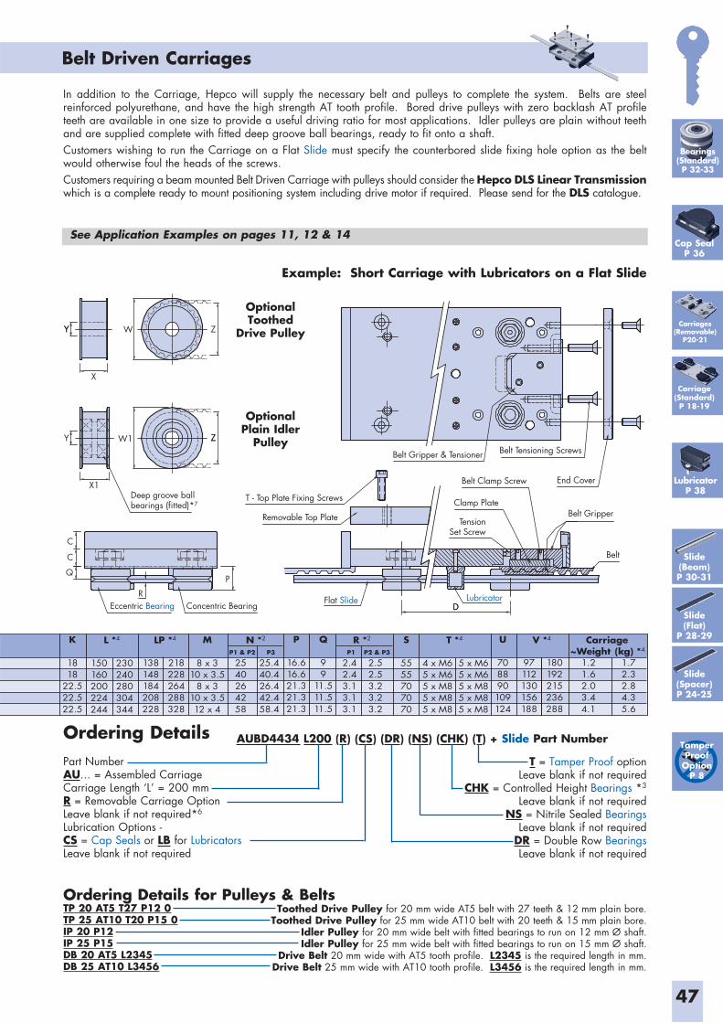
AUBD4434 L200 (R) (CS) (DR) (NS) (CHK) (T) + Slide Part Number
47
Belt Driven Carriages
Deep groove ballbearings (fitted)*7
T - Top Plate Fixing Screws
Removable Top Plate
REccentric Bearing Concentric Bearing
Flat Slide LubricatorDD
TensionSet Screw
Belt
Belt Clamp Screw
Clamp PlateBelt Gripper
End Cover
Belt Tensioning ScrewsBelt Gripper & Tensioner
P
C
X1
Y
YY
X
W
ZZ
Z
W1
C
Q
P
16.616.621.321.321.3
Q
99
11.511.511.5
U
708890109124
97112130156188
180192215236288
1.21.62.03.44.1
1.72.32.84.35.6
M
8 x 310 x 3.5
8 x 310 x 3.512 x 4
4 x M65 x M65 x M85 x M85 x M8
5 x M65 x M65 x M85 x M85 x M8
S
5555707070
150160200224244
230240280304344
L *4
138148184208228
218228264288328
LP *4 N *2 T *4 V *4R *2 Carriage
2540264258
P1 & P2
2.52.53.23.23.2
P2 & P3
2.42.43.13.13.1
P1 ~Weight (kg) *4
25.440.426.442.458.4
P3
K
1818
22.522.522.5
Ordering DetailsPart NumberAU... = Assembled Carriage Carriage Length ‘L’ = 200 mmR = Removable Carriage OptionLeave blank if not required*6
Lubrication Options -CS = Cap Seals or LB for Lubricators Leave blank if not required
T = Tamper Proof option Leave blank if not required
CHK = Controlled Height Bearings *3
Leave blank if not requiredNS = Nitrile Sealed Bearings
Leave blank if not requiredDR = Double Row BearingsLeave blank if not required
Example: Short Carriage with Lubricators on a Flat Slide
In addition to the Carriage, Hepco will supply the necessary belt and pulleys to complete the system. Belts are steel reinforced polyurethane, and have the high strength AT tooth profile. Bored drive pulleys with zero backlash AT profile teeth are available in one size to provide a useful driving ratio for most applications. Idler pulleys are plain without teeth and are supplied complete with fitted deep groove ball bearings, ready to fit onto a shaft.Customers wishing to run the Carriage on a Flat Slide must specify the counterbored slide fixing hole option as the belt would otherwise foul the heads of the screws.Customers requiring a beam mounted Belt Driven Carriage with pulleys should consider the Hepco DLS Linear Transmission which is a complete ready to mount positioning system including drive motor if required. Please send for the DLS catalogue.
Slide(Beam)P 30-31
Tamper Proof
OptionP 8
Slide(Flat)
P 28-29
See Application Examples on pages 11, 12 & 14
OptionalToothed
Drive Pulley
OptionalPlain Idler
Pulley
Ordering Details for Pulleys & BeltsTP 20 AT5 T27 P12 0TP 25 AT10 T20 P15 0IP 20 P12IP 25 P15DB 20 AT5 L2345DB 25 AT10 L3456
Toothed Drive Pulley for 20 mm wide AT5 belt with 27 teeth & 12 mm plain bore.Toothed Drive Pulley for 25 mm wide AT10 belt with 20 teeth & 15 mm plain bore.
Idler Pulley for 20 mm wide belt with fitted bearings to run on 12 mm Ø shaft.Idler Pulley for 25 mm wide belt with fitted bearings to run on 15 mm Ø shaft.
Drive Belt 20 mm wide with AT5 tooth profile. L2345 is the required length in mm. Drive Belt 25 mm wide with AT10 tooth profile. L3456 is the required length in mm.
Carriage(Standard)P 18-19
Carriages(Removable)
P20-21
Cap SealP 36
LubricatorP 38
Slide(Spacer)P 24-25
Bearings(Standard)P 32-33
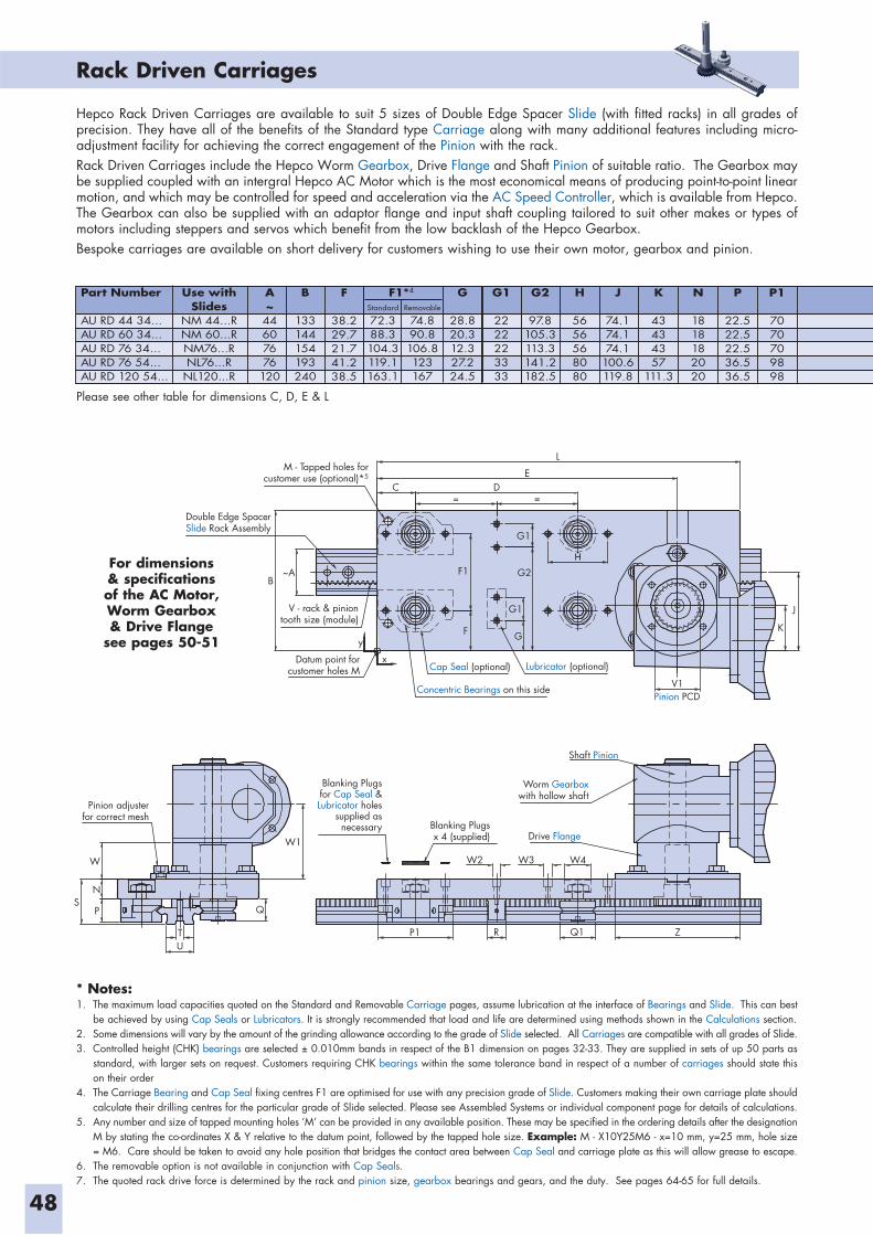
48
* Notes:1. The maximum load capacities quoted on the Standard and Removable Carriage pages, assume lubrication at the interface of Bearings and Slide. This can best
be achieved by using Cap Seals or Lubricators. It is strongly recommended that load and life are determined using methods shown in the Calculations section.2. Some dimensions will vary by the amount of the grinding allowance according to the grade of Slide selected. All Carriages are compatible with all grades of Slide.3. Controlled height (CHK) bearings are selected ± 0.010mm bands in respect of the B1 dimension on pages 32-33. They are supplied in sets of up 50 parts as
standard, with larger sets on request. Customers requiring CHK bearings within the same tolerance band in respect of a number of carriages should state this on their order
4. The Carriage Bearing and Cap Seal fixing centres F1 are optimised for use with any precision grade of Slide. Customers making their own carriage plate should calculate their drilling centres for the particular grade of Slide selected. Please see Assembled Systems or individual component page for details of calculations.
5. Any number and size of tapped mounting holes ‘M’ can be provided in any available position. These may be specified in the ordering details after the designation M by stating the co-ordinates X & Y relative to the datum point, followed by the tapped hole size. Example: M - X10Y25M6 - x=10 mm, y=25 mm, hole size = M6. Care should be taken to avoid any hole position that bridges the contact area between Cap Seal and carriage plate as this will allow grease to escape.
6. The removable option is not available in conjunction with Cap Seals.7. The quoted rack drive force is determined by the rack and pinion size, gearbox bearings and gears, and the duty. See pages 64-65 for full details.
Rack Driven Carriages
Hepco Rack Driven Carriages are available to suit 5 sizes of Double Edge Spacer Slide (with fitted racks) in all grades of precision. They have all of the benefits of the Standard type Carriage along with many additional features including micro-adjustment facility for achieving the correct engagement of the Pinion with the rack. Rack Driven Carriages include the Hepco Worm Gearbox, Drive Flange and Shaft Pinion of suitable ratio. The Gearbox may be supplied coupled with an intergral Hepco AC Motor which is the most economical means of producing point-to-point linear motion, and which may be controlled for speed and acceleration via the AC Speed Controller, which is available from Hepco. The Gearbox can also be supplied with an adaptor flange and input shaft coupling tailored to suit other makes or types of motors including steppers and servos which benefit from the low backlash of the Hepco Gearbox. Bespoke carriages are available on short delivery for customers wishing to use their own motor, gearbox and pinion.
M - Tapped holes forcustomer use (optional)*5
V - rack & piniontooth size (module)
Double Edge SpacerSlide Rack Assembly
B~A
Datum point forcustomer holes M Cap Seal (optional)
Concentric Bearings on this side
Lubricator (optional)x
F G
G1
G2
G1
DE
L
V1
K
J
Pinion PCD
Shaft Pinion
Worm Gearboxwith hollow shaft
Drive Flange
W2
W1
W
SN
P Q
UT P1 R Q1 Z
Pinion adjusterfor correct mesh
Blanking Plugsfor Cap Seal &Lubricator holes
supplied asnecessary
W3 W4
Blanking Plugsx 4 (supplied)
F1
C= =
y
Part Number
AU RD 44 34...AU RD 60 34...AU RD 76 34...AU RD 76 54...AU RD 120 54...
Use withSlides
NM 44...RNM 60...RNM76...RNL76...R
NL120...R
Standard
72.388.3104.3119.1163.1
Removable
74.890.8106.8123167
F1*4A~44607676
120
B
133144154193240
G
28.820.312.327.224.5
G1
2222223333
G2
97.8105.3113.3141.2182.5
H
5656568080
J
74.174.174.1
100.6119.8
K
43434357
111.3
N
1818182020
P
22.522.522.536.536.5
P1
7070709898
F
38.229.721.741.238.5
Please see other table for dimensions C, D, E & L
For dimensions & specifications of the AC Motor, Worm Gearbox & Drive Flange
see pages 50-51
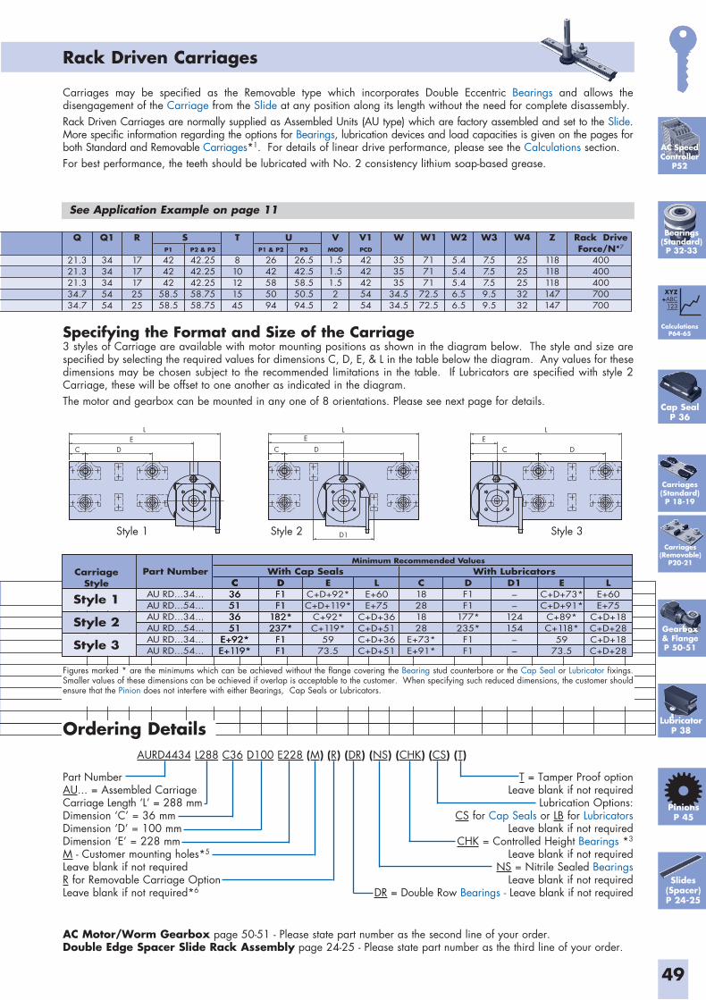
AURD4434 L288 C36 D100 E228 (M) (R) (DR) (NS) (CHK) (CS) (T)
49
Rack Driven Carriages
Ordering Details
Carriages may be specified as the Removable type which incorporates Double Eccentric Bearings and allows the disengagement of the Carriage from the Slide at any position along its length without the need for complete disassembly.Rack Driven Carriages are normally supplied as Assembled Units (AU type) which are factory assembled and set to the Slide. More specific information regarding the options for Bearings, lubrication devices and load capacities is given on the pages for both Standard and Removable Carriages*1. For details of linear drive performance, please see the Calculations section.For best performance, the teeth should be lubricated with No. 2 consistency lithium soap-based grease.
See Application Example on page 11
Gearbox& FlangeP 50-51
Part NumberAU... = Assembled Carriage Carriage Length ‘L’ = 288 mmDimension ‘C’ = 36 mmDimension ‘D’ = 100 mmDimension ‘E’ = 228 mmM - Customer mounting holes*5
Leave blank if not requiredR for Removable Carriage OptionLeave blank if not required*6
T = Tamper Proof option Leave blank if not required
Lubrication Options:CS for Cap Seals or LB for Lubricators
Leave blank if not requiredCHK = Controlled Height Bearings *3
Leave blank if not requiredNS = Nitrile Sealed Bearings
Leave blank if not requiredDR = Double Row Bearings - Leave blank if not required
L
C D
E EC D
LL
D1
EDC
Q
21.321.321.334.734.7
Q1
3434345454
R
1717172525
UT
810121545
VMOD
1.51.51.522
Rack DriveForce/N*7
400400400700700
W1
717171
72.572.5
W
353535
34.534.5
V1PCD
4242425454
W2
5.45.45.46.56.5
Z
118118118147147
W4
2525253232
W3
7.57.57.59.59.5
SP1
424242
58.558.5
P1 & P2
2642585094
P2 & P3
42.2542.2542.2558.7558.75
P3
26.542.558.550.594.5
Specifying the Format and Size of the Carriage3 styles of Carriage are available with motor mounting positions as shown in the diagram below. The style and size are specified by selecting the required values for dimensions C, D, E, & L in the table below the diagram. Any values for these dimensions may be chosen subject to the recommended limitations in the table. If Lubricators are specified with style 2 Carriage, these will be offset to one another as indicated in the diagram.The motor and gearbox can be mounted in any one of 8 orientations. Please see next page for details.
Style 1 Style 3Style 2
C36513651
E+92*
C36513651
E+92*E+119*
C36513651
E+92*E+119*
C18281828
E+73*E+91*
DF1F1
177*235*
F1F1
D1––
124154
––
DF1F1
182*237*
F1F1
DF1F1
182*237*
F1F1
EC+D+92*C+D+119*
C+92*C+119*
5973.5
EC+D+73*C+D+91*
C+89*C+118*
5973.5
LE+60E+75
C+D+18C+D+28C+D+18C+D+28
LE+60E+75
C+D+36C+D+51C+D+36C+D+51
CarriageStyle
Style 1
Style 2
Style 3
Part Number
AU RD...34...AU RD...54...AU RD...34...AU RD...54...AU RD...34...AU RD...54...
With Cap Seals With LubricatorsMinimum Recommended Values
Figures marked * are the minimums which can be achieved without the flange covering the Bearing stud counterbore or the Cap Seal or Lubricator fixings. Smaller values of these dimensions can be achieved if overlap is acceptable to the customer. When specifying such reduced dimensions, the customer should ensure that the Pinion does not interfere with either Bearings, Cap Seals or Lubricators.
AC Motor/Worm Gearbox page 50-51 - Please state part number as the second line of your order.Double Edge Spacer Slide Rack Assembly page 24-25 - Please state part number as the third line of your order.
AC Speed Controller
P52
CalculationsP64-65
XYZ+ABC
123
PinionsP 45
Slides (Spacer)P 24-25
Carriages(Removable)
P20-21
Carriages(Standard)P 18-19
Bearings(Standard)P 32-33
Cap SealP 36
LubricatorP 38
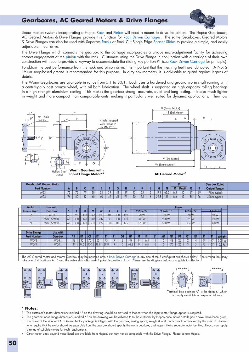
50
* Notes:1. The customer’s motor dimensions marked *1 on the drawing should be advised to Hepco when the input motor flange option is required.2. The gearbox input flange dimensions marked *2 on the drawing will be advised to to the customer by Hepco once motor details (see above) have been given.3. The motor of the standard AC Geared Motor package is integral with the gearbox, saving space, weight & cost, and cannot be removed by the user. Customers
who require that the motor should be separable from the gearbox should specify the worm gearbox, and request that a separate motor be fitted. Hepco can supply a range of suitable motors for such requirements.
4. Other motor sizes beyond those listed are available from Hepco, but may not be compatible with the Drive Flange. Please consult Hepco.
Gearboxes, AC Geared Motors & Drive Flanges
U (Brake Motor)T (Std Motor)
HS
V (Std Motor)
W (Brake Motor)F G
X
4 holes tappedwith thread Pon ØN PCD
Hollow ShaftDetail
k*1 a*2
h*1 j*1 b*2
g*1
c*2
e*1 f*1
d*1
m*1 holedetails H
90
L
K
J
M F G
Worm Gearbox withInput Flange Motor*3 AC Geared Motor*3
MotorFrame Size*4
566371
Use withGearbox
WG3WG3 & WG4WG3 & WG4
S606565
T90100100
U130140140
V167187212
W210247272
X111123138
Y100100110
Z109113125
2 Pole ‘S’90 W180 W370 W
2 Pole ‘L’120 W250 W550 W
4 Pole ‘S’60 W120 W250 W
4 Pole ‘L’90 W180 W370 W
Power
Drive FlangePart Number
WGF3WGF4
Use withGearboxWG3...WG4...
B135
34.5
A1118147
C175100
D163
88.8
E175
88.8
F199
G125
H149
62.8
J11417
K1M5M6
L156
M166
N14870
P12025
Q123
R145
Weight0.34 kg0.5 kg
S15776
T14357
111 2 3 4 5 67
8 2
2
C
D
B
A
22 3 4
3 4
3 4
1
111
The AC Geared Motor and Worm Gearbox may be mounted onto a Rack Driven Carriage in any one of the 8 configurations shown below. The terminal box may take one of 4 positions A...D and the cable exits also have 4 possible positions 1...4. Please use the diagram below as a guide to selection.
Terminal box position A1 is the default, which is usually available on express delivery.
Gearbox/AC Geared MotorPart Number
WG3WG4
A7276
B7580
C7782
D3848
E3340
F3949
G4151
H5771
J1520
K2535
L56
M17.322.8
N62.585
ØM5M6
Depth1012
P Gearbox RatedOutput Torque17Nm (typical)32Nm (typical)
Q6785
R6976
Linear motion systems incorporating a Hepco Rack and Pinion will need a means to drive the pinion. The Hepco Gearboxes, AC Geared Motors & Drive Flanges provide this function for Rack Driven Carriages. The same Gearboxes, Geared Motors & Drive Flanges can also be used with Separate Racks or Rack Cut Single Edge Spacer Slides to provide a simple, and easily adjustable linear drive.The Drive Flange which connects the gearbox to the carriage incorporates a unique micro-adjustment facility for achieving correct engagement of the pinion with the rack. Customers using the Drive Flange in conjunction with a carriage of their own construction will need to provide a keyway to accommodate the sliding key portion P1 (see Rack Driven Carriage for principle).To obtain the best performance from the rack and pinion drive, it is important that the meshing teeth are lubricated. A No. 2 lithium soap-based grease is recommended for this purpose. In dirty environments, it is advisable to guard against ingress of debris.The Worm Gearboxes are available in ratios from 5:1 to 80:1. Each uses a hardened and ground worm shaft running with a centrifugally cast bronze wheel, with oil bath lubrication. The wheel shaft is supported on high capacity rolling bearings in a high strength aluminium casting. This makes the gearbox strong, accurate, quiet and long lasting. It is also much lighter in weight and more compact than comparable units, making it particularly well suited for dynamic applications. Their low
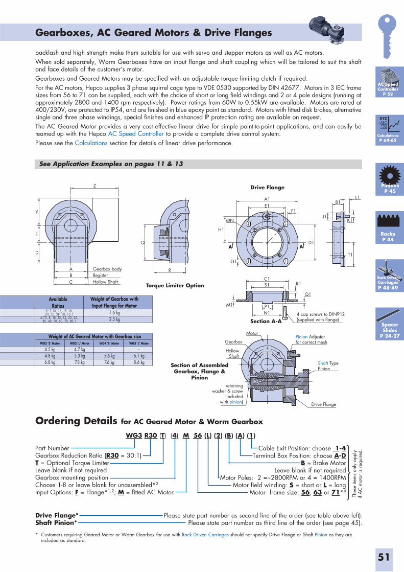
WG3 R30 (T) (4) M 56 (L) (2) (B) (A) (1)
51
Gearboxes, AC Geared Motors & Drive Flanges
Ordering Details for AC Geared Motor & Worm Gearbox
backlash and high strength make them suitable for use with servo and stepper motors as well as AC motors.When sold separately, Worm Gearboxes have an input flange and shaft coupling which will be tailored to suit the shaft and face details of the customer’s motor.Gearboxes and Geared Motors may be specified with an adjustable torque limiting clutch if required.For the AC motors, Hepco supplies 3 phase squirrel cage type to VDE 0530 supported by DIN 42677. Motors in 3 IEC frame sizes from 56 to 71 can be supplied, each with the choice of short or long field windings and 2 or 4 pole designs (running at approximately 2800 and 1400 rpm respectively). Power ratings from 60W to 0.55kW are available. Motors are rated at 400/230V, are protected to IP54, and are finished in blue epoxy paint as standard. Motors with fitted disk brakes, alternative single and three phase windings, special finishes and enhanced IP protection rating are available on request.The AC Geared Motor provides a very cost effective linear drive for simple point-to-point applications, and can easily be teamed up with the Hepco AC Speed Controller to provide a complete drive control system.Please see the Calculations section for details of linear drive performance.
Rack DrivenCarriagesP 48-49
Part NumberGearbox Reduction Ratio (R30 = 30:1) T = Optional Torque LimiterLeave blank if not requiredGearbox mounting positionChoose 1-8 or leave blank for unassembled*2
Input Options: F = Flange*1,2; M = fitted AC Motor
Cable Exit Position: choose 1-4Terminal Box Position: choose A-D
B = Brake MotorLeave blank if not required
Motor Poles: 2 =~2800RPM or 4 = 1400RPM Motor field winding: S = short or L = long
Motor frame size: 56, 63 or 71*4
A A
H1
ØN
G1
D1
B1L1
J1K1
T1
C1S1
P1N1
M1
R1
Q1
4 cap screws to DIN912(supplied with flange)Section A-A
Motor
GearboxPinion Adjusterfor correct mesh
Shaft TypePinion
Drive Flange
HollowShaft
retainingwasher & screw
(includedwith pinion)
Section of AssembledGearbox, Flange &
Pinion
Z
Y
E
D
C
AB
Hollow Shaft
Gearbox bodyRegister
Q
R
Torque Limiter Option
Drive Flange
A1E1
F1
Thes
e ite
ms
only
app
ly
if A
C m
otor
is r
equi
red.
WG3 ‘S’ Motor
4.5 kg4.8 kg6.8 kg
WG3 ‘L’ Motor
4.7 kg5.3 kg7.8 kg
WG4 ‘S’ Motor
–5.6 kg7.6 kg
WG3 ‘L’ Motor
–6.1 kg8.6 kg
Weight of AC Geared Motor with Gearbox size
See Application Examples on pages 11 & 13
AC SpeedController
P 52
Drive Flange* Please state part number as second line of the order (see table above left).Shaft Pinion* Please state part number as third line of the order (see page 45).
* Customers requiring Geared Motor or Worm Gearbox for use with Rack Driven Carriages should not specify Drive Flange or Shaft Pinion as they are included as standard.
AvailableRatios
Weight of Gearbox withInput Flange for Motor
1.6 kg2.5 kg
5, 7, 10, 12, 15, 18,24, 30, 38, 50, 75:1
6.75, 8, 10, 12, 15, 20, 25,30, 40, 50, 60, 70, 80:1
CalculationsP 64-65
XYZ+ABC
123
RacksP 44
PinionsP 45
Spacer Slides
P 24-27
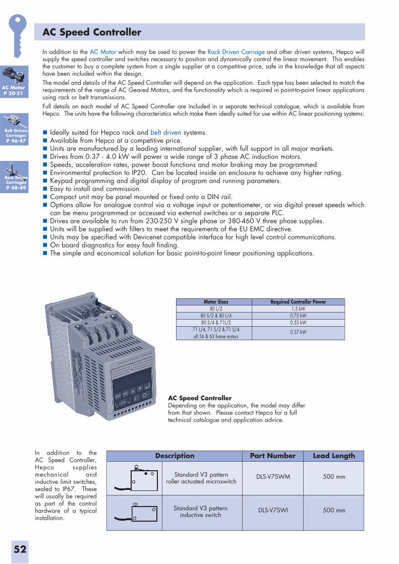
52
AC Speed Controller
In addition to the AC Motor which may be used to power the Rack Driven Carriage and other driven systems, Hepco will supply the speed controller and switches necessary to position and dynamically control the linear movement. This enables the customer to buy a complete system from a single supplier at a competitive price, safe in the knowledge that all aspects have been included within the design.The model and details of the AC Speed Controller will depend on the application. Each type has been selected to match the requirements of the range of AC Geared Motors, and the functionality which is required in point-to-point linear applications using rack or belt transmissions.Full details on each model of AC Speed Controller are included in a separate technical catalogue, which is available from Hepco. The units have the following characteristics which make them ideally suited for use within AC linear positioning systems:
Ideally suited for Hepco rack and belt driven systems. Available from Hepco at a competitive price. Units are manufactured by a leading international supplier, with full support in all major markets. Drives from 0.37 - 4.0 kW will power a wide range of 3 phase AC induction motors. Speeds, acceleration rates, power boost functions and motor braking may be programmed. Environmental protection to IP20. Can be located inside an enclosure to achieve any higher rating. Keypad programming and digital display of program and running parameters. Easy to install and commission. Compact unit may be panel mounted or fixed onto a DIN rail. Options allow for analogue control via a voltage input or potentiometer, or via digital preset speeds which can be menu programmed or accessed via external switches or a separate PLC.
Drives are available to run from 230-250 V single phase or 380-460 V three phase supplies. Units will be supplied with filters to meet the requirements of the EU EMC directive. Units may be specified with Devicenet compatible interface for high level control communications. On board diagnostics for easy fault finding. The simple and economical solution for basic point-to-point linear positioning applications.
AC MotorP 50-51
Motor Sizes80 L/2
80 S/2 & 80 L/480 S/4 & 71L/2
71 L/4, 71 S/2 & 71 S/4all 56 & 63 frame motors
Required Controller Power1.5 kW0.75 kW0.55 kW
0.37 kW
AC Speed ControllerDepending on the application, the model may differ from that shown. Please contact Hepco for a full technical catalogue and application advice.
In addition to the AC Speed Controller, Hepco supplies mechanical and inductive limit switches, sealed to IP67. These will usually be required as part of the control hardware of a typical installation.
Standard V3 patternroller actuated microswitch
DLS-V7SWM 500 mm
Standard V3 patterninductive switch
DLS-V7SWI 500 mm
Description Part Number Lead Length
Belt DrivenCarriagesP 46-47
Rack DrivenCarriagesP 48-49
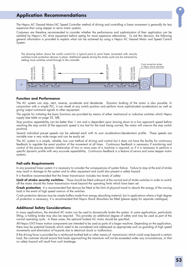
53
Application Recommendations
Function and PerformanceThe AC system can stop, start, reverse, accelerate and decelerate. Dynamic braking of the motor is also possible. In conjunction with a simple PLC, it can dwell at any switch position and perform more sophisticated accelerations as well as giving output command signals to other equipment. The signals for initiating the basic functions are provided by means of either mechanical or inductive switches which Hepco supply (see table on page 52, left). Stop position repeatability can be better than 1 mm and is dependent upon slowing down to a low approach speed before reaching the stop switch (if the approach speed is too fast for the load being carried, the motor will overrun the stop switch position).Several individual pre-set speeds can be selected each with its own acceleration/deceleration profile. These speeds are variable over a very wide range and can be easily set.The AC system is a simple, reliable, low cost method of driving and control but it does not have the facility for continuous feedback to regulate the exact position of the movement at all times. Continuous feedback is necessary if monitoring and control of the precise dynamic relationship of two or more axes of a machine is required, or if it is necessary to perform a specific dynamic profile with very accurate repeatability. Continuous feedback is a feature of servos and some stepper motor systems.
Fail-safe RequirementsIn any powered linear system it is necessary to consider the consequences of system failure. Failure to stop at the end of stroke may result in damage to the system and to other equipment and could also present a safety hazard.It is therefore recommended that the linear transmission includes two levels of safety:Limit of stroke security switches - These should be fitted outboard of the normal end of stroke switches in order to switch off the motor should the linear transmission travel beyond the operating limits which have been set.Crash protection - It is recommended that devices be fitted at the limit of physical travel to absorb the energy of the moving load in the event of high speed overrun of the switches.Crash protection devices may be simple buffers made from energy absorbing material, but in applications where a high degree of protection is necessary, it is recommended that Hepco Shock Absorbers be fitted (please apply for separate catalogue).
Additional Safety ConsiderationsIn many applications, the standard AC motor can be used to dynamically brake the system. In some applications, particularly lifting, a holding brake may also be required. This provides an additional degree of safety and may be used as part of the normal operating cycle. In these cases, the optional braked AC motor should be specified.All Hepco GV3 linear motion components are intended to be used as parts of a larger machine. Depending on the application, there may be potential hazards which need to be considered and addressed as appropriate such as guarding of high speed movements and elimination of hazards due to electrical shock or malfunction.If the driving force is provided by a reinforced toothed belt or other means of transmission which could snap beyond a certain load, the customer should ensure that loads approaching the maximum will not be exceeded under any circumstances, or that no safety hazard will result from such breakage.
The Hepco AC Geared Motor/AC Speed Controller method of driving and controlling a linear movement is generally far less expensive than using stepper or servo motor systems.Customers are therefore recommended to consider whether the performance and sophistication of their application can be satisfied by Hepco’s AC drive equipment before opting for more expensive alternatives. To aid this decision, the following general information is provided to explain what can be achieved by using a Hepco AC Geared Motor and Speed Control System:
Crash protection bufferor Hepco shock absorber
limit
of s
troke
secu
rity
switc
h
stop
& re
vers
e
appr
oach
spe
ed
appr
oach
spe
ed
stop
& re
vers
e
limit
of s
troke
secu
rity
switc
h
The drawing below shows the switch control for a typical point to point linear movement with security switches/crash protection devices in place. Additional speeds during the stroke cycle can be achieved by adding more switches wired through to the controller.
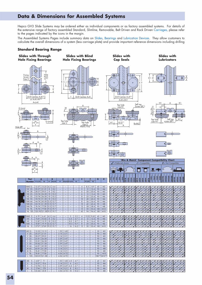
54
Data & Dimensions for Assembled Systems
PartNumber
A B C D E HGF
12...20...28...25...35...50...44...60...76...76...120...
12.3720.3728.3725.7435.7450.7444.7460.7476.7476.74
120.74
13.2521.0129.0126.5836.3851.3845.5861.3877.3877.58
121.38
6.288101010
12.512.512.519.519.5
6.48.28.210.210.210.212.712.712.719.719.7
–––––––––––
–––––––––––
–––––––––––
–––––––––––
4566810810121545
8.512201525402642585094
8.912.420.415.425.440.426.442.458.450.494.4
459090909090909090180180
M3M4M5M5M6M6M6M8M8M12M10
P1 & P2 P2 & P3 P2 & P3 P1 & P2 P1 & P2P3 P1 P1 P3 P3
E...E...E...E...E...
6.199.6912.8718.8727.37
6.4110.0213.1919.1927.69
6.2810
12.519.5
6.48.210.212.719.7
–––––
–––––
56.58.510.516
5.36.78.710.716.2
446812
9.2512162030
9.6512.416.420.430.4
45909090180
M3M4M5M6M10
12...20...28...25...35...50...44...60...76...76...120...
12.5520.3728.3725.8135.8150.8244.8160.8176.8176.81
120.81
13.1321.0129.0126.5836.5851.5845.5861.5877.3877.58
121.58
–––––––––––
–––––––––––
1.522.142.142.392.392.393.143.143.144.564.56
1.602.212.212.472.472.473.213.213.214.724.72
–––––––––––
–––––––––––
–––––––––––
–––––––––––
–––––––––––
30909090909090909090
180*3
M3M4M5M6M6M6M6M8M8M10
M10*3
E...E...E...E...E...
NMSNVNVNSNSNSNMNMNMNLNL
NMSNVNSNMNL
MSVVSSSMMMLL
MSV S M L
6.8710.3712.9617.4622.46
7.110.613.317.822.8
–––––
–––––
1.522.142.393.144.56
1.602.212.473.214.72
4.56
6.5810
4.76.26.78.210.2
–––––
–––––
–––––
4590909090
M3M4M5M6M8
FixingScrewSize H
HolePitchG*2
Drill Centres A+K*3
or A+K+W*3
A+J+K
Q (min)
BEF
Q (max)
Hole ØP
M
C
A
A
K
D
N
R S J K
T Drill Centres A+K
MA
Tap holesize U Tap hole
size VMetric Fine
X
Z
C
A D
BEF
D1 E1 F1
X Y
A+K+2A1
Tap holesize B1
Self tapScrew ØC1
Self tapscrew ØP1
H1 A K1G1J1
M
M1Tap holesize N1
B+M-ZA
A1 K/2*1
Drill Centres A+K*1
Hepco GV3 Slide Systems may be ordered either as individual components or as factory assembled systems. For details of the extensive range of factory assembled Standard, Slimline, Removable, Belt Driven and Rack Driven Carriages, please refer to the pages indicated by the icons in the margin.The Assembled Systems Pages include summary data on Slides, Bearings and Lubrication Devices. They allow customers to calculate the overall dimensions of a system (less carriage plate) and provide important reference dimensions including drilling
...J
13...
...J
18...
...J
25
...
...J
34...
...J
54...
CS18
CS25
CS34
CS5
4
LB12
LB20
LB25
LB4
4
LB76
...J
195
...
...J
265
...
...J
360...
...J
580...
CW
195
CW
265
CW
360
CW
580
LB19
5
LB265
LB360
LB5
80
‘Mix & Match’ Component Compatibility Chart= Preferred choice = Compatible = Not Compatible
Slides with ThroughHole Fixing Bearings
Slides with BlindHole Fixing Bearings
Slides withCap Seals
Slides withLubricators
Standard Bearing Range
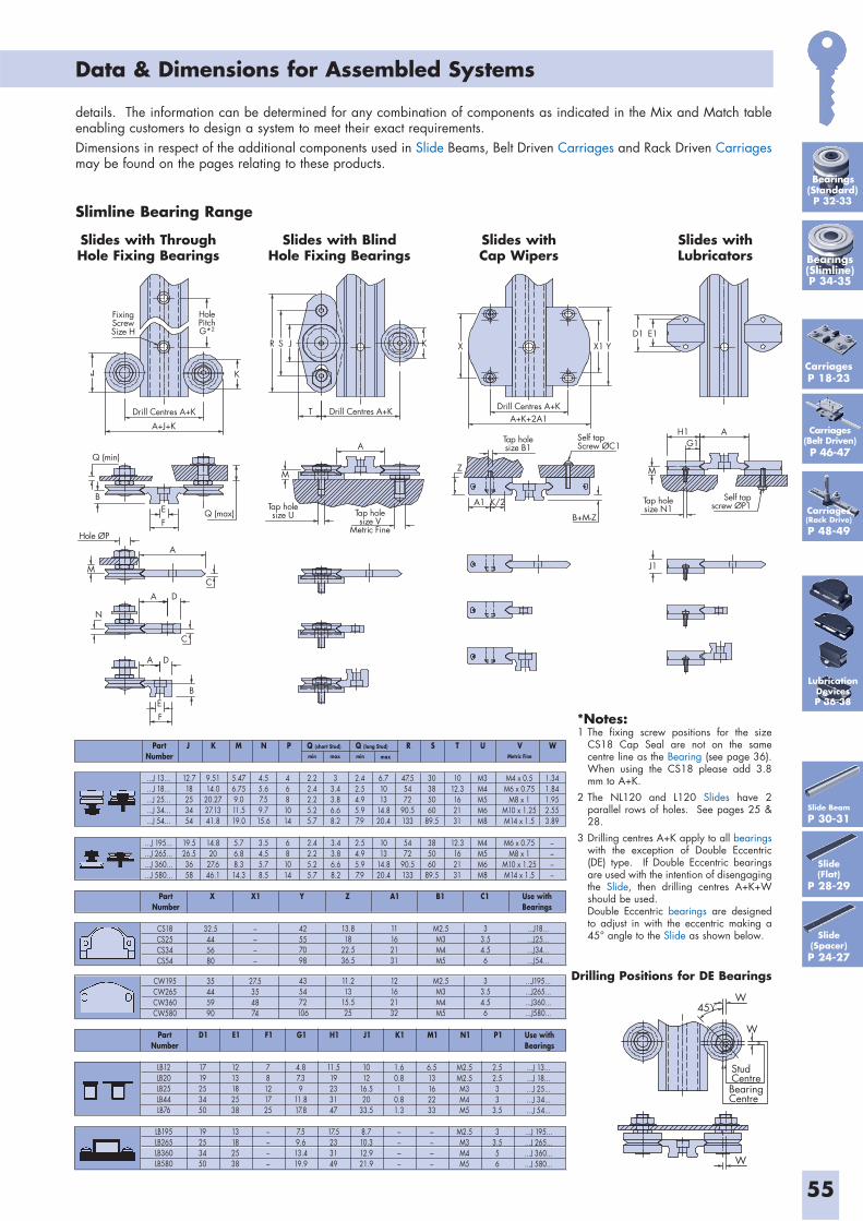
55
Data & Dimensions for Assembled Systems
HolePitchG*2
FixingScrewSize H
K
Drill Centres A+K
A+J+K
R S J K
T Drill Centres A+K
Q (min)
BEF
Q (max)
Hole ØP
M
Tap holesize U Tap hole
size VMetric Fine
A
A
A
A
D
D
C
C
B
M
N
EF
J1
D1 E1X1 YX
Drill Centres A+KA+K+2A1
Tap holesize B1
Tap holesize N1
Self tapScrew ØC1
Self tapscrew ØP1
H1 AG1
M
B+M-Z
Z
A1 K/2
Slide(Spacer)P 24-27
Slide Beam
P 30-31
Slide(Flat)
P 28-29
PartNumber
Q (short Stud) Q (long Stud) WJ K M N P R S T U V
...J 13...
...J 18...
...J 25...
...J 34...
...J 54...
12.718253454
9.5114.0
20.2727.1341.8
5.476.759.011.519.0
4.55.67.59.715.6
4681014
2.22.42.25.25.7
33.43.86.68.2
2.42.54.95.97.9
6.71013
14.820.4
47.55472
90.5133
30385060
89.5
1012.3162131
M3M4M5M6M8
1.341.841.952.553.89
M4 x 0.5M6 x 0.75
M8 x 1M10 x 1.25M14 x 1.5
...J 195...
...J 265...
...J 360...
...J 580...
19.526.53658
14.820
27.646.1
5.76.88.314.3
3.54.55.78.5
681014
2.42.25.25.7
3.43.86.68.2
2.54.95.97.9
1013
14.820.4
5472
90.5133
385060
89.5
12.3162131
M4M5M6M8
––––
M6 x 0.75M8 x 1
M10 x 1.25M14 x 1.5
min max min max Metric Fine
PartNumber
LB12LB20LB25LB44LB76
LB195LB265LB360LB580
D1
1719253450
19253450
E1
1213182538
13182538
F1
78121725
––––
G1
4.87.39
11.817.8
7.59.613.419.9
H1
11.519233147
17.5233149
J1
1012
16.520
33.5
8.710.312.921.9
K1
1.60.81
0.81.3
––––
M1
6.513162233
––––
N1
M2.5M2.5M3M4M5
M2.5M3M4M5
P1
2.52.533
3.5
33.556
Use withBearings
...J 13...
...J 18...
...J 25...
...J 34...
...J 54...
...J 195...
...J 265...
...J 360...
...J 580...
PartNumber
X X1 Y Z A1 B1 C1 Use withBearings
CS18CS25CS34CS54
CW195CW265CW360CW580
32.5445680
35445990
––––
27.5354874
42557098
435472106
13.818
22.536.5
11.213
15.525
11162131
12162132
M2.5M3M4M5
M2.5M3M4M5
33.54.56
33.54.56
...J18...
...J25...
...J34...
...J54...
...J195...
...J265...
...J360...
...J580...
*Notes:1 The fixing screw positions for the size
CS18 Cap Seal are not on the same centre line as the Bearing (see page 36). When using the CS18 please add 3.8 mm to A+K.
2 The NL120 and L120 Slides have 2 parallel rows of holes. See pages 25 & 28.
3 Drilling centres A+K apply to all bearings with the exception of Double Eccentric (DE) type. If Double Eccentric bearings are used with the intention of disengaging the Slide, then drilling centres A+K+W should be used.
Double Eccentric bearings are designed to adjust in with the eccentric making a 45° angle to the Slide as shown below.
details. The information can be determined for any combination of components as indicated in the Mix and Match table enabling customers to design a system to meet their exact requirements.Dimensions in respect of the additional components used in Slide Beams, Belt Driven Carriages and Rack Driven Carriages may be found on the pages relating to these products.
Slides with ThroughHole Fixing Bearings
Slides with BlindHole Fixing Bearings
Slides withCap Wipers
Slides withLubricators
Slimline Bearing Range
StudCentreBearingCentre
W
W
W
45
Drilling Positions for DE Bearings
CarriagesP 18-23
Carriages(Belt Driven)P 46-47
Carriages(Rack Drive)
P 48-49
Bearings(Standard)P 32-33
Bearings(Slimline)P 34-35
LubricationDevicesP 36-38
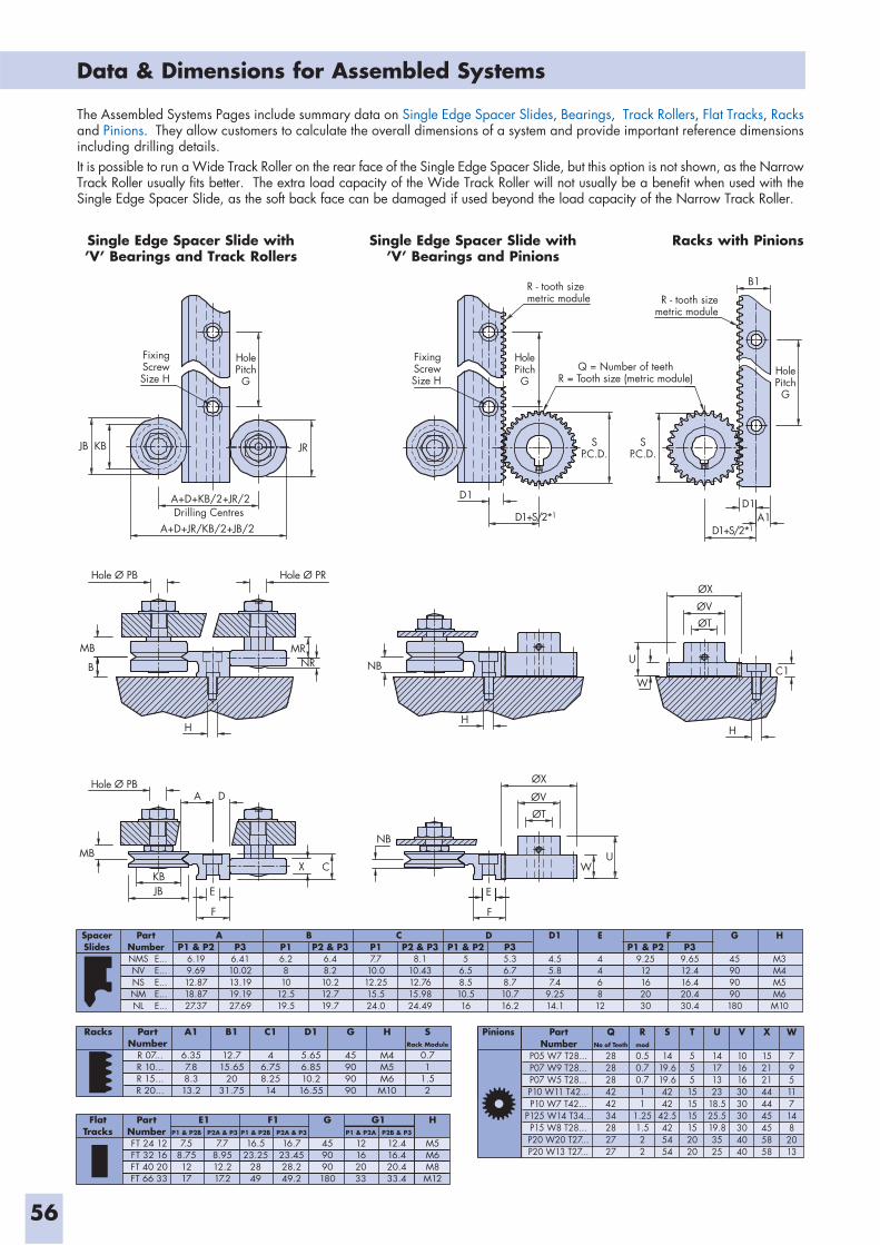
56
Data & Dimensions for Assembled Systems
FixingScrewSize H
JB KB JR
HolePitchG
FixingScrewSize H
D1
SP.C.D.
SP.C.D.
HolePitchG
R - tooth sizemetric module R - tooth size
metric module
B1
HolePitchG
A1D1
D1+S/2*1
Q = Number of teethR = Tooth size (metric module)
D1+S/2*1
A+D+KB/2+JR/2
A+D+JR/KB/2+JB/2
Hole Ø PB Hole Ø PR
MRNR NB
HH
AHole Ø PB
KBJB E
F
X C
NB
W
U
ØX
ØVØT
C1
H
E
F
UW
ØX
ØV
ØT
D
MB
MB
B
Drilling Centres
NMSNVNSNMNL
E...E...E...E...E...
SpacerSlides
PartNumber P1 & P2
6.199.6912.8718.8727.37
P2 & P36.48.210.212.719.7
P36.4110.0213.1919.1927.69
AP16.2810
12.519.5
BP2 & P3
8.110.4312.7615.9824.49
P17.7
10.012.2515.524.0
CP35.36.78.710.716.2
D1
4.55.87.4
9.2514.1
E
446812
G
45909090180
H
M3M4M5M6M10
P1 & P25
6.58.510.516
DP3
9.6512.416.420.430.4
P1 & P29.2512162030
F
R 07...R 10...R 15...R 20...
Racks PartNumber
A1
6.357.88.313.2
B1
12.715.65
2031.75
C1
46.758.2514
D1
5.656.8510.2
16.55
G
45909090
H
M4M5M6M10
SRack Module
0.71
1.52
FT 24 12FT 32 16FT 40 20FT 66 33
FlatTracks
PartNumber P1 & P2B
7.58.751217
P2A & P3
7.78.9512.217.2
E1P1 & P2B
16.523.25
2849
P2A & P3
16.723.4528.249.2
G
459090180
H
M5M6M8M12
F1P1 & P2A
12162033
P2B & P3
12.416.420.433.4
G1
P05 W7 T28...P07 W9 T28...P07 W5 T28...P10 W11 T42...P10 W7 T42...
P125 W14 T34...P15 W8 T28...P20 W20 T27...P20 W13 T27...
Pinions PartNumber
QNo of Teeth
282828424234282727
Rmod
0.50.70.711
1.251.522
S
1419.619.64242
42.5425454
T
555151515152020
U
14171323
18.525.519.83525
V
101616303030304040
X
152121444445455858
W
7951171482013
Single Edge Spacer Slide with’V’ Bearings and Track Rollers
Single Edge Spacer Slide with’V’ Bearings and Pinions
Racks with Pinions
The Assembled Systems Pages include summary data on Single Edge Spacer Slides, Bearings, Track Rollers, Flat Tracks, Racks and Pinions. They allow customers to calculate the overall dimensions of a system and provide important reference dimensions including drilling details. It is possible to run a Wide Track Roller on the rear face of the Single Edge Spacer Slide, but this option is not shown, as the Narrow Track Roller usually fits better. The extra load capacity of the Wide Track Roller will not usually be a benefit when used with the Single Edge Spacer Slide, as the soft back face can be damaged if used beyond the load capacity of the Narrow Track Roller.
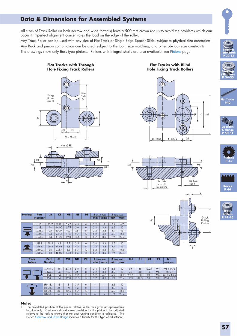
57
Data & Dimensions for Assembled Systems
FixingScrewSize H
JRJR M1
Q1F1+JR/2E1+JR/2
K1JR
E1
E1+ F1+JR
F1
MR
MR MR
Z
Z
G1+JRDrillingCentres
G1
Tap holesize P1
Tap holesize N1
metric fine
NR
H
NR
MR
Hole Ø PR
HolePitchG
Bearings PartNumber min max
JB KB MB NB PB Z (short stud)
min maxZ (long stud)
...J13...
...J18...
...J25...
...J34...
...J54...
12.718253454
9.5114.0020.2727.1341.76
5.476.759.011.519.0
4.55.67.59.715.6
4681014
2.22.42.25.25.7
33.43.86.68.2
2.42.54.95.97.9
6.71013
14.820.4
...J195...
...J265...
...J360...
...J580...
19.526.53658
14.819.9827.5746.08
5.76.88.314.3
3.54.55.78.5
681014
2.42.25.25.7
3.43.86.68.2
2.54.95.97.9
1013
14.820.4
TrackRollers
PartNumber min max
Z (short stud)JR MR NR PR K1 Q1 P1 N1Metric Fine
M1min maxZ (long stud)
...R18...
...R25...
...R34...
...R54...
18253454
6.759.011.519.0
5.67.59.715.6
681014
2.42.25.25.7
3.43.86.68.2
2.54.95.97.9
1013
14.820.4
5472
90.5133
385060
89.5
12.25162131
M4M5M6M8
M6 x 0.75M8 x 1
M10 x 1.25M14 x 1.5
LRN18...LRN25...LRN34...LRN54...
18253454
810
12.521
3.54.55.78.5
681014
––––
––––
2.54.95.97.9
1013
14.820.4
Flat Tracks with Through Hole Fixing Track Rollers
Flat Tracks with Blind Hole Fixing Track Rollers
Note:1 The calculated position of the pinion relative to the rack gives an approximate
location only. Customers should make provision for the pinion to be adjusted relative to the rack to ensure that the best running condition is achieved. The Hepco Gearbox and Drive Flange includes a facility for this type of adjustment.
Bearings(Standard)P 32-33
Bearings(Slimline)P 34-35
Flat TracksP40
Gearbox& FlangeP 50-51
RacksP 44
PinionsP 45
TrackRollersP 41-43
All sizes of Track Roller (in both narrow and wide formats) have a 500 mm crown radius to avoid the problems which can occur if imperfect alignment concentrates the load on the edge of the roller.Any Track Roller can be used with any size of Flat Track or Single Edge Spacer Slide, subject to physical size constraints. Any Rack and pinion combination can be used, subject to the tooth size matching, and other obvious size constraints.The drawings show only Boss type pinions. Pinions with integral shafts are also available, see Pinions page.
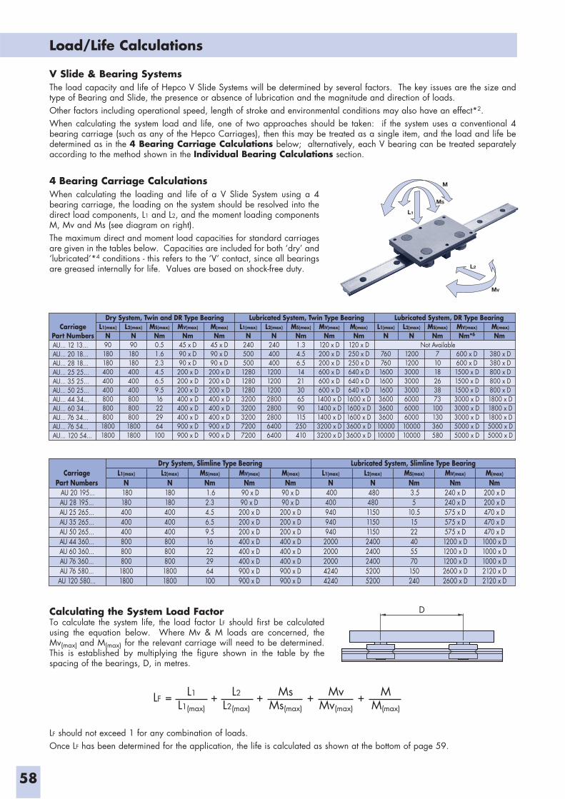
58
Load/Life Calculations
V Slide & Bearing SystemsThe load capacity and life of Hepco V Slide Systems will be determined by several factors. The key issues are the size and type of Bearing and Slide, the presence or absence of lubrication and the magnitude and direction of loads.Other factors including operational speed, length of stroke and environmental conditions may also have an effect*2.When calculating the system load and life, one of two approaches should be taken: if the system uses a conventional 4 bearing carriage (such as any of the Hepco Carriages), then this may be treated as a single item, and the load and life be determined as in the 4 Bearing Carriage Calculations below; alternatively, each V bearing can be treated separately according to the method shown in the Individual Bearing Calculations section.
4 Bearing Carriage CalculationsWhen calculating the loading and life of a V Slide System using a 4 bearing carriage, the loading on the system should be resolved into the direct load components, L1 and L2, and the moment loading components M, Mv and Ms (see diagram on right).The maximum direct and moment load capacities for standard carriages are given in the tables below. Capacities are included for both ‘dry’ and ‘lubricated’*4 conditions - this refers to the ‘V’ contact, since all bearings are greased internally for life. Values are based on shock-free duty.
CarriagePart Numbers
L1(max)
N9018018040040040080080080018001800
L2(max)
N9018018040040040080080080018001800
MS(max)
Nm0.51.62.34.56.59.516222964100
MV(max)
Nm45 x D90 x D90 x D
200 x D200 x D200 x D400 x D400 x D400 x D900 x D900 x D
M(max)
Nm45 x D90 x D90 x D
200 x D200 x D200 x D400 x D400 x D400 x D900 x D900 x D
L1(max)
N24050050012801280128032003200320072007200
L2(max)
N24040040012001200120028002800280064006400
MS(max)
Nm1.34.56.51421306590115250410
MV(max)
Nm120 x D200 x D200 x D600 x D600 x D600 x D1400 x D1400 x D1400 x D3200 x D3200 x D
M(max)
Nm120 x D250 x D250 x D640 x D640 x D640 x D1600 x D1600 x D1600 x D3600 x D3600 x D
L1(max)
N
760760
1600160016003600360036001000010000
L2(max)
N
120012003000300030006000600060001000010000
MS(max)
Nm 71018263873100130360580
MV(max)
Nm*6
600 x D600 x D1500 x D1500 x D1500 x D3000 x D3000 x D3000 x D5000 x D5000 x D
M(max)
Nm
380 x D380 x D800 x D800 x D800 x D1800 x D1800 x D1800 x D5000 x D5000 x D
Not Available
Dry System, Twin and DR Type Bearing Lubricated System, Twin Type Bearing Lubricated System, DR Type Bearing
AU... 12 13...AU... 20 18...AU... 28 18...AU... 25 25...AU... 35 25...AU... 50 25...AU... 44 34...AU... 60 34...AU... 76 34...AU... 76 54...AU... 120 54...
CarriagePart Numbers AU 20 195...AU 28 195...AU 25 265...AU 35 265...AU 50 265...AU 44 360...AU 60 360...AU 76 360...AU 76 580...
AU 120 580...
L1(max)
N 18018040040040080080080018001800
L2(max)
N18018040040040080080080018001800
MS(max)
Nm 1.62.34.56.59.516222964100
MV(max)
Nm 90 x D90 x D
200 x D200 x D200 x D400 x D400 x D400 x D900 x D900 x D
M(max)
Nm90 x D90 x D
200 x D200 x D200 x D400 x D400 x D400 x D900 x D900 x D
L1(max)
N 400400940940940
20002000200042404240
L2(max)
N 48048011501150115024002400240052005200
MS(max)
Nm 3.55
10.51522405570150240
MV(max)
Nm240 x D240 x D575 x D575 x D575 x D1200 x D1200 x D1200 x D2600 x D2600 x D
M(max)
Nm200 x D200 x D470 x D470 x D470 x D1000 x D1000 x D1000 x D2120 x D2120 x D
Dry System, Slimline Type Bearing Lubricated System, Slimline Type Bearing
Calculating the System Load FactorTo calculate the system life, the load factor LF should first be calculated using the equation below. Where Mv & M loads are concerned, the Mv(max) and M(max) for the relevant carriage will need to be determined. This is established by multiplying the figure shown in the table by the spacing of the bearings, D, in metres.
D
LF = + + + +L1
L1(max)
L2
L2(max)
MM(max)
MsMs(max)
MvMv(max)
LF should not exceed 1 for any combination of loads.Once LF has been determined for the application, the life is calculated as shown at the bottom of page 59.
M
L1
MS
L2
MV
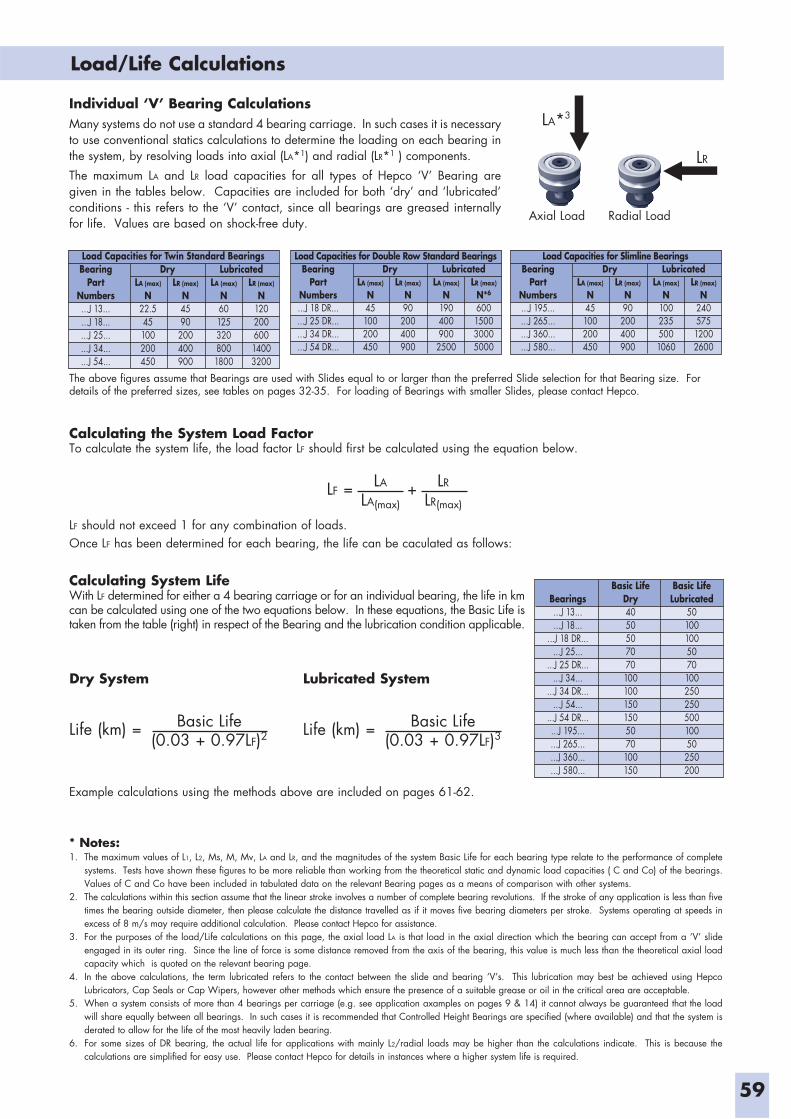
59
Load/Life Calculations
Individual ‘V’ Bearing CalculationsMany systems do not use a standard 4 bearing carriage. In such cases it is necessary to use conventional statics calculations to determine the loading on each bearing in the system, by resolving loads into axial (LA*1) and radial (LR*1 ) components.
The maximum LA and LR load capacities for all types of Hepco ‘V’ Bearing are given in the tables below. Capacities are included for both ‘dry’ and ‘lubricated’ conditions - this refers to the ‘V’ contact, since all bearings are greased internally for life. Values are based on shock-free duty.
LA*3
LR
Axial Load Radial Load
Load Capacities for Twin Standard BearingsBearing
PartNumbers...J 13......J 18......J 25......J 34......J 54...
LA (max)
N22.545100200450
LR (max)
N4590
200400900
LR (max)
N12020060014003200
LA (max)
N601253208001800
Dry LubricatedLoad Capacities for Double Row Standard Bearings
BearingPart
Numbers...J 18 DR......J 25 DR......J 34 DR......J 54 DR...
LA (max)
N45100200450
LR (max)
N90
200400900
LR (max)
N*6
600150030005000
LA (max)
N1904009002500
Dry LubricatedLoad Capacities for Slimline Bearings
BearingPart
Numbers...J 195......J 265......J 360......J 580...
LA (max)
N45100200450
LR (max)
N90
200400900
LR (max)
N24057512002600
LA (max)
N1002355001060
Dry Lubricated
Calculating the System Load FactorTo calculate the system life, the load factor LF should first be calculated using the equation below.
LF = +LA
LA(max)
LR
LR(max)
LF should not exceed 1 for any combination of loads.Once LF has been determined for each bearing, the life can be caculated as follows:
Calculating System LifeWith LF determined for either a 4 bearing carriage or for an individual bearing, the life in km can be calculated using one of the two equations below. In these equations, the Basic Life is taken from the table (right) in respect of the Bearing and the lubrication condition applicable.
Bearings...J 13......J 18...
...J 18 DR......J 25...
...J 25 DR......J 34...
...J 34 DR......J 54...
...J 54 DR......J 195......J 265......J 360......J 580...
Basic LifeDry40505070701001001501505070100150
Basic LifeLubricated
50100100507010025025050010050
250200
Dry System
Life (km) = Basic Life(0.03 + 0.97LF)2
Lubricated System
Life (km) = Basic Life(0.03 + 0.97LF)3
Example calculations using the methods above are included on pages 61-62.
* Notes:1. The maximum values of L1, L2, Ms, M, Mv, LA and LR, and the magnitudes of the system Basic Life for each bearing type relate to the performance of complete
systems. Tests have shown these figures to be more reliable than working from the theoretical static and dynamic load capacities ( C and Co) of the bearings. Values of C and Co have been included in tabulated data on the relevant Bearing pages as a means of comparison with other systems.
2. The calculations within this section assume that the linear stroke involves a number of complete bearing revolutions. If the stroke of any application is less than five times the bearing outside diameter, then please calculate the distance travelled as if it moves five bearing diameters per stroke. Systems operating at speeds in excess of 8 m/s may require additional calculation. Please contact Hepco for assistance.
3. For the purposes of the load/Life calculations on this page, the axial load LA is that load in the axial direction which the bearing can accept from a ‘V’ slide engaged in its outer ring. Since the line of force is some distance removed from the axis of the bearing, this value is much less than the theoretical axial load capacity which is quoted on the relevant bearing page.
4. In the above calculations, the term lubricated refers to the contact between the slide and bearing ‘V’s. This lubrication may best be achieved using Hepco Lubricators, Cap Seals or Cap Wipers, however other methods which ensure the presence of a suitable grease or oil in the critical area are acceptable.
5. When a system consists of more than 4 bearings per carriage (e.g. see application axamples on pages 9 & 14) it cannot always be guaranteed that the load will share equally between all bearings. In such cases it is recommended that Controlled Height Bearings are specified (where available) and that the system is derated to allow for the life of the most heavily laden bearing.
6. For some sizes of DR bearing, the actual life for applications with mainly L2/radial loads may be higher than the calculations indicate. This is because the calculations are simplified for easy use. Please contact Hepco for details in instances where a higher system life is required.
The above figures assume that Bearings are used with Slides equal to or larger than the preferred Slide selection for that Bearing size. For details of the preferred sizes, see tables on pages 32-35. For loading of Bearings with smaller Slides, please contact Hepco.
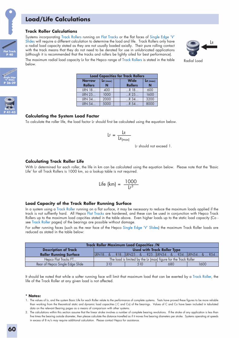
60
Load/Life Calculations
Track Roller CalculationsSystems incorporating Track Rollers running on Flat Tracks or the flat faces of Single Edge ‘V’ Slides will require a different calculation to determine the load and life. Track Rollers only have a radial load capacity stated as they are not usually loaded axially. Their pure rolling contact with the track means that they do not need to be derated for use in unlubricated applications (although it is recommended that the tracks and rollers be lightly oiled for best performance).The maximum radial load capacity LR for the Hepco range of Track Rollers is stated in the table below.
LR
Radial Load
Calculating the System Load FactorTo calculate the roller life, the load factor LF should first be calculated using the equation below.
LF = LR
LR(max)
LF should not exceed 1.
NarrowRollers
LRN 18...LRN 25...LRN 34...LRN 54...
LR (max)
N400100020005000
WideRollers...R 18......R 25......R 34......R 54...
LR (max)
N600160032008000
Load Capacities for Track Rollers
Calculating Track Roller LifeWith LF determined for each roller, the life in km can be calculated using the equation below. Please note that the ‘Basic Life’ for all Track Rollers is 1000 km, so a lookup table is not required.
Life (km) = 1000LF3
Load Capacity of the Track Roller Running SurfaceIn a system using a Track Roller running on a flat surface, it may be necessary to reduce the maximum loads applied if the track is not suffiently hard. All Hepco Flat Tracks are hardened, and these can be used in conjunction with Hepco Track Rollers up to the maximum load capcities stated in the table above. Even higher loads up to the static load capacity (Co - see Track Roller pages) of the bearings are possible without damage.For softer running faces (such as the rear face of the Hepco Single Edge ‘V’ Slides) the maximum Track Roller loads are reduced as stated in the table below:
Description of TrackRoller Running Surface
Hepco Flat Tracks FT...Rear of Hepco Single Edge Slide
LRN18... & ... R18...
310
LRN25... & ... R25...
510
LRN34... & ... R34...
680
LRN54... & ... R54...
1600
The load is limited by the LR (max) figure for the Track Roller
Used with Track Roller TypeTrack Roller Maximum Load Capacities /N
It should be noted that while a softer running face will limit that maximum load that can be exerted by a Track Roller, the life of the Track Roller at any given load is not affected.
Track RollersP 41-43
Single Edge‘V’ Slides
P 26-29
Flat TrackP 40
* Notes:1. The values of LR, and the system Basic Life for each Roller relate to the performance of complete systems. Tests have proved these figures to be more reliable
than working from the theoretical static and dynamic load capacities ( C and Co) of the bearings. Values of C and Co have been included in tabulated data on the relevant Bearing pages as a means of comparison with other systems.
2. The calculations within this section assume that the linear stroke involves a number of complete bearing revolutions. If the stroke of any application is less than five times the bearing outside diameter, then please calculate the distance travelled as if it moves five bearing diameters per stroke. Systems operating at speeds in excess of 8 m/s may require additional calculation. Please contact Hepco for assistance.
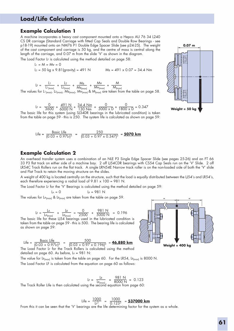
61
Load/Life Calculations
Example Calculation 1A machine incorporates a heavy cast component mounted onto a Hepco AU 76 34 L240 CS DR carriage (Standard Carriage with fitted Cap Seals and Double Row Bearings - see p18-19) mounted onto an NM76 P1 Double Edge Spacer Slide (see p24-25). The weight of the cast component and carriage is 50 kg, and the centre of mass is central along the length of the carriage, and 0.07 m from the slide ‘V’ as shown in the diagram.The Load Factor LF is calculated using the method detailed on page 58: L1 = M = Mv = 0 L2 = 50 kg x 9.81(gravity) = 491 N Ms = 491 x 0.07 = 34.4 Nm
The values for L1(max), L2(max), Ms(max), Mv(max) & M(max) are taken from the table on page 58.
The basic life for this system (using SJ34DR bearings in the lubricated condition) is taken from the table on page 59 - this is 250. The system life is calculated as shown on page 59:
0.07 m
Weight = 50 kg
LF = + + + +L1
L1(max)
L2
L2(max)
MM(max)
MsMs(max)
MvMv(max)
LF = + + + + = 0.34703600
491 N6000 N
01800 x D
34.4 Nm130 Nm
03000 x D
Life = = = 5070 kmBasic Life(0.03 + 0.97LF)3
250(0.03 + 0.97 x 0.347)3
Example Calculation 2An overhead transfer system uses a combination of an NLE P3 Single Edge Spacer Slide (see pages 25-26) and an FT 66 33 P3 flat track on either side of a machine bay. 2 off LJ54CDR bearings with CS54 Cap Seals run on the ‘V’ Slide. 2 off LR54C Track Rollers run on the flat track. A single LRN54E Narrow track roller is on the non-loaded side of both the ‘V’ slide and Flat Track to retain the moving structure on the slides.A weight of 400 kg is located centrally on the structure, such that the load is equally distributed between the LJ54’s and LR54’s, each therefore experiencing a radial load of 9.81 x 100 = 981 N.The Load Factor LF for the ‘V’ Bearings is calculated using the method detailed on page 59: LA = 0 LR = 981 N
The values for LA(max) & LR(max) are taken from the table on page 59.
The basic life for these LJ54 bearings used in the lubricated condition is taken from the table on page 59 - this is 500. The bearing life is calculated as shown on page 59:
The Load Factor LF for the Track Rollers is calculated using the method detailed on page 60. As before, LR = 981 N: The value for LR(max) is taken from the table on page 60. For the LR54, LR(max) is 8000 N.The Load Factor LF is calculated from the equation on page 60 as follows:
The Track Roller Life is then calculated using the second equation from page 60:
From this it can be seen that the ‘V’ bearings are the life determining factor for the system as a whole.
LF = + = + = 0.196LR
LR(max)
LA
LA(max)
981 N5000 N
02500
Life = = = 46,880 kmBasic Life(0.03 + 0.97LF)3
500(0.03 + 0.97 x 0.196)3 Weight = 400 kg
= =
LF = = = 0.123LR
LR(max)
981 N8000 N
Life = = = 537000 km1000LF3
10000.1233
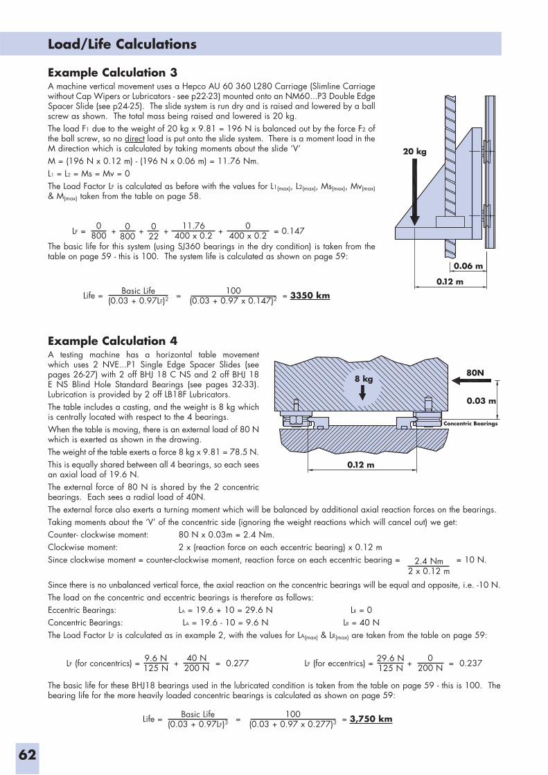
62
Load/Life Calculations
Example Calculation 3A machine vertical movement uses a Hepco AU 60 360 L280 Carriage (Slimline Carriage without Cap Wipers or Lubricators - see p22-23) mounted onto an NM60...P3 Double Edge Spacer Slide (see p24-25). The slide system is run dry and is raised and lowered by a ball screw as shown. The total mass being raised and lowered is 20 kg.The load F1 due to the weight of 20 kg x 9.81 = 196 N is balanced out by the force F2 of the ball screw, so no direct load is put onto the slide system. There is a moment load in the M direction which is calculated by taking moments about the slide ‘V’ M = (196 N x 0.12 m) - (196 N x 0.06 m) = 11.76 Nm.L1 = L2 = Ms = Mv = 0 The Load Factor LF is calculated as before with the values for L1(max), L2(max), Ms(max), Mv(max) & M(max) taken from the table on page 58.
The basic life for this system (using SJ360 bearings in the dry condition) is taken from the table on page 59 - this is 100. The system life is calculated as shown on page 59:
20 kg
0.12 m
0.06 m
LF = + + + + = 0.1470800
0800
0400 x 0.2
022
11.76400 x 0.2
Life = = = 3350 kmBasic Life(0.03 + 0.97LF)2
100(0.03 + 0.97 x 0.147)2
Example Calculation 4A testing machine has a horizontal table movement which uses 2 NVE...P1 Single Edge Spacer Slides (see pages 26-27) with 2 off BHJ 18 C NS and 2 off BHJ 18 E NS Blind Hole Standard Bearings (see pages 32-33). Lubrication is provided by 2 off LB18F Lubricators.The table includes a casting, and the weight is 8 kg which is centrally located with respect to the 4 bearings.When the table is moving, there is an external load of 80 N which is exerted as shown in the drawing.The weight of the table exerts a force 8 kg x 9.81 = 78.5 N. This is equally shared between all 4 bearings, so each sees an axial load of 19.6 N.The external force of 80 N is shared by the 2 concentric bearings. Each sees a radial load of 40N.The external force also exerts a turning moment which will be balanced by additional axial reaction forces on the bearings. Taking moments about the ‘V’ of the concentric side (ignoring the weight reactions which will cancel out) we get:Counter- clockwise moment: 80 N x 0.03m = 2.4 Nm.Clockwise moment: 2 x (reaction force on each eccentric bearing) x 0.12 mSince clockwise moment = counter-clockwise moment, reaction force on each eccentric bearing = = 10 N.
Since there is no unbalanced vertical force, the axial reaction on the concentric bearings will be equal and opposite, i.e. -10 N.The load on the concentric and eccentric bearings is therefore as follows:Eccentric Bearings: LA = 19.6 + 10 = 29.6 N LR = 0Concentric Bearings: LA = 19.6 - 10 = 9.6 N LR = 40 NThe Load Factor LF is calculated as in example 2, with the values for LA(max) & LR(max) are taken from the table on page 59:
The basic life for these BHJ18 bearings used in the lubricated condition is taken from the table on page 59 - this is 100. The bearing life for the more heavily loaded concentric bearings is calculated as shown on page 59:
80N
0.03 m
0.12 m
8 kg
Concentric Bearings
2.4 Nm2 x 0.12 m
LF (for concentrics) = + = 0.27740 N200 N
9.6 N125 N LF (for eccentrics) = + = 0.2370
200 N29.6 N125 N
Life = = = 3,750 kmBasic Life(0.03 + 0.97LF)3
100(0.03 + 0.97 x 0.277)3
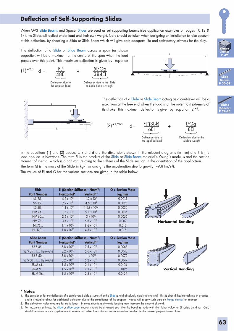
63
Deflection of Self-Supporting Slides
When GV3 Slide Beams and Spacer Slides are used as self-supporting beams (see application examples on pages 10,12 & 14), the Slides will deflect under load and their own weight. Care should be taken when designing an installation to take account of this deflection, by choosing a Slide or Slide Beam which will give both adequate life and satisfactory stiffness for the duty.
* Notes:1. The calculation for the deflection of a cantilevered slide assumes that the Slide is held absolutely rigidly at one end. This is often difficult to achieve in practice,
and it is usual to allow for additional deflection due to the compliance of the support. Hepco will supply such data on flange clamps on request.2. The deflections calculated are for static loads. In some situations dynamic loading may increase the amount of bend.3. For maximum stiffness, the slide or slide beam section should be arranged such that the bending mode with the higher value for EI resists bending. Care
should be taken in such applications to ensure that offset loads do not cause excessive bending in the weaker perpendicular plane.
The deflection of a Slide or Slide Beam across a span (as shown opposite), will be a maximum at the centre of the span when the load passes over this point. This maximum deflection is given by equation
FL3
48EId =
L
F
d
k
F
L
d
(1)*2,3 5L4Qg384EI
+
Deflection due tothe applied load
Deflection due to the Slide or Slide Beam’s weight
The deflection of a Slide or Slide Beam acting as a cantilever will be a maximum at the free end when the load is at the outermost extremity of its stroke. This maximum deflection is given by equation (2)*1:
FL2(3L-k)6EI
d =(2)*1,2&3 L4Qg8EI
+
Deflection due tothe applied load
Deflection due to the Slide’s weight
In the equations (1) and (2) above, L, k and d are the dimensions shown in the relevant diagrams (in mm) and F is the load applied in Newtons. The term EI is the product of the Slide or Slide Beam material’s Young’s modulus and the section moment of inertia, which is a constant relating to the stiffness of the Slide section in the orientation of the application. The term Q is the mass of the Slide in kg/mm and g is the acceleration due to gravity (=9.81m/s2).The values of EI and Q for the various sections are given in the table below:
Slide BeamPart Number
SB S 35...SB S 35 ...L... (lightweight)
SB S 50...SB S 50 ...L... (lightweight)
SB M 44...SB M 60...SB M 76...
Q = Section Masskg/mm0.00680.00430.00720.00470.01040.01120.0129
Horizontal*3
5.8 x 10¹⁰
3.2 x 10¹⁰
5.8 x 10¹⁰
3.2 x 10¹⁰
1.5 x 10¹¹
1.5 x 10¹¹
1.5 x 10¹¹
Vertical*3
9.5 x 10¹⁰
5.6 x 10¹⁰
1 x 10¹¹
6.2 x 10¹⁰
2.1 x 10¹¹
2.3 x 10¹¹
2.5 x 10¹¹
El (Section Stiffness – Nmm2)
SlidePart Number
NS 25...NS 35...NS 50...NM 44...NM 60...NM 76...NL 76...
NL 120...
Q = Section Masskg/mm0.00150.00230.00320.00350.00550.0070.0100.015
Horizontal*3
4.2 x 10⁸
7.5 x 10⁸
1.1 x 10⁹
1.7 x 10⁹
2.6 x 10⁹
3.4 x 10⁹
1.1 x 10¹⁰
1.8 x 10¹⁰
Vertical*3
1.2 x 10⁹
4.6 x 10⁹
1.55 x 10¹⁰
9.8 x 10⁹
3 x 10¹⁰
6.8 x 10¹⁰
8.6 x 10¹⁰
4.3 x 10¹¹
El (Section Stiffness – Nmm2)
Horizontal Bending
Vertical Bending
Slides(Spacer)P 24-25
SlideBeams
P 30-31
FlangeClampsP 39
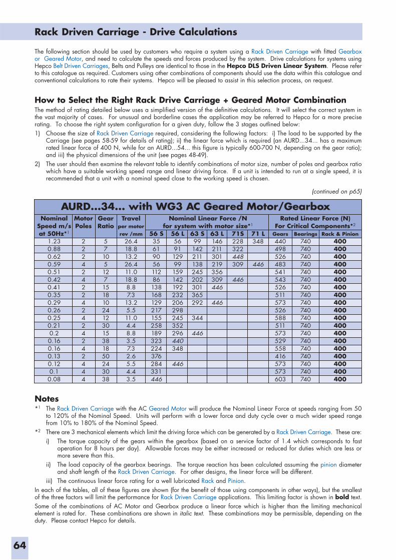
64
Notes*1 The Rack Driven Carriage with the AC Geared Motor will produce the Nominal Linear Force at speeds ranging from 50
to 120% of the Nominal Speed. Units will perform with a lower force and duty cycle over a much wider speed range from 10% to 180% of the Nominal Speed.
*2 There are 3 mechanical elements which limit the driving force which can be generated by a Rack Driven Carriage. These are:i) The torque capacity of the gears within the gearbox (based on a service factor of 1.4 which corresponds to fast
operation for 8 hours per day). Allowable forces may be either increased or reduced for duties which are less or more severe than this.
ii) The load capacity of the gearbox bearings. The torque reaction has been calculated assuming the pinion diameter and shaft length of the Rack Driven Carriage. For other designs, the linear force will be different.
iii) The continuous linear force rating for a well lubricated Rack and Pinion.In each of the tables, all of these figures are shown (for the benefit of those using components in other ways), but the smallest of the three factors will limit the performance for Rack Driven Carriage applications. This limiting factor is shown in bold text.Some of the combinations of AC Motor and Gearbox produce a linear force which is higher than the limiting mechanical element is rated for. These combinations are shown in italic text. These combinations may be permissible, depending on the duty. Please contact Hepco for details.
Rack Driven Carriage - Drive Calculations
The following section should be used by customers who require a system using a Rack Driven Carriage with fitted Gearbox or Geared Motor, and need to calculate the speeds and forces produced by the system. Drive calculations for systems using Hepco Belt Driven Carriages, Belts and Pulleys are identical to those in the Hepco DLS Driven Linear System. Please refer to this catalogue as required. Customers using other combinations of components should use the data within this catalogue and conventional calculations to rate their systems. Hepco will be pleased to assist in this selection process, on request.
How to Select the Right Rack Drive Carriage + Geared Motor CombinationThe method of rating detailed below uses a simplified version of the definitive calculations. It will select the correct system in the vast majority of cases. For unusual and borderline cases the application may be referred to Hepco for a more precise rating. To choose the right system configuration for a given duty, follow the 3 stages outlined below:1) Choose the size of Rack Driven Carriage required, considering the following factors: i) The load to be supported by the
Carriage (see pages 58-59 for details of rating); ii) the linear force which is required (an AURD...34... has a maximum rated linear force of 400 N, while for an AURD...54... this figure is typically 600-700 N, depending on the gear ratio); and iii) the physical dimensions of the unit (see pages 48-49).
2) The user should then examine the relevant table to identify combinations of motor size, number of poles and gearbox ratio which have a suitable working speed range and linear driving force. If a unit is intended to run at a single speed, it is recommended that a unit with a nominal speed close to the working speed is chosen.
NominalSpeed m/sat 50Hz*1
1.230.880.620.590.510.420.410.350.290.260.250.210.20.160.160.130.120.10.08
MotorPoles
2224242242424242444
GearRatio
5710512715181024123015381850243038
Travelper motorrev /mm
26.418.813.226.411.018.88.87.3
13.25.511.04.48.83.57.32.65.54.43.5
Rack & Pinion400400400400400400400400400400400400400400400400400400400
Bearings740740740740740740740740740740740740740740740740740740740
Gears440498526483541543526511573526588511573529558416573573603
Nominal Linear Force /Nfor system with motor size*1
Rated Linear Force (N)For Critical Components*2
56 S3561905611286138168129217155258189323224376284331446
56 L569112999159142192232206298245352296440348
446
63 S99142211138245202301365292
344
446
63 L146211301219356309446
446
71S228322448309
446
71 L348
446
AURD...34... with WG3 AC Geared Motor/Gearbox
(continued on p65)
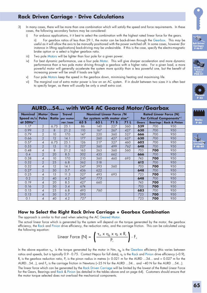
65
Rack Driven Carriage - Drive Calculations
NominalSpeed m/sat 50Hz*1
1.170.990.790.660.570.530.480.4
0.380.320.320.270.250.20.190.160.150.130.1
MotorPoles
2222424242424242444
GearRatio
6.7581012
6.75158201025123015402050253040
Travelper motorrev /mm
25.121.217.014.125.111.321.28.517.06.814.15.711.34.28.53.46.85.74.2
Rack & Pinion950950950950950950950950950950950950950950950950950950950
Bearings700700700700700700700700700700700700700700700700700700700
Gears539630666630602648703666743612703648723648743703683723723
Nominal Linear Force /Nfor system with motor size*1
Rated Linear Force (N)For Critical Components*2
63 S86110147177126227163302210362247436327547427674493593727
63 L140167220260217360263435360518393622493775660
760
71 S227267360427327499360662460
560
693
71 L360427527627460762560
693
AURD...54... with WG4 AC Geared Motor/Gearbox
3) In many cases, there will be more than one combination which will satisfy the speed and force requirements. In these cases, the following secondary factors may be considered:
i) For arduous applications, it it best to select the combination with the highest rated linear force for the gears. ii) For gearbox ratios of less than 29:1, the motor can be back-driven through the Gearbox. This may be
useful as it will allow the axis to be manually positioned with the power switched off. In some cases, however (for instance in lifting applications) back-driving may be undesirable. If this is the case, specify the electro-magnetic brake option or a select a higher gearbox ratio.
iii) Two pole Motors will be lighter than four pole for a given power.iv) For best dynamic performance, use a four pole Motor. This will give sharper acceleration and more dynamic
performance than a two pole motor driving through a gearbox with a higher ratio. For a given load, a more powerful motor will generally accelerate the system more quickly than a less powerful one, but the benefit of increasing power will be small if loads are light.
v) Four pole Motors keep the speed in the gearbox down, minimising heating and maximising life.vi) The marginal cost of extra motor power is low on an AC system. If in doubt between two sizes it is often best
to specify larger, as there will usually be only a small extra cost.
How to Select the Right Rack Drive Carriage + Gearbox CombinationThe approach is similar to that used when selecting the AC Geared Motor. The actual linear force which is generated by the system will depend on the torque generated by the motor, the gearbox efficiency, the Rack and Pinion drive efficiency, the reduction ratio, and the carriage friction. This can be calculated using the following equation:
In the above equation m is the torque generated by the motor in Nm, g is the Gearbox efficiency (this varies between ratios and speeds, but is typically 0.9 - 0.75. Contact Hepco for full data), r is the Rack and Pinion drive efficiency (~0.9), Rr is the gearbox reduction ratio, Pr is the pinon radius in metres (= 0.021 m for the AURD ...34... and = 0.027 m for the AURD...54...), and Fc is the carriage friction in Newtons (~25 N for the AURD ...34... and ~40 N for the AURD ...54...).The linear force which can be generated by the Rack Driven Carriage will be limited by the lowest of the Rated Linear Force for the Gears, Bearings and Rack & Pinion (as detailed in the tables above and on page 64). Customers should ensure that the motor torque selected does not overload the mechanical components.
Linear Force (N) = ( )m x g x r x Rr
Pr- Fc
Gearboxes& Geared
MotorsP50-51
Rack DrivenCarriagesP 48-49
Belt DrivenCarriagesP 46-47
PinionsP 45
RacksP 44
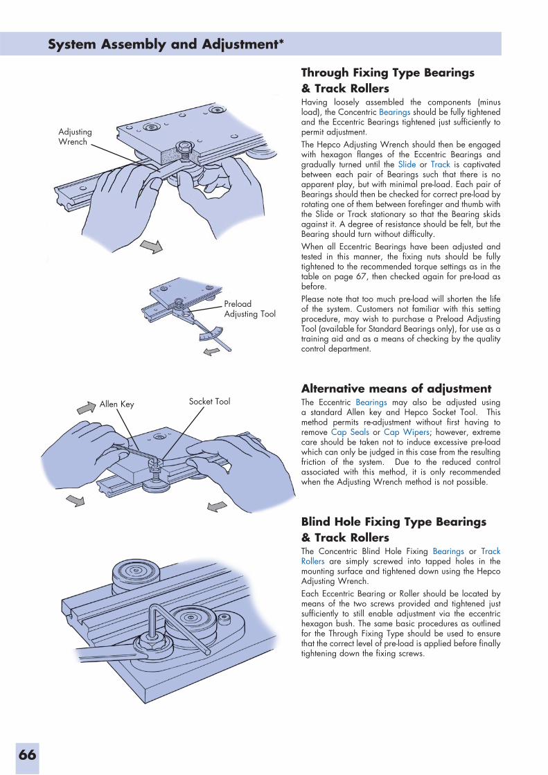
System Assembly and Adjustment*
66
Through Fixing Type Bearings & Track RollersHaving loosely assembled the components (minus load), the Concentric Bearings should be fully tightened and the Eccentric Bearings tightened just sufficiently to permit adjustment.The Hepco Adjusting Wrench should then be engaged with hexagon flanges of the Eccentric Bearings and gradually turned until the Slide or Track is captivated between each pair of Bearings such that there is no apparent play, but with minimal pre-load. Each pair of Bearings should then be checked for correct pre-load by rotating one of them between forefinger and thumb with the Slide or Track stationary so that the Bearing skids against it. A degree of resistance should be felt, but the Bearing should turn without difficulty.When all Eccentric Bearings have been adjusted and tested in this manner, the fixing nuts should be fully tightened to the recommended torque settings as in the table on page 67, then checked again for pre-load as before.Please note that too much pre-load will shorten the life of the system. Customers not familiar with this setting procedure, may wish to purchase a Preload Adjusting Tool (available for Standard Bearings only), for use as a training aid and as a means of checking by the quality control department.
Alternative means of adjustmentThe Eccentric Bearings may also be adjusted using a standard Allen key and Hepco Socket Tool. This method permits re-adjustment without first having to remove Cap Seals or Cap Wipers; however, extreme care should be taken not to induce excessive pre-load which can only be judged in this case from the resulting friction of the system. Due to the reduced control associated with this method, it is only recommended when the Adjusting Wrench method is not possible.
Blind Hole Fixing Type Bearings & Track RollersThe Concentric Blind Hole Fixing Bearings or Track Rollers are simply screwed into tapped holes in the mounting surface and tightened down using the Hepco Adjusting Wrench.Each Eccentric Bearing or Roller should be located by means of the two screws provided and tightened just sufficiently to still enable adjustment via the eccentric hexagon bush. The same basic procedures as outlined for the Through Fixing Type should be used to ensure that the correct level of pre-load is applied before finally tightening down the fixing screws.
Socket Tool
Adjusting Wrench
Allen Key
Preload Adjusting Tool
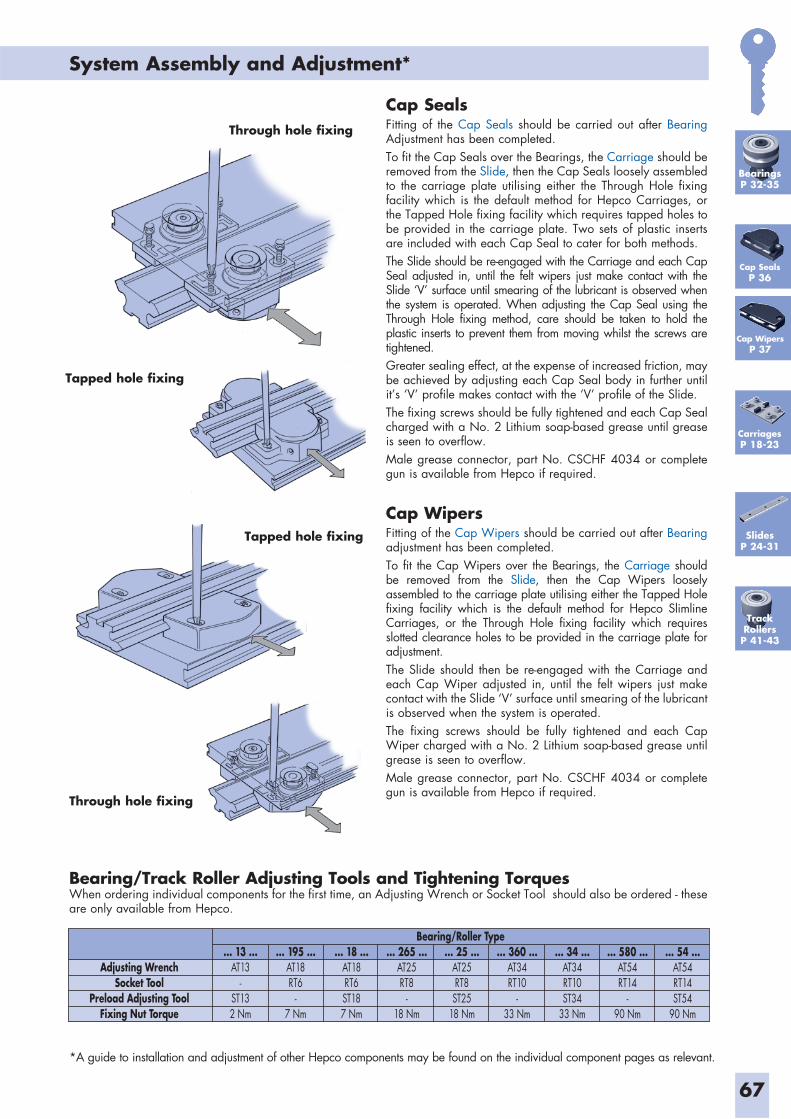
System Assembly and Adjustment*
67
Cap Seals Fitting of the Cap Seals should be carried out after Bearing Adjustment has been completed. To fit the Cap Seals over the Bearings, the Carriage should be removed from the Slide, then the Cap Seals loosely assembled to the carriage plate utilising either the Through Hole fixing facility which is the default method for Hepco Carriages, or the Tapped Hole fixing facility which requires tapped holes to be provided in the carriage plate. Two sets of plastic inserts are included with each Cap Seal to cater for both methods. The Slide should be re-engaged with the Carriage and each Cap Seal adjusted in, until the felt wipers just make contact with the Slide ‘V’ surface until smearing of the lubricant is observed when the system is operated. When adjusting the Cap Seal using the Through Hole fixing method, care should be taken to hold the plastic inserts to prevent them from moving whilst the screws are tightened. Greater sealing effect, at the expense of increased friction, may be achieved by adjusting each Cap Seal body in further until it’s ‘V’ profile makes contact with the ‘V’ profile of the Slide.The fixing screws should be fully tightened and each Cap Seal charged with a No. 2 Lithium soap-based grease until grease is seen to overflow.Male grease connector, part No. CSCHF 4034 or complete gun is available from Hepco if required.
Cap WipersFitting of the Cap Wipers should be carried out after Bearing adjustment has been completed. To fit the Cap Wipers over the Bearings, the Carriage should be removed from the Slide, then the Cap Wipers loosely assembled to the carriage plate utilising either the Tapped Hole fixing facility which is the default method for Hepco Slimline Carriages, or the Through Hole fixing facility which requires slotted clearance holes to be provided in the carriage plate for adjustment.The Slide should then be re-engaged with the Carriage and each Cap Wiper adjusted in, until the felt wipers just make contact with the Slide ‘V’ surface until smearing of the lubricant is observed when the system is operated. The fixing screws should be fully tightened and each Cap Wiper charged with a No. 2 Lithium soap-based grease until grease is seen to overflow.Male grease connector, part No. CSCHF 4034 or complete gun is available from Hepco if required.
Bearing/Track Roller Adjusting Tools and Tightening TorquesWhen ordering individual components for the first time, an Adjusting Wrench or Socket Tool should also be ordered - these are only available from Hepco.
... 13 ...AT13
-ST132 Nm
Adjusting WrenchSocket Tool
Preload Adjusting ToolFixing Nut Torque
... 195 ...AT18RT6
-7 Nm
... 18 ...AT18RT6ST187 Nm
... 265 ...AT25RT8
-18 Nm
... 25 ...AT25RT8ST25
18 Nm
... 360 ...AT34RT10
-33 Nm
... 34 ...AT34RT10ST34
33 Nm
... 580 ...AT54RT14
-90 Nm
... 54 ...AT54RT14ST54
90 Nm
Bearing/Roller Type
Cap SealsP 36
Cap WipersP 37
SlidesP 24-31
*A guide to installation and adjustment of other Hepco components may be found on the individual component pages as relevant.
BearingsP 32-35
Through hole fixing
Tapped hole fixing
Tapped hole fixing
Through hole fixing
TrackRollersP 41-43
CarriagesP 18-23
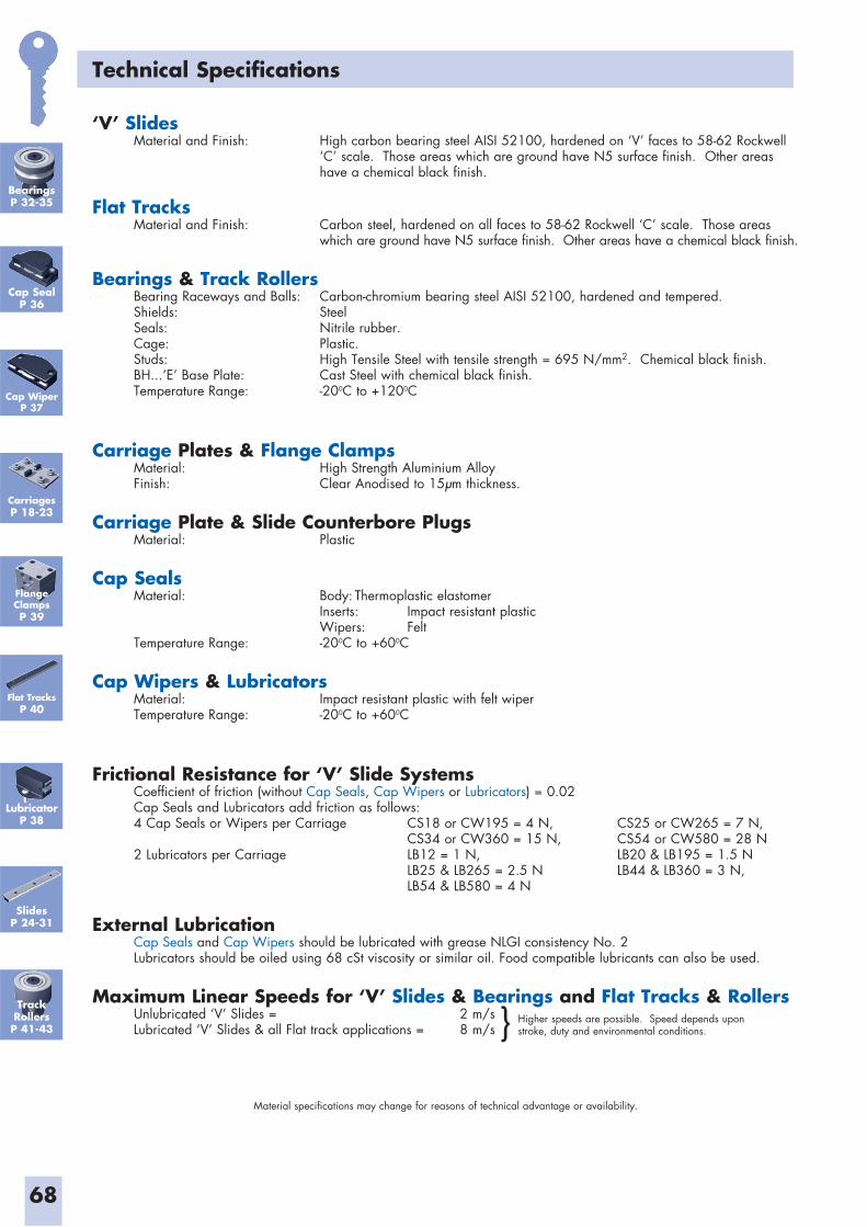
68
Technical Specifications
‘V’ Slides Material and Finish: High carbon bearing steel AISI 52100, hardened on ‘V’ faces to 58-62 Rockwell ‘C’ scale. Those areas which are ground have N5 surface finish. Other areas have a chemical black finish.
Flat Tracks Material and Finish: Carbon steel, hardened on all faces to 58-62 Rockwell ‘C’ scale. Those areas which are ground have N5 surface finish. Other areas have a chemical black finish.
Bearings & Track Rollers Bearing Raceways and Balls: Carbon-chromium bearing steel AISI 52100, hardened and tempered. Shields: Steel Seals: Nitrile rubber. Cage: Plastic. Studs: High Tensile Steel with tensile strength = 695 N/mm2. Chemical black finish. BH...‘E’ Base Plate: Cast Steel with chemical black finish. Temperature Range: -200C to +1200C
Carriage Plates & Flange Clamps Material: High Strength Aluminium Alloy Finish: Clear Anodised to 15μm thickness.
Carriage Plate & Slide Counterbore Plugs Material: Plastic
Cap Seals Material: Body: Thermoplastic elastomer Inserts: Impact resistant plastic Wipers: Felt Temperature Range: -200C to +600C
Cap Wipers & Lubricators Material: Impact resistant plastic with felt wiper Temperature Range: -200C to +600C
Frictional Resistance for ‘V’ Slide Systems Coefficient of friction (without Cap Seals, Cap Wipers or Lubricators) = 0.02 Cap Seals and Lubricators add friction as follows: 4 Cap Seals or Wipers per Carriage CS18 or CW195 = 4 N, CS25 or CW265 = 7 N, CS34 or CW360 = 15 N, CS54 or CW580 = 28 N 2 Lubricators per Carriage LB12 = 1 N, LB20 & LB195 = 1.5 N LB25 & LB265 = 2.5 N LB44 & LB360 = 3 N, LB54 & LB580 = 4 N
External Lubrication Cap Seals and Cap Wipers should be lubricated with grease NLGI consistency No. 2 Lubricators should be oiled using 68 cSt viscosity or similar oil. Food compatible lubricants can also be used.
Maximum Linear Speeds for ‘V’ Slides & Bearings and Flat Tracks & Rollers Unlubricated ‘V’ Slides = 2 m/s Lubricated ‘V’ Slides & all Flat track applications = 8 m/s
Material specifications may change for reasons of technical advantage or availability.
Higher speeds are possible. Speed depends upon stroke, duty and environmental conditions.}
BearingsP 32-35
CarriagesP 18-23
Cap SealP 36
Cap WiperP 37
FlangeClampsP 39
Flat TracksP 40
LubricatorP 38
SlidesP 24-31
TrackRollersP 41-43

Notes
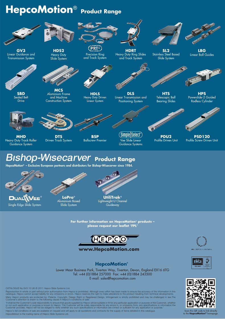
Lower Moor Business Park, Tiverton Way, Tiverton, Devon, England EX16 6TGTel: +44 (0)1884 257000 Fax: +44 (0)1884 243500
E-mail: [email protected]
HepcoMotion®
For further information on HepcoMotion® products – please request our leaflet ‘FPL’
UtiliTrak®
Lightweight U ChannelGuideway
MCSAluminium Frame
and Machine Construction System
Single Edge Slide System
Vee Slide LinearGuidance Systems
HepcoMotion®
LoPro®
Aluminium Based Slide System
Product Range
SL2Stainless Steel Based
Slide SystemPrecision Ring
and Track System
HepcoMotion® – Exclusive European partners and distributors for Bishop-Wisecarver since 1984.
Product Range
LBGLinear Ball Guides
HDRTHeavy Duty Ring Slides
and Track System
GV3Linear Guidance and Transmission System
®
HPSPowerslide-2 Guided
Rodless Cylinder
SBDSealed Belt
Drive
HDLSHeavy Duty Driven
Linear System
HTSTelescopic Ball Bearing Slides
DLSLinear Transmission and
Positioning System
BSPBallscrew Premier
MHDHeavy Duty Track Roller
Guidance System
PDU2Profile Driven Unit
PSD120Profile Screw Driven Unit
DTSDriven Track System
HDS2Heavy DutySlide System
Scan this QR code to link directly to the HepcoMotion® homepage.