Embed Size (px)
Citation preview

Hercules™ TMS570LS31x Microcontrollers
MibADC Example

2
Overview
• In this example we will:
– Create a TMS570LS31x HALCoGen Project
– Generate and import code into Code Composer Studio
– Write code to take analog to digital (ADC) conversions from the ambient
light sensor on the development board (USB Stick or HDK) and display
the conversion values to a PC using the SCI (UART) port.
– Build, deploy and execute the code to the microcontroller
• Required Hardware:
– Windows Based PC (WinXP, Vista, 7)
– TMS570LS31x USB Development Stick or TMS570LS31x Hercules
Development Kit
• Required Software:
– HALCoGen v2.11 or higher
– Code Composer Studio v4.x
00111011000100101
SCI/UART

3
• To launch HALCoGen go to:
– → Programs → Texas Instruments → Hercules → HALCoGen
Setting up a New HALCoGen Project
For more help with HALCoGen, see this getting started video: LINK

Setting up a New HALCoGen Project
4
• To create a new HALCoGen project:
– File → New → Project
• For the TMS570 USB Stick: – Choose Family: TMDX570LS31x
– Device:TMDX570LS31USB
• For the TMS570 HDK: – Choose Family: TMDX570LS31x
– Device:TMDXTMS570LS31HDK
• Then define a name: „ADC‟
• Location: “C:\myWorkspace”
1
3
2

5
Module Selection
• Drivers, Modules and Peripherals can be selected for configuration by either the
module selection ribbon or by clicking on the module in the block diagram
• The next step is to enable the appropriate drivers for this example
Ribbon
Block
Diagram
1

Enabling Perphierial Drivers
• Enable the SCILIN and MIBADC1 drivers in the „Driver Enable‟ sub tab of the
device
6
WARNING:
Make sure all other peripheral
drivers are disabled

ADC Group Configuration • From the MIBADC1 Group1 tab, configure FIFO Size, Trigger Source and ADC channel
as shown below
• Generate code: File → Generate Code or click
7
Only one conversion per software trigger is done
SW Trigger as Trigger Source
Ambient light sensor is connected to MibADC1 Pin9

Setting up Code Composer Studio 4 • Launch Code Composer Studio v4.x (CCS)
– Start → Programs → Texas Instruments → Code Composer Studio v4.x
→ Code Composer Studio v4
• When it launches, CCS will ask you to select a workspace, we will chose
“C:\myWorkspace”
• Once CCS loads, go to
File → New → CCS Project
8
WARNING:
Make sure to define the same
„Workspace‟ as defined in the
HALCoGen setup

Setting up the CCS Project
• Our project name needs to match the name of our HALCoGen Project: ADC
• Then Click “next”
• On the next page, make
sure that your project
type is set to ARM and
Debug and Release are
both checked
• Then Click “next”
9

Setting up the CCS Project
• We are not using any referenced projects so click “next” again
10

Setting up the CCS Project
• Next, set the Device Variant to “Cortex R”
11
• Choose: TMS570LS3137
• Device Endianness: be32
• Then click „Finish‟
1 2
3
4
• Expand the project and open the “sys_main.c” file from the CCS “Project Explorer”
Note: Since the HALCoGen and CCS project have the same project name, all the startup and driver
files generated by HALCoGen will be automatically included in the CCS project. Use the “sys_main.c”
file for your main program code.
Entering Code into the CCS Project
12

Entering Code into the CCS Project
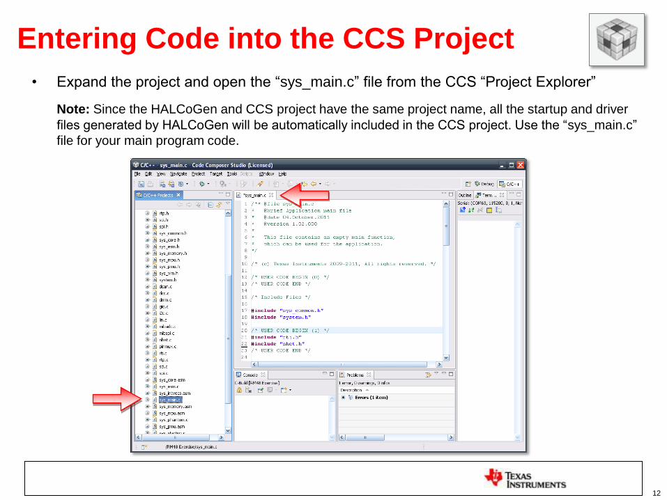
• Insert the following code in the corresponding sections within the „sys_main.c‟ file
– USER CODE BEGIN (0) - #include header section
13
/* USER CODE BEGIN (0) */
#include "sci.h"
#include "mibadc.h"
#include "stdlib.h"
unsigned char command[8];
/* USER CODE END */
– USER CODE BEGIN(3) - Main() section
14
void main(void)
{/* USER CODE BEGIN (3) */
mibadcData_t adc_data; //ADC Data Structure
mibadcData_t *adc_data_ptr = &adc_data; //ADC Data Pointer
unsigned int NumberOfChars, value; //Declare variables
sciInit(); //Initializes the SCI (UART) module
mibadcInit(); //Initializes the ADC module
while(1) // Loop to acquire and send ADC sample data via the SCI (UART)
{
mibadcStartConversion(mibadcREG1, 1U); //Start ADC conversion
while(!mibadcIsConversionComplete(mibadcREG1, 1U)); //Wait for ADC conversion
mibadcGetData(mibadcREG1, 1U, adc_data_ptr); //Store conversion into ADC pointer
value = (unsigned int)adc_data_ptr->value;
NumberOfChars = ltoa(value,(char *)command);
sciSend(scilinREG, 2, (unsigned char *)"0x"); //Sends '0x' hex designation chars
sciSend(scilinREG, NumberOfChars, command); //Sends the ambient light sensor data
sciSend(scilinREG, 2, (unsigned char *)"\r\n"); //Sends new line character
}
/* USER CODE END */}
Entering Code into the CCS Project

– USER CODE (4) - Interrupt notification section
15
/* USER CODE BEGIN (4) */
/* Notification functions not used, but required by compiler*/
void mibadcNotification(mibadcBASE_t *adc, unsigned group)
{
return;
}
void sciNotification(sciBASE_t *sci, unsigned flags)
{
return;
}
void esmGroup1Notification(int bit)
{
return;
}
void esmGroup2Notification(int bit)
{
return;
}
/* USER CODE END */
Entering Code into the CCS Project

Compiling the Project
• The code is now complete and we are ready to build our project.
– Go to Project → Build Active Project
• Now that we have our .out file, we need to program the microcontrollers Flash
memory.
16

Creating a Target Configuration
• Before we begin, we must make a new target configuration, this tells CCS4
what device this project is designed for.
– Target → New Target Configuration
17

Creating a Target Configuration
• A new window will appear, we will make our file name “Hercules MCU.ccxml”
• Click Finish
18

Creating a Target Configuration
• A new tab will appear with a list of emulators and devices.
– Connection: Texas Instruments XDS100v2 USB Emulator
• Click “Save” on the right
19
• Device General Setup: – In the „Device‟ box start typing
TMS570LS3 to filter the device list
– Select Device: TMS570LS3137
1
2
3
4

Flash Programming Configuration • It is possible to make the flash programming process much faster by only the
necessary erasing and programming the necessary regions of flash memory.
– To do so go to Project → Properties
– In the window that appears select „CCS Debug‟
– In the CCS Debug window select the TMS570LS3137 Flash Settings option
in the „Target‟ tab.
– Then select the „Necessary Sectors Only‟ option in the Erase Options area,
then click the „Apply‟ button.
NOTE:
This option
is only
available in
CCSv4.2
and newer
20
1 3 4
2

Programming the Flash
• We are now ready to program the flash.
– Go to Target → Debug Active Project
– A new window should appear as it programs the flash memory.
• This may take a few moments.
21
Testing your code
• Upon Completion open your preferred terminal program. – Note: A terminal program is included in CCSv4. To enable it go to „View‟ -> Other and select
„Terminal‟ from the „Show View‟ menu. (See the next page for more information).
• Setup the terminal program with the following properties:
– Baud rate: 9600
– Data bits: 8
– No parity, 2 Stop bits
22

Enabling the CCSv4 Terminal
1) Select View → Other
2) Then select „Terminal‟ from the „Show
View‟ menu.
3) Enter the proper communication
settings for the „Terminal Tab‟
23

24
Testing our Program • Click the green arrow on the debug tab to run our program
– Alternatively the program can be run without the debugger connected by
• Clicking the red square on the debug tab to terminate the debugger‟s connection
• Hit the reset button on the board and view the ADC data in the terminal. Use
the LED flashlight included with the TMS570 development kit to change the light
level supplied to the ambient light sensor on the board.
• Congratulations! You have completed the example.

25
For more HerculesTM TMS570 Information
TMS570 Web Page: www.ti.com/TMS570
– Data Sheets
– Technical Reference Manual
– Application Notes
– Software & Tools Downloads and Updates
– Order Evaluation and Development Kits
TMS570 Engineer 2 Engineer Forums:
www.ti.com/hercules-support
– News and Announcements
– Useful Links
– Ask Technical Questions
– Search for Technical Content
TMS570 WIKI:
www.ti.com/hercules-tms570-wiki
– How to guides
– Intro Videos
– General Information

26
Thank You!
For completing this TMS570 example