Embed Size (px)
Citation preview
HERZ 4017
Page 1
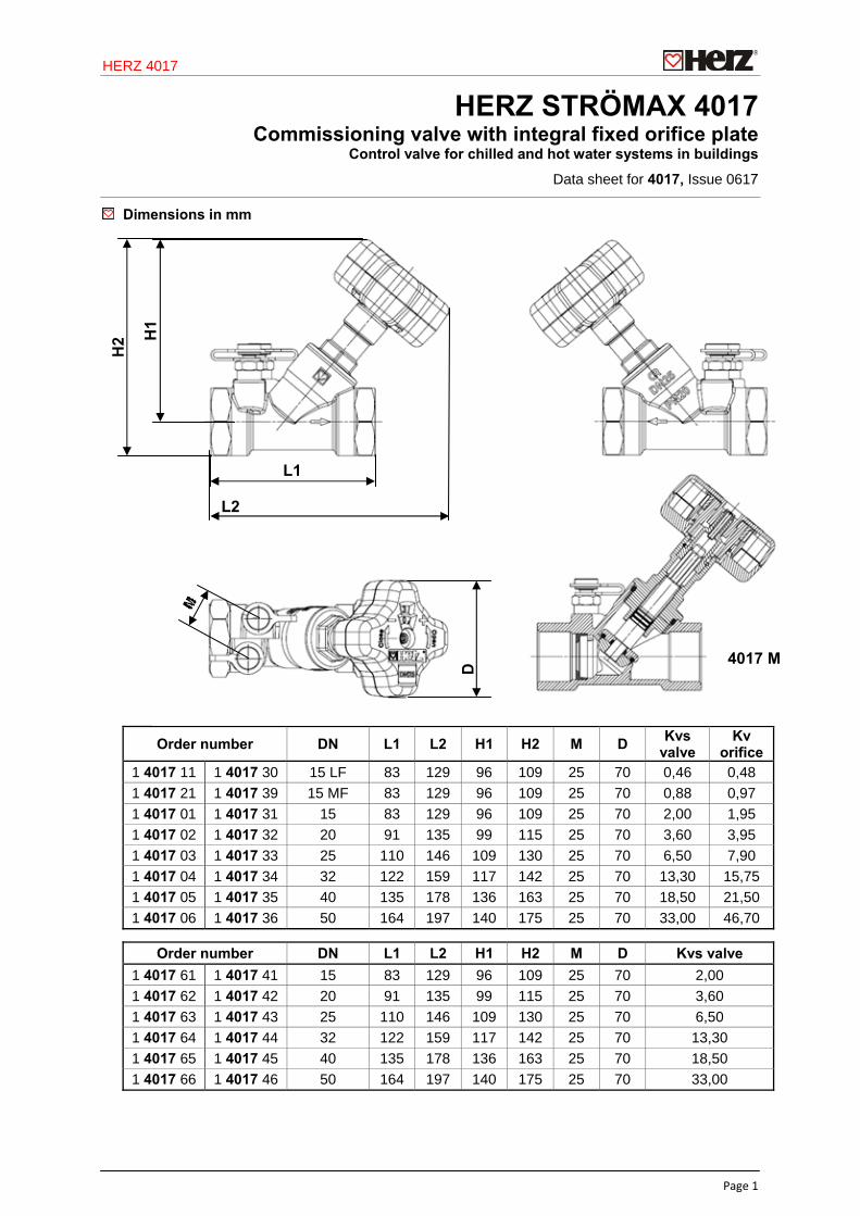
HERZ STRÖMAX 4017 Commissioning valve with integral fixed orifice plate
Dimensions in mm
Order number DN L1 L2 H1 H2 M D Kvs
valve Kv
orifice 1 4017 11 1 4017 30 15 LF 83 129 96 109 25 70 0,46 0,48
1 4017 21 1 4017 39 15 MF 83 129 96 109 25 70 0,88 0,97
1 4017 01 1 4017 31 15 83 129 96 109 25 70 2,00 1,95
1 4017 02 1 4017 32 20 91 135 99 115 25 70 3,60 3,95
1 4017 03 1 4017 33 25 110 146 109 130 25 70 6,50 7,90
1 4017 04 1 4017 34 32 122 159 117 142 25 70 13,30 15,75
1 4017 05 1 4017 35 40 135 178 136 163 25 70 18,50 21,50
1 4017 06 1 4017 36 50 164 197 140 175 25 70 33,00 46,70
Order number DN L1 L2 H1 H2 M D Kvs valve
1 4017 61 1 4017 41 15 83 129 96 109 25 70 2,00
1 4017 62 1 4017 42 20 91 135 99 115 25 70 3,60
1 4017 63 1 4017 43 25 110 146 109 130 25 70 6,50
1 4017 64 1 4017 44 32 122 159 117 142 25 70 13,30
1 4017 65 1 4017 45 40 135 178 136 163 25 70 18,50
1 4017 66 1 4017 46 50 164 197 140 175 25 70 33,00
4017 M
L1
L2
H1
H2
D
Control valve for chilled and hot water systems in buildings
Data sheet for 4017, Issue 0617
HERZ 4017
Page 2
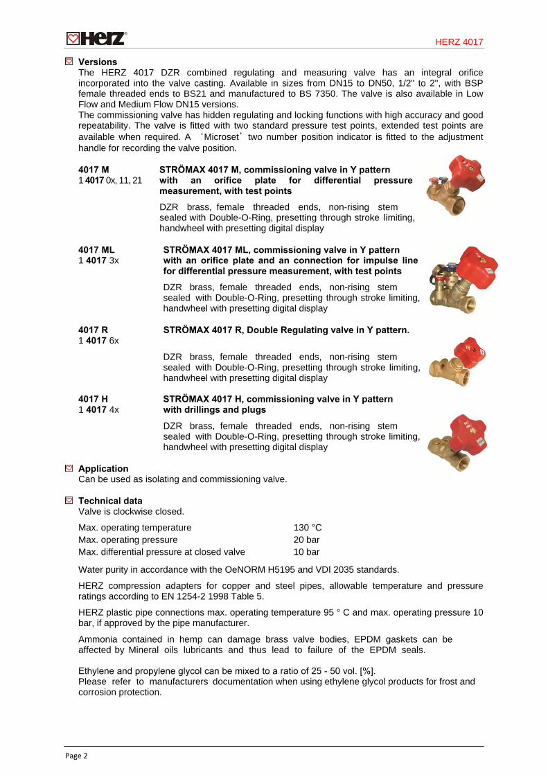
Versions The HERZ 4017 DZR combined regulating and measuring valve has an integral orifice incorporated into the valve casting. Available in sizes from DN15 to DN50, 1/2" to 2", with BSP female threaded ends to BS21 and manufactured to BS 7350. The valve is also available in Low Flow and Medium Flow DN15 versions. The commissioning valve has hidden regulating and locking functions with high accuracy and good repeatability. The valve is fitted with two standard pressure test points, extended test points are available when required. A ‘Microset’two number position indicator is fitted to the adjustment handle for recording the valve position.
4017 M STRÖMAX 4017 M, commissioning valve in Y pattern 1 4017 0x, 11, 21 with an orifice plate for differential pressure
measurement, with test points
4017 ML STRÖMAX 4017 ML, commissioning valve in Y pattern 1 4017 3x with an orifice plate and an connection for impulse line
for differential pressure measurement, with test points
4017 R STRÖMAX 4017 R, Double Regulating valve in Y pattern. 1 4017 6x
4017 H STRÖMAX 4017 H, commissioning valve in Y pattern 1 4017 4x with drillings and plugs
Application Can be used as isolating and commissioning valve.
Technical data Valve is clockwise closed.
Max. operating temperature 130 °C Max. operating pressure 20 bar Max. differential pressure at closed valve 10 bar
Water purity in accordance with the OeNORM H5195 and VDI 2035 standards.
HERZ compression adapters for copper and steel pipes, allowable temperature and pressure ratings according to EN 1254-2 1998 Table 5.
HERZ plastic pipe connections max. operating temperature 95 ° C and max. operating pressure 10 bar, if approved by the pipe manufacturer.
.
DZR brass, female threaded ends, non-rising stem sealed with Double-O-Ring, presetting through stroke limiting, handwheel with presetting digital display
DZR brass, female threaded ends, non-rising stem sealed with Double-O-Ring, presetting through stroke limiting, handwheel with presetting digital display
DZR brass, female threaded ends, non-rising stem sealed with Double-O-Ring, presetting through stroke limiting, handwheel with presetting digital display
DZR brass, female threaded ends, non-rising stem sealed with Double-O-Ring, presetting through stroke limiting, handwheel with presetting digital display
Ammonia contained in hemp can damage brass valve bodies, EPDM gaskets can be affected by Mineral oils lubricants and thus lead to failure of the EPDM seals.
Ethylene and propylene glycol can be mixed to a ratio of 25 - 50 vol. [%].Please refer to manufacturers documentation when using ethylene glycol products for frost and corrosion protection.
HERZ 4017
Page 3
Characteristics Flow direction The flow is observed according to the arrow on the body. There are no special tools required.
Installation In any orientation.
Setting The hand wheel position is indicated in the digital display readout on the top of the hand wheel, the valve set position can be locked easily by means of a concealed memory stop. The valve can be isolated and returned to the preset position at any time. The presetting is obscured by the hand wheel and protected against unauthorized operation.
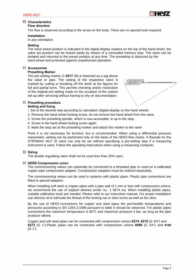
Accessories Presetting Marker The pre-setting marker (1 6517 05) is fastened as a tag above the valve or pipe. The setting of the respective valve is marked by cutting or breaking off the teeth at the figures for full and partial turns. This permits checking and/or restoration of the original pre-setting made on the occasion of the system set-up after servicing without having to rely on documentation.
Presetting procedure Setting and fixing 1. Set to the desired step according to calculation (digital display on the hand wheel). 2. Remove the hand wheel locking screw, do not remove the hand wheel from the valve. 3. Screw the presetting spindle, which is now accessible, in up to the stop. 4. Screw in the hand wheel locking screw again. 5. Mark the step set at the presetting marker and attach the marker to the valve
Point 5 is not necessary for function, but is recommended. When using a differential pressure manometer, setting can be performed only on the basis of the HERZ-flow charts. A flowrate for the STRÖMAX 4017 M valve can only be set without specifying a pre-setting step if a measuring instrument is used. Follow the operating instructions when using a measuring computer.
Sizing The double regulating valve shall not be used less than 25% open.
HERZ-Compression union The commissioning valves can optionally be connected to a threaded pipe or used on a calibrated copper pipe compression adapter. Compression adapters must be ordered separately.
The commissioning valves can be used in systems with plastic pipes. Plastic pipe connections are fitted to special adapters
When installing soft steel or copper pipes with a pipe wall of 1 mm or less with compression unions, we recommend the use of support sleeves (order no.: 1 0674 xx). When installing plastic pipes, suitable calibration tools are needed. Please refer to our instruction manual. For proper installation use silicone oil to lubricate the thread of the locking nut or olive screw as well as the olive.
By the use of HERZ-connections for cupper and steel pipes the permissible temperatures and pressures according to EN 1254-2:1998 pursuant to table 5 should be observed. For plastic pipes connections the maximum temperature is 80°C and maximum pressure 4 bar, as long as the pipe producer allows.
Copper and soft steel pipes can be connected with compression unions 6274, 6276 (G 3/4") and 6273 (G 1").Plastic pipes can be connected with compression unions 6098 (G 3/4") and 6198 (G 1").
HERZ 4017
Page 4
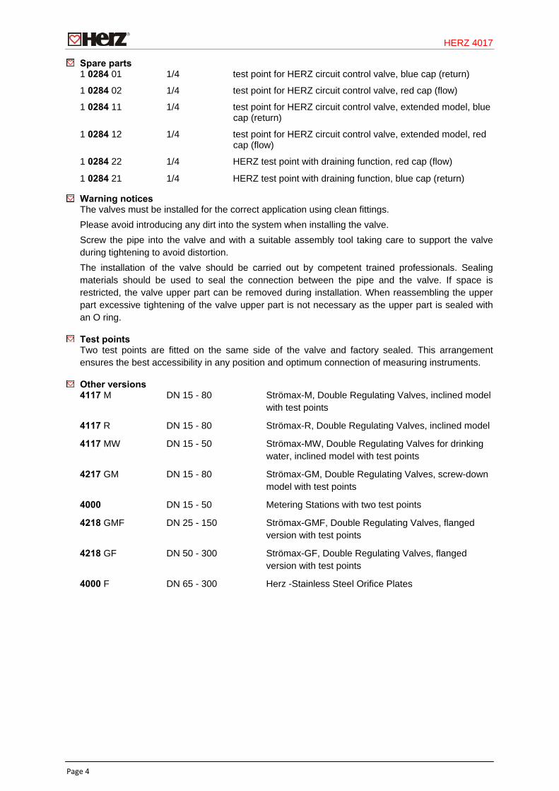
Spare parts 1 0284 01 1/4 test point for HERZ circuit control valve, blue cap (return)
1 0284 02 1/4 test point for HERZ circuit control valve, red cap (flow)
1 0284 11 1/4 test point for HERZ circuit control valve, extended model, blue cap (return)
1 0284 12 1/4 test point for HERZ circuit control valve, extended model, red cap (flow)
1 0284 22 1/4 HERZ test point with draining function, red cap (flow)
1 0284 21 1/4 HERZ test point with draining function, blue cap (return)
Warning notices The valves must be installed for the correct application using clean fittings.
Please avoid introducing any dirt into the system when installing the valve.
Screw the pipe into the valve and with a suitable assembly tool taking care to support the valve during tightening to avoid distortion.
The installation of the valve should be carried out by competent trained professionals. Sealing materials should be used to seal the connection between the pipe and the valve. If space is restricted, the valve upper part can be removed during installation. When reassembling the upper part excessive tightening of the valve upper part is not necessary as the upper part is sealed with an O ring.
Test points Two test points are fitted on the same side of the valve and factory sealed. This arrangement ensures the best accessibility in any position and optimum connection of measuring instruments.
Other versions 4117 M DN 15 - 80 Strömax-M, Double Regulating Valves, inclined model
with test points
4117 R DN 15 - 80 Strömax-R, Double Regulating Valves, inclined model
4117 MW DN 15 - 50 Strömax-MW, Double Regulating Valves for drinking water, inclined model with test points
4217 GM DN 15 - 80 Strömax-GM, Double Regulating Valves, screw-down model with test points
4000 DN 15 - 50 Metering Stations with two test points
4218 GMF DN 25 - 150 Strömax-GMF, Double Regulating Valves, flanged version with test points
4218 GF DN 50 - 300 Strömax-GF, Double Regulating Valves, flanged version with test points
4000 F DN 65 - 300 Herz -Stainless Steel Orifice Plates
HERZ 4017
Page 5
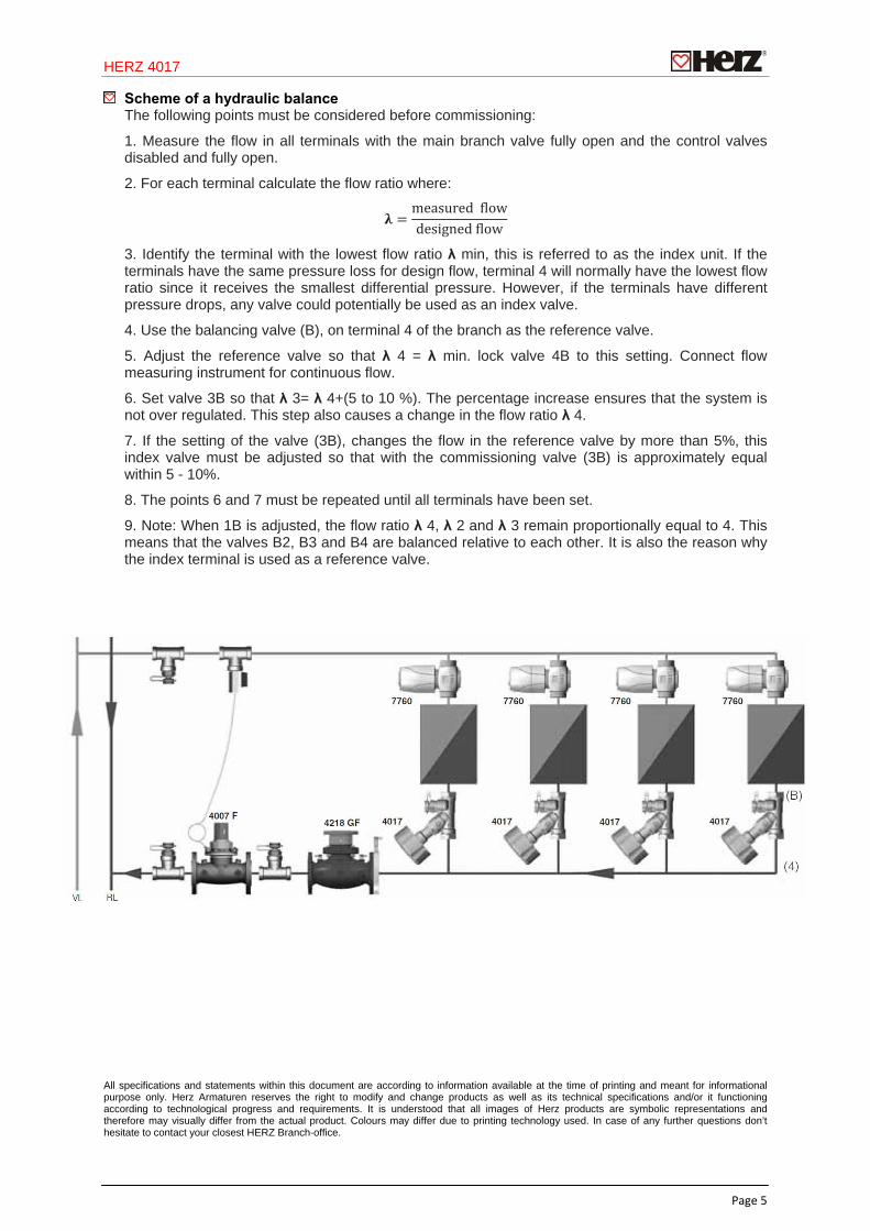
Scheme of a hydraulic balance The following points must be considered before commissioning:
1. Measure the flow in all terminals with the main branch valve fully open and the control valves disabled and fully open.
2. For each terminal calculate the flow ratio where:
measured lowdesigned low
3. Identify the terminal with the lowest flow ratio λ min, this is referred to as the index unit. If the terminals have the same pressure loss for design flow, terminal 4 will normally have the lowest flow ratio since it receives the smallest differential pressure. However, if the terminals have different pressure drops, any valve could potentially be used as an index valve.
4. Use the balancing valve (B), on terminal 4 of the branch as the reference valve.
5. Adjust the reference valve so that λ 4 = λ min. lock valve 4B to this setting. Connect flow measuring instrument for continuous flow.
6. Set valve 3B so that λ 3= λ 4+(5 to 10 %). The percentage increase ensures that the system is not over regulated. This step also causes a change in the flow ratio λ 4.
7. If the setting of the valve (3B), changes the flow in the reference valve by more than 5%, this index valve must be adjusted so that with the commissioning valve (3B) is approximately equal within 5 - 10%.
8. The points 6 and 7 must be repeated until all terminals have been set.
9. Note: When 1B is adjusted, the flow ratio λ 4, λ 2 and λ 3 remain proportionally equal to 4. This means that the valves B2, B3 and B4 are balanced relative to each other. It is also the reason why the index terminal is used as a reference valve.
All specifications and statements within this document are according to information available at the time of printing and meant for informational purpose only. Herz Armaturen reserves the right to modify and change products as well as its technical specifications and/or it functioning according to technological progress and requirements. It is understood that all images of Herz products are symbolic representations and therefore may visually differ from the actual product. Colours may differ due to printing technology used. In case of any further questions don’t hesitate to contact your closest HERZ Branch-office.
HERZ 4017
Page 6
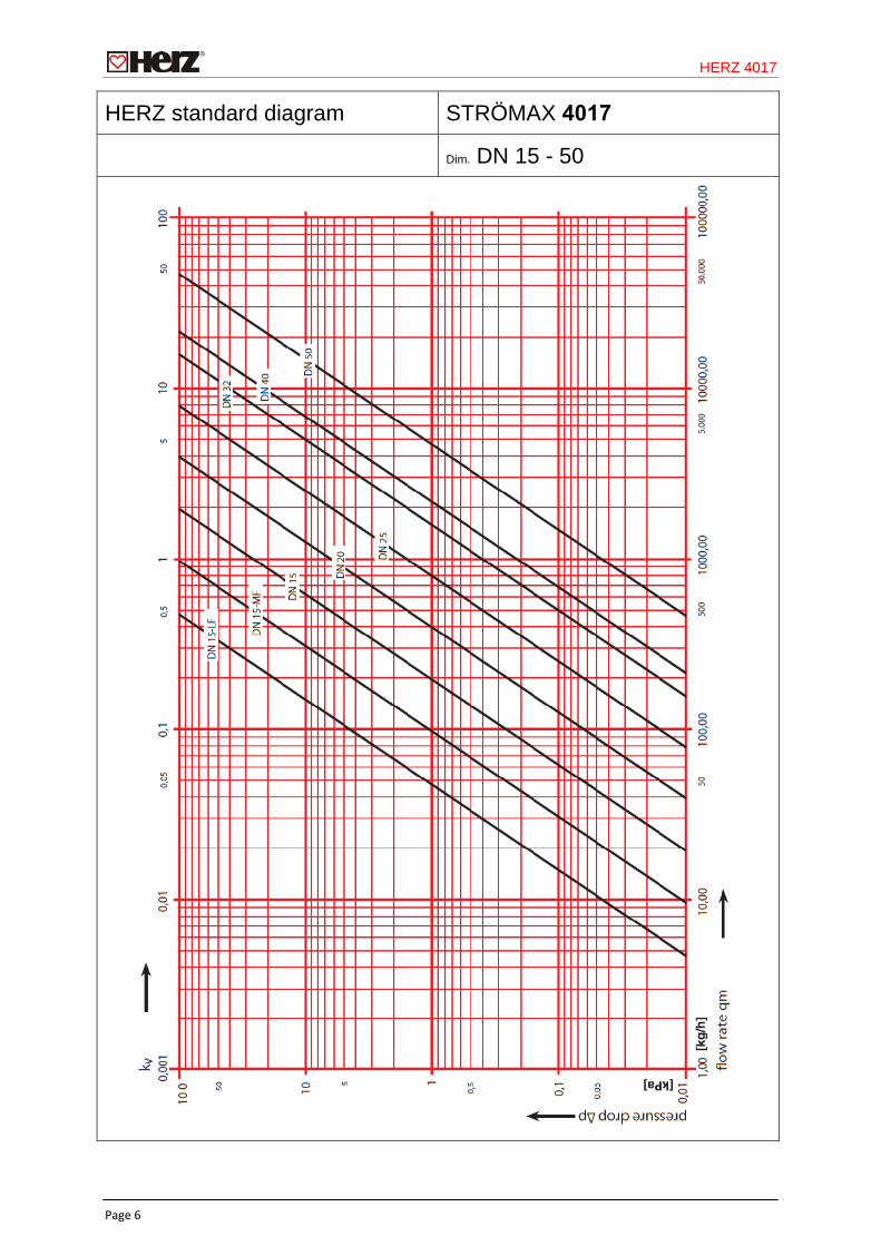
HERZ standard diagram STRÖMAX 4017
Dim. DN 15 - 50
HERZ 4017
Page 7
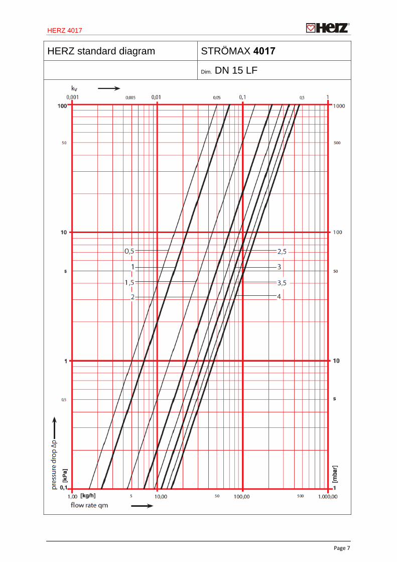
HERZ standard diagram STRÖMAX 4017
Dim. DN 15 LF
HERZ 4017
Page 8
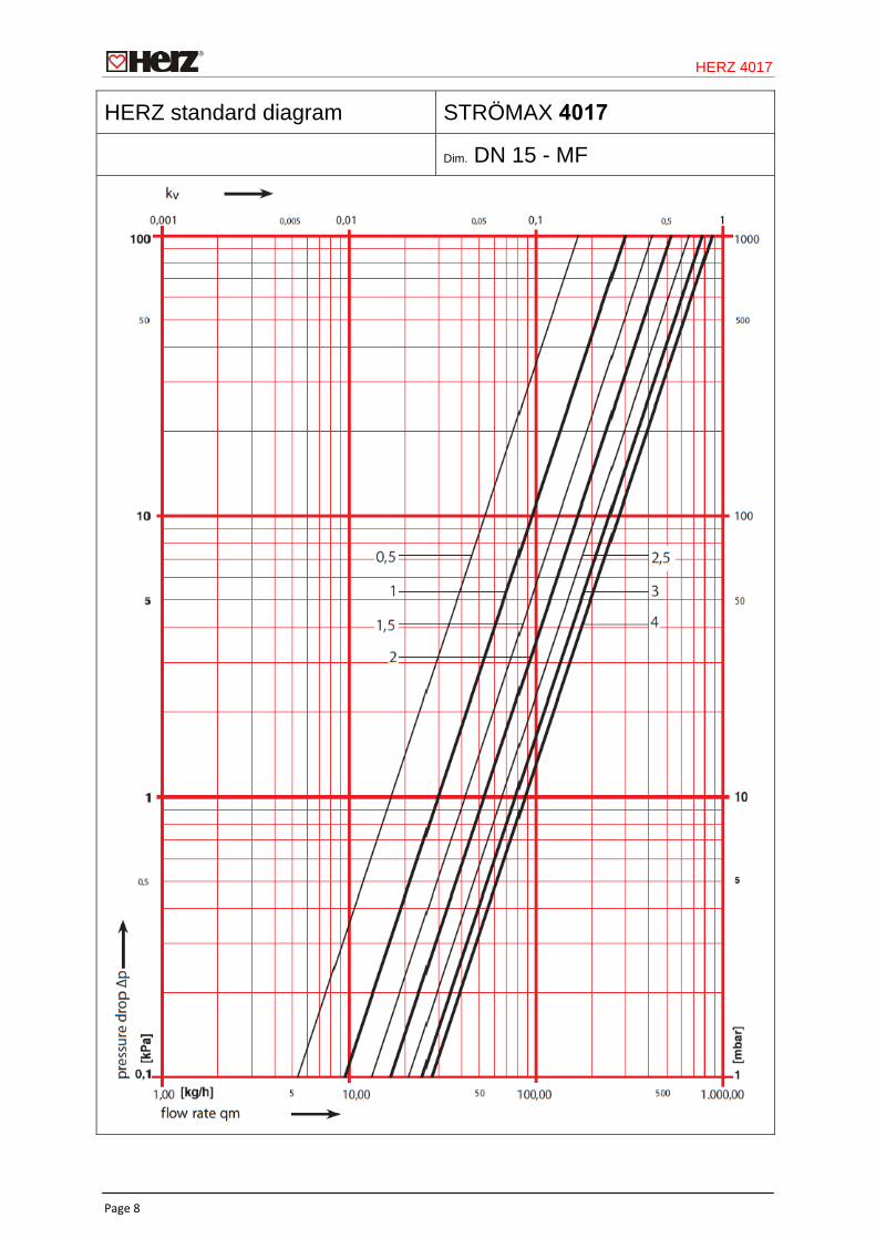
HERZ standard diagram STRÖMAX 4017
Dim. DN 15 - MF
HERZ 4017
Page 9
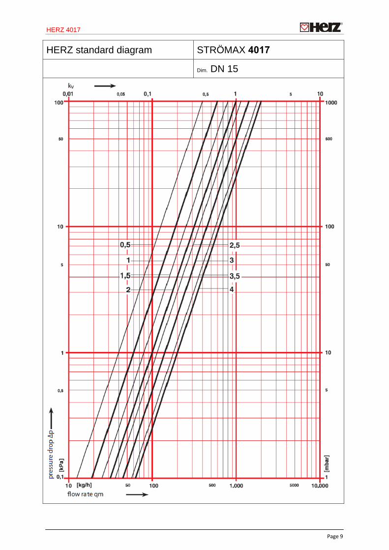
HERZ standard diagram STRÖMAX 4017
Dim. DN 15
HERZ 4017
Page 10
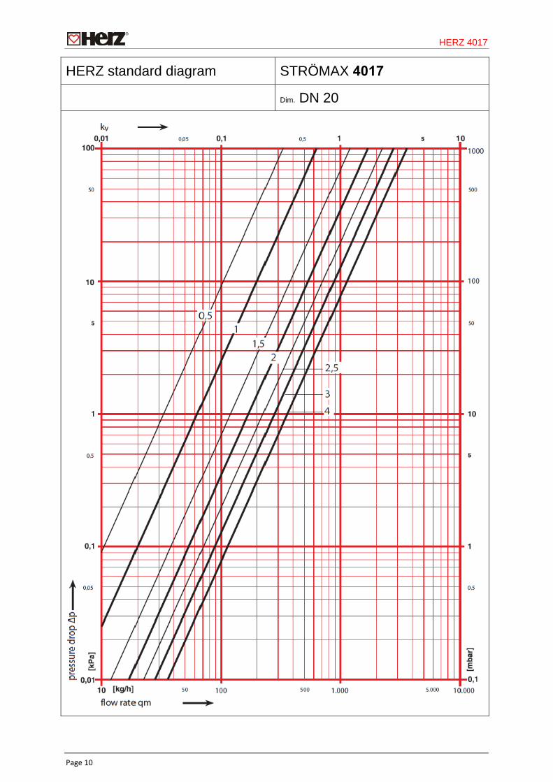
HERZ standard diagram STRÖMAX 4017
Dim. DN 20
HERZ 4017
Page 11
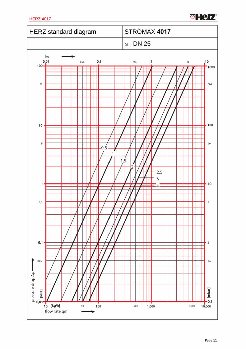
HERZ standard diagram STRÖMAX 4017
Dim. DN 25
HERZ 4017
Page 12
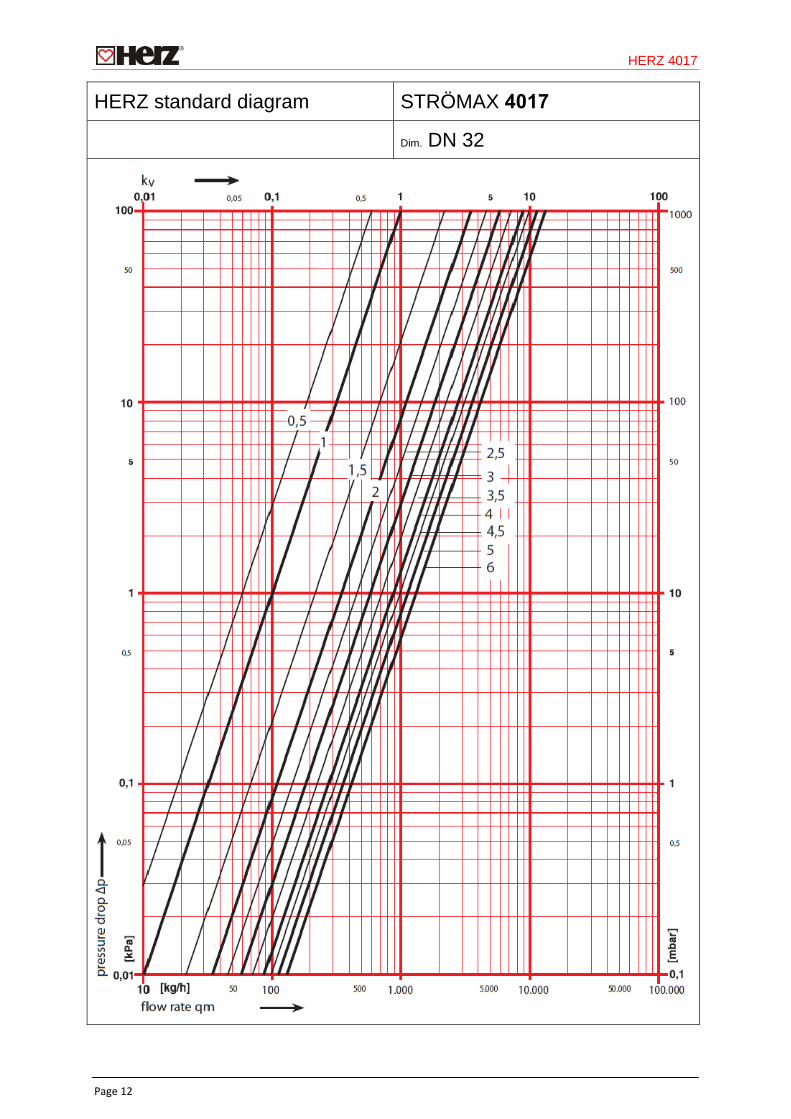
HERZ standard diagram STRÖMAX 4017
Dim. DN 32
HERZ 4017
Page 13
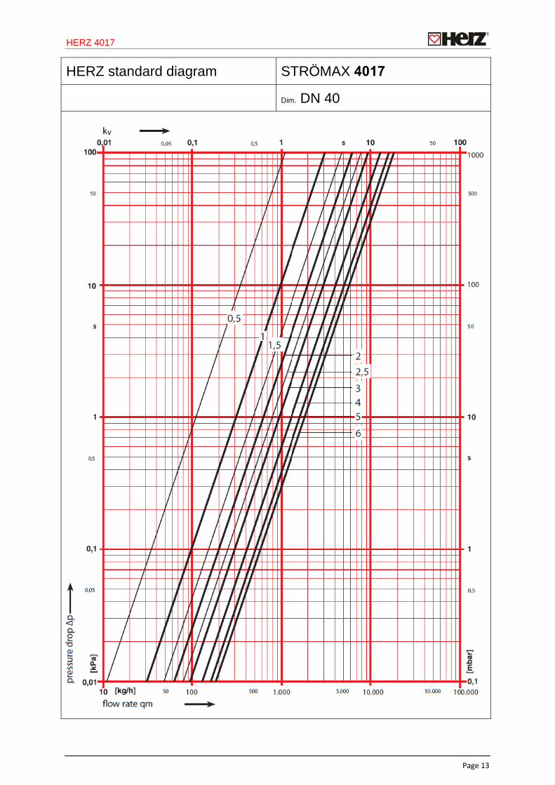
HERZ standard diagram STRÖMAX 4017
Dim. DN 40
HERZ 4017
Page 14
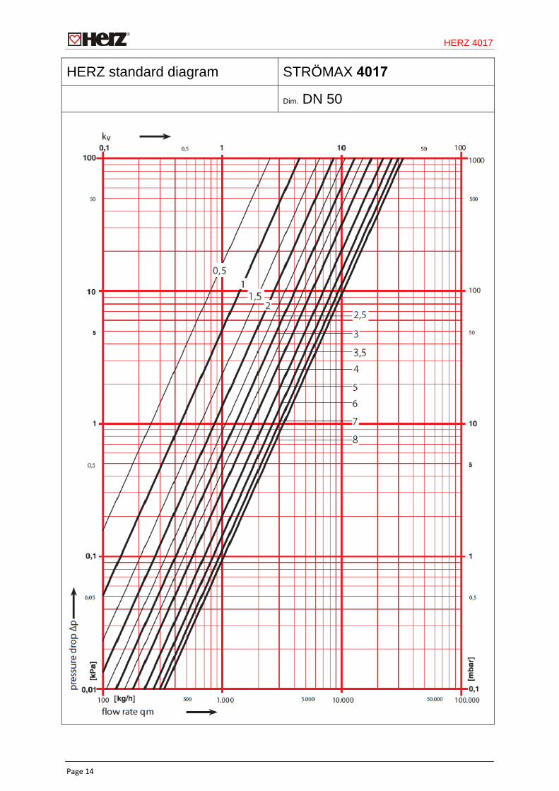
HERZ standard diagram STRÖMAX 4017
Dim. DN 50
HERZ 4017
Page 15
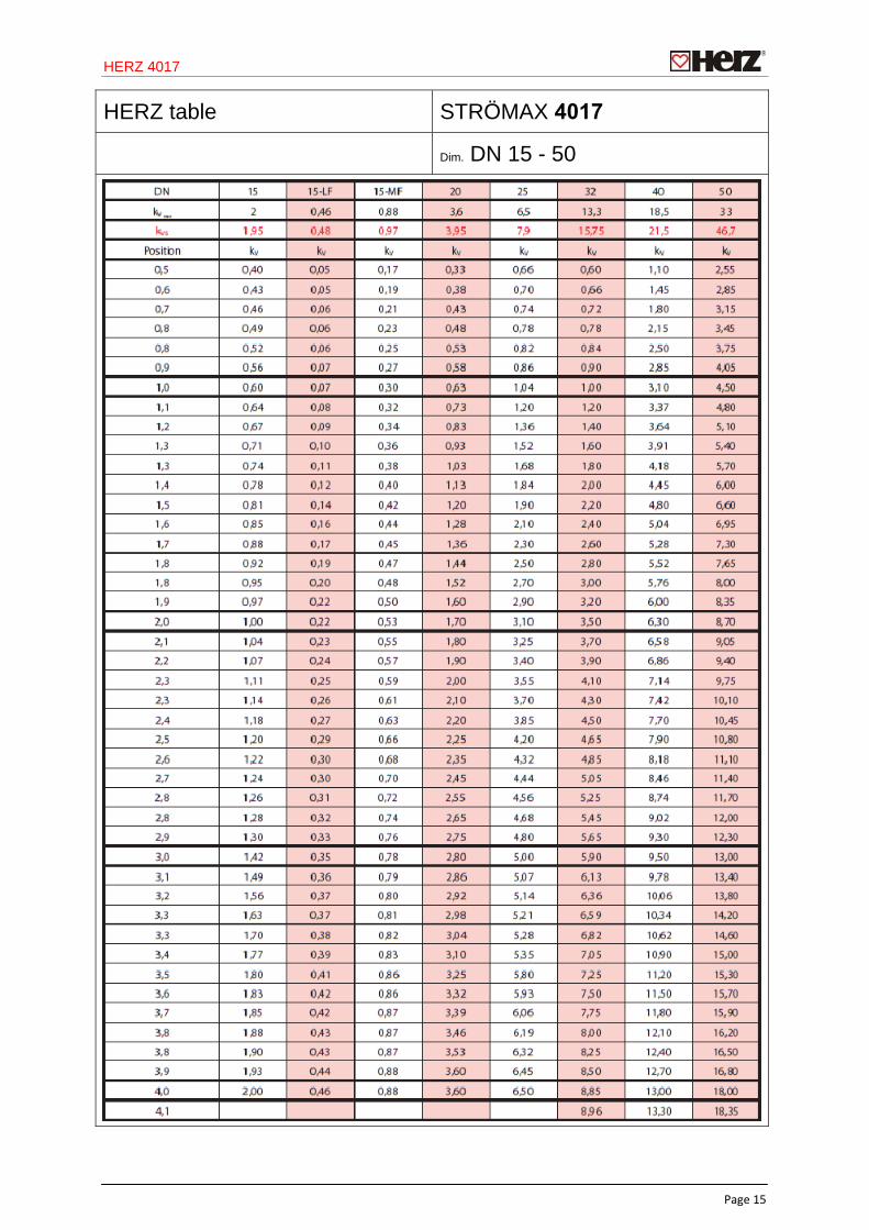
HERZ table STRÖMAX 4017
Dim. DN 15 - 50
HERZ 4017
Page 16
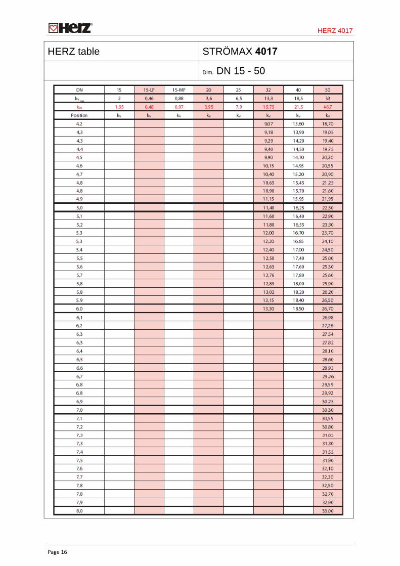
HERZ table STRÖMAX 4017
Dim. DN 15 - 50
HERZ 4017
Page 17
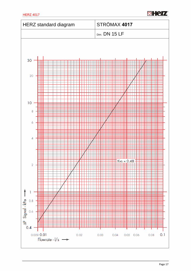
HERZ standard diagram STRÖMAX 4017
Dim. DN 15 LF
HERZ 4017
Page 18
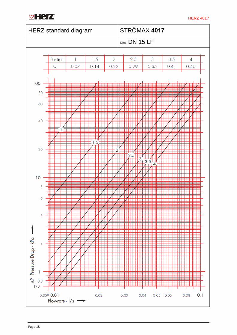
HERZ standard diagram STRÖMAX 4017
Dim. DN 15 LF
HERZ 4017
Page 19
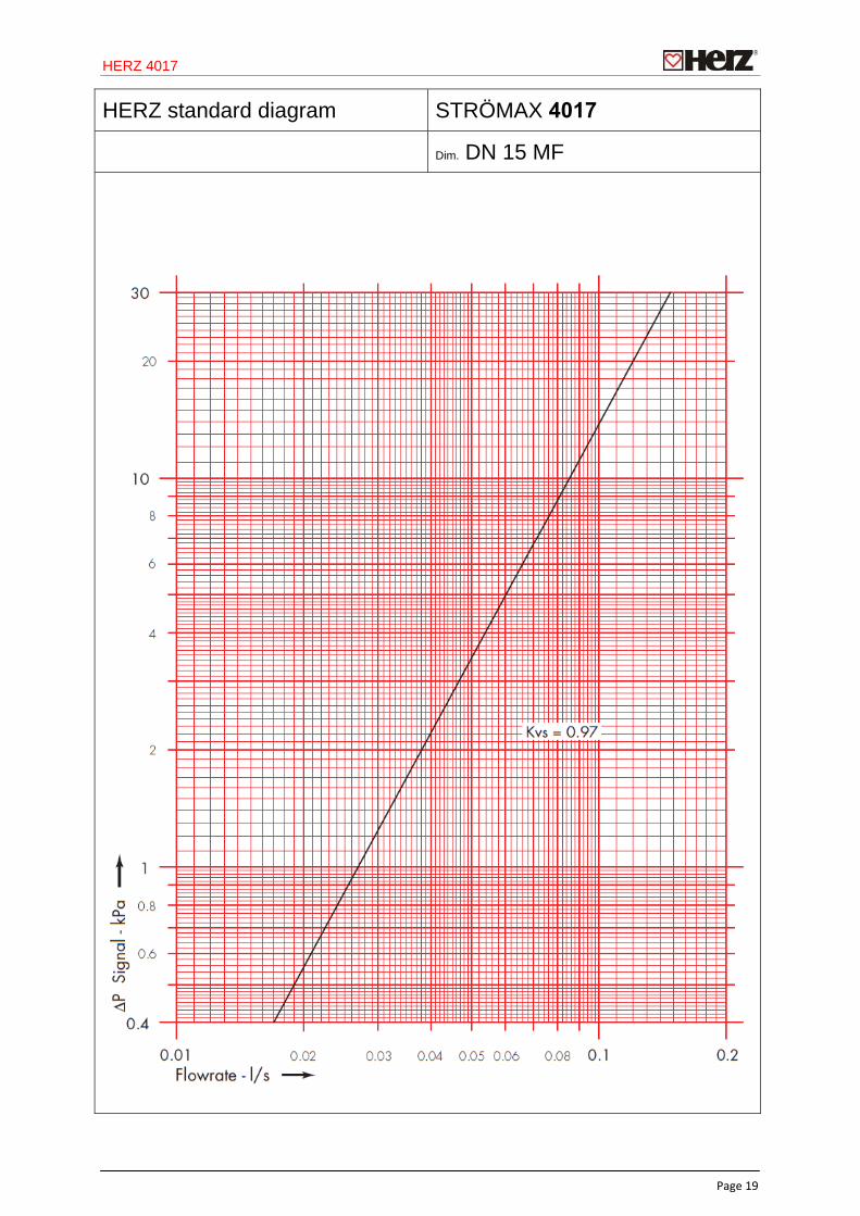
HERZ standard diagram STRÖMAX 4017
Dim. DN 15 MF
HERZ 4017
Page 20
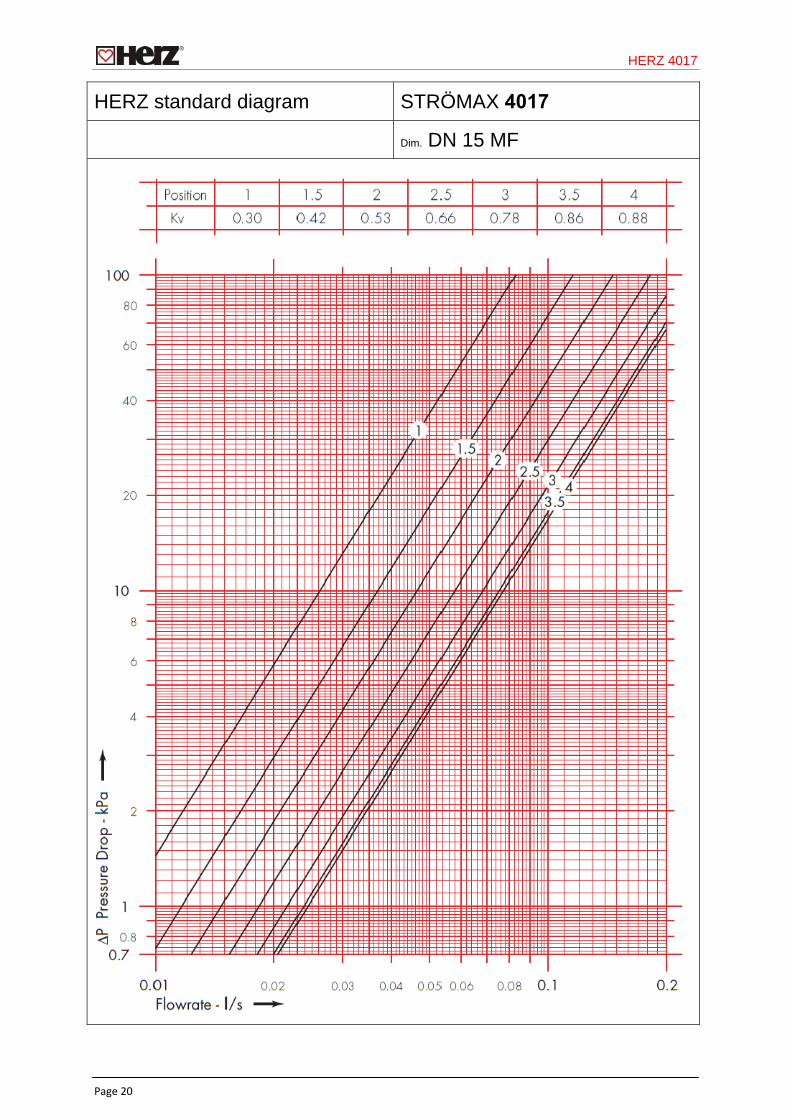
HERZ standard diagram STRÖMAX 4017
Dim. DN 15 MF
HERZ 4017
Page 21
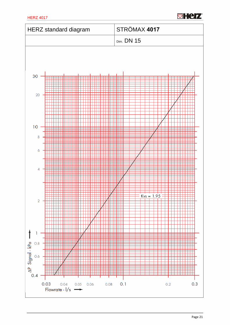
HERZ standard diagram STRÖMAX 4017
Dim. DN 15
HERZ 4017
Page 22
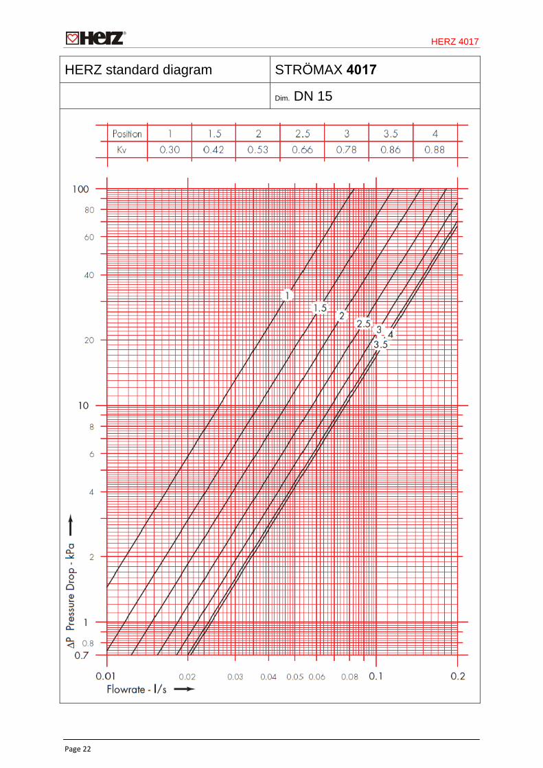
HERZ standard diagram STRÖMAX 4017
Dim. DN 15
HERZ 4017
Page 23
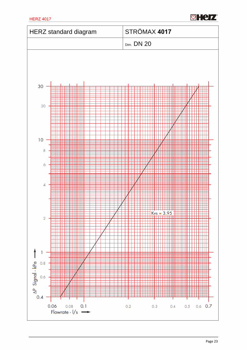
HERZ standard diagram STRÖMAX 4017
Dim. DN 20
HERZ 4017
Page 24
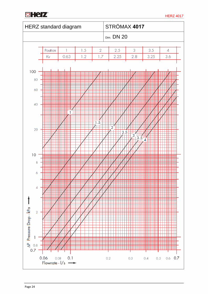
HERZ standard diagram STRÖMAX 4017
Dim. DN 20
HERZ 4017
Page 25
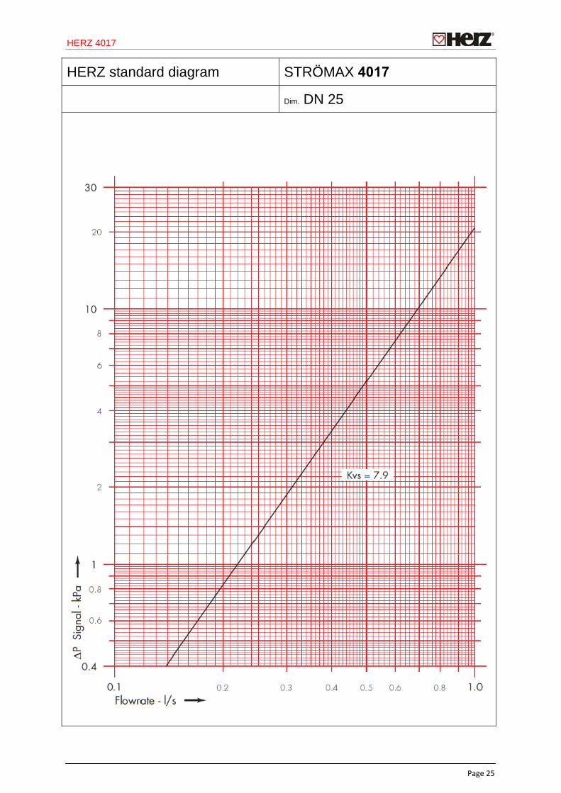
HERZ standard diagram STRÖMAX 4017
Dim. DN 25
HERZ 4017
Page 26
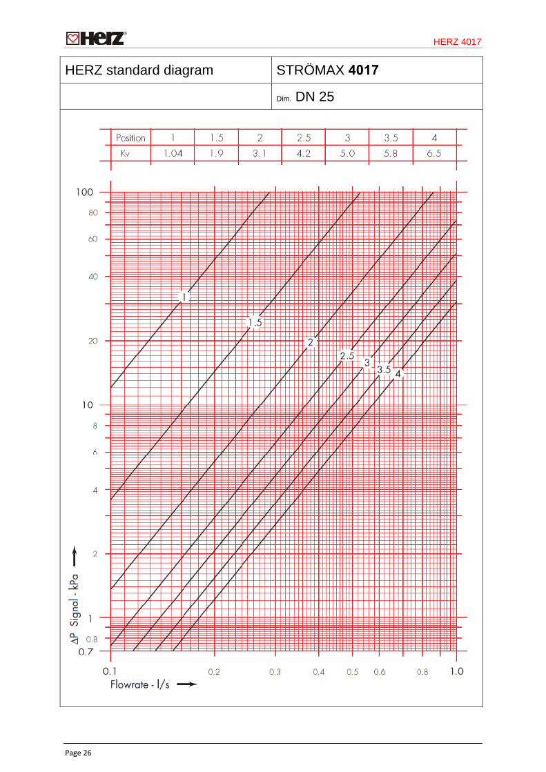
HERZ standard diagram STRÖMAX 4017
Dim. DN 25
HERZ 4017
Page 27
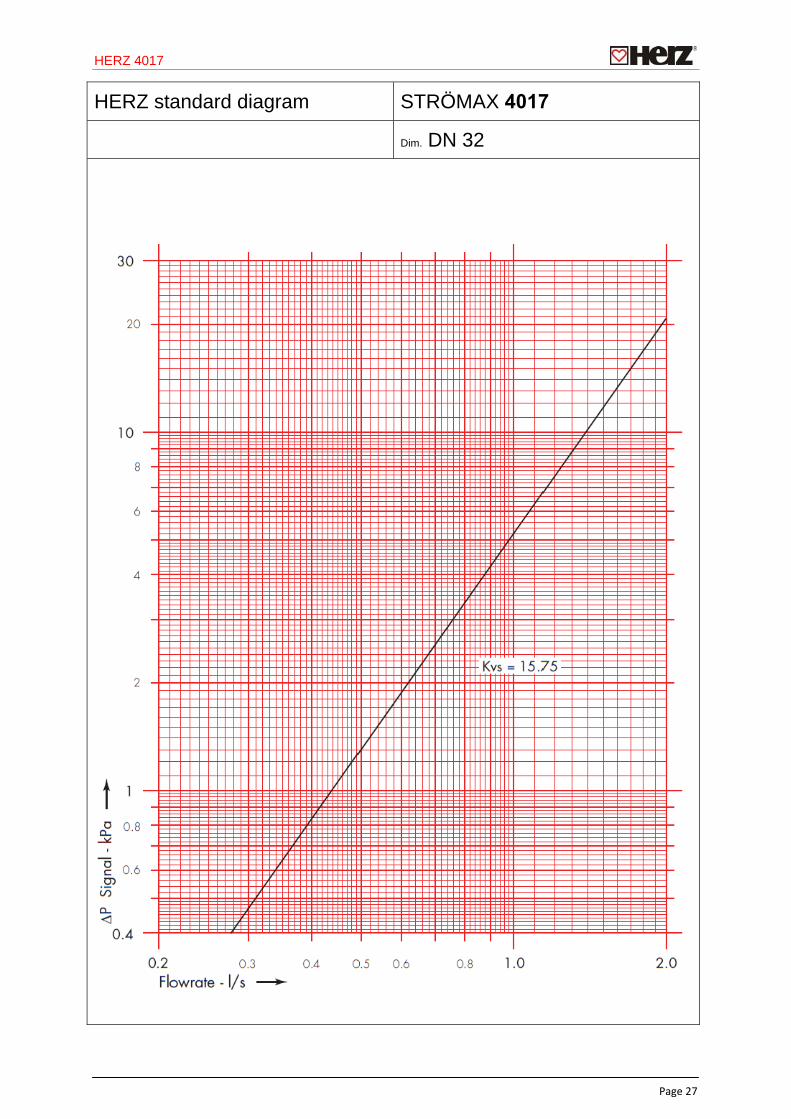
HERZ standard diagram STRÖMAX 4017
Dim. DN 32
HERZ 4017
Page 28
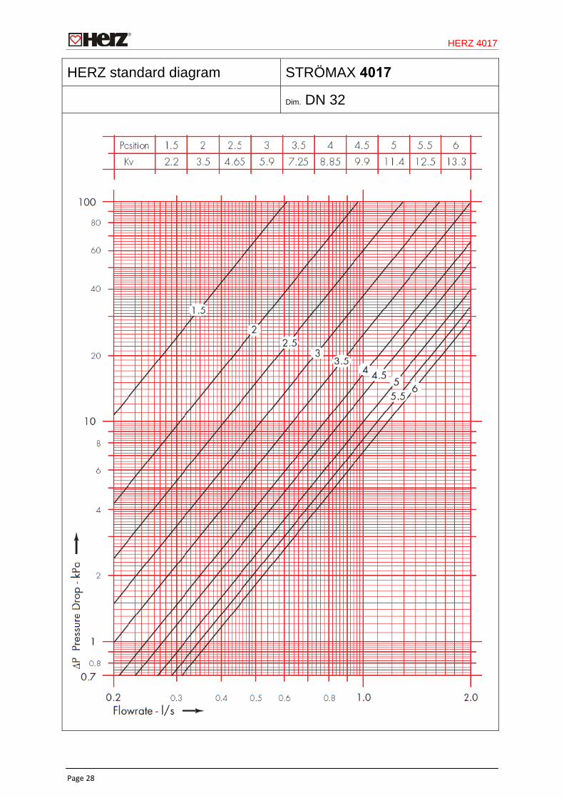
HERZ standard diagram STRÖMAX 4017
Dim. DN 32
HERZ 4017
Page 29
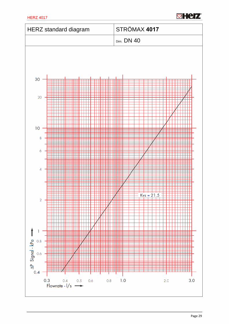
HERZ standard diagram STRÖMAX 4017
Dim. DN 40
HERZ 4017
Page 30
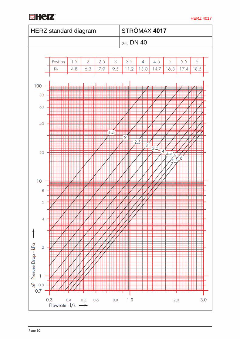
HERZ standard diagram STRÖMAX 4017
Dim. DN 40
HERZ 4017
Page 31
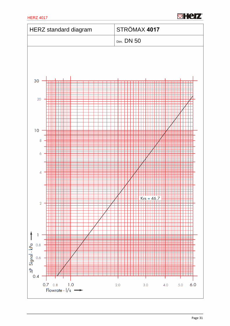
HERZ standard diagram STRÖMAX 4017
Dim. DN 50
HERZ 4017
Page 32
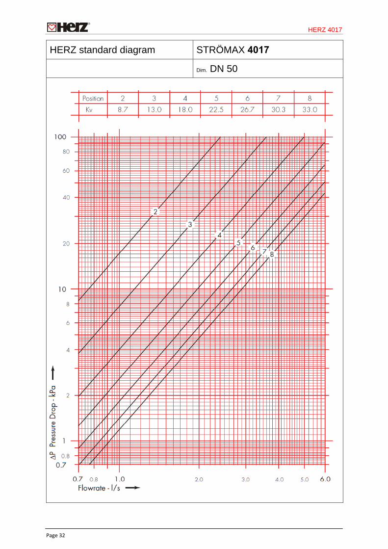
HERZ standard diagram STRÖMAX 4017
Dim. DN 50