Embed Size (px)
Citation preview

Technical report, IDE0935, May 2009
Heterogeneous Embedded Network
Architecture
Master’s Thesis in Computer Systems Engineering
Faisal Rehman
Supervisor: Magnus Jonsson
School of Information Science, Computer and Electrical Engineering Halmstad University

Heterogeneous Embedded Network Architecture
Master’s thesis in Computer Systems Engineering
School of Information Science, Computer and Electrical Engineering Halmstad University
Box 823, S-301 18 Halmstad, Sweden
May 2009

i
Preface This master’s thesis entitled Heterogeneous Embedded Network Architecture has been written for the partial fulfilment of the master’s degree in computer system engineering at Halmstad University, Sweden. I have greatly profited from hints, generously lavished in the course of correspondence, from my supervisor Professor Magnus Jonsson and I am very much thankful to him for his comments and guidance in this master’s thesis report. I would like to extend my sincere gratitude to my parents who always supported and encouraged me during my stay and study in Sweden. Last but not least, I would also appreciate moral support I have got from my fiancée who is always there to support me whenever I need her. Faisal Rehman Halmstad University, May 2009

ii

iii
Abstract In this thesis we focused on high performance embedded real-time networks which are designed for systems like radar signalling processing systems, control systems etc. These high performance embedded networks consist of emerging standards like PCI Express, RapidIO, and standard Ethernet. All of these switched embedded networks communicate with each other through common gateway nodes. As these networks have different rate characteristics, maximum packet size (MTU), packet priorities, addressing schemes etc we have therefore defined the gateway nodes for these heterogeneous embedded networks which will allow these heterogeneous embedded networks to communicate with each other with the help of different translation functions. These gateway nodes allow end-to-end transmission across the heterogeneous embedded networks while keeping bound on end-to-end delay and guaranteed throughput. We need to have some flow control mechanism which will shape the traffic flow in the mentioned embedded networks and will avoid from buffer overflow.

iv
Table of Contents
PREFACE ............................................................................................................................................... I
ABSTRACT ......................................................................................................................................... III
TABLE OF CONTENTS..................................................................................................................... IV
LIST OF FIGURES ...............................................................................................................................V
1 INTRODUCTION ......................................................................................................................... 1
1.1 MOTIVATION ........................................................................................................................... 1 1.2 GOAL AND APPROACH............................................................................................................. 2 1.3 NETWORK STANDARDS ........................................................................................................... 2
1.3.1 PCI Express ........................................................................................................................ 2 1.3.2 RapidIO .............................................................................................................................. 4 1.3.3 Ethernet .............................................................................................................................. 5
2 RELATED WORK........................................................................................................................ 7
3 GATEWAY NODE........................................................................................................................ 9
4 FRAGMENTATION....................................................................................................................12
5 ADDRESSING..............................................................................................................................16
6 TRAFFIC CLASS TRANSLATION ...........................................................................................20
7 END-TO-END DELAY ANALYSIS............................................................................................24
7.1 REAL-TIME TRAFFIC PARAMETERS AND COMMUNICATION SERVICE........................................24 7.2 DELAY ANALYSIS FOR HETEROGENEOUS NETWORK................................................................27 7.3 END-TO-END DELAY ANALYSIS FOR A HOMOGENEOUS NETWORK............................................29 7.4 END-TO-END FOR DELAY ANALYSIS FOR A WHOLE HETEROGENEOUS NETWORK......................34
8 FLOW CONTROL.......................................................................................................................36
8.1 FLOW CONTROL AT THE SOURCE NODE...................................................................................37 8.2 FLOW CONTROL AT THE GATEWAY NODE...............................................................................39
9 CONCLUSION.............................................................................................................................42
10 REFERENCES.............................................................................................................................43

v
List of Figures Figure 1: Heterogeneous Embedded Network..........................................................................................10
Figure 2: Fragmentation process from PCIe network to RapidIO network................................................13
Figure 3: RapidIO segments header fields ...............................................................................................13
Figure 4: Fragmentation process from RapidIO network to PCIe network................................................14
Figure 6: Fragmentation process from Ethernet network to PCIe network................................................15
Figure 7: Ethernet addressing scheme......................................................................................................16
Figure 8: PCIe to RapidIO address mapping............................................................................................17
Figure 9: PCIe to Ethernet address mapping............................................................................................18
Figure 10: PCIe to RapidIO traffic class translation.................................................................................21
Figure 11: RapidIO to PCIe traffic class translation.................................................................................21
Figure 12: PCIe to Ethernet traffic class translation .................................................................................22
Figure 13: Ethernet to RapidIO traffic class translation............................................................................23
Figure 14: RapidIO to Ethernet traffic class translation............................................................................23
Figure 15: Maximum buffer size at Time2...............................................................................................31
Figure 16: Network switch receiving traffic from source node as well other switches ..............................33
Figure 17: Jitter problem in a network.....................................................................................................37
Figure 18: Algorithm for source node......................................................................................................38
Figure 19: Double queue structure of Stop-and-Go queuing strategy .......................................................40
Figure 20: Single queue structure of Stop-and-Go queuing strategy.........................................................40


Introduction
1
1 Introduction In many distributed embedded systems where different parts of the system need to communicate with each other, real-time communication must be supported. Applications need real-time performance with bounded delay and high throughput in these embedded systems. Consequently, different parts of the system need to co-ordinate with each other with strict timing requirements [1]. These different parts of the embedded system can be referred to as networks which can be differentiated from the other networks on the basis of the technology used and the task assigned to them. Different emerging network interconnect standards are used in embedded systems for high throughput with low latency. These standards include PCI Express (PCIe), RapidIO, and the well known standard Ethernet. Each standard has its own features and performance level, therefore enabling researchers to come up with solutions which can bridge these heterogeneous network standards for real-time and reliable embedded systems. The focus of this thesis is to study the architecture of the heterogeneous embedded system consisting of switched networks like PCIe, RapidIO, and standard Ethernet. We need to study how we can have reliable and predictable communication between two nodes in a heterogeneous embedded network. There is a common point where these heterogeneous switched embedded networks need to interconnect with each other; we refer to this interface as the gateway node. We need to study this gateway node for different gateway operations which will occur during heterogeneous embedded network communication between end nodes. Some such gateway operations include fragmentation, traffic translation, and addressing. At the same time we also need to analyse end-to-end delay and flow control mechanisms for communication in a heterogeneous embedded network. In the remaining part of this chapter we will explain the main ideas behind this thesis work, goal and approach that we will follow for our thesis report. Finally we will explain each of the network standards which will be used in our heterogeneous embedded network architecture. In chapter 2 we will discuss some related work to our thesis. We will discuss gateway node and possible gateway node operations for our heterogeneous embedded network architecture in chapter 3. Some of the gateway node operations include fragmentation, addressing, and traffic class translation which we will cover in chapter 4, chapter 5, and chapter 6 respectively. In chapter 7 we will analyse end-to-end delay for our heterogeneous embedded network. Finally in chapter 8 we discuss flow control mechanism which can be used for our heterogeneous embedded network architecture.
1.1 Motivation An embedded system may consist of boards, chips, other devices, and chassis. These components of the embedded system need real-time high performance communication with low latency,

Heterogeneous Embedded Network Architecture
2
bounded delay and high throughput. Having an eye on the performance parameters like low latency, bounded delay and high throughput, new emerging embedded network standards are often preferable to use in embedded system which can give high performance. Novel emerging switched embedded network standards result in the formation of the heterogeneous embedded networks in an embedded system. Thus methods and solutions are needed which will bridge these novel standards so we can have high performance real-time reliable communication in heterogeneous embedded network systems.
1.2 Goal and Approach In this thesis work we have carried out a case study on how communication take place in a heterogeneous embedded network system, consisting of PCI Express, RapidIO, and Ethernet networks seeking guaranteed performance. The goal with the case study has been to investigate necessary functions in the gateway nodes between different networks and to propose a solution to support guaranteed end-to-end real-time communication. Different operations we have studied for the gateway nodes include: Fragmentation, addressing, traffic class translation and flow control mechanism at the gateway nodes as well as at the source nodes. Further on, we have studied how to incorporate real-time analysis to be able to guarantee end-to-end delay performance.
1.3 Network Standards In this section we will provide an overview of different embedded networks standards which we will study in this thesis report. These embedded network standards consist of PCI Express, RapidIO, and standard Ethernet. Subsequently we will study each standard’s architecture, communication, priority support, routing etc so that it becomes easier to understand the whole heterogeneous embedded network architecture.
1.3.1 PCI Express PCI Express (PCIe) provides higher bandwidth than legacy PCI Interconnect and is compatible with existing operating systems. PCI Express works as a switched serial connection instead of bus network in legacy PCI. It has a switch which helps devices in data transfer in many point-to-point serial connections. All the devices have their own dedicated paths on which data can be transferred without bandwidth sharing. PCIe uses the same protocol used by PCI for identification of plugged-in devices and connections [2].

Introduction
3
PCIe architecture The PCIe architecture kept the legacy PCI architecture so that all existing applications and drivers operate unchanged. PCIe consists of five layers: Config/OS, S/W, Transaction, Link and Physical layer. We will describe the latter three layers. In [2] the author had explained the Config/OS and S/W layers. Physical layer
The physical layer is responsible for transportation of packets between the link layers of two PCIe agents.
Link layer The link layer is responsible for reliable delivery of the packet across the PCIe link. The checksum and sequencing of the packets to the transaction layer is issued by link layer. Transaction layer PCIe uses packets for transmission of data using the transaction layer. Apart from other header information in the packet there are values like unique identifier and traffic class in each packet which helps the packets to be properly served in switched networks.
Communication PCIe uses packets for transmission of data in a switched network. The packet’s header has source address, destination address, priority, etc information so that it can be routed in a network. The PCIe standard allows packets with maximum payload size of 4096 bytes for data transmission between end-nodes. Routing The PCIe standard supports 16-bits Device ID based routing scheme [4]. From the address in the packet header the switch determines whether it is the intended recipient; if so, then it will accept the packet and will check in the routing table to map the address to Device ID # (16 bits) and then forward the packet to appropriate node.

Heterogeneous Embedded Network Architecture
4
Priority PCIe packet has a 3-bits field defined for Traffic Class (TC) [4] which is used for the differentiation of transactions into eight traffic classes. These eight traffic classes (0-7) have 0 as the lowest priority traffic class while 7 is the highest traffic class. PCIe transaction layer packet uses TC information for proper serving the packet while traversing across the fabric. This information is also used at the gateway for proper serving of the traffic. Traffic serving differentiation is commonly achieved with the use of TC and virtual channel (VCs) mapping.
1.3.2 RapidIO RapidIO is an open standard packet-switched fabric technology, compatible with future needs. Among other well known leading companies in the field of embedded systems, Motorola is the leading company in taking interest in the RapidIO. It was designed for high performance networks by connecting processors, memory banks and other devices, chip-to-chip or board-to-board. It provides reliability, increased bandwidth and faster bus speed in an intra-system interconnection. Architecture The RapidIO protocol mainly consists of three layers: logic layer, transport layer and physical layer. Logical layer contains message passing, version-suited and cache-coherent shared memory. At the transport level, routing information is addressed, i.e. how a packet will move from one endpoint to another. The physical layer deals with device level interface, such as electrical characteristic, packet transport mechanism, coding and error handling [3]. The RapidIO architecture varies and depends upon different endpoints (processors, memories, bridges and I/O units) and switching nodes. With the help of the switch, packets can be sent across fabrics from one endpoint to other endpoints [7]. Communication RapidIO uses packets for communication between nodes in a network [7]. The packets have header information which contains source, and destination addresses, priority, etc for proper handling of packets at the gateway nodes if the packet is going to move across in a heterogeneous network. RapidIO standard allows up to 16 packets with maximum payload data of 256 bytes to form a message with a size of 4096 bytes in a heterogeneous network communication.

Introduction
5
Routing RapidIO performs device identifier (Device ID) based packet routing [3]. Each directly addressable device in the embedded system will have one unique device identifier. The multicast specification provides a mechanism to use unique RapidIO device IDs to allow switches to identify each node uniquely in a network. Each switch has a routing table which helps packets to reach their respective destinations and thus the switch elaborates packets to any set of one or more of their output ports. Priority RapidIO packets have 2-bits priorities defined in the “prio field” of the packet header and carries four possible values: 0, 1, 2, or 3. The “prio field” carrying value 0 shows the lowest priority value and the “prio field” carrying value 3 shows highest priority value [3] [7] . These priority values can be used while serving packets at the gateway node in a heterogeneous network communication.
1.3.3 Ethernet
Ethernet is the most popular LAN standard and is standardized as IEEE 802.3. To the best of our knowledge, to date the IEEE has not released any documented research paper for IEEE 802.3ap backplane Ethernet for embedded systems. Therefore, in this thesis report we will consider standard Ethernet for our heterogeneous embedded network architecture. Architecture In [9] the author defines Ethernet in terms of the following three layers for an embedded network. Logical layer According to the Ethernet specification, the Ethernet is defined up to layer 2 in the OSI stack. For an embedded network, the logical layer defines a general layer specification for those applications which are normally defined on top of layer 2 with reference to OSI layer model. For example: IP (layer 3), UDP (layer 4), TCP (layer 4).
Transport layer (Mac layer)
The transport layer defines the path for a packet which it will follow from source to destination in a given embedded network. Ethernet uses a destination-based addressing scheme with the help of

Heterogeneous Embedded Network Architecture
6
using 48 bits MAC address. In switched Ethernet, endpoints are connected by a switch. The switch has a routing table consisting of MAC addresses of nodes. The switch uses this routing table when traversing a packet towards its destination.
Physical layer
The physical layer defines the physical characteristics of Ethernet. It consists of a link protocol and the electrical interface between devices. The function of the link protocol is to move packets from one side to the other side of the link. The receiver uses an FCS field in each packet, defined in Ethernet, to verify the frame integrity. Communication Ethernet uses frames for communication between nodes in an Ethernet-based network. The frames have header information which contains source, and destination addresses, priority support, etc for proper handling of packets at the gateway nodes if the Ethernet frame is going to move across the heterogeneous network. The Ethernet frame supports a maximum payload size of 1500 bytes for data transmission.
Priority The IEEE 802.1D queuing feature enables layer 2 prioritization of traffic. The Ethernet frame contains two fields: Tag Protocol Identifier (TPID) and Tag Control Information (TCI). If the TPID field value in Ethernet is 8100, then this frame carries the tag IEEE 802.1 D/Q. The TCI field has a 3-bit priority field which can be used for up to eight classes of service.

Related work
7
2 Related work Switched Ethernet is a widely used technology these days in Local Area Networks. It was considered that the Ethernet standard does not have any support for high speed real-time applications. Then the breakthrough came in 1998 when [11] gave a novel solution by providing “Ethe-Real ” which does not need any hardware modification in switches as well as at the end nodes and still provides real-time support for real-time applications. Ethe-Real was well suited for throughput-oriented applications but it lacks bound on end-to-end delay for real-time applications which required guaranteed throughput with bounded end-to-end delay. In order to have bound on end-to-end delay as well as also having high throughput for hard real-time applications it was later found in [12] that the collision probability that was caused by the soft real-time application can be eliminated if we facilitate Ethernet switches with point-to-point virtual links between any two end nodes. Although [12] analysed switched Ethernet by using earliest deadline first scheduling (EDF), we will use the FIFO scheduling algorithm when analysing end-to-end delay bound for our heterogeneous embedded network, since this is what we can expect the switch chips to support. In [13], the authors discussed real-time communication support in a heterogeneous network which composed of connection-oriented FDDI-ATM-FDDI networks. They proposed a connection admission control algorithm, known as CAC, which will work in this heterogeneous network. According to CAC algorithm when a new connection request for connection establishment in the heterogeneous network then this CAC algorithm will perform admission control process and it will check whether the worst-case delay of the requesting and also the existing channel can be fulfilled. If it is satisfied then CAC makes and allocates sufficient bandwidth to the requesting new connection. Taking similar concepts we will analyse end-to-end delay for connections in heterogeneous embedded networks which are composed of PCI Express, RapidIO and Ethernet switched networks. In [14], the authors explained the process of encapsulation when an Access Point (AP) bridges traffic from wired Ethernet to IEEE 802.11 frame format in order to send the data in a wireless network. The packet header of IEEE 802.11 frame contains four address fields. In the encapsulation process the source and destination MAC addresses of wired Ethernet packet are copied to the source and destination of the 802.11 MAC header, respectively. One address field of 802.11 MAC header will contain the MAC address of AP whereas final address field is not used. The data portion of Ethernet from 802.2 LLC will be encapsulated and copied to the 802.11 frame format. This method of encapsulation of data between heterogeneous networks can be used for our heterogeneous embedded networks when we deal with addressing between two nodes that belongs to heterogeneous networks.

Heterogeneous Embedded Network Architecture
8
Another problem regarding addressing in a heterogeneous network is discussed in [15] where the authors address the problem of addressing in heterogeneous networks composed of networks such as PSTN/ATM, PSTN/IP, and ATM/IP. The problem of addressing happens when a node transmits a packet from type1 network and is destined for another node of similar type1 network. This end-to-end transmission of packets passes through another network of type2. Then the packet needs to have the knowledge about type2 address space to route the packet to its ultimate destination. As a solution to the mentioned addressing problem, the authors give some solutions. In the first solution they proposed that type1 address can be mapped to type2 address at the gateway node. Furthermore in the second solution they proposed the idea that the gateway node should be intelligent enough to determine type2 address from type1 destination address to route the packet towards destination node in type1 network. In [16], the author discussed different work-conserving and nonwork-conserving disciplines. In nonwork-conserving discipline the author discussed the problem of jitter which might occur during transmission of packets in multi-hop packet-switched networks. As a solution to the jitter problem the author proposed that the packets can be delayed for some time even if the server is idle during a certain time period. For this reason he proposed a general framework for nonwork-conserving discipline known as rate-controlled service discipline. It has two components, a rate controller and a scheduler. The rate controller consists of a regulator which will shape the packets while the scheduler will schedule the eligible packets coming from the regulator. This general framework allows us to have different combinations of regulators and schedulers which depend upon the network architecture. We can use similar framework for our heterogeneous embedded network by implementing Leaky bucket [19] or similar algorithm as a regulator followed by a FIFO scheduler.

Gateway node
9
3 Gateway node Two nodes communicating with each other belonging to different networks, having different network standards, can face many problems in a system. Each network will have its own protocols for communication between two nodes [7]. These networks can differ in a variety of ways:
• Each network may have different MTU (Maximum Transfer Unit) packet size, therefore, there is a need for fragmentation and reassembly function.
• Each network has different addressing schemes, therefore, we need a global memory addressing scheme which will have the address of every node in the heterogeneous embedded network.
• Each network has different traffic classes defined for a given packet, therefore, we need translation of different traffic classes between different networks.
• Flow control and congestion control mechanisms are needed in order to adjust the traffic flow between different networks.
In order to solve these problems we can have a common interface between these heterogeneous embedded networks which play a central role in interconnecting these heterogeneous embedded networks. We can say that this common interface is a gateway node. A gateway node forwards each packet from one of its input ports to one of the destination’s output port. In this process a gateway node receives a packet, reading it for its ultimate destination and then writing the packet out to ultimate destination’s port. A gateway node’s input and output ports consist of multiple buffer memory queues which serve the packets under First In First Out (FIFO) scheme. In the FIFO scheme the packets leave the buffer in the order they arrive, i.e. what comes in first is handled first and what comes next waits until the first one is served. We will study this gateway node for communication in a heterogeneous embedded network which consists of PCI Express (PCIe), RapidIO and standard Ethernet. All of these are embedded switched networks. The following is a general diagram of a heterogeneous embedded network in which any two nodes belongs to two heterogeneous embedded networks can communicate with each other through a common gateway node.

Heterogeneous Embedded Network Architecture
10
Figure 1: Heterogeneous Embedded Network From figure 1, we can see that two nodes belong to any two heterogeneous networks can communicate with each other via gateway nodes. The packet traverses from the source’s network until it reaches the first gateway node. The gateway node needs to reformat the packet to meet the requirements of destination network. In order to reformat the packet the following gateway operations will be performed in our heterogeneous embedded network architecture:
1. Fragmentation 2. Addressing 3. Translation of traffic classes
Besides the above three gateway operations, we will also study the following two main operations for our heterogeneous embedded network architecture.
4. End-to-End worst-case delay for the heterogeneous embedded network. 5. Flow and congestion control mechanism at the gateway node as well as at the source
node. In order to study different gateway operations across a heterogeneous network, we will start by studying gateway operation between two heterogeneous networks, for example, PCIe to RapidIO networks and in the same way we can extend by using different combinations. By looking at figure 1, we can have the following possible six gateway operations for heterogeneous embedded network. Case 1: PCIe network to RapidIO network Case 2: RapidIO network to PCIe network Case 3: PCIe network to Ethernet network Case 4: Ethernet network to PCIe network
Gateway PCIe Network RapidIO
Network
Gateway Gateway Ethernet Network
PCIe Network
Gateway node
11
Case 5: Ethernet network to RapidIO network Case 6: RapidIO network to Ethernet network

Heterogeneous Embedded Network Architecture
12
4 Fragmentation Each PCI Express, RapidIO and Ethernet network standards have put an individual fixed upper bound on the amount of data that can be transferred in one physical frame, known as Maximum Transfer Unit (MTU). This limit varies in each network standard. For example, RapidIO has a frame with MTU of 256 bytes, PCI Express frames with MTU=4096 bytes and Ethernet has frames with MTU of 1500 bytes size. Due to the differences in MTU frame size, a process is needed for the heterogeneous networks which will adjust these differences of MTU size. The process of dividing a large packet into smaller packets to be compatible with other network’s MTU size is called fragmentation. This fragmentation process occurs at the gateway node and reassembling will occur at the ultimate destination. Each fragmented frame will have the same format as the original frame while making the only exception of MTU size of the network over which it must travel. There is another reason for fragmentation. Networks with wide variation in packet size can create wide variation in latency. Thus if a packet with a higher priority arrives at a gateway just after a very large packet then the high priority packet needs to wait for the large packet to be sent. This creates a latency problem in networks which needs high performance real-time performance. Therefore, to support fixed, smaller, packet sizes, larger Protocol Data Unit (PDUs) must be fragmented. We will now study the fragmentation process at the gateway node for the six different cases in our heterogeneous embedded network. Case 1: PCI Express network to RapidIO network Case 2: RapidIO network to PCI Express network Case 3: PCI Express network to Ethernet network Case 4: Ethernet network to PCI Express network Case 5: Ethernet network to RapidIO network Case 6: RapidIO network to Ethernet network Case 1: PCI Express network to RapidIO network In figure 2, we can see that node A in PCI Express network wants to communicate a node B in RapidIO network through a gateway node. The packet traverses PCI Express network until it reaches gateway node. The gateway node needs to carry out a fragmentation process in order for the packet to be traversed across the RapidIO network.

Fragmentation
13
Figure 2: Fragmentation process from PCIe network to RapidIO network Consequently when a PCI Express packet with MTU=4096 bytes [4] arrives at the gateway node, it is fragmented into packets with MTU=256 bytes [5] sizes according to the data streaming logical specification of RapidIO in order to be able to traverse it across the RapidIO network. According to the data streaming logical specification of RapidIO all incoming packets are checked with MTU= 256 bytes. If the MTU size is equal or less than 256 bytes then it is forwarded to the RapidIO network without any fragmentation process. Otherwise it is fragmented into two or more segments according to two bits of SCF (Segmentation Control Field) field defined in the data stream logical layer packet format. Consequently we can have four possible fields defined for a fragmented packet: SOM=10, Start of message. COM=00, Continuation of message. EOM=01, End of message. FP = 11, Full packet. The gateway node will therefore now be considered as the source node and as soon as it is prepared to transmit the packet across RapidIO network, the PCIe packet is fragmented into multiple RapidIO segments with three possible header fields as can be seen in Figure3.
Figure 3: RapidIO segments header fields The first segment of the fragmented data will be considered as the start segment and will set SCF value as SOM=10. The first segment also contains source address, destination address, class, StreamID, and Data. The StreamID field will contain the mapped SEQ value of the respective PCIe packet. First segment is followed by either continuation or end segments. All these subsequent segments will share the same source address, destination address and the class values but will lack the StreamID field. The RapidIO transport and physical layers guarantees to deliver the segments in order and the PDU will be able to be correctly reassembled at the destination node. The end segment header contains the length field which is used to check the reassembled packet against any lost continuation segments. In this case the length field value will be set at 16.
RapidIO PCIe Net
Node A
Gateway Node B
SEQ MTU=4096 H MTU=256
SourceID DestID Class SCF StreamID Data
SourceID DestID Class SCF Data
SourceID DestID Class SCF Length Data
Start segment header
Continuation segment header
End Segment header

Heterogeneous Embedded Network Architecture
14
Case 2: RapidIO network to PCI Express network In Figure 4 we can see that if a packet is traversing from RapidIO network to PCI Express network then at the gateway, there is no need for fragmentation process as RapidIO packet’s MTU size (256 bytes) is in the range of allowable PDU size (128-4096 bytes) of the PCIe standard. Therefore, multiple RapidIO packets are assembled at the gateway node and when the size of the packet reaches 4096 bytes, a SEQ number is attached and the packet is traversed on the PCIe network towards the ultimate destination.
Figure 4: Fragmentation process from RapidIO network to PCIe network Case 3: PCI Express network to Ethernet network If a packet is traversing from the PCIe network towards the Ethernet network then fragmentation will take place at the gateway node. The PCIe packet with MTU = 4096 bytes is fragmented into multiple packets with the MTU size of 1500 bytes [6] of the Ethernet network. To the best of our knowledge when writing this thesis the IEEE did not released any documented research paper for IEEE 802.3ap backplane Ethernet which can be used for embedded systems. Therefore, for the reassembly function of Ethernet packets we assume to use SEQ number. For example: As can be seen in figure 5, when PCIe packet with a size of 4096 bytes arrives at the gateway node, it is broken down into three packets. The first two Ethernet packet sizes will be 1500 bytes each while the third PDU size will be 1096 bytes. Thus all these packets will be transmitted towards the destination where it will be reassembled by using their SEQ number.
Figure 5: Fragmentation process from PCIe network to Ethernet network
Gateway MTU=4096 SEQ MTU=256 H
MTU=256 H
Multiple RapidIO Packets PCIe Packet
Gateway MTU=1500 SEQ MTU=4096 SEQ
MTU=1500 SEQ
PDU=1096 SEQ
PCIe Packet Ethernet fragmented Packets

Fragmentation
15
Case 4: Ethernet network to PCI Express network If a node in Ethernet network wants to send a packet with MTU size of 1500 bytes to a node in PCIe network then there is no need for fragmentation at the gateway node. We can see in figure 6 that multiple Ethernet packets are reassembled at the gateway node and when the packet size reaches 4096 bytes, a respective SEQ number is attached to the PCIe packet and is traversed on the PCIe network. For example:
Figure 6: Fragmentation process from Ethernet network to PCIe network
Case 5: Ethernet network to RapidIO network If a node in Ethernet network wants to send a packet to a node in a RapidIO network then a fragmentation process will take place at the gateway node. An Ethernet packet with MTU=1500 Bytes is fragmented into multiple RapidIO packets according to data streaming logical layer packet format with two bits in the SCF field. The detailed explanation of fragmentation process from Ethernet network to RapidIO network is the same as we discussed in case 1. Case 6: RapidIO network to Ethernet network If a node in the RapidIO network wants to send data to a node in Ethernet network then there is no need for fragmentation process at the gateway node as RapidIO standard allows the packet with MTU=256 bytes while Ethernet standard allows PDU within a range of 46-to-1500 bytes. Therefore, multiple RapidIO packets are assembled at the gateway node and when the size of the packet reaches 1500 bytes, a respective SEQ number is attached and the Ethernet packet is traversed on the Ethernet network towards the ultimate destination.
Gateway
PDU=1096 SEQ
MTU=1500 SEQ
MTU=1500 SEQ SEQ MTU=4096

Heterogeneous Embedded Network Architecture
16
5 Addressing PCIe, RapidIO and Ethernet use 16 bits [4], 16 bits [7], and 48 bits [6] addressing schemes, respectively. In order to have one global addressing scheme which all of three network standards can support we will use a 16-bits addressing scheme for the whole network system. From the 16 bits addressing scheme we can have 65536 possible addressing node connections. We can have a static address space for each node at the gateway node and thus can have one global address space where each unique node can address another unique node belonging to either the same network or a different network. Ethernet addressing problem Ethernet standard allows unique 48-bits Mac address for unique node identification in a network. Now if a 16-bits node in PCIe or RapidIO network wants to address a node in Ethernet network which normally uses 48-bits Mac address then we might face addressing problems in our heterogeneous network. Fortunately, we have a global addressing scheme which will be supported by this heterogeneous embedded network. In this global addressing scheme we have assigned a 16-bits static addressing scheme for the whole heterogeneous embedded network. Consequently we allow the use of 16 bits of the least significant address bits of 48 bits Mac address of Ethernet standard while the remaining 32 bits will be considered as OFF (0). 0 15 23
24 47 Figure 7: Ethernet addressing scheme In figure 7, we can see that we used the 0-15 least significant address bits of 48 bit Mac address of the Ethernet standard while remaining 32 bits will be considered as OFF (0). Consequently in this way we can have one global addressing scheme for our heterogeneous embedded network in which a node in PCIe, RapidIO, or Ethernet network can address a node in another network. Now we will discuss six different cases of addressing in which two nodes in heterogeneous embedded networks communicate each other. Case 1: PCI Express network to RapidIO network addressing When a packet in the PCIe network is intended to be sent across a node in RapidIO network, then it is first checked in the PCIe switch Lookup table by looking at the destination 16 bits Device ID
1 1 1 0 0 1 0 0 0 0 1 1 0 0 1 1 0 0 0 0 0 0 0 0
0 0 0 0 0 0 0 0 0 0 0 0 0 0 0 0 0 0 0 0 0 0 0 0

Addressing
17
(bus #, Device #). From the Lookup table it finds out that it is not the intended receipt, therefore, it simply forwards it towards the gateway node. The packet is received from a node in PCI Express network at the gateway node. From the global address space the gateway node comes to know that it should be forwarded to the RapidIO network. Thus the gateway node extracts PCIe 16-bits source and destination’ Device ID addresses from the packet header and maps it to the RapidIO 16-bits Source and Target Device ID address fields in the packet header, respectively. It is then forwarded to the RapidIO network. RapidIO switch has a static Lookup table that specifies on which output port it should forward the packet towards its ultimate destination. Thus, the packet is routed through the RapidIO network based on the destination device ID.
Figure 8: PCIe to RapidIO address mapping It can be seen from figure 8 that a data packet originated from node S with PCI Express header arrives at the gateway and is designated for a node D in RapidIO network. The gateway node does its function of address translation by mapping the PCIe packet’s source address and destination address with RapidIO packet’s source address and destination address, respectively. The data payload is attached with header information and forwards the packet towards the destination node D. Case 2: RapidIO network to PCI Express network addressing When a node in RapidIO network wants to send some data to a node in the PCIe network, then the packet is first checked at the RapidIO switch lookup table by using the 16-bits destination device ID. As it is intended to be sent to a node in the PCIe network, therefore, it is forwarded towards the gateway node. The gateway node will learn from global address space that it should be forwarded towards the PCIe network. Therefore, the gateway node extracts 16-bits source and destination addresses from the RapidIO packet and will map it to a 16-bits source and destination address of PCIe packet. After the mapping function the data payload is attached with header information and full packet is traversed on the PCIe network where it is forwarded to its final destination by using the unique 16-bits destination device ID address.
Gateway Switched RapidIO S D
Switched PCIe
Data S D Data S D
Address mapping function Source and Destination mapping
Data with PCIe header Data with RapidIO header

Heterogeneous Embedded Network Architecture
18
Case 3: PCI Express network to Ethernet network addressing Now lets consider the case in which a node in PCIe network wants to communicate with a node in Ethernet network. As we stated earlier that PCIe standard support 16 bits addressing scheme for node identification in a network by using Device ID while Ethernet uses a 48 bits Mac address for unique identification of a node in a network. Therefore, when a node in PCIe network wants to send data to a node in the Ethernet network then our global addressing scheme will allow us to use 16 least significant bits of 48 bits Mac address while the remaining most significant 32 bits will be considered zeros. Thus in this way PCIe packet’s 16 bits source and destination address will be mapped to 16 least significant bits of the Ethernet packet’s source and destination address, respectively. After address mapping function the data payload is attached with header information and the packet is sent towards the destination Ethernet node as can be seen in figure 9.
Figure 9: PCIe to Ethernet address mapping Case 4: Ethernet network to PCI Express network addressing Now consider the case in which a node in Ethernet network wants to communicate with a node in the PCIe network. The explanation for address mapping in this case will be the same as we discussed for Case 3. Ethernet packet will use 16-bits Mac source address and 16-bits destination device ID numbers in the Ethernet packet’s source and destination address fields, respectively and will send to PCIe network. The remaining 32-bits of the source and destination address of Ethernet packet will be marked as OFF (0). After look up the packet’s address fields at the local Ethernet switch it is forwarded to gateway node where the mapping function is performed and data along with header information is traversed on PCIe network towards ultimate destination. Case 5: Ethernet network to RapidIO network addressing When a node in the Ethernet network wants to send data to a node in the RapidIO network then Ethernet standard will append 16 bits Mac source address along with 16 bits destination address
Gateway Switched Ethernet S D
Switched PCIe
Data S D Data S D
Data with PCIe header Data with Ethernet header
Address mapping function
Source and Destination mapping

Addressing
19
in the Ethernet packet header. The packet after switching from the local Ethernet network will reach gateway node where the mapping function will be performed. The source and destination address of Ethernet packet will be mapped with the source and destination address of the RapidIO packet, respectively. Complete packets will then be forwarded towards the destination. Case 6: RapidIO network to Ethernet network addressing Now we will consider the case in which a node in the RapidIO network wants to send data to a destination node in Ethernet network. RapidIO packet will use its 16 bits source and destination address and will send the packet towards the gateway node. After looking at the routing information, the gateway node will perform mapping function. The 16-bits source and destination device ID address of RapidIO packet will be mapped with 16 least significant bits of source and destination address of the Ethernet packet, respectively. Complete packets will then be forwarded towards the destination node.

Heterogeneous Embedded Network Architecture
20
6 Traffic Class Translation In this chapter we will study how translation of traffic classes happen at the gateway node when a packet is transmitted across a heterogeneous network. For this reason we will first review different traffic priority levels supported in each of PCIe, RapidIO, and Ethernet embedded networks so that it is easier to understand the concept of translation of traffic classes. Afterwards, we will explain six different cases for translation of traffic classes at the gateway node when transmission takes place in a heterogeneous embedded network. PCI Express Quality of Service PCI Express packet has a 3-bits field defined for Traffic Class (TC) [4] [8] which is used for differentiation of transactions into eight traffic classes. These eight traffic classes (0-7) have 0 as the lowest priority traffic class while 7 is the highest traffic class traffic. PCIe transaction layer packet uses TC information for proper serving the packet while traversing across the gateway node. Traffic serving differentiation is commonly achieved with the use of TC and virtual channels (VCs) mapping. The PCIe Virtual Channel (VC) mechanism provides support for reliable QoS by mapping VCs channels to TC labels. PCIe support 0-7 virtual channels with 0 having the lowest and 7 the highest priority level. The association of TC0 with VC0 is by default. Each VC with help of TCs mapping can be assigned a priority level with various polling techniques to determine the next VC to transfer data. Each virtual channel has a unique identifier (ID) which uniquely identifies individual VC. Ethernet Quality of Service The IEEE 802.1D queuing feature enables layer 2 prioritization of traffic [9]. The Ethernet frame contains two fields: Tag Protocol Identifier (TPID) and Tag Control Information (TCI). If the TPID field value in Ethernet is 8100, then this frame carries the tag IEEE 802.1 D/Q. The TCI field has a 3 bits priority field which can be used for up to eight classes of service. RapidIO Quality of Service RapidIO define 2-bits priority field in the header which can be used for differentiation of services [5] [9]. Thus by using 2-bits priority field we have 0,1,2,3 priority levels, where 0 is having the lowest priority level while 3 has the maximum priority level for a given packet. Now we will explain six different cases for translation of traffic classes at gateway node when transmission takes place in a heterogeneous embedded network.

Traffic Class Translation
21
Case 1: PCI Express network to RapidIO network Traffic Class Translation PCIe defines 3-bit fields to support 0-7 traffic classes with 0 having the lowest priority while 7 has the highest priority level. On the other hand RapidIO packet defines 2-bit priority level (0, 1, 2, 3) [2] [9] with 0 having the lowest priority level while 3 has the highest priority level. The gateway node uses this information from the packet header to provide QoS. We can see in figure 10 that when a packet from a PCI Express node reaches the gateway node then firstly it maps onto TC (0,1) , TC(2,3), TC(4,5), TC(6,7) to VC0, VC1, VC2, VC3 respectively in PCIe network. Then after this the gateway node performs the mapping function by mapping VC0 � 0, VC1 �1, VC2 � 2, VC3 � 3. After this the translated packet can be transmitted across the RapidIO network with having the same QoS capabilities.
Figure 10: PCIe to RapidIO traffic class translation Case 2: RapidIO network to PCI Express network Traffic Class Translation When a packet is transmitted from a RapidIO network and is designated for a node in PCIe network then at the gateway node, traffic translation will happen. The gateway node will map RapidIO packet priorities 0, 1, 2, and 3 to PCIe packet priorities VC0, VC1, VC2, and VC3, respectively. For each 2-bits RapidIO priority level there are two possible priority levels in 3-bits PCIe priority level. Therefore, when traffic translation function is performed at the gateway node then each 2-bit priority levels of RapidIO will be mapped to higher value of respective pair of PCIe priority level. It can be seen in figure 11 that each RapidIO priority level is mapped to respective higher pair value of PCIe priority level. For easy understanding, in figure 11, we mentioned the higher mapped pair value of translated priority level of PCIe packet by bold case.
Figure 11: RapidIO to PCIe traffic class translation
Gateway Traffic Translation
TC (0,1) � VC0 TC (2,3) � VC1 TC (4,5) � VC2 TC (6,7) � VC3
PCIe packet priority RapidIO packet priority
0 1 2 3
Traffic translation at Gateway node
VC0 �TC (0,1) VC1 �TC (2,3) VC2 �TC (4,5) VC3 �TC (6,7)
0 1 2 3
PCIe packet priority RapidIO packet priority

Heterogeneous Embedded Network Architecture
22
Case 3: PCI Express network to Ethernet network Traffic Class Translation Each PCIe and Ethernet standard supports 3-bit priority fields for Quality of Service (QoS) in a traffic flow. So from 3-bits we can have eight possible QoS supports for different traffic flows. It can be seen in figure 12 that when the transmission takes place from PCIe network to Ethernet network then at the gateway node One-on-One translation of traffic classes is performed. The highest priority is mapped with the highest priority while the lowest is mapped with the lowest priority level. For example,
Figure 12: PCIe to Ethernet traffic class translation Case 4: Ethernet network to PCI Express network Traffic Class Translation Traffic translation from Ethernet network to PCIe network at the gateway node is exactly the same as we showed in case 3. Similar one-to-one mapping of traffic class translation will be performed at the gateway node between Ethernet packet’s priorities 0-7 with respective PCIe packet priorities 0-7. Case 5: Ethernet network to RapidIO network Traffic Class Translation Ethernet IEEE 802.1D queuing feature enables layer 2 prioritization of traffic and support 3-bits priority field while the RapidIO standard supports 2-bits priority level. Translation of traffic classes will be performed in such a way at the gateway node which will keep the required quality of service for a given flow. Therefore, we can see in figure 13 that pairs of traffic priorities from Ethernet standard are translated into respective individual priority levels of the RapidIO network by mapping TC(0, 1) � 0, TC(2, 3) �1, TC(4, 5) �2, TC(6, 7) �3. In such heterogeneous traffic translation pairs of 3-bits traffic classes of Ethernet standard will be mapped to individual 2-bits priority levels of the RapidIO standard.
Gateway Traffic Translation
PCIe Packet Priority TC (0) � VC0
TC (1) � VC1 TC (2) � VC2 TC (3) � VC3 TC (4) � VC4 TC (5) � VC5 TC (6) � VC6 TC (7) � VC7
RapidIO Packet Priority 0 1
2 3 4 5 6 7

Traffic Class Translation
23
Figure 13: Ethernet to RapidIO traffic class translation
Case 6: RapidIO network to Ethernet network Traffic Class Translation Traffic translation from RapidIO network to Ethernet network at the gateway node is performed when RapidIO 2-bits priority level is mapped to the 3-bits priority level of the Ethernet standard. For each 2-bits RapidIO priority level there are two possible priority levels in 3-bits Ethernet priority level. Therefore, when traffic translation function is performed at the gateway node then each 2-bit priority levels of RapidIO will be mapped to higher value of respective pair of Ethernet priority level. In figure 14 we showed an example where at the gateway node the traffic translation function is performed when traffic is sent from the RapidIO network to the Ethernet network. The gateway node maps each 2-bit RapidIO packet priorities to respective higher value of 3-bits Ethernet packet priorities, i.e., 0�(0, 1), 1�(2, 3), 2�(4, 5), 3�(6, 7). The mapped translated priority level of Ethernet packet is shown in bold case in figure 14.
Figure 14: RapidIO to Ethernet traffic class translation
Gateway Traffic Translation
(0,1) (2,3) (4,5) (6,7)
Ethernet packet priority RapidIO packet priority
0 1 2 3
Gateway Traffic Translation
(0,1) (2,3) (4,5) (6,7)
Ethernet packet priority RapidIO packet priority
0 1 2 3

Heterogeneous Embedded Network Architecture
24
7 End-to-End Delay Analysis In this chapter we will first explain real-time traffic parameters used for establishing real-time channels. We will explain the process of real-time channel establishment in a switched network. In the second part of this chapter we will analyse end-to-end delay for the heterogeneous embedded network. In order to do end-to-end delay analysis we will assume highest priority for all the real-time channels that are analysed for guaranteed services. We will thus cover the following main topics in this chapter.
• Real-time traffic parameters and communication service • Delay analysis for heterogeneous networks • End-to-end delay analysis for a single homogeneous network • End-to-end delay analysis for a whole heterogeneous network consisting of several
homogeneous networks connected by gateway nodes.
7.1 Real-time traffic parameters and communication service Real-time traffic can be classified into different classes in a variety of different ways. One can divide real-time traffic into critical, essential and non-essential by using strict timing constraints while another way is to divide it into hard and soft real-time traffic. The following are some common parameters for real-time traffic [12] which describe traffic requirements and QoS levels. Real-Time Traffic parameters Traffic parameter 1: Period (Tperiodi):
A period can be defined in embedded networks as the time interval between the message releases.
Traffic parameter 2: Traffic volume or message length (Ci): Message length shows total number of bits for all packets in a message including headers.
Traffic parameter 3: End-to-end relative deadline or Delay bound (Tdli): It is the maximum time for a channel Ti defined by a given application. Traffic parameter 4: Source address Traffic parameter 5: Destination address.

End-to-End Delay Analysis
25
Definition : Periodic logical real-time channel (Ti): A periodic logical real-time channel (Ti) is a virtual channel which releases messages regularly with a constant interval time, i.e. the messages are transmitted after fixed intervals from the source node. It depends upon traffic parameters: Period (Tperiod), message length (Ci), and end-to-end relative deadline (Tdli).
Emerging embedded network standards like RapidIO, PCIe, and Ethernet in an embedded system need real-time high performance communication with low latency, bounded end-to-end delay and high throughput. Having an eye on such performance parameters these new emerging embedded network standards are often preferable to use in embedded system which can give high real-time service with low latency and end-to-end delay. In order to achieve such performance levels for an embedded system, each embedded network standard needs to provide real-time communication services for different applications. Real-time communication services At the service level different applications have different real-time service requirements in packet-switched embedded networks. Service disciplines for real-time communication in a packet-switched embedded network can be classified into three classes according to the service they offer in an application:
• Deterministic • Probabilistic • Predicted services:
If the service offered to an application is Deterministic then for that application there must be guaranteed minimum throughput and a bounded end-to-end delay. This guaranteed throughput along with QoS can be achieved by having an admission control mechanism to verify that the specified requirements can be met. A schedulability analysis is run, when a new logical channel/RTVC is requested, for both the existing and the new logical connections. Each switch in the communication line is bound to guarantee the specified QoS, not violating QoS for the existing connections. Each source of a logical connection must obey to the predefined characteristics of its maximum traffic generation. It is considered a good idea if switches implement some policing mechanism to regulate the packet transmission rate, for example, by using Leaky Bucket policing algorithm. If the service offered to an application is Probabilistic then service is provided with a guaranteed probability. In Predicted services there is no guarantee at all for a given traffic. It uses a measurement-based admission control to predict the performance.

Heterogeneous Embedded Network Architecture
26
As we stated at the start of this chapter we give highest priority for all real-time channels that are analysed for guaranteed service. Therefore, in the rest of this section we will only focus on deterministic performance for a given traffic flow in an embedded network standard. In order to obtain deterministic flow we will first discuss that how real-time channel can be established in a general switched network. Then we will discuss how a real-time channel can support real-time communication and finally we will discuss deterministic support in each RapidIO, PCIe, and real-time Ethernet embedded network standard. Real-time channel establishment in a switched network A real-time (RT) channel is established between two nodes in a network to deliver end-to-end real-time traffic [12] (see the mentioned paper for more detail on the procedure described below). The RT channel is characterised by the traffic parameters {Tperiodi, Ci, Dl i, Source address and Destination address}, where Tperiodi is the period of synchronous messages, Ci is the length of the message, and Dli is relative deadline of the messages. In order to understand the concept of RT channel establishment we assume a network with star topology in which source and destination node are connected with the help of a gateway. We assume that this gateway node is responsible for admission control in the network. The creation of an RT channel consists of Request and Acknowledgment communication in which a source node sends a Request frame to the gateway node. Note that this RequestFrame has the traffic parameters {Tperiodi, Ci, Di, Source and Destination addresses}. At this point admission control function is performed and the gateway will calculate the feasibility of the traffic schedule between the requesting node and the gateway node and between the gateway and the destination node. The gateway node will assign a unique RT channel ID and forwards the request frame to destination node. The destination node responds with ResponsFrame to the gateway which forwards to the source node and thus we can obtain an RT channel. Real-time communication through RT layer When a real-time application wants to sends data it first setups a Real-Time (RT) channel by using the RT layer [12]. Once the RT channel is created, the outgoing real-time traffic at the source node is put into a hard deadline bound RT layer while non real-time traffic is put into a queue with a lower priority in the RT layer. Similarly at the gateway node we can have multiple queues available for deterministic and non-deterministic traffic. Thus by using these RT channels we can have deterministic throughput, i.e. well-specified real-time traffic by using the highest-priority queue in switches, and the gateway to avoid indeterministic disturbance by lower-priority traffic.

End-to-End Delay Analysis
27
Deterministic Real-time Communication in Ethernet The embedded system adopts the switched based Ethernet because it eliminates the collision possibility in networks and provides methods to support real-time services in different widespread applications. To support deterministic real-time communication in switched Ethernet, a simple layer RT layer can be added, in the switch and end nodes, to support guarantees for real-time traffic [12]. The nodes can be connected with each other with the help of a switch and can communicate with each other over logical real-time channels (RT channels), i.e. each having a virtual connection between two nodes in the system. In our case, however, we assume Ethernet switches with no modifications [17]. Deterministic Real-time Communication in RapidIO Deterministic real-time communication in a RapidIO network is very simple and straightforward. The Data Streaming Logical Layer in RapidIO has defined Virtual Queues which is the concatenation of the source ID or Destination ID and the class of service field for a given packet [5]. These Virtual Queues provide deterministic services at the gateway to different real-time flows by using strict timing requirements. Each virtual queue is assigned a priority, ranging for higher to lower, for service differentiation. Thus we can have deterministic service for real-time application and non-deterministic service for non real-time application. Deterministic Real-time Communication in PCI Express Real-time traffic in PCIe can achieve deterministic service with the help of combination of Traffic class and Virtual channel combination [8]. Traffic classes (0-7) are mapped to (0-7) virtual channels, each of which has a buffered memory to prevent the packets from dropping. Each virtual channel has a unique identifier (ID) which uniquely identifies individual VC. These Virtual Channels (VCs) are then used by the different flows to reserve dedicated switching resources. Each VC with help of TCs mapping can be assigned a highest priority level by using strict timing constraints to give deterministic service to real-time applications while a lower priority level is assigned to less deterministic non real-time applications.
7.2 Delay analysis for heterogeneous network In heterogeneous embedded switched networks traffic from a source node to destination node (end-to-end) must traverse at least four physical links: from source node to switch, from switch to gateway node, from gateway node to switch and from switch to destination node by considering different network combinations. In [17], the authors analyzed end-to-end delay bound for packet-switched networks by predicting worst-case delay for periodic hard real-time traffic over packet-switched network while using the most common queuing algorithm First Come First Serve (FCFS). The advantage of using FCFS queuing algorithm is that it is commonly implemented in

Heterogeneous Embedded Network Architecture
28
most of network switches and gateways. As in our case Ethernet, RapidIO, and PCI Express each support FCFS queuing discipline by their switches as well as by the source nodes. We will show how to analyse the end-to-end delay bound for a real-time channel between two nodes belonging to two different networks connected with the help of a gateway. The analysis method can easily be adopted for Ethernet, RapidIO, and PCIe with different network combinations. The following notations we will use in order to do end-to-end delay analysis. Nnd Number of nodes in the network Nswi Number of switches in the network. Rndk Bit rate of physical link originating from source node (k) Rsws,p Bit rate of physical link originating from output port P of the switch s T i Logical real-time virtual channel from sourcei to Destinationi Nr i The number of switch ports for the packets belonging to channel Ti Nch N number of multiple real-time logical channels. Route i Whenever logical real-time channel l (Ti) is established, then
ultimately we will have Route i, whereas Routei = ( <Switchi,k, Porti,k> ), where k=1,2,….,Nri.
Nri Denotes the total number of switches on the end-to-end route. Tperiodi A period can be defined in embedded networks as the time interval
between the message releases. Ci Message length shows total number of bits for all packets in a
message including headers. Dl i End-to-end relative deadline for a given real-time channel i T_end-to-end_delay Total end-to-end worst-case delay SDelayi The worst-case delay at the sourcei. SwDi,k The worst-case delay at each switch/port Net1_SwDi,j The worst-case delays of Network1 switches Net2_SwDi,k The worst-case delays of Network2 switches Tgwdelay Worst-case processing delay at the gateway node. Dprop The propagation delay over a physical link. Lnode Worst-case latency for a frame in the head of the queue to leave a
source node. LSw Worst-case latency for a frame in the head of the queue to leave a
switch. NriLSw_Net1 The worst-case latency in Nri number of switch ports of network1 for
the packets belonging to channel Ti NriLSw_Net2 The worst-case latency in Nri number of switch ports of network2 for
the packets belonging to channel Ti Lgateway Worst-case latency for a frame in the head of the queue to leave the
gateway node.

End-to-End Delay Analysis
29
It is assumed that the real-time channels are independent of each other with the only exception that they share the physical links. Furthermore, also the switch fabrics in the switches are sufficiently over dimensioned enough to avoid bottleneck problems and employ deadlock free routing. After mentioning all the notations and defining some definitions, we will now show an expression which shows the worst-case end-to-end delay for a heterogeneous embedded network. For a real-time channel Ti, the total worst-case end-to-end delay must be less than or equal to the relative deadline of the real-time channel [12] [17]: T_end-to-end_delayi ≤ Dli (A) In order to find out the total worst-case end-to-end delay analysis for a heterogeneous embedded network, we first need a method to find out the worst-case end-to-end delay analysis for each homogeneous embedded network. Therefore, in the following section 7.3, we will cover up the worst-case end-to-end delay analysis for a homogeneous embedded network. We will take expression A into account to find out the total worst-case end-to-end delay analysis for a heterogeneous embedded network in section 7.4.
7.3 End-to-end delay analysis for a homogeneous network For an already established real-time channel Ti between source node and destination node in a homogeneous embedded network, the worst-case end-to-end delay estimation is easier to find out if we ascertain the worst-case delays at every hop in the route, i.e. the worst-case end-to-end delay is equal to the sum of all worst-case delays at the route of real-time channel Ti. Therefore, according to [17] we can analyse the delay characteristics of a real-time channel Ti at the following hops. i. Source node ii. Switch only receiving RT traffic from source node iii. Switch receiving traffic from source node as well as other switches i. Source node delay analysis As mentioned previously we assume FCFS queuing discipline at the source node, switches and gateways. We consider real-time channel Ti = {t1, t2,t3,…..,tn} of a link which is originating from a source node k. Consequently here we will study the delay analysis which may be faced by real-time channel Ti at this hop. According to [17], The link utilization constraint must be met:

Heterogeneous Embedded Network Architecture
30
Utilization_nodek = ∑=
×≤
n
iRndkTperiodi
Ci
1
1 (B)
Equation B shows that utilization of the link from the source node will always be less than or equal to maximum value of 1. Queuing population or buffer size It has been shown mathematically in [17] that the maximum queuing population or the maximum required buffer size at source node k having a set of real-time channels Ti will be: Buff_size_Nk = ∑
=kSourcei
iC:
(C)
Where, Ci represents message length in bits, showing maximum queuing population at the source node. Worst-case source delay Having found the maximum buffer size at the source node for the real-time channel, it is now easier to establish the worst-case sourcek delay which might be faced by the real-time channel Ti. Therefore,
SDelayk = ∑=
n
iRndk
Ci
1
(D)
Where, Ci represents message length in bits while Rndk represents rate of the respective source node k. ii. Switch receiving traffic from source nodes Now we will find out the worst-case delay analysis for a real-time channel Ti which is traversing across the second hop, i.e. a switch. The switch with FCFS queuing discipline faces different traffic flow characteristics other than source node, for example, burstiness, and jitter variation etc. Consequently switches will have different worst-delay than source node. Let us consider that time2 is the time instant at which port p (queue) of switch s is busy and time1 is the time instant which shows the end of last link idle period. Then according to [17], the Workload for the outgoing physical link of the switch <s,p> during the time interval [time2,time1] will be the aggregated traffic from all incoming sets of links.

End-to-End Delay Analysis
31
Workload Mathematically,
Workload s,p(time1,time2) = ∑=
Nnd
k
k timetimeTraffic1
)2,1( (E)
Equation E shows the incoming traffic to the switch from source nodes links during the time interval time1 and time2. Queuing population or buffer size The queuing population or buffer size of the switch can be calculated as: Buff_size_Swi< s,p > = Buff_size s,p (time1,time2, time3) (F)
where, time1 ≤ time2 ≤ time3
In equation F, time2 shows that the size of the buffer is at maximum at this particular time instant. time1 shows the end of idle time for a queue and time3 shows the end of busy period for a queue. In [17], the authors explain how to choose the values of time1, time2, and time3 time instances. For example,
Figure 15: Maximum buffer size at Time2
In figure15, we can see that there are three time instances. time1 shows the end of the idle time for a port (queue), time2 shows maximum buffer size time instant, while time3 shows end of busy period for a given port. Thus we can say that for a given port p at switch s on time2 we have the maximum buffer size estimation.
Time1 Time3
Time2

Heterogeneous Embedded Network Architecture
32
For a detailed explanation of finding buffer size at different time instances, for the case in which switch receiving traffic from the source node, readers can consult algorithm1 in [17] in which the authors developed a utility function to find out the maximum value of buffer size at different time instants. Worst-case switch delay Having found the queue population, it is now easier to find out the worst-case delay at the switch which can be found out by dividing the buffer size by the rate of the respective port of switch s. Mathematically,
SwDi,k = ><
><
ps,
,
i
i
Rsw
time3)time2,(time1,SwBuff_size_ ps (G)
From equation G, we can analyse the worst-case delay for a real-time channel Ti at the switch s on three different time instances of time1, time2, and time3 respectively. time2 shows the time instant which has maximum buffer population. Hence, we can say that for a given real-time channel Ti, for the case with a switch receiving traffic only from the source nodes, we will have a worst-case delay at time2. Utilization for switch
Utilization_switchi s,p = ∑>∈< ><×
RouteipsipsRswiTperiodi
Ci
,:,
≤ 1 (H)
It can be seen that utilization for a real-time channel Ti of physical link from any source node k to the switch and similarly from any switch must be less than or equal to the maximum allowed value of 1. iii Switches receiving traffic both from source nodes as well other switches The problem of jitter and delay becomes worse when switches receive traffic from other switches without having a proper traffic model and hence it is much more difficult to calculate tight worst-case delay in this particular case. Nevertheless, we can still find out a guaranteed worst-case delay by keeping some pessimism in the estimation. To illustrate the delay analysis better, occurring possibly in a switch which is receiving traffic from source nodes as well as from other switches in a switched network, we will consider the example shown in figure16.

End-to-End Delay Analysis
33
In this example we will measure the delay analysis at port b in switch B which receives traffic from switch A as well as from source nodes. By looking at the figure 16, logical real-time channels t1 and t3 originates from the Node1, while logical real-time channel t2 originates from Node3. t1 and t2 share a common destination, i.e. a gateway node while t3 have Node2 as destination. Thus we can say that t1 and t2 are relative channels because they have one common destination while t3 is an interfering channel for t1 because it does interfere with t1 at source node1. Consequently we can now say that if switch B starts sending messages on some busy period at the output port <B,b> while taking messages from real-time channels t1 and t2 and furthermore if we say that t1 and t2 leave their respective previous hops at the same time, then the as yet non-transmitted frames from an earlier period belonging to t1 might remain in the port <B,b> due to interference caused by the t3 channel at the source node1. In other words we can say that there might be older instances (from earlier periods) of t1 packets still stored in the output port <B,b> queue. This shows that while doing delay analysis for a switched network, one should also consider the remaining frames in the intermediate switches.
Figure 16: Network switch receiving traffic from source node as well other switches In [17], the authors give a solution to the above problem, i.e., they propose a delay analysis considering also the remaining frames from earlier periods in the intermediate switches in a switched network. They propose an algorithm which is based on an iterative process of calculating maximum population of the remaining frames of each relevant real-time channel at the previous hops in a switched network. For example, consider we have a set of real-time channels Ti and jth switches in a network with deadlock free routing scenario. In order to find out the worst-case delay, SwDi j, the iterative process will begin by taking into consideration the remaining frames at first switch. Similarly, proceeding further, the iterative process will consider the remaining frames at the second hop into account and so on until reaching at the jth switch.
Node1 T1, T3
t1 t1 and t3 interferes
t3
Port a
Node 3
Switch B
Gateway
Node 2
Port b t1
t2
Switch A
Port aa

Heterogeneous Embedded Network Architecture
34
Algorithm to calculate SwDi,j [17] SwDi,j will give us worst-case delay analysis for a given real-time channel Ti at jth switch. However, this worst-case delay analysis might not be tight enough due to the aggregated jitter problem which is the variation in arrival of periodicity of packets.
7.4 End-to-end for delay analysis for a whole heterogeneous network After finding the worst-case delay at different hops in an isolated switched network, it is time to find out worst-case end-to-end delay for the whole packet-switched heterogeneous embedded network. We assume that we have a heterogeneous network consisting of network1 and network2 and they are connected with each other through a common gateway node. Each network has Nr number of switches in their networks. Then according to expression A, we said earlier that the total worst-case end-to-end delay must be less than or equal to its relative deadline. i.e, T_end-to-end_delay ≤ Dl i We also said that total worst-case end-to-end delay is equal to sum of all worst-case delays at each hop in the route of the real-time channel Ti. Thus we can say that:
T_end-to-end_delay = { SDelayi + ∑=
iNr
jjSwDiNet
1,_1 + (Nri + 1) Dprop1 + Lnode +
NriLSw_Net1 } + { Tgwdelayi + ∑=
iNr
kkSwDiNet
1,_2 + (Nri + 1) Dprop2 + Lgateway +
NriLSw_Net2 }
Algorithm_iterative_procedure(i ,j) Input (i , j) Output (Ti , j) For ( k = 1; k <= j ; k++ ) Calculate the worst-case delay at <switch i,k , port i,k > ; End for s = switchi, j , p=porti , j SwD i , j = SwDs , p ; Return (Ti, j)

End-to-End Delay Analysis
35
The delay in Network1 is equal to the delay occurring at: source node, a number of switches in the Network1, propagation delay of the physical links in network1, and also considering the latencies occurring at different hops and at the source node. Similarly, the Network2 delay is equal to the delay occurring at: gateway node, a number of switches in Network2, propagation delay of the physical links in Network2, and also considering the latencies occurring at different hops and at the gateway node. Finally, the total end-to-end delay is equal to the sum of delays occurring in the individual Network1 and Network2. If we consider the delay analysis for network1 then the source node will be the original source node while the destination node will be the gateway node. And similarly, when we are analysing the delay for Network2 the source node will be the gateway node and the destination node will be the original destination node. The reason for splitting the networks while analysing the end-to-end delay is that the delay characteristic of traffic at the gateway will be different when we shape the traffic at the gateway node (this will be discussed in the next chapter). Therefore, the delay characteristics of the traffic at the gateway node after shaping the traffic will be same as the source node and that is the reason why we used the gateway node as the source node for Network2. After performing delay analysis for each of the Network1 and Network2, we sum up both the networks’ delays which give us the total end-to-end delay for the heterogeneous embedded network system.

Heterogeneous Embedded Network Architecture
36
8 Flow control It has always been believed that buffer overflows (congestion) at the gateways in packet-switched network arise because of excess of input traffic to the network. This can be considered as the main reason for congestion but it is certainly not the only case for buffer overflow [18]. Local congestion in a gateway can be produced in a packet-switched network even without the presence of long term or short term congestion in the switches. This type of congestion is usually caused by the interaction of packet streams which suffers from delay jitter while traversing in a packet-switched network and as a result we see the ‘burstiness’ of traffic flow at the gateways, causing a congestion problem. In this chapter, we will study packet characteristics at the flow level for each real-time channel in a heterogeneous packet-switched embedded network where each of the networks, PCI e, RapidIO, and Ethernet, have different flow characteristics at the flow level. As a solution, we need to re-adjust the flow for each real-time channel in the gateway nodes in order to have a well specified traffic pattern for the traffic entering the next network. In this way, it will be possible to analyze the real-time performance in the next network too. We will define an algorithm for each real-time channel which will adjust the flow at the source node. We will also consider the Stop-and-Go queuing [18] [20] algorithm for scheduling of packets at the gateway nodes and we consider it as the best solution in our heterogeneous embedded network architecture. Before going into detail further first we will show by an example in figure 17 that how packets in a network can encounter jitter problems which can be one of the reasons for congestion at the gateway node. For example: Let us consider a network with a certain traffic characteristic, let say, having 5 packets with a time period of 4 µ seconds each. All these packets are equally spaced and belong to the real-time channel Ti. These packets might face link delays and distortion from other irrelative channels (different destination). Therefore, after passing from the first switch, let say, the first packet is delayed with a certain time while the rest of the four packets are transmitted during their respective scheduled time period. The first packet gets closer to the second packet when packets arrive at the second switch. Similarly at the 2nd switch the first and second packets are delayed more while the rest of the packet goes through normally according to their respective time period.

Flow control
37
Figure 17: Jitter problem in a network Similarly this process is continuous, and when the packets arrive at the gateway node we see the traffic is ‘burstier’, resulting in instantaneously higher rates. These higher rates at the gateway node causes buffer overflow (congestion) and thus we need some mechanism to control this overflow. Also we should mention here that a real-time channel Ti from source node k might not generate packets with perfectly evenly spaced time period. The sender node will generate packets with three possibilities, i.e. best case, worst-case and or something in between with respect to the time period of the given real-time channel Ti. The same variation in the arrival of packets can be observed at the gateway node. This variability is what creates queuing at the gateway node. In order to have absolute bound on the queue length we need to address the bound on this variability of packet transmission for real-time channel Ti. As a solution to the former problem we therefore define an algorithm for each real-time channel at the source node which will regulates the packets periodically and for the later problem we will use Stop-and-Go queuing algorithm at the gateway node for each real-time channel where packets will be held even if the scheduler is idle but keeping their deadline bounded.
8.1 Flow control at the source node In point-to-point connection oriented real-time packet-switched networks, once the connection is established between two nodes then the network must guarantee the required bandwidth for that particular channel. The flow control mechanism is needed in order to provide guaranteed performance level for real-time channel Ti in a variety of traffic load conditions and thereby avoiding congestion occurrence.
Five packets enter to network
After Switch 1
After Switch 2
After Switch 3
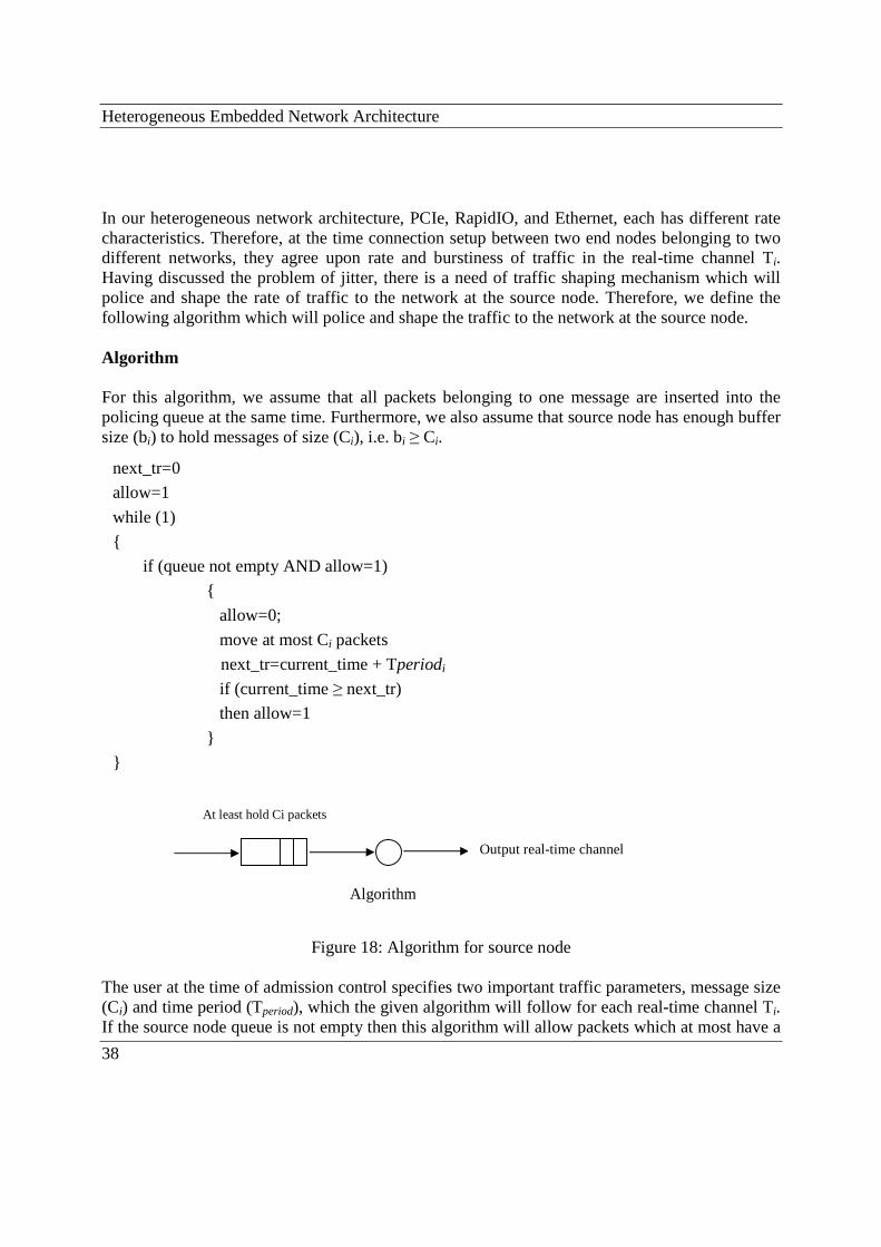
Heterogeneous Embedded Network Architecture
38
In our heterogeneous network architecture, PCIe, RapidIO, and Ethernet, each has different rate characteristics. Therefore, at the time connection setup between two end nodes belonging to two different networks, they agree upon rate and burstiness of traffic in the real-time channel Ti. Having discussed the problem of jitter, there is a need of traffic shaping mechanism which will police and shape the rate of traffic to the network at the source node. Therefore, we define the following algorithm which will police and shape the traffic to the network at the source node. Algorithm For this algorithm, we assume that all packets belonging to one message are inserted into the policing queue at the same time. Furthermore, we also assume that source node has enough buffer size (bi) to hold messages of size (Ci), i.e. bi ≥ Ci.
Figure 18: Algorithm for source node
The user at the time of admission control specifies two important traffic parameters, message size (Ci) and time period (Tperiod), which the given algorithm will follow for each real-time channel Ti. If the source node queue is not empty then this algorithm will allow packets which at most have a
next_tr=0
allow=1
while (1)
{
if (queue not empty AND allow=1)
{
allow=0;
move at most Ci packets
next_tr=current_time + Tperiodi
if (current_time ≥ next_tr)
then allow=1
}
}
At least hold Ci packets
Algorithm
Output real-time channel

Flow control
39
rate equal to Ci/Tperiod, which is periodic and is equal to rate of the traffic specified at the time of connection setup (admission control) between two nodes. This algorithm will restrict the user from transmitting packets more than the allowable message length Ci in a given time period (Tperiod) and will restrict the flow of the messages according to their respective bounded time period (Tperiod). After defining the operation of the proposed algorithm and traffic parameters, we can now implement it at the source node. Implementing algorithm at the source node Let us consider a real-time channel Ti originating from source node k. For each real-time channel we apply the proposed algorithm with a buffer size (bi) to hold messages of size (Ci), i.e. bi ≥ Ci. Then for each real-time channel Ti, originating from the source_nodek, the rate of periodic transmission will be:
Tperiodi
Ci
It means that the algorithm will enforce each real-time channel Ti to transmit at most Ci packets on a periodic basis i.e., Tperiod.
8.2 Flow Control at the gateway node At the gateway node as mentioned earlier we will consider Stop-and-Go queuing [18] [20] discipline for scheduling incoming packets on each incoming real-time channel to the output real-time channel. Stop-and-Go queuing discipline uses time periods (Tperiod) of constant length when serving packets. It considers a constant delay θ when serving packets, where 0 ≤ θ < Tperiod. This θ shows the difference between the packet arrival time at the gateway node and its local delay bound at the gateway node. Thus according to Stop-and-Go queuing discipline a packet which is arrived on a given real-time connection earlier than its given local delay bound are not eligible for transmission and will only receive service before its local Tperiod expires. Stop-and-Go ensures packets bound packets onto their respective local delay at the gateway node. If we say that the source characterises the traffic according to Ci and Tperiod on a given real-time channel Ti then at the gateway node Stop-and-Go will ensure that the same traffic characteristics are kept as the source node and thus end-to-end delay bound can be guaranteed. In [23] the author used the term "Delayed FIFO” for Stop-and-Go queuing discipline which means that the FIFO rule is incorporated into Stop-and-Go queuing service discipline. So if we consider a real-time channel Ti to be served on the gateway node, then according to Stop-and-Go queuing discipline for each real-time channel we might have a double-queue structure in which during each time period (Tperiod) one FIFO queue is loaded in while at the same time the other

Heterogeneous Embedded Network Architecture
40
FIFO queue is served from. When the time period for a packet belonging to the serving FIFO queue finishes, then this queue will start loading packets while the other queue will serving on output real-time channel. So this mechanism will keep the packets in loading FIFO queue until its local delay bound is guaranteed. For example: In the following figure we assume Stop-and-Go queuing discipline which is implemented for each real-time channel Ti at the gateway node. Each real-time channel Ti has some irregular arrival traffic patterns and we want to characterise the traffic pattern according to Ci / Tperiod on the gateway node.
Figure 19: Double queue structure of Stop-and-Go queuing strategy According to Stop-and-Go queuing discipline, we can see in figure 19 that it has double-queue structure with the names A and B. During a given time period (Tperiod), the FIFO queue A will load the packets and will delay the packet by value θ until its local delay bound expires. On the other hand during that Tperiod time the FIFO queue B will serve the eligible packet for transmission keeping its local delay bounded. When the FIFO queue B finish serving packet in a given Tperiod then on the next Tperiod the service control switch to start serving FIFO queue A while FIFO queue B will now load and buffer the packets. Thus in this way packets are loaded into the FIFO queue, delayed, and will serve only just before its local Tperiod expires. This service discipline ensures that packets will not miss their respective local deadline. We can replace the same double-queue structure of Stop-and-Go queuing discipline by single FIFO queue, as can be seen in figure20.
Figure 20: Single queue structure of Stop-and-Go queuing strategy
Server Arriving packets
B
A
Input Channel Ti
FIFO
FIFO Output channel
Server FIFO Queue
Service Controller
Arriving packets

Flow control
41
In single FIFO the service controller at the beginning of each time period marks the eligible packets in the queue using the deadline parameter of the packets and then connects the transmission facility to the queue just for the time needed to serve the eligible packets. After that, the service controller interrupts the service controller and waits for the next time period. In this way those non-eligible packets which are received during the current time period are not transmitted and will wait for their respective local delay bound. Though Stop-and-Go queuing discipline causes θi packets delay at the gateway node, its advantage is that it regulates the packets flow and keeping bound on packet’s deadline, thus avoiding from jitter and congestion problem. We can conclude this chapter by saying that for our heterogeneous embedded network, if we implement our proposed algorithm at the source node while using the Stop-and-Go queuing algorithm at the gateway node for each real-time channel that is been traversing end-to-end then we can avoid congestion problems and can have a guaranteed and deterministic service for respective real-time channel that has highest priority.

Heterogeneous Embedded Network Architecture
42
9 Conclusion The goal of the thesis was to carry out a case study when communication across gateway nodes takes place in a heterogeneous embedded networks system, seeking guaranteed performance. We studied the use of gateway nodes for emerging embedded switched network standards namely PCI Express, RapidIO, and well known standard Ethernet. We did a case study for six different gateway nodes operations when communication takes place in a heterogeneous embedded network. Different gateway nodes operations for communication in heterogeneous embedded network include fragmentation, addressing, and traffic class translation. Apart from the previously mentioned gateway nodes operations we also studied flow control mechanism at the source node as well as at the gateway node to avoid buffer overflow which is not affordable in high performance real-time embedded systems. For flow control at the source node we proposed an algorithm which regulates the packets whereas for the gateway node we used Stop-and-Go queuing service discipline. We also analysed end-to-end delay bound and maximum buffer size for a given communication real-time channel between any two nodes in heterogeneous embedded network systems.

References
43
10 References [1] Magnus Jonsson and Kristina Kunert, “Reliable Hard Real-Time Communication in Industrial
and Embedded Systems”, International Symposium on Industrial Embedded Systems, pp: 184 – 191, IEEE, 11-13 June 2008,
[2] Ajay V. Bhatt, “Creating a Third Generation I/O Interconnect”, Technology and Research
Labs, Intel Corporation, Desktop Architecture Labs Intel Corporation. [3] http://www.rapidio.org/education/technology_overview Visited on 14th June, 2008 [4] PCI Express Base Specification, Rev 1.1 [5] Sam Fuller, “RapidIO: The Embedded System Interconnect”, John Wiley, 2005, ISBN 0-470-09291-2, pp. 205-208. [6]http://www.cisco.com/en/US/docs/internetworking/technology/handbook/Ethernet.html.
visited on 21st September, 2008. [7] A. Rosdahl, F. Stigmarker “Switched Networks in Embedded Real-Time Systems”, master
thesis Chalmers University, EMW/FK-03:234 Rev.A, 2003 [8] David Mayhew and Venkata Krishnan, “PCI Express and Advanced Switching:
Evolutionary Path to Building Next Generation Interconnects”, Proceedings of the 11th Symposium on High Performance Interconnects, IEEE 2003.
[9] Greg Shippen, System Architect, “System Interconnect Fabrics: Ethernet versus RapidIO
Technology”, white paper, Document Number: AN3088, Rev. 0, 02/2007. [10] Vinton G. Cerf, Robert E. Kahn, "A Protocol for Packet Network Intercommunication”,
IEEE Transactions on Communications, Vol. 22, No. 5, May 1974, pp. 637-648. [11] Srinidhi Varadarajan, Tzi-cker Chiueh, “EtheReal: A Host-Transparent Real-Time Fast
Ethernet Switch ”, in Proceeding of International Conference on Network Protocols (ICNP), October 1998, pp.12-21.
[12] Hoang, H., M. Jonsson, U. Hagström, and A.kallerdahl, “Switched real-time Ethernet with
earliest deadline first scheduling – protocols and traffic handling,” Proc. Workshop on Prarallel and Distributed Real-time Systems (WPDRTS’2002) in conjunction with
Heterogeneous Embedded Network Architecture
44
International Parallel and Distributed Processing Symposium (IPDPS’02), Fort Lauderdale, FL, USA, April 15-16, 2002.
[13] B. Chen, A. Sahoo, W. Zhao, and A. Raha, “Connection-oriented communications for real-
time applications in FDDI-ATM-FDDI heterogeneous networks,” Proc. 17th International Conference on Distributed Computing Systems, pp. 225-234, 27-30 May 1997.
[14] L. M. Sanders, J. B. Evans, and B. J. Ewy, “Configuration Protocol for Embedded
Networked Devices on Secure Wireless Networks”, Conference paper, HPEC 2003. [15] M. Veeraraghavan., R. J. Munoz, and D. M. Rouse, “Interworking of addressing schemes in
an internetwork”, Global Telecommunications Conference, 2000. GLOBECOM '00. IEEE, Vol. 1, 27 Nov.-1 Dec. 2000, pp: 587-592.
[16] H. Zhang, “Service disciplines for guaranteed performance in packet-switched networks,”
proceedings of IEEE, vol. 83, no. 10, pp.1374-1396, Oct.1995. [17] Fan, X., M. Jonsson, and J. Jonsson, “Guaranteed real-time communication in packet-
switched networks with FCFS queuing,” Computer Networks, vol. 53, no. 3, pp. 400-417, Feb. 2009.
[18] S. Golestani, “Congestion-free transmission of real-time traffic in packet networks,” in Proc.
IEEE INFOCOM ’90, San Francisco, CA, June 1990, pp 527-542. [19] J. Turner, “New directions in communications, or Which way to the information age?,” lEEE
Commun. Mug., vol. 24, pp. 8-15, 1986. [20] S. J. Golestani, “ A Stop-and-Go queuing framework for congestion management,” in Proc.
ACM SIGCOMM ’90, Philadelphia, USA, Sept. 1990, pp. 8-18.