Embed Size (px)
Citation preview
IEEE TRANSACTIONS ON INDUSTRY APPLICATIONS, VOL. 51, NO. 5, SEPTEMBER/OCTOBER 2015 3829
Hexagon Voltage Manipulating Control (HVMC)for AC Motor Drives Operating at Voltage Limit
Jul-Ki Seok, Senior Member, IEEE, and SeHwan Kim, Student Member, IEEE
Abstract—This paper proposes a hexagon voltage manipulatingcontrol (HVMC) method for ac motor drives operating at voltagelimit. The command output voltage can be determined simplyby the torque command and the hexagon voltage boundary inthe absence of motor current-regulating proportional-integral (PI)control gains, additional flux weakening (FW) controllers, andobservers for closed-loop control. These attributes reduce the timeand effort needed for calibration of the controller in the nonlinearvoltage-limited region. The proposed HVMC accomplishes the“true” maximum available voltage utilization, allowing for higherefficiency than that of the current vector controller (CVC) alonein the FW domain. In addition, a voltage selection rule wasproposed to determine the unique HVMC solution between twopossible voltage vectors. The successful application of the controlapproach was corroborated by a graphical and analytical analysis.The proposed control approach is potentially applicable to a widerange of control designs for ac drives.
Index Terms—AC motor drives operating at voltage limit,hexagon voltage manipulating control (HVMC), maximum avail-able voltage utilization.
I. INTRODUCTION
THE growing penetration of ac motor drives into com-mercial, industrial, and transportation applications has
prompted the entry of current technology into voltageconstrained regions. Good examples of this trend include ultra-high-speed (> 120 000 r/min), high efficiency, and high-power-density drives, such as electrically assisted turbo chargers [1],[2], turbo compressors [3], [4], white goods applications [5],[6], and reduced dc-link capacitor technology for heating-ventilating-air-conditioning (HVAC) systems [7]–[9]. In theseemerging applications, rapid load torque changes and stricttorque regulation are not normally considered because partic-ular emphasis of system operation and design is placed onreliable high speed/high efficient operation and high-power-density drive control.
Manuscript received November 6, 2014; revised February 10, 2015; acceptedMarch 13, 2015. Date of publication March 23, 2015; date of current ver-sion September 16, 2015. Paper 2014-IDC-0802.R1, presented at the 2014IEEE Energy Conversion Congress and Exposition, Pittsburgh, PA, USA,September 20–24, and approved for publication in the IEEE TRANSACTIONSON INDUSTRY APPLICATIONS by the Industrial Drives Committee of the IEEEIndustry Applications Society. This work was supported by the 2014 YeungnamUniversity Research Grant.
The authors are with the School of Electrical Engineering, YeungnamUniversity, Gyeongbuk 712-749, Korea (e-mail: [email protected]; [email protected]).
Color versions of one or more of the figures in this paper are available onlineat http://ieeexplore.ieee.org.
Digital Object Identifier 10.1109/TIA.2015.2416125
The proportional-integral (PI) type current vector control(CVC) is the most widely used approach for achieving decou-pling control of an air-gap torque and flux linkage of ac motors[10]. PI-type CVC has a well-developed reach in technologyand has been a market success because of its robustness andsimplicity. Although it is excellent in the maximum-torque-per-ampere (MTPA) operation, the performance requirementsare satisfied with the help of multiple-objective sub-controlactions at voltage limit, such as the maximum-torque-per-voltage (MTPV) or flux weakening (FW) control, anti-windupcontrol, and over-modulation scheme. As a result, one majordifficulty under the voltage-limited region arises from the factthat sub-control actions conflict in subtle ways [11]. In addition,there are certain current limitations or load angle constraintsthat must be considered when designing a MTPV trackingcontroller. Therefore, the CVC strategy becomes more com-plicated under voltage-limited conditions because it requiresan extra control function and a tuning gains, which should beselected carefully based on the complex tradeoff between thedrive system stability and the control dynamics. Furthermore,realization of the maximum voltage utilization fails because thevoltage limit needs to be considered as a circle instead of ahexagon. Consequently, this control methodology increases thecopper loss and requires multiple control laws for the transitionbetween flux weakening and maximum voltage utilization.
As an alternative, some modified direct torque and flux con-trol (DTFC) schemes have been exploited for high performanceac motor drives [13], [14]. Despite their improved robustnessand transient performance over classical hysteretic direct torquecontrol algorithms, closed loop performance degradation stillremains when the controller operates at the constrained region.These adverse consequences arise from the adherence to thecontrol structure using the PI-type torque and flux regulator atthe nonlinear hexagonal voltage limit. One of the main reasonsfor using a PI regulator is the nonlinear cross-coupling ofthe voltage manipulated input, yielding both an air-gap torqueand stator flux linkage, which is not solvable directly andcannot be decoupled in continuous time. These have a closed-loop feedback structure to regulate the motor air-gap torqueand stator flux linkage. Therefore, the control performance isinfluenced directly by a stator flux linkage and torque observerdesign based on the motor model.
Recently, a finite-settling-step DTFC (FSS-DTFC) methodassociated with the inverter voltage and current constraints forinterior permanent-magnet synchronous motors (IPMSMs) wasproposed [11], [12]. The FSS-DTFC suggests that the inter-section of the current limited ellipse and the rotating hexagon
0093-9994 © 2015 IEEE. Personal use is permitted, but republication/redistribution requires IEEE permission.See http://www.ieee.org/publications_standards/publications/rights/index.html for more information.
3830 IEEE TRANSACTIONS ON INDUSTRY APPLICATIONS, VOL. 51, NO. 5, SEPTEMBER/OCTOBER 2015
becomes a feasible voltage vector at the next sampling instant.A closed-loop Volt-sec solution can correctly decouple thenonlinear cross-coupling of the applied voltage in the discretetime without adopting a PI-type regulator. The control lawdynamically scales the voltage vectors on the hexagonal voltageboundary to ensure the maximum torque capabilities undera given operating condition, while simultaneously regulatingthe stator flux linkage magnitude to meet the flux weakeningrequirements. The automatic transition to the FW mode wasachieved with a single voltage selection rule. In addition tothe stator flux linkage and torque observer, a closed-loop statorcurrent observer is essential for accurately tracking and esti-mating the change in current in each switching period. Thecomplicated design of multiple observers and the need to solvethe complex equation may prohibit its implementation on realindustrial drive systems.
This paper focuses on developing a hexagon voltage manip-ulating control (HVMC) method for ac motor drives operatingat various voltage limits. The command voltage vector at eachdiscrete time step can be determined simply by the torquecommand and the hexagon voltage boundary without requiringmotor current-regulating PI gains, additional FW controllers,and observers for a closed-loop torque and flux control. Theseattributes reduce the time and effort needed to calibrate thecontroller in the nonlinear voltage-limited region. The proposedHVMC accomplishes the “true” maximum available voltageutilization, allowing a higher efficiency than that of the CVCalone in the FW domain. Model-based voltage control (MVC)or CVC is performed under the MTPA region and motor controlis handed automatically over to the proposed HVMC in thevoltage shortage region. The automatic transition from theMTPA to FW mode provides new opportunities in a smalldc-link capacitor inverter fed by diode-bridge rectifiers, whichexperiences frequent dc-bus voltage shortages. The successfulapplication of the control approach has been corroborated bygraphical and analytical analysis. The proposed structure canoffer further flexibility in motor design and ac drive controloperating at various voltage limits.
II. HVMC DESIGN FOR AC MOTORS UNDER FW REGION
In this paper, an ac motor is considered to be salient when theq-axis inductance is larger than the d-axis inductance, whereasnon-salient if the d-axis inductance is identical to the q-axisinductance.
A. Non-Salient PM Motors
At the steady-state, the stator voltage equation of non-salientpermanent magnet (PM) motors can be expressed as
vds =Rsids − ωrLsiqs (1a)
vqs =Rsiqs + ωrLsids + ωrλpm (1b)
where vdqs and idqs are the stator voltage and current vectorin the synchronous coordinate, respectively. Rs is the statorresistance, ωr is the rotor angular velocity, λpm is the flux
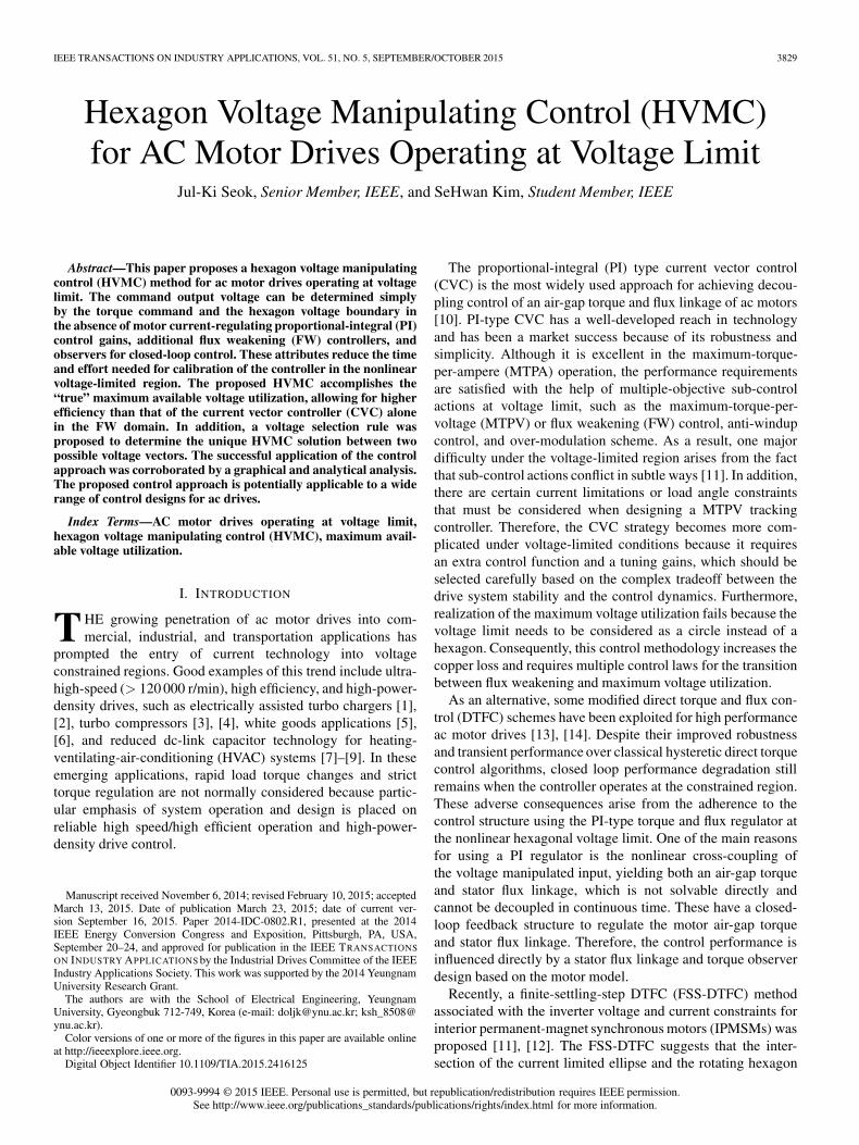
Fig. 1. Voltage selection principle for the HVMC operation of non-salient PMmotors.
linkage of the PM, and Ls denotes the stator inductance. Theq-axis stator current can be obtained as
iqs = −(
ωrLs
R2s + ω2
rL2s
)vds +
(Rs
R2s + ω2
rL2s
)vqs
− ωrRsλpm
R2s + ω2
rL2s
. (2)
The motor torque command can be described as a functionof the rotor speed and the d-q axis voltage as follows:
T∗e =
3
2
P
2λpmiqs
=3
2
P
2λpm
⎡⎣ −
(ωrLs
R2s+ω2
rL2s
)vds
+(
Rs
R2s+ω2
rL2s
)vqs − ωrRsλpm
R2s+ω2
r L2s
⎤⎦ (3)
where P denotes the number of poles.Fig. 1 provides a graphical representation of the stator volt-
age solutions between the torque command lines and rotatinghexagon in the synchronously rotating d-q voltage plane. Theboundary of each rotating hexagon sector can be modeled as astraight line in the d-q voltage plane [11], [12]
vqs(k) = Mn vds(k) + Bn (4)
where Mn and Bn are constant values given by the boundary ofeach hexagon sector.
The corresponding hexagon boundary and the torque com-mand of (3) can provide two possible stator voltage solutionsthat produce the desired output torque, as shown in Fig. 1.
Here, the command voltage vector, v∗dqs, is chosen as a
suitable solution at every sampling time
v∗ds=−T∗e
32
P2 λpm
+ωrRsλpm
R2s+ω2
rL2s−Bn
Rs
R2s+ω2
rL2s
ωrLs
R2s+ω2
rL2s−Mn
Rs
R2s+ω2
rL2s
(5a)
v∗qs=−Mn
⎛⎝ T∗
e32
P2 λpm
+ωrRsλpm
R2s+ω2
rL2s− Bn
Rs
R2s+ω2
r L2s
ωrLs
R2s+ω2
rL2s−Mn
Rs
R2s+ω2
r L2s
⎞⎠+Bn. (5b)
SEOK AND KIM: HVMC FOR AC MOTOR DRIVES OPERATING AT VOLTAGE LIMIT 3831
In the proposed HVMC method, the intersection of the torqueline and the rotating hexagon becomes the command voltagevector at the next sampling instant.
B. Salient PM Motors
The stator voltage equation of the salient ac motors can beexpressed as
vds = Rsids − ωrLqiqs (6a)vqs = Rsiqs + ωrLdids + ωrλpm (6b)
where Ldq indicates the d-q axis stator inductance. From (6),the d-q axis stator current can be obtained as
ids =
(Rs
R2s + ω2
rLdLq
)vds +
(ωrLq
R2s + ω2
rLdLq
)vqs
− ω2rLqλpm
R2s + ω2
rLdLq(7a)
iqs = −(
ωrLd
R2s + ω2
rLdLq
)vds +
(Rs
R2s + ω2
rLdLq
)vqs
− ωrRsλpm
R2s + ω2
rLdLq. (7b)
The motor torque command can be described as a functionof the rotor speed and the d-q axis voltage as follows:
T∗e
32P2
= λpm(kq1vds + kq2vqs + kq3)
+ (Ld−Lq)(kd1vds+kd2vqs+kd3)(kq1vds+kq2vqs+kq3)(8)
where
kd1 =Rs
R2s + ω2
rLdLq, kd2 =
ωrLq
R2s + ω2
rLdLq
kd3 = − ω2rLqλpm
R2s + ω2
rLdLq, kq1 = − ωrLd
R2s + ω2
rLdLq
kq2 =Rs
R2s + ω2
rLdLq, and kq3 = − ωrRsλpm
R2s + ω2
rLdLq.
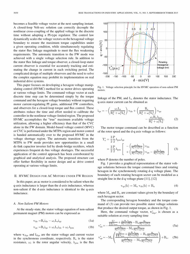
Fig. 2 shows the stator voltage solutions in the d-q voltageplane, where a torque command trajectory forms a hyperboliccurve. A suitable voltage vector at the corresponding intersec-tion between (4) and (8) can be obtained as follows:
v∗ds =−β −
√β2 − 4αγ
2αv∗qs = Mnv
∗ds +Bn (9)
where
α =(Ld−Lq){kd1kq1+kd2kq2M
2n+(kd1kq2+kd2kq1)Mn
}β = (Ld − Lq) {2kd2kq2MnBn + (kd1kq2 + kd2kq1)Bn
+kd1kq3 + kd3kq1 + (kd2kq3 + kd3kq2)Mn}+ λpmkq1 + λpmkq2Mn
γ = (Ld − Lq)(kd2kq2B2n + (kd2kq3 + kd3kq2) Bn + kd3kq3)
+ λpmkq2Bn + λpmkq3 −T∗
e32P2
.
Fig. 2. Voltage selection principle for the HVMC operation of salient PMmotors.
In (9), a single voltage solution, which falls on the hexagonalvoltage boundary, can be chosen as a feasible solution becauseonly one solution can be achieved at the next sampling time.
C. Induction Motors
At the steady-state, the motor air-gap torque and the rotorflux linkage of the rotor-flux oriented-controlled (RFO) IM canbe expressed as
Te =3
2
P
2
Lm
Lrλdriqs (10a)
λdr∼= Lmids (10b)
where λdr is the d-axis rotor flux linkage. Lm and Lr are themagnetizing and rotor inductance, respectively.
The stator voltage equation can also be simplified as
vds = Rsids − ωeσLsiqs (11a)
vqs = Rsiqs + ωeLsids (11b)
where σLs is the stator transient leakage inductance.By combining (10) and (11), the rotor flux linkage and torque
command can be obtained as a function of the synchronousspeed
λ∗dr = Lm
Rs
R2s + ω2
eσL2s
vds + LmωeσLs
R2s + ω2
eσL2s
vqs (12)
T∗e =
3
2
P
2
Lm
Lrλ∗dr
(− ωeLs
R2s+ω2
eLsσLsvds
+ Rs
R2s+ω2
eLsσLsvqs
). (13)
The motor torque command can be obtained as follow:
T∗e =
3
2
P
2
Lm
Lr(kd1_IMvds + kd2_IMvqs)
× (kq1_IMvds + kq2_IMvqs) (14)
3832 IEEE TRANSACTIONS ON INDUSTRY APPLICATIONS, VOL. 51, NO. 5, SEPTEMBER/OCTOBER 2015
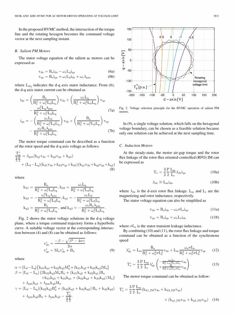
Fig. 3. Voltage selection principle for the HVMC operation of inductionmotors.
where
kd1_IM = LmRs
R2s + ω2
eσL2s
kd2_IM = LmωeσLs
R2s + ω2
eσL2s
, kq1_IM = − ωeLs
R2s + ω2
eσL2s
, and
kq2_IM =Rs
R2s + ω2
eσL2s
.
Fig. 3 shows the stator voltage solutions in the d-q voltage plane.A feasible voltage vector can be obtained as follows:
v∗ds =−β ±
√β2 − 4αγ
2αv∗qs = Mnv
∗ds +Bn (15)
where
α = kd1_IMkq1_IM + (kd1_IMkq2_IM + kd2_IMkq1_IM)Mn
+ kd2_IMkq2_IMM2n
β = (kd1_IMkq2_IM + kd2_IMkq1_IM)Bn
+ 2kd2_IMkq2_IMMnBn, and
γ = kd2_IMkq2_IMB2n −
T∗e
32P2Lm
Lr
.
D. Natural Flux-Weakening Operation
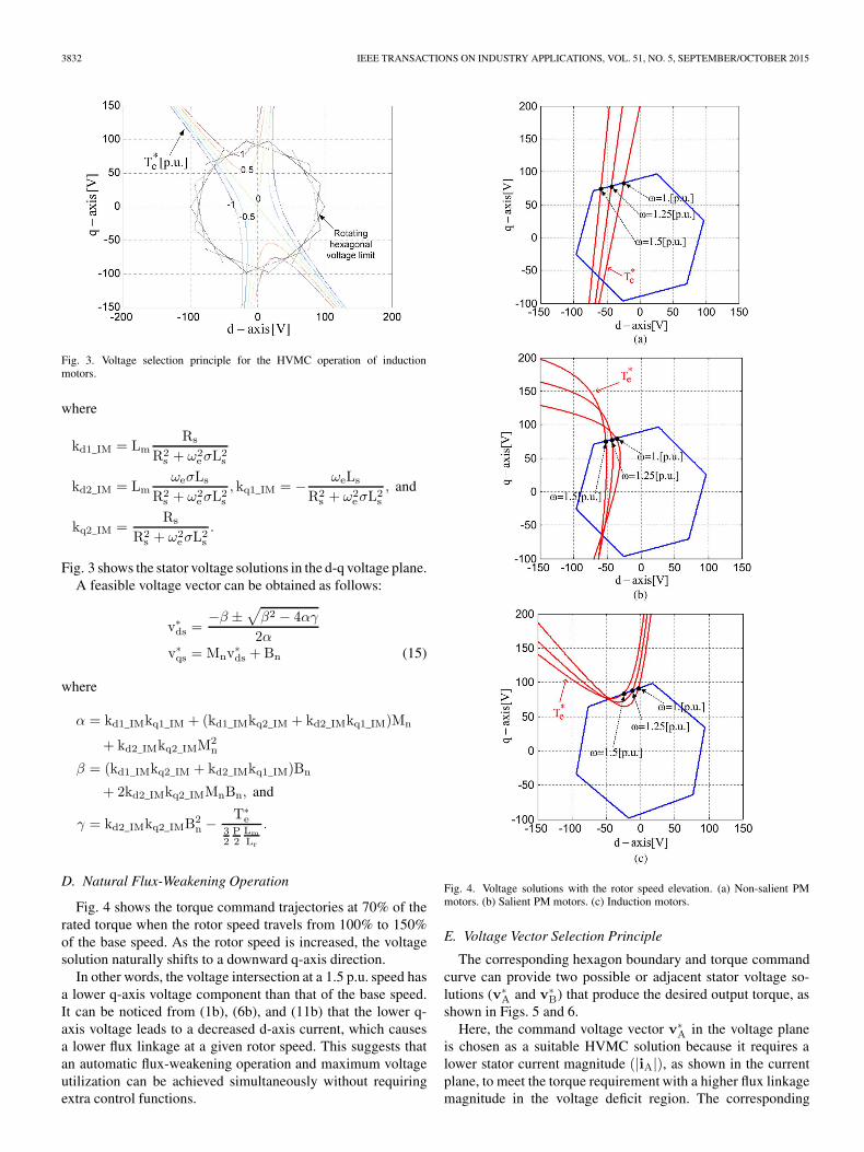
Fig. 4 shows the torque command trajectories at 70% of therated torque when the rotor speed travels from 100% to 150%of the base speed. As the rotor speed is increased, the voltagesolution naturally shifts to a downward q-axis direction.
In other words, the voltage intersection at a 1.5 p.u. speed hasa lower q-axis voltage component than that of the base speed.It can be noticed from (1b), (6b), and (11b) that the lower q-axis voltage leads to a decreased d-axis current, which causesa lower flux linkage at a given rotor speed. This suggests thatan automatic flux-weakening operation and maximum voltageutilization can be achieved simultaneously without requiringextra control functions.
Fig. 4. Voltage solutions with the rotor speed elevation. (a) Non-salient PMmotors. (b) Salient PM motors. (c) Induction motors.
E. Voltage Vector Selection Principle
The corresponding hexagon boundary and torque commandcurve can provide two possible or adjacent stator voltage so-lutions (v∗
A and v∗B) that produce the desired output torque, as
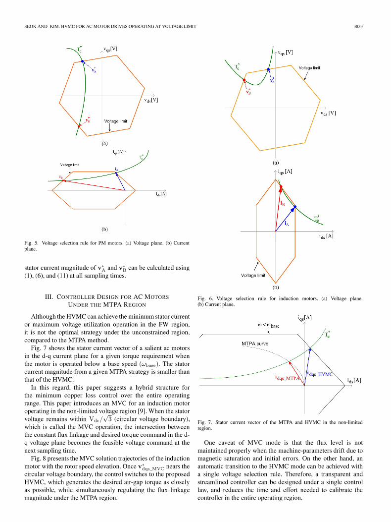
shown in Figs. 5 and 6.Here, the command voltage vector v∗
A in the voltage planeis chosen as a suitable HVMC solution because it requires alower stator current magnitude (|iA|), as shown in the currentplane, to meet the torque requirement with a higher flux linkagemagnitude in the voltage deficit region. The corresponding
SEOK AND KIM: HVMC FOR AC MOTOR DRIVES OPERATING AT VOLTAGE LIMIT 3833
Fig. 5. Voltage selection rule for PM motors. (a) Voltage plane. (b) Currentplane.
stator current magnitude of v∗A and v∗
B can be calculated using(1), (6), and (11) at all sampling times.
III. CONTROLLER DESIGN FOR AC MOTORS
UNDER THE MTPA REGION
Although the HVMC can achieve the minimum stator currentor maximum voltage utilization operation in the FW region,it is not the optimal strategy under the unconstrained region,compared to the MTPA method.
Fig. 7 shows the stator current vector of a salient ac motorsin the d-q current plane for a given torque requirement whenthe motor is operated below a base speed (ωbase). The statorcurrent magnitude from a given MTPA strategy is smaller thanthat of the HVMC.
In this regard, this paper suggests a hybrid structure forthe minimum copper loss control over the entire operatingrange. This paper introduces an MVC for an induction motoroperating in the non-limited voltage region [9]. When the statorvoltage remains within Vdc/
√3 (circular voltage boundary),
which is called the MVC operation, the intersection betweenthe constant flux linkage and desired torque command in the d-q voltage plane becomes the feasible voltage command at thenext sampling time.
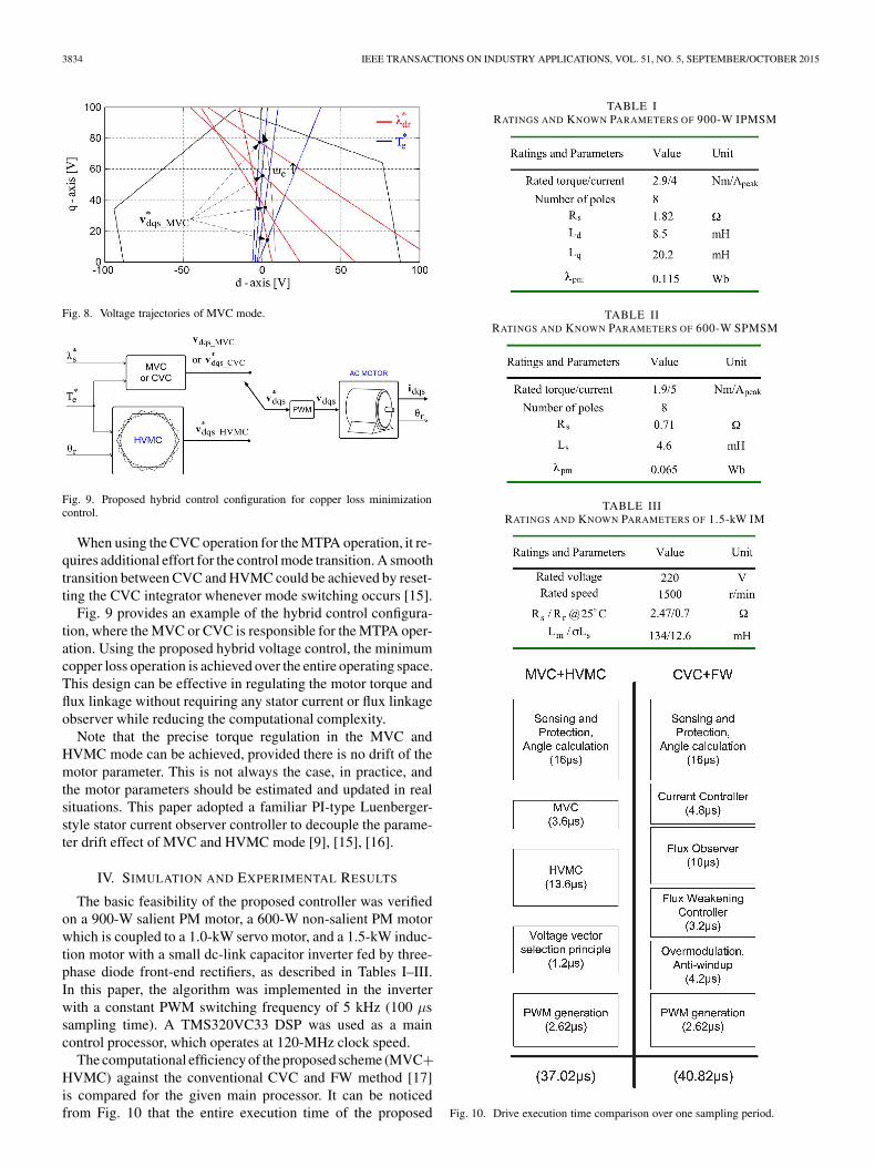
Fig. 8 presents the MVC solution trajectories of the inductionmotor with the rotor speed elevation. Once v∗
dqs_MVC nears thecircular voltage boundary, the control switches to the proposedHVMC, which generates the desired air-gap torque as closelyas possible, while simultaneously regulating the flux linkagemagnitude under the MTPA region.
Fig. 6. Voltage selection rule for induction motors. (a) Voltage plane.(b) Current plane.
Fig. 7. Stator current vector of the MTPA and HVMC in the non-limitedregion.
One caveat of MVC mode is that the flux level is notmaintained properly when the machine-parameters drift due tomagnetic saturation and initial errors. On the other hand, anautomatic transition to the HVMC mode can be achieved witha single voltage selection rule. Therefore, a transparent andstreamlined controller can be designed under a single controllaw, and reduces the time and effort needed to calibrate thecontroller in the entire operating region.
3834 IEEE TRANSACTIONS ON INDUSTRY APPLICATIONS, VOL. 51, NO. 5, SEPTEMBER/OCTOBER 2015
Fig. 8. Voltage trajectories of MVC mode.
Fig. 9. Proposed hybrid control configuration for copper loss minimizationcontrol.
When using the CVC operation for the MTPA operation, it re-quires additional effort for the control mode transition. A smoothtransition between CVC and HVMC could be achieved by reset-ting the CVC integrator whenever mode switching occurs [15].
Fig. 9 provides an example of the hybrid control configura-tion, where the MVC or CVC is responsible for the MTPA oper-ation. Using the proposed hybrid voltage control, the minimumcopper loss operation is achieved over the entire operating space.This design can be effective in regulating the motor torque andflux linkage without requiring any stator current or flux linkageobserver while reducing the computational complexity.
Note that the precise torque regulation in the MVC andHVMC mode can be achieved, provided there is no drift of themotor parameter. This is not always the case, in practice, andthe motor parameters should be estimated and updated in realsituations. This paper adopted a familiar PI-type Luenberger-style stator current observer controller to decouple the parame-ter drift effect of MVC and HVMC mode [9], [15], [16].
IV. SIMULATION AND EXPERIMENTAL RESULTS
The basic feasibility of the proposed controller was verifiedon a 900-W salient PM motor, a 600-W non-salient PM motorwhich is coupled to a 1.0-kW servo motor, and a 1.5-kW induc-tion motor with a small dc-link capacitor inverter fed by three-phase diode front-end rectifiers, as described in Tables I–III.In this paper, the algorithm was implemented in the inverterwith a constant PWM switching frequency of 5 kHz (100 μssampling time). A TMS320VC33 DSP was used as a maincontrol processor, which operates at 120-MHz clock speed.
The computational efficiency of the proposed scheme (MVC+HVMC) against the conventional CVC and FW method [17]is compared for the given main processor. It can be noticedfrom Fig. 10 that the entire execution time of the proposed
TABLE IRATINGS AND KNOWN PARAMETERS OF 900-W IPMSM
TABLE IIRATINGS AND KNOWN PARAMETERS OF 600-W SPMSM
TABLE IIIRATINGS AND KNOWN PARAMETERS OF 1.5-kW IM
Fig. 10. Drive execution time comparison over one sampling period.
SEOK AND KIM: HVMC FOR AC MOTOR DRIVES OPERATING AT VOLTAGE LIMIT 3835
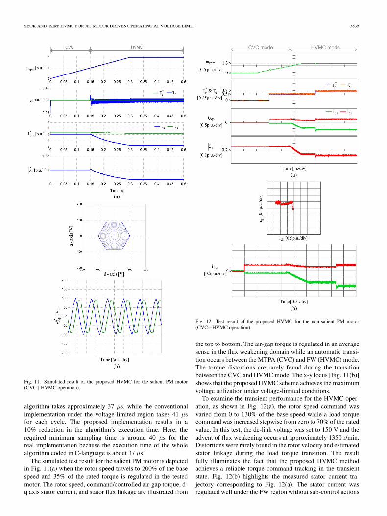
Fig. 11. Simulated result of the proposed HVMC for the salient PM motor(CVC+HVMC operation).
algorithm takes approximately 37 μs, while the conventionalimplementation under the voltage-limited region takes 41 μsfor each cycle. The proposed implementation results in a10% reduction in the algorithm’s execution time. Here, therequired minimum sampling time is around 40 μs for thereal implementation because the execution time of the wholealgorithm coded in C-language is about 37 μs.
The simulated test result for the salient PM motor is depictedin Fig. 11(a) when the rotor speed travels to 200% of the basespeed and 35% of the rated torque is regulated in the testedmotor. The rotor speed, command/controlled air-gap torque, d-q axis stator current, and stator flux linkage are illustrated from
Fig. 12. Test result of the proposed HVMC for the non-salient PM motor(CVC+HVMC operation).
the top to bottom. The air-gap torque is regulated in an averagesense in the flux weakening domain while an automatic transi-tion occurs between the MTPA (CVC) and FW (HVMC) mode.The torque distortions are rarely found during the transitionbetween the CVC and HVMC mode. The x-y locus [Fig. 11(b)]shows that the proposed HVMC scheme achieves the maximumvoltage utilization under voltage-limited conditions.
To examine the transient performance for the HVMC oper-ation, as shown in Fig. 12(a), the rotor speed command wasvaried from 0 to 130% of the base speed while a load torquecommand was increased stepwise from zero to 70% of the ratedvalue. In this test, the dc-link voltage was set to 150 V and theadvent of flux weakening occurs at approximately 1350 r/min.Distortions were rarely found in the rotor velocity and estimatedstator linkage during the load torque transition. The resultfully illuminates the fact that the proposed HVMC methodachieves a reliable torque command tracking in the transientstate. Fig. 12(b) highlights the measured stator current tra-jectory corresponding to Fig. 12(a). The stator current wasregulated well under the FW region without sub-control actions
3836 IEEE TRANSACTIONS ON INDUSTRY APPLICATIONS, VOL. 51, NO. 5, SEPTEMBER/OCTOBER 2015
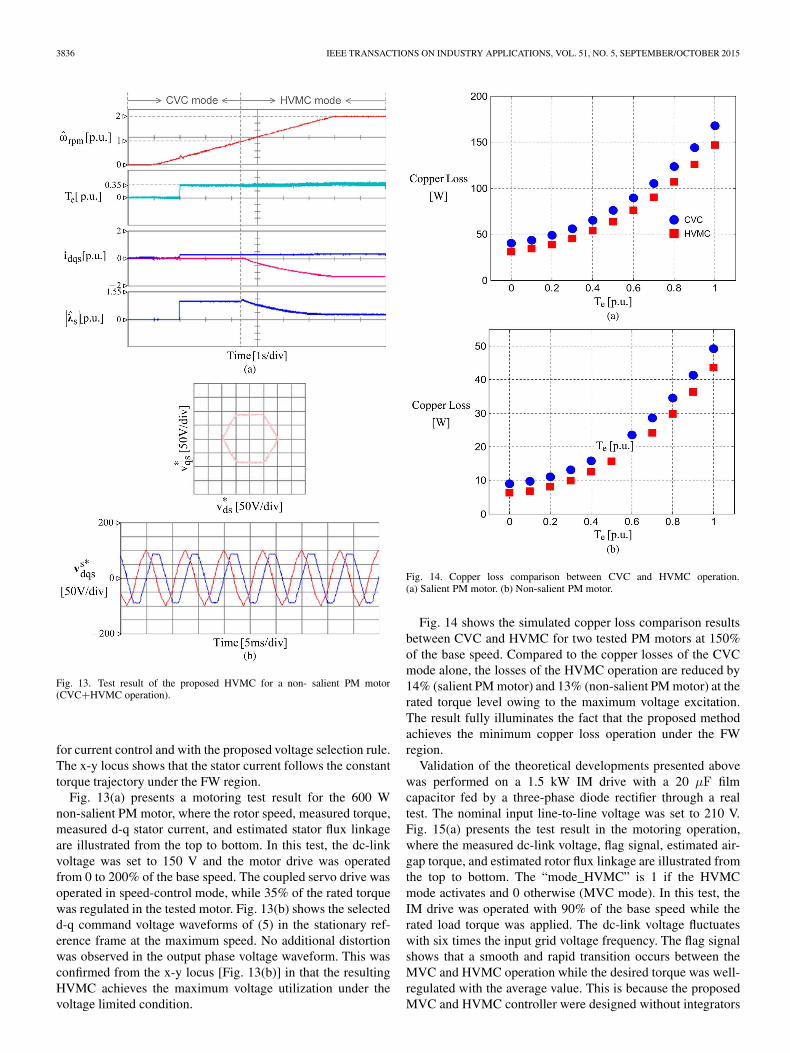
Fig. 13. Test result of the proposed HVMC for a non- salient PM motor(CVC+HVMC operation).
for current control and with the proposed voltage selection rule.The x-y locus shows that the stator current follows the constanttorque trajectory under the FW region.
Fig. 13(a) presents a motoring test result for the 600 Wnon-salient PM motor, where the rotor speed, measured torque,measured d-q stator current, and estimated stator flux linkageare illustrated from the top to bottom. In this test, the dc-linkvoltage was set to 150 V and the motor drive was operatedfrom 0 to 200% of the base speed. The coupled servo drive wasoperated in speed-control mode, while 35% of the rated torquewas regulated in the tested motor. Fig. 13(b) shows the selectedd-q command voltage waveforms of (5) in the stationary ref-erence frame at the maximum speed. No additional distortionwas observed in the output phase voltage waveform. This wasconfirmed from the x-y locus [Fig. 13(b)] in that the resultingHVMC achieves the maximum voltage utilization under thevoltage limited condition.
Fig. 14. Copper loss comparison between CVC and HVMC operation.(a) Salient PM motor. (b) Non-salient PM motor.
Fig. 14 shows the simulated copper loss comparison resultsbetween CVC and HVMC for two tested PM motors at 150%of the base speed. Compared to the copper losses of the CVCmode alone, the losses of the HVMC operation are reduced by14% (salient PM motor) and 13% (non-salient PM motor) at therated torque level owing to the maximum voltage excitation.The result fully illuminates the fact that the proposed methodachieves the minimum copper loss operation under the FWregion.
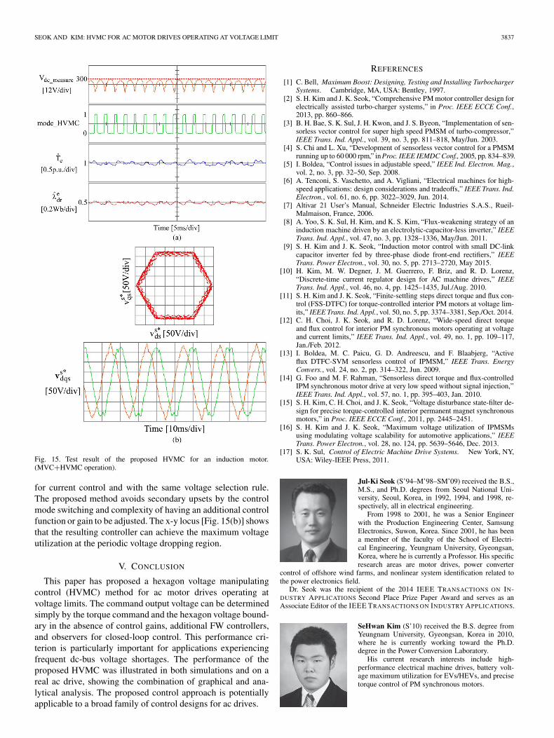
Validation of the theoretical developments presented abovewas performed on a 1.5 kW IM drive with a 20 μF filmcapacitor fed by a three-phase diode rectifier through a realtest. The nominal input line-to-line voltage was set to 210 V.Fig. 15(a) presents the test result in the motoring operation,where the measured dc-link voltage, flag signal, estimated air-gap torque, and estimated rotor flux linkage are illustrated fromthe top to bottom. The “mode_HVMC” is 1 if the HVMCmode activates and 0 otherwise (MVC mode). In this test, theIM drive was operated with 90% of the base speed while therated load torque was applied. The dc-link voltage fluctuateswith six times the input grid voltage frequency. The flag signalshows that a smooth and rapid transition occurs between theMVC and HVMC operation while the desired torque was well-regulated with the average value. This is because the proposedMVC and HVMC controller were designed without integrators
SEOK AND KIM: HVMC FOR AC MOTOR DRIVES OPERATING AT VOLTAGE LIMIT 3837
Fig. 15. Test result of the proposed HVMC for an induction motor.(MVC+HVMC operation).
for current control and with the same voltage selection rule.The proposed method avoids secondary upsets by the controlmode switching and complexity of having an additional controlfunction or gain to be adjusted. The x-y locus [Fig. 15(b)] showsthat the resulting controller can achieve the maximum voltageutilization at the periodic voltage dropping region.
V. CONCLUSION
This paper has proposed a hexagon voltage manipulatingcontrol (HVMC) method for ac motor drives operating atvoltage limits. The command output voltage can be determinedsimply by the torque command and the hexagon voltage bound-ary in the absence of control gains, additional FW controllers,and observers for closed-loop control. This performance cri-terion is particularly important for applications experiencingfrequent dc-bus voltage shortages. The performance of theproposed HVMC was illustrated in both simulations and on areal ac drive, showing the combination of graphical and ana-lytical analysis. The proposed control approach is potentiallyapplicable to a broad family of control designs for ac drives.
REFERENCES
[1] C. Bell, Maximum Boost: Designing, Testing and Installing TurbochargerSystems. Cambridge, MA, USA: Bentley, 1997.
[2] S. H. Kim and J. K. Seok, “Comprehensive PM motor controller design forelectrically assisted turbo-charger systems,” in Proc. IEEE ECCE Conf.,2013, pp. 860–866.
[3] B. H. Bae, S. K. Sul, J. H. Kwon, and J. S. Byeon, “Implementation of sen-sorless vector control for super high speed PMSM of turbo-compressor,”IEEE Trans. Ind. Appl., vol. 39, no. 3, pp. 811–818, May/Jun. 2003.
[4] S. Chi and L. Xu, “Development of sensorless vector control for a PMSMrunning up to 60 000 rpm,” inProc. IEEE IEMDC Conf., 2005, pp. 834–839.
[5] I. Boldea, “Control issues in adjustable speed,” IEEE Ind. Electron. Mag.,vol. 2, no. 3, pp. 32–50, Sep. 2008.
[6] A. Tenconi, S. Vaschetto, and A. Vigliani, “Electrical machines for high-speed applications: design considerations and tradeoffs,” IEEE Trans. Ind.Electron., vol. 61, no. 6, pp. 3022–3029, Jun. 2014.
[7] Altivar 21 User’s Manual, Schneider Electric Industries S.A.S., Rueil-Malmaison, France, 2006.
[8] A. Yoo, S. K. Sul, H. Kim, and K. S. Kim, “Flux-weakening strategy of aninduction machine driven by an electrolytic-capacitor-less inverter,” IEEETrans. Ind. Appl., vol. 47, no. 3, pp. 1328–1336, May/Jun. 2011.
[9] S. H. Kim and J. K. Seok, “Induction motor control with small DC-linkcapacitor inverter fed by three-phase diode front-end rectifiers,” IEEETrans. Power Electron., vol. 30, no. 5, pp. 2713–2720, May 2015.
[10] H. Kim, M. W. Degner, J. M. Guerrero, F. Briz, and R. D. Lorenz,“Discrete-time current regulator design for AC machine drives,” IEEETrans. Ind. Appl., vol. 46, no. 4, pp. 1425–1435, Jul./Aug. 2010.
[11] S. H. Kim and J. K. Seok, “Finite-settling steps direct torque and flux con-trol (FSS-DTFC) for torque-controlled interior PM motors at voltage lim-its,” IEEE Trans. Ind. Appl., vol. 50, no. 5, pp. 3374–3381, Sep./Oct. 2014.
[12] C. H. Choi, J. K. Seok, and R. D. Lorenz, “Wide-speed direct torqueand flux control for interior PM synchronous motors operating at voltageand current limits,” IEEE Trans. Ind. Appl., vol. 49, no. 1, pp. 109–117,Jan./Feb. 2012.
[13] I. Boldea, M. C. Paicu, G. D. Andreescu, and F. Blaabjerg, “Activeflux DTFC-SVM sensorless control of IPMSM,” IEEE Trans. EnergyConvers., vol. 24, no. 2, pp. 314–322, Jun. 2009.
[14] G. Foo and M. F. Rahman, “Sensorless direct torque and flux-controlledIPM synchronous motor drive at very low speed without signal injection,”IEEE Trans. Ind. Appl., vol. 57, no. 1, pp. 395–403, Jan. 2010.
[15] S. H. Kim, C. H. Choi, and J. K. Seok, “Voltage disturbance state-filter de-sign for precise torque-controlled interior permanent magnet synchronousmotors,” in Proc. IEEE ECCE Conf., 2011, pp. 2445–2451.
[16] S. H. Kim and J. K. Seok, “Maximum voltage utilization of IPMSMsusing modulating voltage scalability for automotive applications,” IEEETrans. Power Electron., vol. 28, no. 124, pp. 5639–5646, Dec. 2013.
[17] S. K. Sul, Control of Electric Machine Drive Systems. New York, NY,USA: Wiley-IEEE Press, 2011.
Jul-Ki Seok (S’94–M’98–SM’09) received the B.S.,M.S., and Ph.D. degrees from Seoul National Uni-versity, Seoul, Korea, in 1992, 1994, and 1998, re-spectively, all in electrical engineering.
From 1998 to 2001, he was a Senior Engineerwith the Production Engineering Center, SamsungElectronics, Suwon, Korea. Since 2001, he has beena member of the faculty of the School of Electri-cal Engineering, Yeungnam University, Gyeongsan,Korea, where he is currently a Professor. His specificresearch areas are motor drives, power converter
control of offshore wind farms, and nonlinear system identification related tothe power electronics field.
Dr. Seok was the recipient of the 2014 IEEE TRANSACTIONS ON IN-DUSTRY APPLICATIONS Second Place Prize Paper Award and serves as anAssociate Editor of the IEEE TRANSACTIONS ON INDUSTRY APPLICATIONS.
SeHwan Kim (S’10) received the B.S. degree fromYeungnam University, Gyeongsan, Korea in 2010,where he is currently working toward the Ph.D.degree in the Power Conversion Laboratory.
His current research interests include high-performance electrical machine drives, battery volt-age maximum utilization for EVs/HEVs, and precisetorque control of PM synchronous motors.