Embed Size (px)
Citation preview

XIEGU
X5105HF/50MHZ Portable Short-wave Transceiver
Operation Manual
V3.0 Preview Edition
Content
1
2
3
6
Basic characteristicsPanel keysLeft interfaceRight interface 7
8
9
10
12
Handheld microphone functionDescription for external interfaces Charging and maintenance of build-in batteryConnection of external power suppliesMenu operation 14
15
17
34
35
36
37
38
39
40
41
42
43
44
45
47
Panel keysMulti-function menuTransceiver start and shutdownBattery level/voltage indicationSelection of working frequency rangeSelection of working mode (MODE)Volume adjustmentAdjustment of transmitting power (Po)Use of PTT key of the deviceWorking frequency settingsAutomatic antenna tuner (ATU)Fine tuning of received frequency (RIT)Automatic gain control (AGC)Pre-amplification/front attenuation (ATT)SPL and VFO settingsVFO/MEMO mode switch 48
49
50
51
52
Key lock/backlight off LockCW communicationPreset message editing and sendingChannel managerData communication by connecting with computer 53
54
56
56
57
58
59
System parameter configurationComputer control instructionsWave band voltage dataIndicatorsAttached itemsSchematic diagram of connection between existing models of Xiegu and XPA125/125BSchematic diagram of CE-19 expansion card interface 60
Basic Characteristics
2
X5105 is a kind of ultra-portable short-wave full-mode transceiver that integrates all functions required by
short-wave amateur radio operations and realizes portable/mobile use of short-wave equipment in the real sense. Its
strong functions and performance make you easily deal with various states in communications and hear signals from
all over the world. HF+50MHz full-mode 5W output Small size (about 168*93*47mm), which is portable 3.6-cun large dot matrix LCD Built-in large capacity lithium battery pack (3800mAh @ 12V) Built-in efficient automatic antenna tuner Built-in digital baseband, which can achieve many advanced functions:
Digital noise reduction, digital NOTCH Digital EQ equalizer Variable bandwidth digital filter Direct-decoding amateur radio common data mode Capable of directly finishing data communication based on an external adapter without PC or separate modem CW, PSK, RTTY automatic decoding/preset message transmitting
Built-in high-stability TCXO Manual/auto telegram key mode switch Wide working voltage rangePlease read this manual carefully for a better experience and full understanding on operation of the X5105.
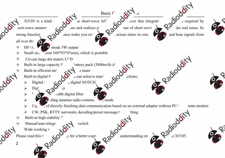
Panel Keys
3
11
2223
X5105T/R DATA LINK
LOCK
PREATT MODE
MENU
V/M
A/B
NB RIT
ATU Po
<
1
2
3
45
6
7 8 9 10
12
13
14
15
16
17
18
192021 ABC
Panel Keys
4
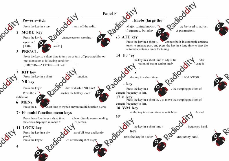
1 Power switchPress the key in a long time to turn on or turn off the radio.
2 MODE key Press the key in a short time to change current working mode and cycle in following sequence: [ LSB-USB-CW-CWR-NFM-AM ]
3 PRE/ATT keyPress the key in a short time to turn on or turn off pre-amplifier or pre-attenuator as following conditions: [ PRE=ON---ATT=ON---PRE/ATT=OFF ]
4 RIT key Press the key in a short time to enable RIT function.
5 NB keyPress the key in a short time to enable or disable NB function.
Press the key in a long time to switch the battery level/voltage indication.
6 MENU key Press the key in a short time to switch current multi-function menu.
7~10 multi-function menu keysPress these four keys a short time to enable or disable corresponding functions displayed in menu area on current screen.
11 LOCK keyPress the key in a short time to lock actions of all keys and knobs on panel; Press the key for 1s to turn on or turn off backlight of display screen.
12 Major knobs (large thumbwheel)Major tuning knobs of radio can not only be used to adjust frequency, but also can be used to set parameters.
13 ATU keyPress the key in a short time to connect built-in automatic antenna tuner to antenna port, and press the key in a long time to start the automatic antenna tuner for tuning.
14 Po key Press the key in a short time to adjust transmitting power under the cooperation of major tuning knob. The adjustment range is 0.1W~5W.
15 A/B keyPress the key in a short time to switch between VFOA/VFOB.
16 < keyPress the key in a short time to move the stepping position of
current frequency to left. 17 > key
Press the key in a short time to move the stepping position of current frequency to left. 18 V/M key
Press the key in a short time to switch between VFO mode and MEMO mode.
Press the key in a short time to switch to a higher frequency band. 20 DN key
Press the key in a short time to a lower frequency band.
19 UP key
Panel Keys
5
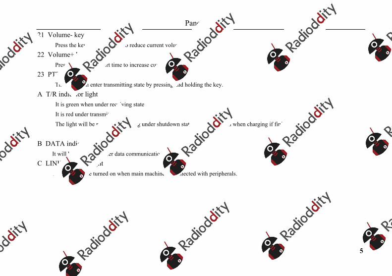
21 Volume- keyPress the key in a short time to reduce current volume.
22 Volume+ keyPress the key in a short time to increase current volume.
23 PTT key The radio will enter transmitting state by pressing and holding the key.
A T/R indicator light It is green when under receiving state
It is red under transmitting state
The light will be red when charging under shutdown state. It will be green when charging if finished.
B DATA indicator light It will be flickering under data communication state.
C LINK indicator light The light will be turned on when main machine is connected with peripherals.

Left Interface
6
24 Antenna interface BNC type interface with impedance being 500.
25 Medium frequency signal outlet
Output and receive first medium frequency signals. 26 Left bracketStretch it outward when using it. Fold side backplate when it is not used.
27 Earphone interface
It is a 3.5mm stereo socket (3 wires) interface used to connect earphone devices. * It shall be noted that functions of the interface will be different as
for different version of X5105.
28 DC power interface It is an external DC power input interface used to connect
external DC power by using attached power lines. External
DC power supply shall be capable of supplying power
output of 13.8V@3A. The interface can be also used to
charge build-in battery.
+-EXT DC
24
25
26
27
28
Right Interface
7
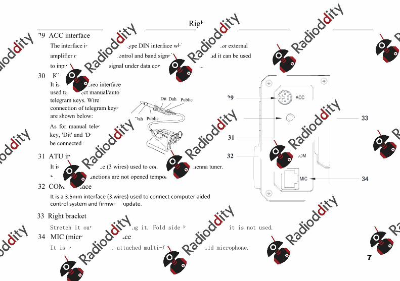
29 ACC interface The interface is an 8-core mini-type DIN interface which can be used for external
amplifier connection, PTT control and band signal transmission, and it can be used
to input/output acoustic signal under data communication state.
30 KEY interfaceIt is a 3.5mm stereo interface used to connect manual/auto telegram keys. Wire connection of telegram keys are shown below:
As for manual telegram key, 'Dit' and 'Dah' shall be connected together.
31 ATU interface It is a 3.5mm interface (3 wires) used to control external antenna tuner.
*The interface functions are not opened temporarily.
32 COM interface It is a 3.5mm interface (3 wires) used to connect computer aided control system and firmware update.
33 Right bracketStretch it outward when using it. Fold side backplate when it is not used.
34 MIC (microphone) interface
It is used to connect attached multi-function handheld microphone.
ACC
KEY
ATU
COM
MIC
29
30
31
33
32
34
Dit
Dit
Dah
Dah
Public
Public
Handheld Microphone Function
8
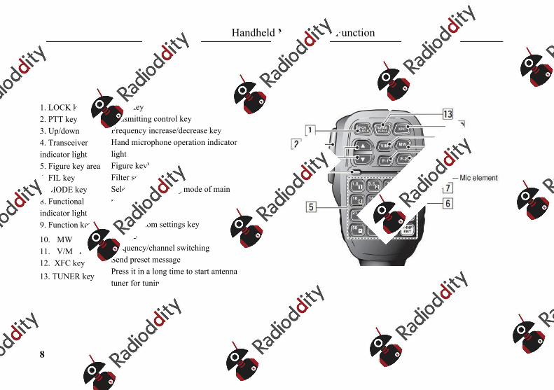
1. LOCK key2. PTT key3. Up/down4. Transceiver indicator light5. Figure key area6. FIL key7. MODE key8. Functional indicator light9. Function keys
10. MW key11. V/M key12. XFC key13. TUNER key
Lock keytransmitting control keyFrequency increase/decrease keyHand microphone operation indicator lightFigure keyboard areaFilter selectionSelection of working mode of main machine NoF1/F2 custom settings keyStorage Frequency/channel switchingSend preset messagePress it in a long time to start antenna tuner for tuning
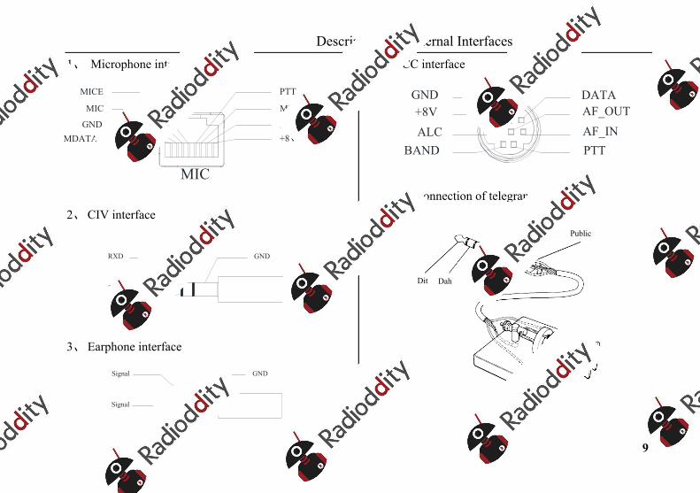
Description for External Interfaces
9
1、 Microphone interface
2、 CIV interface
3、 Earphone interface
4、 ACC interface
5、Wire connection of telegram keys
MIC
MDATAGND
MIC
MICE PTT
MSVSW
NC+8V
TXD
RXD GND
Signal
Signal GND
PTTBANDAF_INAF_OUT
ALC
DATA+8V
GND
Dit Dah Public
Dit Dah Public
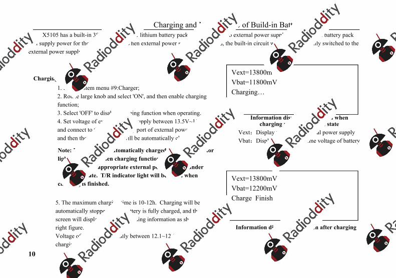
Charging and Maintenance of Build-in Battery
10
X5105 has a built-in 3800mAh polymer lithium battery pack. When there is no external power supply connected, the battery pack will supply power for the whole device. When external power supply is provided, the built-in circuit will be automatically switched to the external power supply.
5. The maximum charging time is 10-12h. Charging will beautomatically stopped when battery is fully charged, and the screen will display charging finishing information as shown in right figure. Voltage of battery is generally between 12.1~12.5V after charging.
Charging method: 1. Enter system menu #9:Charger;2. Rotate large knob and select 'ON', and then enable chargingfunction; 3. Select 'OFF' to disable charging function when operating.4. Set voltage of external power supply between 13.5V~15.0Vand connect to the power supply port of external power source, and then the main machine will be automatically charged.
Note: X5105 will be automatically charged and T/R indicator light will be red when charging function is enabled and connected with appropriate external power supply under shutdown state. T/R indicator light will be green when charging is finished.
Vext=13800mV Vbat=11800mV Charging…
Information displayed on screen when charging under shutdown state
Vext:Display voltage of external power supply Vbat:Display current real-time voltage of battery
Vext=13800mV Vbat=12200mV Charge Finish
Information displayed on screen after charging
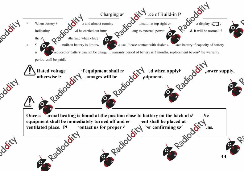
Charging and Maintenance of Build-in Battery
11
○ When battery is supplying power and almost running out, the power indicator at top right corner of screen will display ,
indicating that charging shall be carried out immediately or switching to external power supply is required. It will be normal if
the shell is slightly exothermic when charging.
○ Service life of the built-in battery is limited under normal use. Please contact with dealer to replace battery if capacity of battery
is obviously reduced or battery can not be charged (warranty period of battery is 3 months, replacement beyond the warranty
period shall be paid).
Rated voltage range of equipment shall not be exceeded when applying external power supply, otherwise irreversible damages will be caused to equipment.
Once abnormal heating is found at the position close to battery on the back of shell, the equipment shall be immediately turned off and equipment shall be placed at a safe and ventilated place. Please contact us for proper disposal after confirming safety conditions.
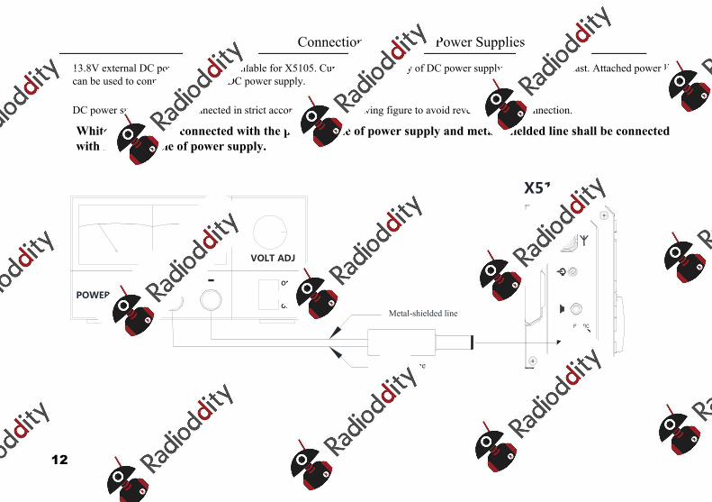
Connection of External Power Supplies
12
13.8V external DC power supply is available for X5105. Current load capacity of DC power supply shall be 3A at least. Attached power lines can be used to connect to radio and DC power supply.
DC power supply shall be connected in strict accordance with following figure to avoid reverse polarity connection.
White line shall be connected with the positive pole of power supply and metal-shielded line shall be connected with negative pole of power supply.
+-EXT DC
POWER SUPPLY
VOLT ADJ
+ -
White line
Metal-shielded line
ON
OFF
X5105
Connection of External Power Supplies
13
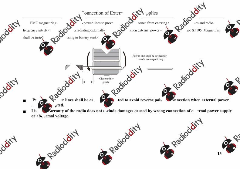
EMC magnet ring can be applied on power lines to prevent external disturbance from entering radio via power lines and radio-
frequency interference in radio from radiating externally via power lines when external power supply is adopted for X5105. Magnet ring
shall be installed at the side closing to battery socket.
Polarity of power lines shall be carefully inspected to avoid reverse polarity connection when external power supply is adopted.
Limited warranty of the radio does not include damages caused by wrong connection of external power supply or abnormal voltage.
Power line shall be twined for 2 rounds on magnet ring.
Close to interface to greatest extent
Operation
14
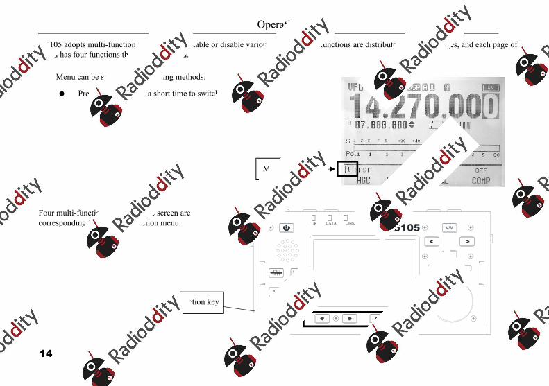
X5105 adopts multi-function menu mode to enable or disable various functions. All functions are distributed in 9 menu pages, and each page of menu has four functions that can be selected.
Menu can be switched in following methods:
Press MENU key in a short time to switch menu pages.
Four multi-function keys under the screen are corresponding to displayed function menu.
Menu page
X5105T/R DATA LINK
LOCK
PREATT MODE
MENU
V/M
A/B
NB RIT
ATU Po
<
Multi-function key
Operation
15
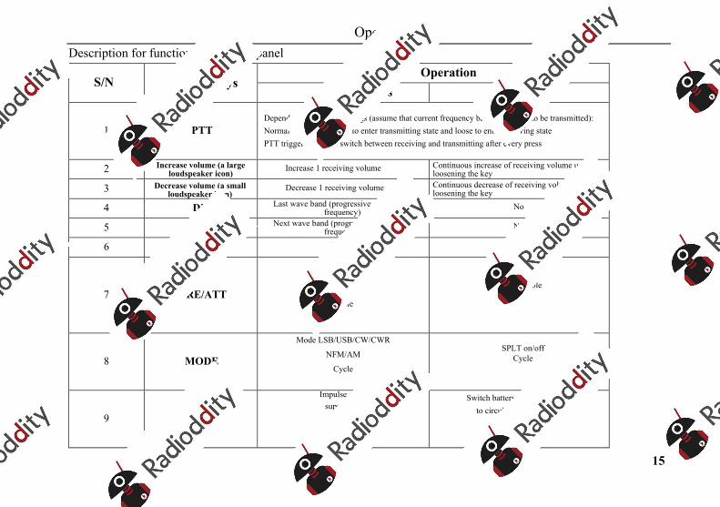
Description for functions of keys on panel
S/N Name of keysOperation
Short press Long press
1 PTT Depend on PTT mode settings (assume that current frequency band is allowed to be transmitted): Normal PTT mode: press to enter transmitting state and loose to enter receiving statePTT triggering mode: switch between receiving and transmitting after every press
2 Increase volume (a large loudspeaker icon) Increase 1 receiving volume Continuous increase of receiving volume until
loosening the key
3 Decrease volume (a small loudspeaker icon)
Decrease 1 receiving volume Continuous decrease of receiving volume until loosening the key
4 DN Last wave band (progressive decrease of frequency) No
5 UP Next wave band (progressive increase of frequency) No
6 PWR None Power ON/OFF
7 PRE/ATT
BypassPRE ONATT ON
Cycle
Not available
8 MODE
Mode LSB/USB/CW/CWR
NFM/AM
Cycle
SPLT on/offCycle
9 NB
Impulse noise suppressor
On/OffCycle
Switch battery gauge/voltmeter to circularly display them
Operation
16
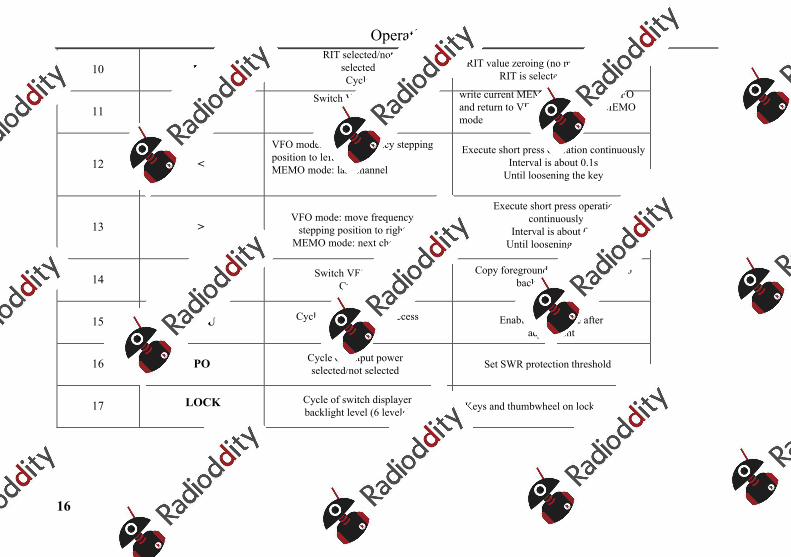
10 RIT RIT selected/not
selectedCycle
RIT value zeroing (no matter whether RIT is selected or not)
11 V/M Switch VFO/MEMO
modeCycle
write current MEMO parameters in VFO and return to VFO mode if under MEMO mode
12 <
VFO mode: move frequency stepping position to leftMEMO mode: last channel
Execute short press operation continuouslyInterval is about 0.1s
Until loosening the key
13 > VFO mode: move frequency
stepping position to rightMEMO mode: next channel
Execute short press operation continuously
Interval is about 0.1sUntil loosening the key
14 A/B Switch VFO A/BCycle
Copy foreground VFO parameters to background VFO
15 ATU Cycle of ATU bypass/access switch
Start ATUEnable access state after
adjustment
16 PO Cycle of output power selected/not selected Set SWR protection threshold
17 LOCK Cycle of switch displayer backlight level (6 levels) Keys and thumbwheel on lock panel
Operation
17
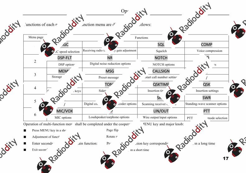
Functions of each page in multi-function menu are distributed as follows:
Menu page Functions
1 AGC RF-GAIN SQL COMP
AGC speed selection Receiving radio frequency gain adjustment Squelch Voice compression
2 DSP-FLT NR NOTCH EQ
DSP options Digital noise reduction options NOTCH options EQ options
3 MEMO MSG CALLSIGN /
Storage options Preset message Start call number settings /
4 KEY TONE QSKTIME QSK
Options of telegram keys Sidetone settings Insertion time settings Insertion settings
5 / DIGI SRM SWR
/ Digital communication decoder options Scanning receiver options Standing-wave scanner options
6 MIC/VOX S/P LIN/OUT PTT
MIC options Loudspeaker/earphone options Wire output/input options PTT triggering mode selection
Operation of multi-function menu shall be completed under the cooperation of MENU key and major knob:
Press MENU key in a short time: Page flip
Adjustment of functional parameters: Rotate major knob
Enter secondary menu of a certain function: Press the multi-function key corresponding to the function in a long time
Exit secondary menu Press MENU key in a short time
Operation
18
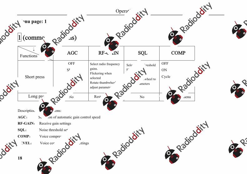
Menu page: 1
1 (common functions)
Key labelsFunctions AGC RF-GAIN SQL COMP
Short press
OFF
SLOW
FAST
AUTO
Cycle
Select radio frequency gains. Flickering when selectedRotate thumbwheel to adjust parameters
Select noise thresholdFlickering when selectedRotate thumbwheel to adjust parameters
OFF
ON
Cycle
Long press No Restore defaults No Enter 1-4 submenu
Description of key functions:
AGC: Selection of automatic gain control speed
RF-GAIN: Receive gain settings
SQL: Noise threshold settings
COMP: Voice compression settings
LEVEL: Voice compression ratio settings
Operation
19
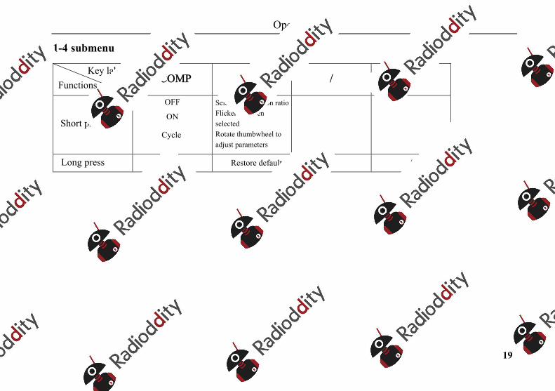
1-4 submenu
Key labelsFunctions COMP LEVEL / /
Short press
OFF
ON
Cycle
Select compression ratioFlickering when selectedRotate thumbwheel to adjust parameters
Long press No Restore defaults / /
Operation
20
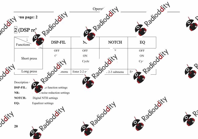
Menu page: 2
2 (DSP related)
Key labelsFunctions DSP-FIL NR NOTCH EQ
Short press
OFF
ON
Cycle
OFF
ON
Cycle
OFF
ON
Cycle
OFF
ON
Cycle
Long press Enter 2-1 submenu Enter 2-2 submenu Enter 2-3 submenu Enter 2-4 submenu
Description of key functions:
DSP-FIL: Digital filter function settings
NR: Digital noise reduction settings
NOTCH: Digital NTH settings
EQ: Equalizer settings
Operation
21
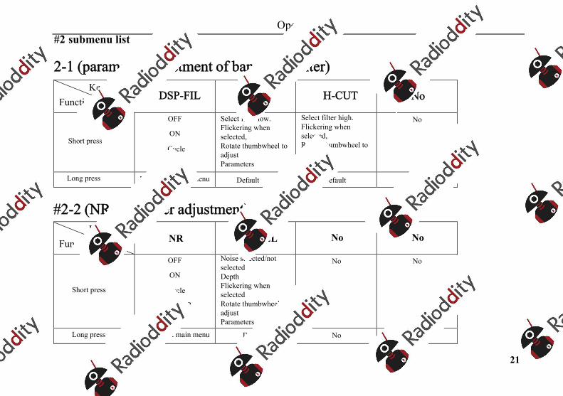
#2 submenu list
2-1 (parameter adjustment of band-pass filter)Key labels
Functions DSP-FIL L-CUT H-CUT No
Short press
OFF
ON
Cycle
Select filter low. Flickering when selected, Rotate thumbwheel to adjust Parameters
Select filter high. Flickering when selected, Rotate thumbwheel to adjust Parameters
No
Long press Return to 2 main menu Default Default No
#2-2 (NR parameter adjustment)Key labels
Functions NR LEVEL No No
Short press
OFF
ON
Cycle
Toggle NR
ON/OFF
Noise selected/not selectedDepthFlickering when selectedRotate thumbwheel to adjust Parameters
No No
Long press Return to 2 main menu Default No No

Operation
22
#2-3 (NOTCH parameter adjustment)
Key labelsFunctions NOTCH CNT BW No
Short press
OFF
ON
Cycle
Notch selected/not selectedFrequency pointFlickering when selectedRotate thumbwheel to adjust Parameters
Notch selected/not selectedBandwidthFlickering when selectedRotate thumbwheel to adjust Parameters
No
Long press Return to 2 main menu Default Default No
#2-4 (EQ parameter adjustment)
Key labelsFunctions BASS MEDI TREB EQ
Short press
Bass selected/not selectedFlickering when selectedRotate thumbwheel to adjust parameters
Alto voice selected/not selectedFlickering when selectedRotate thumbwheel to adjust parameters
High-pitched voice selected/not selectedFlickering when selectedRotate thumbwheel to adjust parameters
OFF
ON
Cycle
Long press Default Default Default Return to 2 main menu
Operation
23
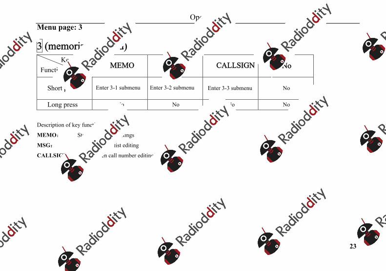
Menu page: 3
3 (memorizer related) Key labels
Functions MEMO MSG CALLSIGN No
Short press Enter 3-1 submenu Enter 3-2 submenu Enter 3-3 submenu No
Long press No No No No
Description of key functions:
MEMO: Storage channel settings
MSG: Preset message list editing
CALLSIGN: Boot screen call number editing
Operation
24
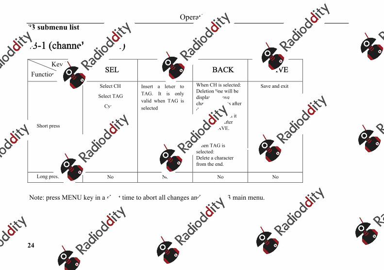
#3 submenu list
#3-1 (channel manager)
Key labelsFunctions SEL INS BACK SAVE
Short press
Select CH
Select TAG
Cycle
Insert a letter to TAG. It is only valid when TAG is selected
When CH is selected: Deletion line will be displayed above channel contents after deleting current channel, and then it will be valid after pressing SAVE.
When TAG is selected: Delete a character from the end.
Save and exit
Long press No No No No
Note: press MENU key in a short time to abort all changes and return to 3 main menu.
Operation
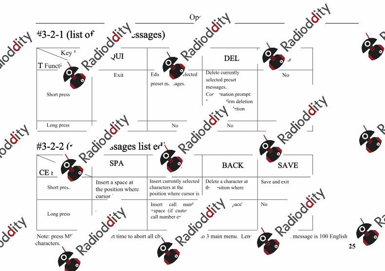
25
#3-2-1 (list of preset messages)
Key labels QUIT Functions
EDIT DEL No
Short press
Exit Edit currently selected
preset messages.
Delete currently selected preset messages. Confirmation prompt: YES: confirm deletionNO: abort deletion
No
Long press No No No No
#3-2-2 (preset messages list editor)Key labels SPA
CE FunctionsINS BACK SAVE
Short pressInsert a space at the position where cursor is
Insert currently selected characters at the position where cursor is
Delete a character at the position where cursor is
Save and exit
Long press Insert 'DE+space'Insert call number+space (if customized call number exists)
Insert 'CQ+space' No
Note: press MENU key in a short time to abort all changes and return to 3 main menu. Length of each preset message is 100 English characters.
Operation
26
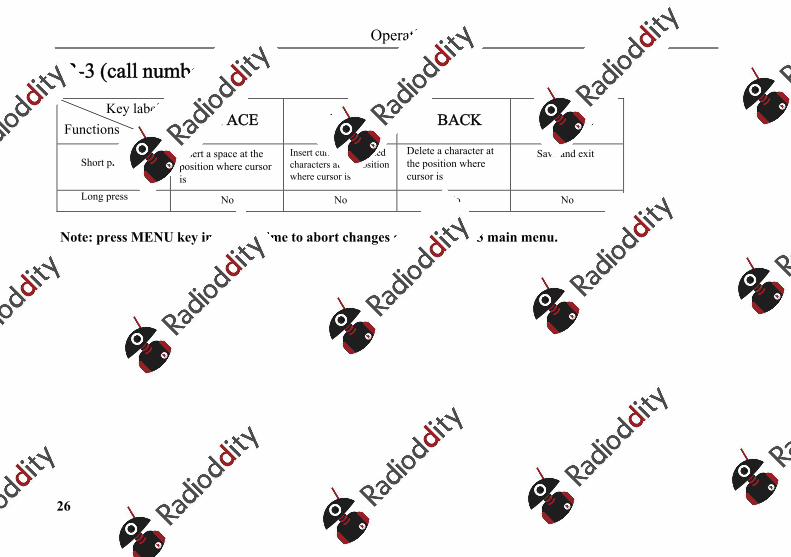
#3-3 (call number editor)
Key labels Functions SPACE INS BACK SAVE
Short pressInsert a space at the position where cursor is
Insert currently selected characters at the position where cursor is
Delete a character at the position where cursor is
Save and exit
Long press No No No No
Note: press MENU key in a short time to abort changes and return to 3 main menu.
Operation
27
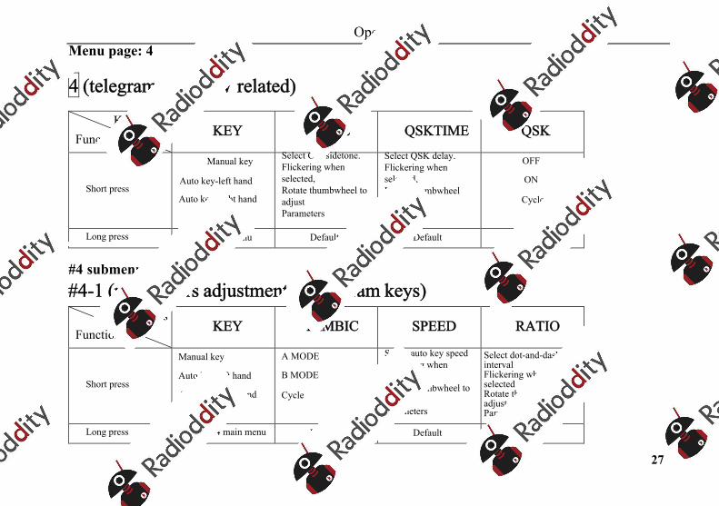
Menu page: 4
4 (telegram keys/CW related)
Key labels Functions KEY TONE QSKTIME QSK
Short press
Manual key
Auto key-left hand
Auto key-right hand
Cycle
Select CW sidetone. Flickering when selected, Rotate thumbwheel to adjust Parameters
Select QSK delay. Flickering when selected, Rotate thumbwheel to adjust Parameters
OFF
ON
Cycle
Long press Enter 4-1 submenu Default Default Default
#4 submenu list #4-1 (parameters adjustment of telegram keys)
Key labelsFunctions KEY IAMBIC SPEED RATIO
Short press
Manual key
Auto key-left hand
Auto key-right hand
Cycle
A MODE
B MODE
Cycle
Select auto key speedFlickering when selectedRotate thumbwheel to adjust Parameters
Select dot-and-dash intervalFlickering when selectedRotate thumbwheel to adjust Parameters
Long press Return to 4 main menu Default Default Default
Operation
28
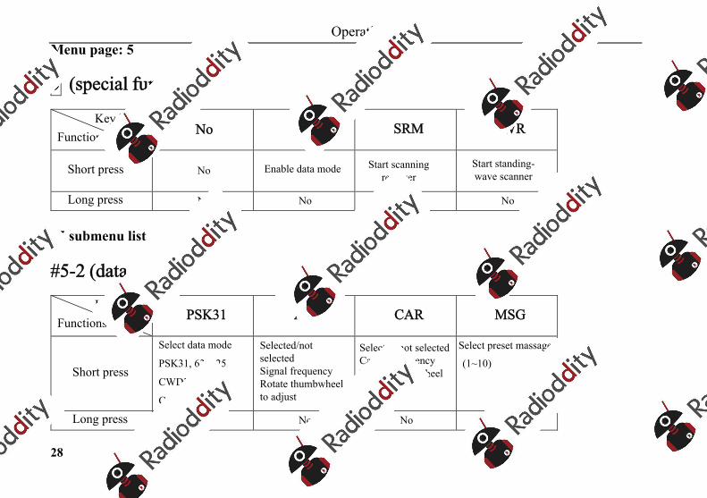
Menu page: 5
5 (special functions)
Key labels Functions No DIGI SRM SWR
Short press No Enable data mode Start scanning receiver
Start standing-wave scanner
Long press No No No No
#5 submenu list
#5-2 (data mode)
Key labels Functions PSK31 AFC CAR MSG
Short press
Select data mode
PSK31, 63, 125
CWDEM, RTTY
Cycle
Selected/not selectedSignal frequencyRotate thumbwheel to adjust
Selected/not selectedCarrier frequencyRotate thumbwheel to adjust
Select preset massages
(1~10)
Long press No No No No
Operation
29
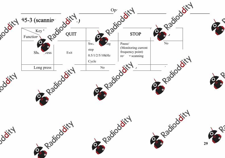
#5-3 (scanning receiver)
Key labels Functions QUIT BW STOP No
Short press Exit
Switch scanning
step
0.5/1/2/5/10kHz
Cycle
Pause/(Monitoring current frequency point) recover scanning Cycle
No
Long press No No No No
Operation
30
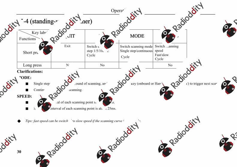
#5-4 (standing-wave scanner)
Key labels Functions QUIT BW MODE SPEED
Short pressExit Switch scanning
step 1/5/10kHzCycle
Switch scanning modeSingle step/continuous
Cycle
Switch scanning speedFast/slowCycle
Long press No No No No
Clarifications:MODE:
Single step: stop after every round of scanning, and then press PTT key (onboard or Hand microphone PTT) to trigger next scanning
Continuous: continuous scanning.
SPEED: Fast: time interval of each scanning point is about 12ms.
Slow: time interval of each scanning point is about 25ms.
Tips: fast speed can be switched to slow speed if the scanning curve is not stable.
Operation
31
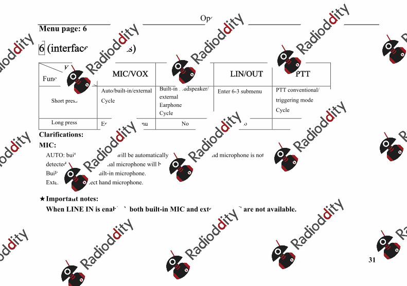
Menu page: 6
6 (interface functions)
Key labels Functions MIC/VOX SPK LIN/OUT PTT
Short press
Auto/built-in/external
Cycle
Built-in loudspeaker/externalEarphoneCycle
Enter 6-3 submenu PTT conventional/
triggering mode
Cycle
Long press Enter 6-1 submenu No No No
Clarifications:MIC:
AUTO: built-in microphone will be automatically selected when hand microphone is not detected, otherwise external microphone will be selected. Built-in INT: select built-in microphone. External EXT: select hand microphone.
★Important notes: When LINE IN is enabled, both built-in MIC and external MIC are not available.
Operation
32
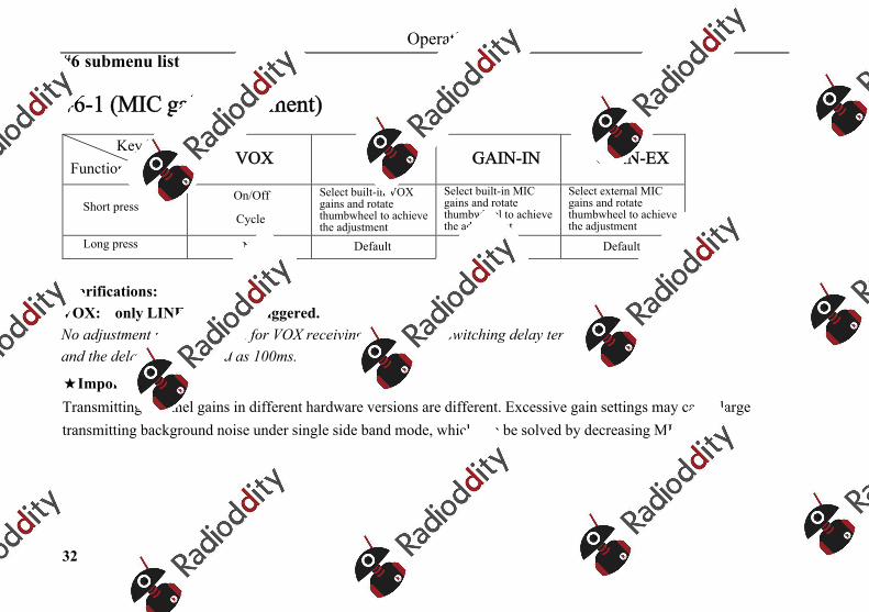
#6 submenu list
#6-1 (MIC gain adjustment)
Key labelsFunctions VOX G-VOX GAIN-IN GAIN-EX
Short pressOn/Off
Cycle
Select built-in VOX gains and rotate thumbwheel to achieve the adjustment
Select built-in MIC gains and rotate thumbwheel to achieve the adjustment
Select external MIC gains and rotate thumbwheel to achieve the adjustment
Long press No Default Default Default
Clarifications:VOX: only LINE IN can be triggered. No adjustment menu provided for VOX receiving and sending switching delay temporarily, and the delay is determined as 100ms.
★Important notes: Transmitting channel gains in different hardware versions are different. Excessive gain settings may cause large transmitting background noise under single side band mode, which can be solved by decreasing MIC GAIN.
Operation
33
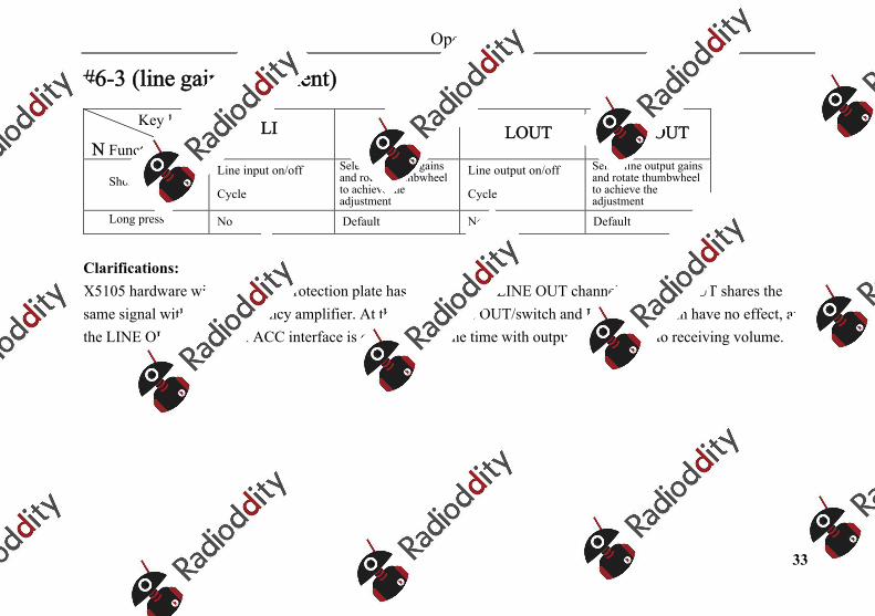
#6-3 (line gain adjustment)
Key labels LIN Functions
G-LIN LOUT G-LOUT
Short pressLine input on/off
Cycle
Select line input gains and rotate thumbwheel to achieve the adjustment
Line output on/off
Cycle
Select line output gains and rotate thumbwheel to achieve the adjustment
Long press No Default No Default
Clarifications:X5105 hardware without screen protection plate has no individual LINE OUT channel. Its LINE OUT shares the same signal with audio frequency amplifier. At this time, LINE OUT/switch and LINE OUT gain have no effect, and the LINE OUT terminal of ACC interface is outputting all the time with output level related to receiving volume.
Operation
34
Routine operation
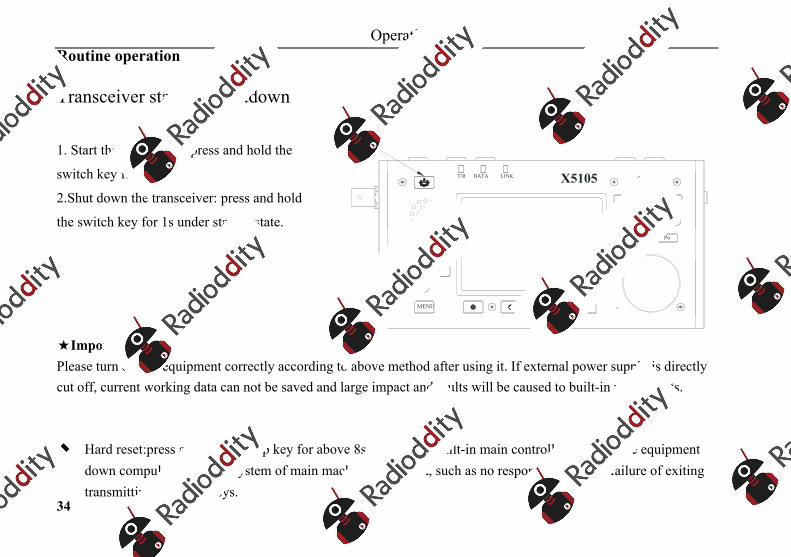
Transceiver start and shutdown
1. Start the transceiver: press and hold the
switch key for 1s.
2.Shut down the transceiver: press and hold
the switch key for 1s under startup state.
★Important notes: Please turn off the equipment correctly according to above method after using it. If external power supply is directly cut off, current working data can not be saved and large impact and faults will be caused to built-in power units.
Hard reset:press and hold startup key for above 8s to reset the built-in main controller and shut the equipment down compulsively when system of main machine is crashed, such as no response of keys or failure of exiting transmitting state and keys.
X5105T/R DATA LINK
LOCK
PREATT MODE
MENU
V/M
A/B
NB RIT
ATU Po
<
Switch key

Operation
35
Battery level/voltage indication
If the X5105 transceiver is not used for more than 30 days, we suggest to connect it with an external power supply to charge it until the charging is finished. See operation instructions in [Charging] for details.
Press NB key to switch the battery level/voltage indication.
Operation
36
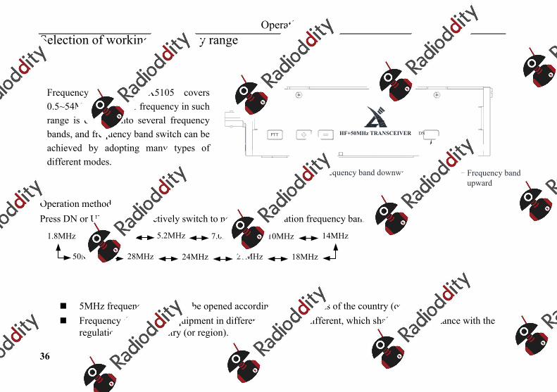
Selection of working frequency range
Operation methods:Press DN or UP key to respectively switch to next or last operation frequency band.
3.5MHz 7.0MHz 10MHz 14MHz
18MHz21MHz24MHz
1.8MHz
28MHz
5.2MHz
50MHz
5MHz frequency band shall be opened according to regulations of the country (or region). Frequency division for equipment in different versions is different, which shall be in accordance with the
regulations of the country (or region).
Frequency range of X5105 covers 0.5~54MHz. Amateur frequency in such range is divided into several frequency bands, and frequency band switch can be achieved by adopting many types of different modes.
PTT HF+50MHz TRANSCEIVER DN UP
Frequency band downward Frequency band upward
Operation
37
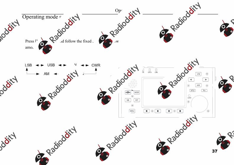
Operating mode selection
Press [MODE] key and follow the fixed sequence below among all modes
X5105T/R DATA LINK
LOCK
PREATT MODE
MENU
V/M
A/B
NB RIT
ATU Po
<
Mode
Operation
38
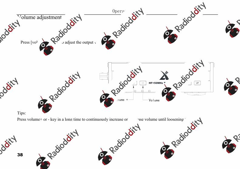
Volume adjustment
Tips: Press volume+ or - key in a long time to continuously increase or decrease volume until loosening the key.
PTT DN UPHF+50MHz TRANSCEIVER
Volume + Volume -
Press [volume+, -] key to adjust the output volume
Operation
39
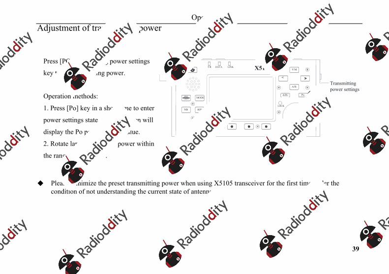
Adjustment of transmitting power
Please minimize the preset transmitting power when using X5105 transceiver for the first time under the condition of not understanding the current state of antenna.
Press [PO] transmitting power settings
key to set transmitting power.
Operation methods:
1. Press [Po] key in a short time to enter
power settings state, and the screen will
display the Po power setting value.
2. Rotate large knob to set power within
the range of 0.1W-5W.
X5105T/R DATA LINK
LOCK
PREATT MODE
MENU
V/M
A/B
NB RIT
ATU Po
<
Transmitting power settings
Operation
40
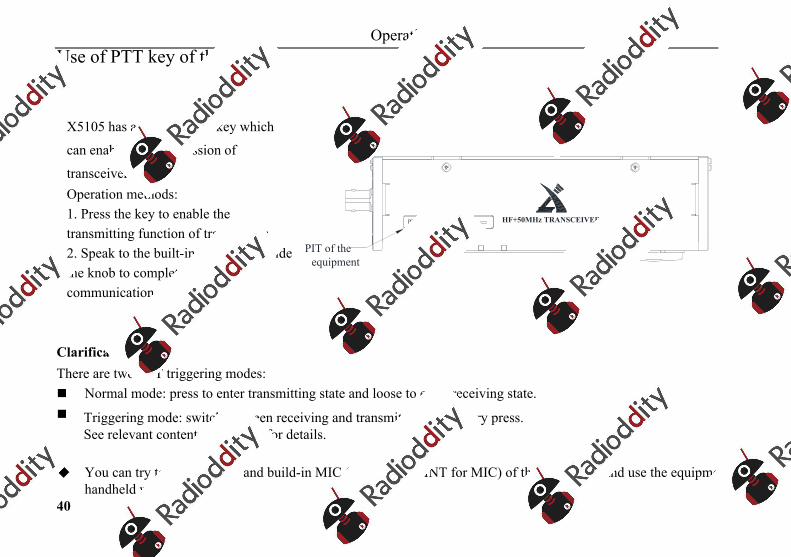
Use of PTT key of the device
Clarifications:There are two PTT triggering modes: Normal mode: press to enter transmitting state and loose to enter receiving state. Triggering mode: switch between receiving and transmitting after every press.
See relevant contents in menu 6 for details.
You can try to use PTT key and build-in MIC (please select INT for MIC) of the equipment and use the equipment inhandheld way.
X5105 has a build-in PTT key which
can enable the transmission of
transceiver.Operation methods:1. Press the key to enable thetransmitting function of transceiver; 2. Speak to the built-in MIC hole besidethe knob to complete the communication.
PTT HF+50MHz TRANSCEIVER DN UP
PIT of the equipment
Operation
41
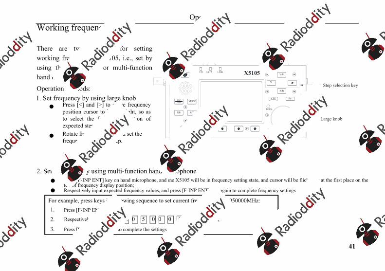
Working frequency settings
2. Set frequency by using multi-function hand microphone Press [F-INP ENT] key on hand microphone, and the X5105 will be in frequency setting state, and cursor will be flickering at the first place on the
left of frequency display position; Respectively input expected frequency values, and press [F-INP ENT] key again to complete frequency settings.
For example, press keys in following sequence to set current frequency as 51.050000MHz: 1. Press [F-INP ENT] firstly;
2. Respectively press 5 1 . 0 5 0 0 0 0 number keys;
3. Press [F-INP ENT] again to complete the settings.
There are two methods for setting working frequency of X5105, i.e., set by using the large knob or multi-function hand microphone.
Operation methods:1. Set frequency by using large knob
Press [<] and [>] to move frequencyposition cursor to left or right, so asto select the frequency position ofexpected step;
Rotate frequency knob and set thefrequency of current step.
X5105T/R DATA LINK
LOCK
PREATT MODE
MENU
V/M
A/B
NB RIT
ATU Po
<
Large knob
Step selection key
Operation
42
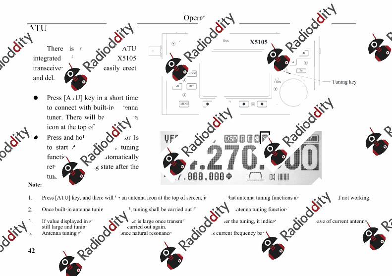
ATU
Note:
1. Press [ATU] key, and there will be an antenna icon at the top of screen, indicating that antenna tuning functions are only enabled and not working.
2. Once built-in antenna tuning is adopted, tuning shall be carried out for one time after antenna tuning function is enabled.
3. If value displayed in standing-wave meter is large once transmitting is enabled after the tuning, it indicates that standing-wave of current antenna is still large and tuning is required to be carried out again.
4. Antenna tuning shall be turned off once natural resonance of antenna reaches current frequency band.
There is an efficient ATU integrated inside the X5105 transceiver to help you easily erect and debug antenna.
Press [ATU] key in a short time to connect with built-in antenna tuner. There will be an antenna icon at the top of screen.
Press and hold [ATU] key for 1s to start ATU automatic tuning functions. IT will automatically return to receiving state after the tuning.
X5105T/R DATA LINK
LOCK
PREATT MODE
MENU
V/M
A/B
NB RIT
ATU Po
<
Tuning key
Operation
43
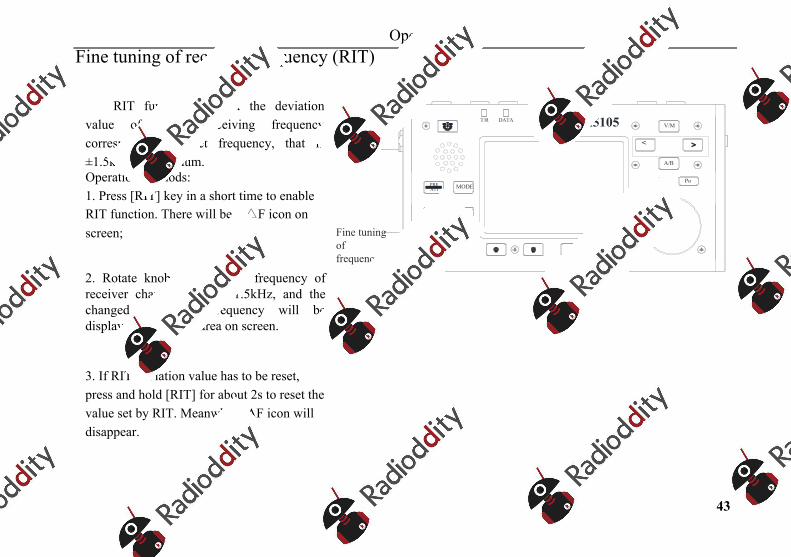
Fine tuning of received frequency (RIT)
RIT function can set the deviation value of actual receiving frequency corresponding to set frequency, that is ±1.5kHz at maximum. Operation methods:1. Press [RIT] key in a short time to enableRIT function. There will be a △F icon on screen;
2. Rotate knob to make the frequency ofreceiver changes within ±1.5kHz, and the changed value of frequency will be displayed in relevant area on screen.
3. If RIT deviation value has to be reset,press and hold [RIT] for about 2s to reset the value set by RIT. Meanwhile, AF icon will disappear.
X5105T/R DATA LINK
LOCK
PREATT MODE
MENU
V/M
A/B
NB RIT
ATU Po
<
Fine tuning of frequency
Operation
44
Automatic gain control (AGC)
Receiving effect can be optimized by adjusting proper AGC speed.
Operation methods:
1. Switch to menu in page 1 and press [AGC] functional key in a short time;
2. AGC functions will be circularly selected according to following sequence:
OFF—SLOW—FAST--AUTO
3. Optimal effect will be obtained by reasonably selecting different AGC speed according to different receiving modes.
SSB/AM mode: SLOW is recommended
CW mode: FAST if recommended
If AUTO is selected, main machine will be automatically switched to a corresponding control speed according to different modes.
If 'AGC-OFF' is selected, AGC system will be closed and S meter will display nothing.
Operation
45
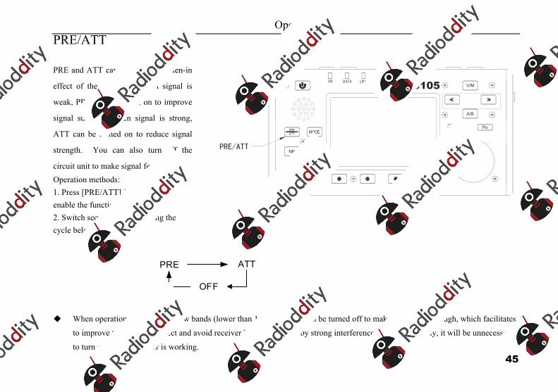
PRE/ATT
When operation in short wave low bands (lower than 10MHz), PRE can be turned off to make signal feedthrough, which facilitates
to improve the receiving effect and avoid receiver blocking caused by strong interference signal. Generally, it will be unnecessary
to turn on PRE if S meter is working.
PRE and ATT can improve the listen-in
effect of the receiver. When signal is
weak, PRE can be turned on to improve
signal strength. When signal is strong,
ATT can be turned on to reduce signal
strength. You can also turn off the
circuit unit to make signal feedthrough. Operation methods:1. Press [PRE/ATT] in a short time toenable the function. 2. Switch sequence by following thecycle below:
X5105T/R DATA LINK
LOCK
PREATT MODE
MENU
V/M
A/B
NB RIT
ATU Po
<
PRE/ATT
ATTPRE
OFF
Operation
46
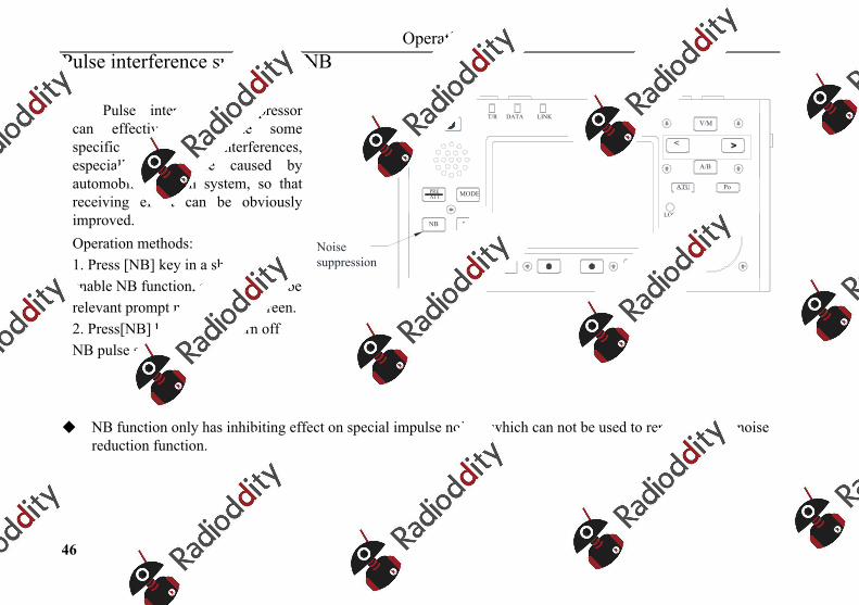
Pulse interference suppressor NB
NB function only has inhibiting effect on special impulse noises, which can not be used to replace digital noise reduction function.
Pulse interference suppressor can effectively eliminate some specific impulse interferences, especially the noise caused by automobile ignition system, so that receiving effect can be obviously improved. Operation methods:1. Press [NB] key in a short time to enable NB function, and there will be relevant prompt messages on screen. 2. Press[NB] key again to turn off NB pulse suppressor.
X5105T/R DATA LINK
LOCK
PREATT MODE
MENU
V/M
A/B
NB RIT
ATU Po
<
Noise suppression
Operation
47
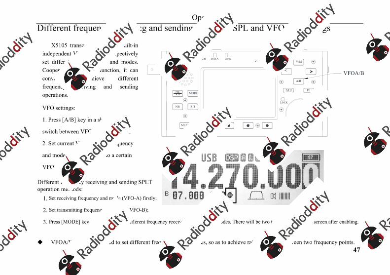
Different frequency receiving and sending operation SPL and VFOA/B settings
Different frequency receiving and sending SPLT operation methods:
1. Set receiving frequency and mode (VFO-A) firstly;
2. Set transmitting frequency and mode (VFO-B);
3. Press [MODE] key to enable/disable different frequency receiving and sending modes. There will be two triangle symbols on screen after enabling.
VFOA/B can be fully used to set different frequencies and modes, so as to achieve raid switching between two frequency points.
X5105 transceiver has two built-in independent VFOs that can respectively set differ tent frequencies and modes. Cooperated with SPL function, it can conveniently achieve different frequency receiving and sending operations.
VFO settings:
1. Press [A/B] key in a short time to
switch between VFO-A and VFO-B;
2. Set current VFO working frequency
and mode when switching to a certain
VFO state.
X5105T/R DATA LINK
LOCK
PREATT MODE
MENU
V/M
A/B
NB RIT
ATU Po
< VFOA/B
Operation
48
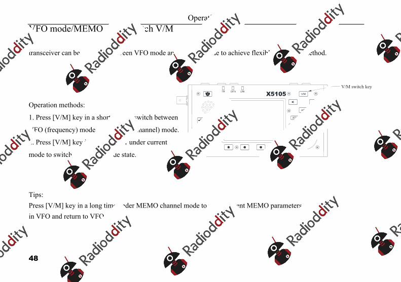
VFO mode/MEMO mode switch V/M
transceiver can be switched between VFO mode and MEMO mode to achieve flexible operation method.
Operation methods:
1. Press [V/M] key in a short time to switch between
VFO (frequency) mode and MEMO (channel) mode.
2. Press [V/M] key in a short timer under current
mode to switch to another mode state.
Tips: Press [V/M] key in a long time under MEMO channel mode to write current MEMO parameters in VFO and return to VFO mode.
X5105T/R DATA LINK
LOCK
PREATT MODE
MENU
V/M
A/B
NB RIT
ATU Po
<
V/M switch key
Operation
49
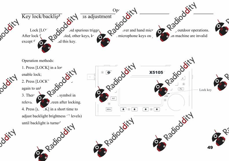
Key lock/backlight brightness adjustment Lock
Lock [LOCK] key to avoid spurious triggering of transceiver and hand microphone during outdoor operations. After lock function is enabled, other keys, knobs and Hand microphone keys on panel of main machine are invalid except for PTT keys and this key.
Operation methods:
1. Press [LOCK] in a long time to
enable lock;
2. Press [LOCK] in a long time
again to unlock.
3. There will be a lock symbol in
relevant area of screen after locking.
4. Press [LOCK] in a short time to
adjust backlight brightness (5 levels)
until backlight is turned off.
X5105T/R DATA LINK
LOCK
PREATT MODE
MENU
V/M
A/B
NB RIT
ATU Po
<
Lock key
Operation
50
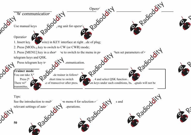
CW communication
Use manual keys or external keying unit for operations.
Operation methods:1. Insert keys (three-wire) in KEY interface at right side of plug; 2. Press [MODE] key to switch to CW (or CWR) mode; 3. Press [MENU] key in a short time to switch to the menu in page 4, and then set parameters of relevant telegram keys and QSK. 4. Press telegram key to enable CW communication.
Trainer modeYou can take X5105 as a CW code trainer in following methods:
Press [MENU] key in a short time to switch to menu in page 4 and select QSK function as 'OFF'. There will be CW sidetone of transceiver after pressing telegram keys under such conditions, but signals will not be transmitted externally.
Tips:See the introduction to multi-function menu 4 for selection of telegram keys and relevant settings of auto keys or other operations.

Operation
51
Preset message editing and sending MSG1~MSG10
Main machine of X5105 provides a memory for 10 groups of preset telegraph texts to achieve automatic calling under CW/PSK/RTTY mode.
Operation methods:1. See the introduction to multi-function menu 3 for details on operation and editing method of preset telegraph texts. 2. in #5-2 menu, press [MSG] key in a short time to select the telegraph texts to be sent, and then press XFC key on multi-function hand microphone to send them.
Operation
52
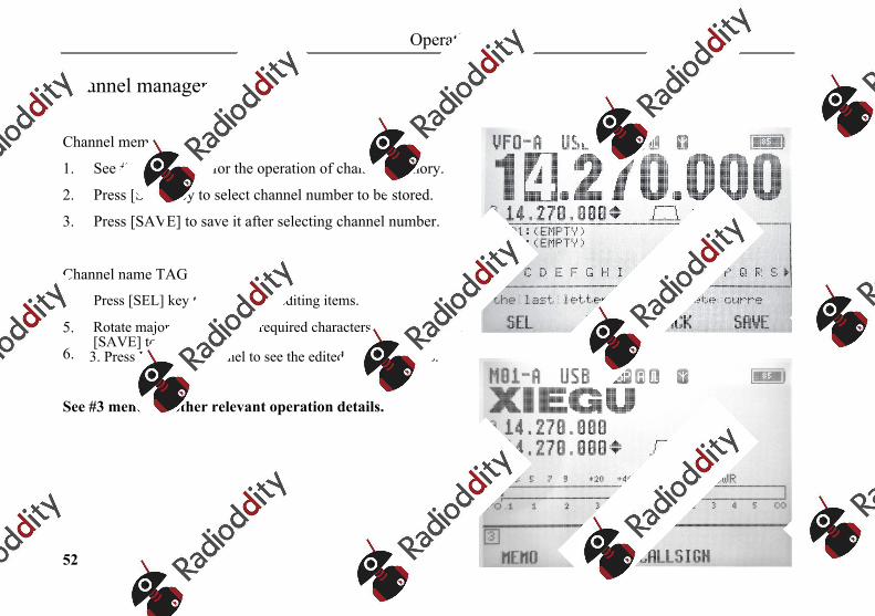
Channel manager
Channel memory (MEMO)
1. See #3-1 submenu for the operation of channel memory.
2. Press [SEL] key to select channel number to be stored.
3. Press [SAVE] to save it after selecting channel number.
Channel name TAG
4. Press [SEL] key to select TAG editing items.
5. Rotate major knob to select required characters, and then press [SAVE] to save them.
6. 3. Press V/M key on panel to see the edited channel names.
See #3 menu for other relevant operation details.
Operation
53
Amateur radio data communications by connecting with computer
X5105 transceiver can be connected with computer and complete all kinds of data communications under the help of computer softwares.
Operation and connection methods:
1. Connect computer audio output/input to X5105 from ACC interface (MINI-DIN8).
2. Insert attached data cable into COM (or CIV) interface, connect X5105 with computer, and ensure that drive of
computer of data cable is correctly installed and PC software can control the X5105 transceiver;
3. Adjust the volume of X5105 and input/output volume of ACC interface to a proper level and observe software
interface to avoid communication failure caused by excessive audio range.
4. Select corresponding working modes, i.e., carry out data communication.
Radio and computer must be well grounded to avoid interference, and EMC magnet ring shall be installed for data cable and audio cable at the position close to main machine of radio to greatest extent.
Operation
54
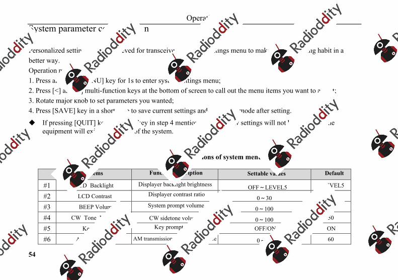
System parameter configuration
Personalized settings can be achieved for transceiver in system settings menu to make it fit your using habit in a better way. Operation methods:1. Press and hold [MENU] key for 1s to enter system settings menu; 2. Press [<] and [>] multi-function keys at the bottom of screen to call out the menu items you want to adjust; 3. Rotate major knob to set parameters you wanted; 4. Press [SAVE] key in a short time to save current settings and exit menu mode after setting.
If pressing [QUIT] key in a short key in step 4 mentioned above, new settings will not be saved and the equipment will exit menu mode of the system.
Descriptions of system menu
Menu items Function description Settable values Default
#1 LCD Backlight Displayer backlight brightness OFF~LEVEL5 LEVEL5
#2 LCD Contrast Displayer contrast ratio 0~30 30
#3 BEEP Volum System prompt volume 0~100 50
#4 CW Tone Volum CW sidetone volume 0~100 50
#5 Key BEEP Key prompt tone OFF/ON ON
#6 AM Mod Level AM transmission modulation degree 0~63 60
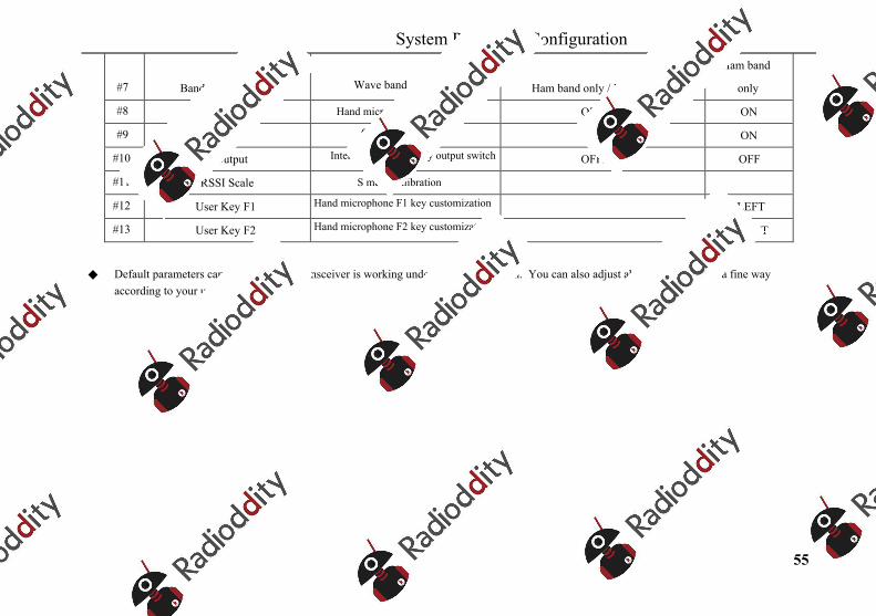
System Parameter Configuration
55
#7 Band Stack Mode Wave band group mode Ham band only / Full band
Ham band
only
#8 MIC Bias Hand microphone bias settings OFF/ON ON
#9 Charger Charging switch OFF/ON ON
#10 IF Output Intermediate frequency output switch OFF/ON OFF
#11 RSSI Scale S meter calibration
#12 User Key F1 Hand microphone F1 key customization LEFT
#13 User Key F2 Hand microphone F2 key customization RIGHT
Default parameters can ensure that the transceiver is working under a goods condition. You can also adjust above parameters in a fine way according to your using habits.
Operation
56
Computer control instructions
X5105 adopts standard CIV instruction sets. You can remotely control the transceiver based on standard instructions of the instruction set or configure control instructions of other softwares, so as to achieve the control on X5105.
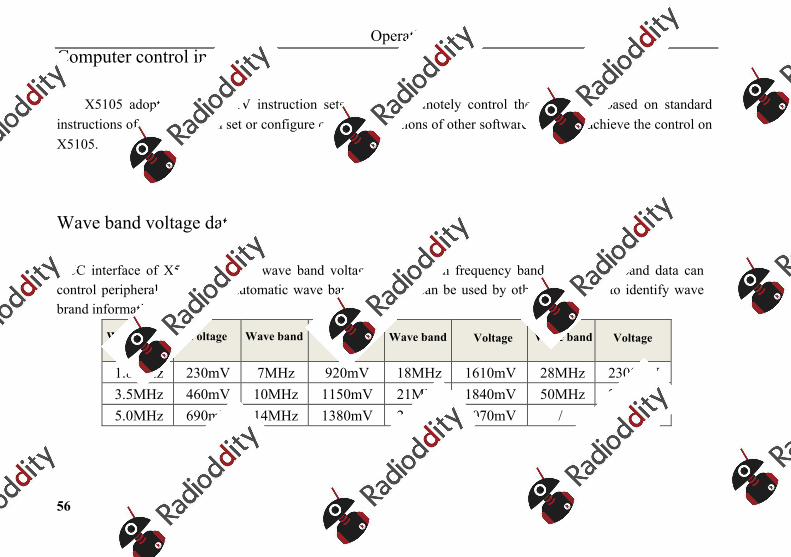
Wave band voltage data
ACC interface of X5105 provides wave band voltage data of each frequency band. The wave band data can control peripherals to achieve automatic wave band switch or can be used by other equipment to identify wave brand information.
Wave band Voltage Wave band Voltage Wave band Voltage Wave band Voltage
1.8MHz 230mV 7MHz 920mV 18MHz 1610mV 28MHz 2300mV 3.5MHz 460mV 10MHz 1150mV 21MHz 1840mV 50MHz 2530mV 5.0MHz 690mV 14MHz 1380mV 24MHz 2070mV / /
Indicators
57
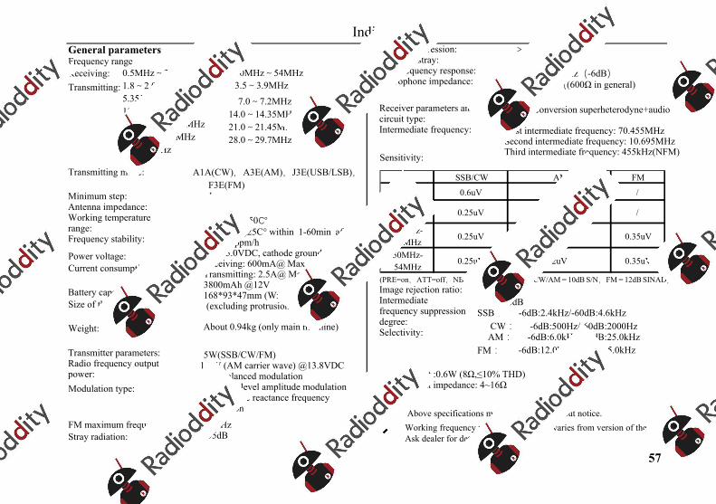
General parametersFrequency rangeReceiving:Transmitting:
50MHz~54MHz 3.5~3.9MHz
7.0~7.2MHz 14.0~14.35MHz 21.0~21.45MHz 28.0~29.7MHz
0.5MHz~30MHz 1.8~2.0MHz 5.3515~5.3665MHz 10.1~10.15MHz 18.068~18.168MHz 24.89~24.99MHz 50~54MHz
Transmitting mode: A1A(CW),A3E(AM),J3E(USB/LSB),F3E(FM) 1Hz 50Ω -10℃ ~ +50℃
Minimum step: Antenna impedance: Working temperature range: Frequency stability:
Power voltage:Current consumption:
Battery capacity:Size of the equipment:
±4ppm @25C° within 1-60min after startup: 1ppm/h 9.0~15.0VDC, cathode grounding Receiving: 600mA@ Max Transmitting: 2.5A@ Max 3800mAh @12V 168*93*47mm (WxHxT)
(excluding protrusions)
Weight: About 0.94kg (only main machine)
Transmitter parameters: Radio frequency output power: Modulation type:
5W(SSB/CW/FM)1.5W (AM carrier wave) @13.8VDCSSB: balanced modulationAM: Low level amplitude modulationFM: variable reactance frequency modulation
FM maximum frequency offset:Stray radiation:
±5kHz -55dB
>40dB >50dB
Carrier suppression: Sideband stray: SSB frequency response: Microphone impedance:
400Hz-2800Hz(-6dB) 200~10k((600Ω in general)
Receiver parameters and circuit type: Intermediate frequency:
Double conversion superheterodyne+audio DSPFirst intermediate frequency: 70.455MHzSecond intermediate frequency: 10.695MHzThird intermediate frequency: 455kHz(NFM)Sensitivity:
(PRE=on,ATT=off,NB=off,NR=off,SSB/CW/AM = 10dB S/N,FM = 12dB SINAD) 70dB Image rejection ratio:
Intermediate frequency suppression degree: Selectivity:
60dB SSB: -6dB:2.4kHz/-60dB:4.6kHz
CW: -6dB:500Hz/-60dB:2000Hz AM: -6dB:6.0kHz/-60dB:25.0kHz
FM: -6dB:12.0kHz/-60dB:25.0kHz
Audio output :0.6W (8Ω,≤10% THD)Audio output impedance: 4~16Ω
Above specifications may be changed without notice.
Working frequency range of transceiver varies from version of the equipment. Ask dealer for details.
SSB/CW AM FM≤1.8MHz 0.6uV 10uV /
1.8MHz-28MHz
0.25uV 2uV /
28MHz-30MHz
0.25uV 2uV 0.35uV
50MHz-54MHz
0.25uV 2uV 0.35uV
Accessories
58
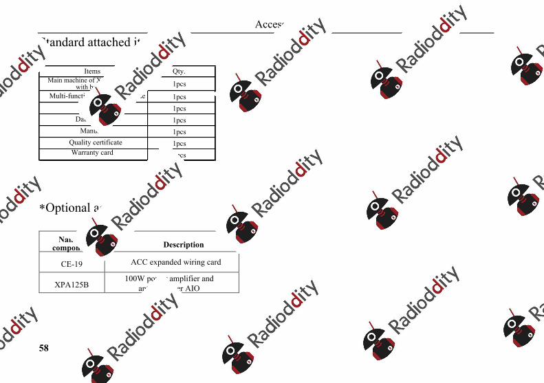
Standard attached items
*Optional accessories
Name of components Description
CE-19 ACC expanded wiring card
XPA125B 100W power amplifier and
antenna tuner AIO
Items Qty.Main machine of X5105 (provided
with batteries) 1pcsMulti-function hand microphone 1pcs
Power line 1pcsData cable 1pcs
Manual 1pcsQuality certificate 1pcsWarranty card 1pcs
Appendix
59
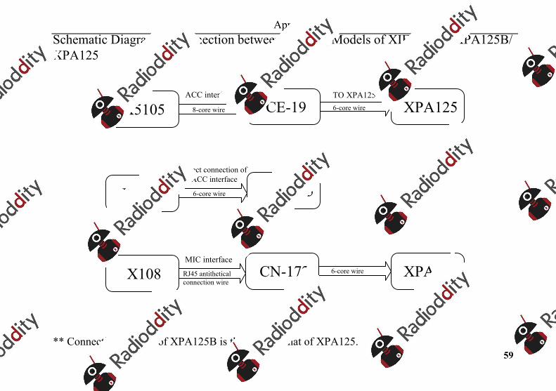
Schematic Diagram of Connection between Existing Models of XIEGU and XPA125B/XPA125
** Connection method of XPA125B is the same as that of XPA125.
X5105 CE-19 XPA1258-core wire
ACC interface6-core wire
TO XPA125
X108G XPA1256-core wire
Direct connection of ACC interface
X108 CN-172 XPA125RJ45 antithetical connection wire
MIC interface6-core wire
Appendix
60
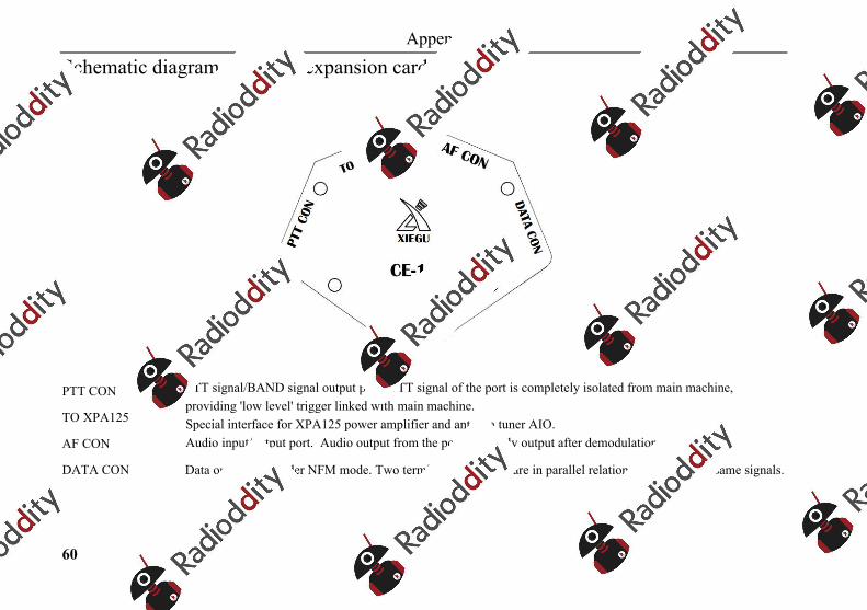
Schematic diagram of CE-19 expansion card interface
PTT CON
TO XPA125
AF CON
PTT signal/BAND signal output port. PTT signal of the port is completely isolated from main machine, providing 'low level' trigger linked with main machine. Special interface for XPA125 power amplifier and antenna tuner AIO. Audio input/output port. Audio output from the port is directly output after demodulation without filter.
DATA CON Data output port under NFM mode. Two terminals of the port are in parallel relationship, outputting same signals.

Copyright Statement
61
All Rights Reserved 2019
Chongqing Xiegu Technology Co., Ltd. reserves all rights of the manual. Any part of the manual shall
not be copied without permission.
V3.0
1010160203-C


![Wiro A5Landscape Template · 4 DelugeOfficialManual 3 Sequencer NOTES SETTINGARECORDINGCOUNT-IN 1. Press[SHIFT]+press(SELECT)toaccessthesettingsmenu. 2. Turn(SELECT)tohighlight‘rECo’-recording,in](https://img.pdfslide.net/doc/110x75/5fb8cb6945c0884d5a19e9a1/wiro-a5landscape-template-4-delugeofficialmanual-3-sequencer-notes-settingarecordingcount-in.jpg)


![DEH-1800UBG - caraudio-image.ru · En 5 English 2 Turn the M.C. dial to select [SYSTEM], then press to confirm. 3 Turn the M.C. dial to select [DEMO OFF], then press to confirm. 4](https://img.pdfslide.net/doc/110x75/5b146d2c7f8b9a347c8d14ac/deh-1800ubg-caraudio-imageru-en-5-english-2-turn-the-mc-dial-to-select.jpg)