Embed Size (px)
Citation preview

HFCutilized
R410A
MUZ-FE09NAMUZ-FE12NAMUZ-FE09NA - 1
MUZ-FE12NA1
MUZ-FE09NAHMUZ-FE12NAH
TM
OUTDOOR UNIT
SERVICE MANUAL
Models
MUZ-FE09NAMUZ-FE09NA - 1
MUZ-FE09NAHMUZ-FE12NAMUZ-FE12NA1MUZ-FE12NAHMUZ-FE18NA
No. OBH543REVISED EDITION-F
Please void OBH543 REVISED EDITION-E.
Revision F:• The descriptions of the expansion valve
coil have been corrected. (10-4.)• Some descriptions have been modified.
Indoor unit service manualMSZ-FE•NA Series (OBH542)
CONTENTS1. TECHNICAL CHANGES ··································· 22. PART NAMES AND FUNCTIONS ····················· 33. SPECIFICATION ················································ 44. OUTLINES AND DIMENSIONS ························ 65. WIRING DIAGRAM ············································ 76. REFRIGERANT SYSTEM DIAGRAM ··············· 97. DATA ·································································118. ACTUATOR CONTROL ··································· 189. SERVICE FUNCTIONS ··································· 19
10. TROUBLESHOOTING ····································· 1911. DISASSEMBLY INSTRUCTIONS ···················· 38
PARTS CATALOG (OBB543)
NOTE: RoHS compliant products have <G> mark on the spec name plate.

2
1 TECHNICAL CHANGES
MUZ-FE09NAMUZ-FE12NAMUZ-FE18NA1. New model
Revision A:• MUZ-FE18NA has been added.
Revision B:• MUZ-FE09NA - 1 and MUZ-FE12NA1 have been added.
Use the specifi ed refrigerant onlyNever use any refrigerant other than that specified.Doing so may cause a burst, an explosion, or fire when the unit is being used, serviced, or disposed of.Correct refrigerant is specified in the manuals and on the spec labels provided with our products.We will not be held responsible for mechanical failure, system malfunction, unit breakdown or accidents caused by failure to follow the instructions.
MUZ-FE09NA MUZ-FE09NA - 1
MUZ-FE12NA MUZ-FE12NA11. Compressor has been changed.2. Inverter P.C. board has been changed.
Revision C:• Specification has been corrected.[Capacity Rated Capacity Rated (Maximum), Power consumption Rated Power consumption Rated (Maximum)]
Revision D:• MUZ-FE09NAH and MUZ-FE12NAH have been added.
MUZ-FE09NA - 1 MUZ-FE09NAHMUZ-FE12NA1 MUZ-FE12NAH1. Defrost heater has been added.2. Inverter P.C. board has been changed.
Revision E:• The formula for calculating the additional refrigerant charge has been corrected.
Revision F:• The descriptions of the expansion valve coil have been corrected. (10-4.)• Some descriptions have been modified.
OBH543F
3
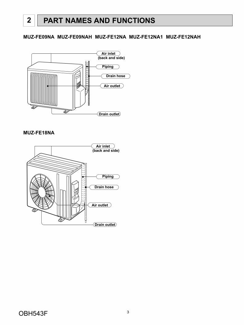
MUZ-FE09NA MUZ-FE09NAH MUZ-FE12NA MUZ-FE12NA1 MUZ-FE12NAH
Piping
Air outlet
Drain outlet
Air inlet(back and side)
Drain hose
MUZ-FE18NA
Piping
Air outlet
Drain outlet
Air inlet(back and side)
Drain hose
PART NAMES AND FUNCTIONS2
OBH543F
4
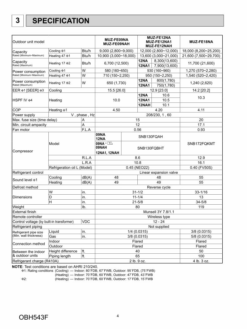
3 SPECIFICATION
Outdoor unit model MUZ-FE09NAMUZ-FE09NAH
MUZ-FE12NAMUZ-FE12NA1MUZ-FE12NAH
MUZ-FE18NA
Capacity Rated (Minimum~Maximum)
Cooling 1 Btu/h 9,000 (2,800~9,000) 12,000 (2,800~12,000) 18,000 (8,200~25,200)Heating 47 1 Btu/h 10,900 (3,000~18,000) 13,600 (3,000~21,000) 21,600 (7,500~29,700)
Capacity Rated (Maximum)
Heating 17 2 Btu/h 6,700 (12,500) 12NA 8,300(13,600) 11,700 (21,600)12NA1 7,900(13,600)Power consumption Rated (Minimum~Maximum)
Cooling 1 W 580 (160~650) 930 (160~960) 1,270 (570~2,280)Heating 47 1 W 710 (150~2,250) 950 (150~2,250) 1,540 (520~2,420)
Power consumption Rated (Maximum)
Heating 17 2 W 650 (1,730) 12NA 800(1,780) 1,240 (2,620)12NA1 750(1,780)EER 1 [SEER] 3 Cooling 15.5 [26.0] 12.9 [23.0] 14.2 [20.2]
HSPF IV 4 Heating 10.012NA 10.6 10.312NA1 10.512NAH 10.1
COP Heating 1 4.50 4.20 4.11Power supply V , phase , Hz 208/230, 1 , 60Max. fuse size (time delay) A 15 20Min. circuit ampacity A 12 17.1Fan motor F.L.A 0.56 0.93
Compressor
Model
09NA12NA SNB130FQAH
SNB172FQKMT09NA - 1 , 09NAH12NA1, 12NAH
SNB130FQBHT
R.L.A 8.6 12.9L.R.A 10.8 16.1
Refrigeration oil L (Model) 0.45 (NEO22) 0.40 (FV50S)Refrigerant control Linear expansion valve
Sound level 1 Cooling dB(A) 48 48 55Heating dB(A) 49 49 55
Defrost method Reverse cycle
Dimensions W in. 31-1/2 33-1/16D in. 11-1/4 13H in. 21-5/8 34-5/8
Weight Ib. 80 119External fi nish Munsell 3Y 7.8/1.1Remote controller Wireless typeControl voltage (by built-in transformer) VDC 12 - 24Refrigerant piping Not suppliedRefrigerant pipe size (Min. wall thickness)
Liquid in. 1/4 (0.0315) 3/8 (0.0315)Gas in. 3/8 (0.0315) 5/8 (0.0315)
Connection method Indoor Flared FlaredOutdoor Flared Flared
Between the indoor & outdoor units
Height difference ft. 40 50Piping length ft. 65 100
Refrigerant charge (R410A) 2 lb. 9 oz. 4 lb. 3 oz.NOTE: Test conditions are based on AHRI 210/240. 1: Rating conditions (Cooling) — Indoor: 80˚FDB, 67˚FWB, Outdoor: 95˚FDB, (75˚FWB) (Heating) — Indoor: 70˚FDB, 60˚FWB, Outdoor: 47˚FDB, 43˚FWB 2: (Heating) — Indoor: 70˚FDB, 60˚FWB, Outdoor: 17˚FDB, 15˚FWB
OBH543F
5
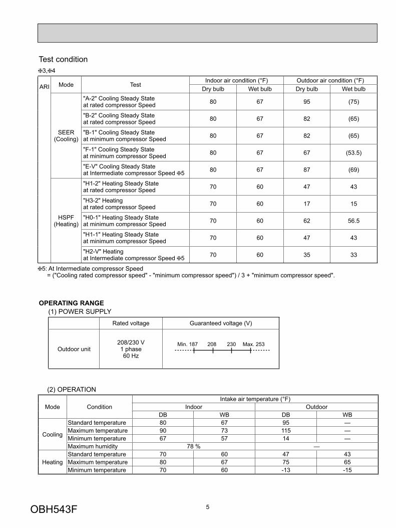
Test condition
ARI Mode Test Indoor air condition (°F) Outdoor air condition (°F)
Dry bulb Wet bulb Dry bulb Wet bulb
SEER (Cooling)
"A-2" Cooling Steady State at rated compressor Speed 80 67 95 (75)
"B-2" Cooling Steady State at rated compressor Speed 80 67 82 (65)
"B-1" Cooling Steady State at minimum compressor Speed 80 67 82 (65)
"F-1" Cooling Steady State at minimum compressor Speed 80 67 67 (53.5)
"E-V" Cooling Steady State at Intermediate compressor Speed 5 80 67 87 (69)
HSPF (Heating)
"H1-2" Heating Steady State at rated compressor Speed 70 60 47 43
"H3-2" Heating at rated compressor Speed 70 60 17 15
"H0-1" Heating Steady State at minimum compressor Speed 70 60 62 56.5
"H1-1" Heating Steady State at minimum compressor Speed 70 60 47 43
"H2-V" Heating at Intermediate compressor Speed 5 70 60 35 33
5: At Intermediate compressor Speed = ("Cooling rated compressor speed" - "minimum compressor speed") / 3 + "minimum compressor speed".
3, 4
(2) OPERATION
Mode ConditionIntake air temperature (°F)
Indoor OutdoorDB WB DB WB
Cooling
Standard temperature 80 67 95 — Maximum temperature 90 73 115 — Minimum temperature 67 57 14 — Maximum humidity 78 % —
HeatingStandard temperature 70 60 47 43Maximum temperature 80 67 75 65Minimum temperature 70 60 -13 -15
OPERATING RANGE(1) POWER SUPPLY
Rated voltage Guaranteed voltage (V)
Outdoor unit 208/230 V 1 phase 60 Hz
Min. 187 208 230 Max. 253
OBH543F
6
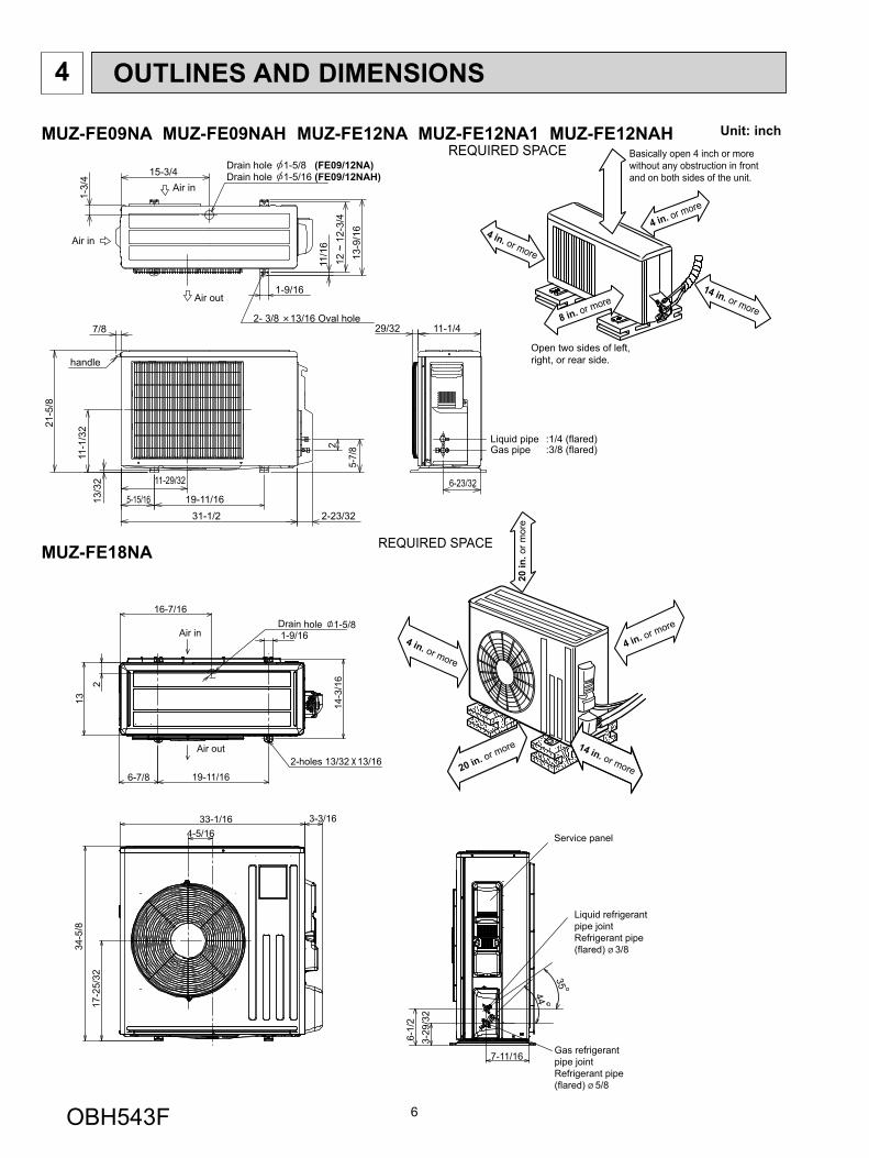
OUTLINES AND DIMENSIONS4
Unit: inchMUZ-FE09NA MUZ-FE09NAH MUZ-FE12NA MUZ-FE12NA1 MUZ-FE12NAH
Liquid pipe :1/4 (flared)Gas pipe :3/8 (flared)
6-23/32
2
5-7/
8
2-23/32
1-3/
4 15-3/4
12 ~
12-
3/4
13-9
/16
11/1
6
1-9/16
7/8
21-5
/8
11-1
/32
13/3
2
31-1/219-11/165-15/16
11-29/32
29/32 11-1/4
Air in
handle
Air in
Air out
2- 3/8 13/16 Oval hole
Drain hole 1-5/8 (FE09/12NA)Drain hole 1-5/16 (FE09/12NAH)
REQUIRED SPACE Basically open 4 inch or more without any obstruction in front and on both sides of the unit.
14 in. or more8 in. or more
4 in. or more
4 in. or more
Open two sides of left, right, or rear side.
MUZ-FE18NA
16-7/16
1-9/161-5/8Drain hole
6-7/8 19-11/16
13
2
Air in
Air out2-holes 13/32 13/16
14-3
/16
33-1/164-5/16
3-3/16
34-5
/8
17-2
5/32
Service panel
3-29
/32
6-1/
2
7-11/16
35
44
Liquid refrigerantpipe jointRefrigerant pipe(flared) Ø 3/8
Gas refrigerantpipe jointRefrigerant pipe(flared) Ø 5/8
14 in. or more
4 in. or more
REQUIRED SPACE20
in. o
r mor
e
4 in. or more
20 in. or more
OBH543F
7
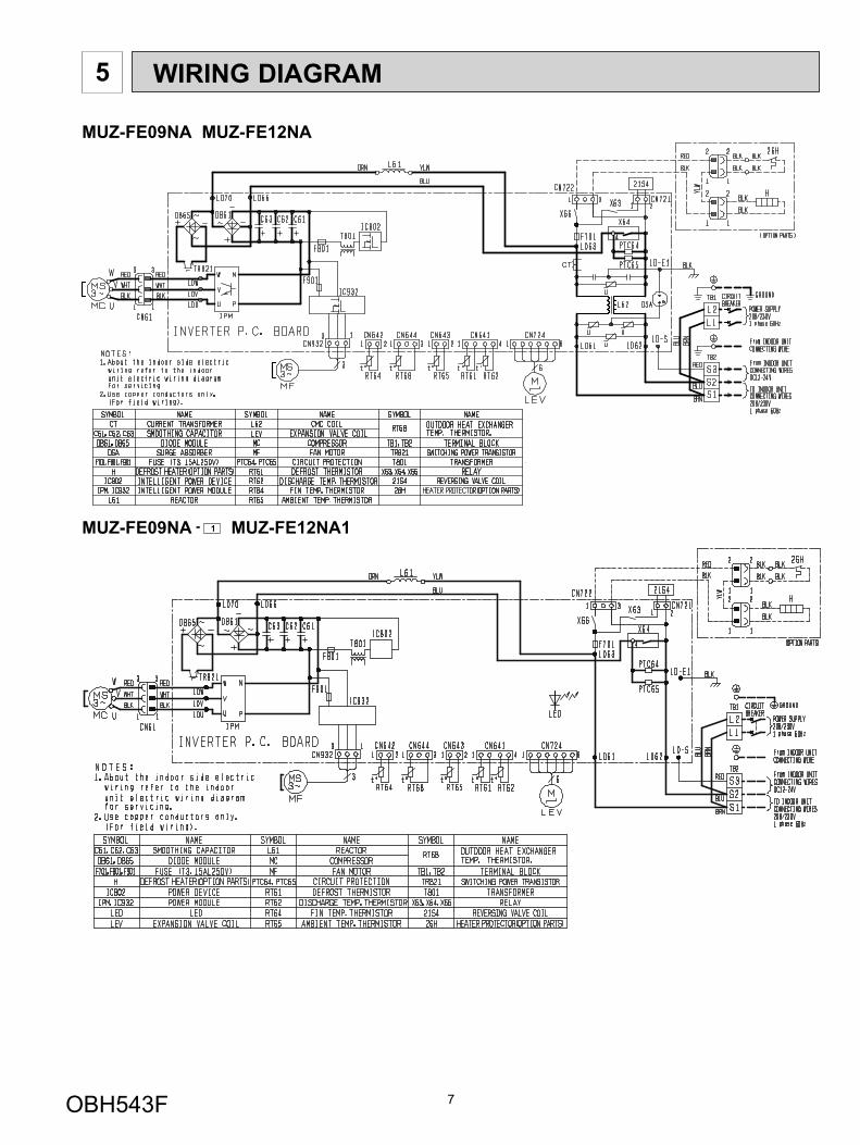
5 WIRING DIAGRAM
MUZ-FE09NA MUZ-FE12NA
MUZ-FE09NA - 1 MUZ-FE12NA1
OBH543F
8
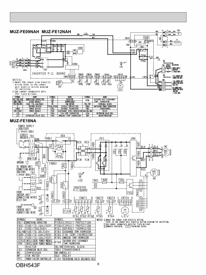
MUZ-FE18NA
MUZ-FE09NAH MUZ-FE12NAH
OBH543F
9
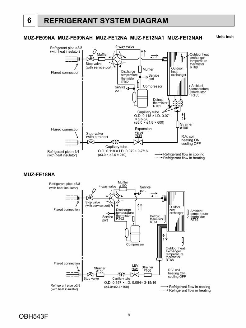
6 REFRIGERANT SYSTEM DIAGRAM
Unit: inchMUZ-FE09NA MUZ-FE09NAH MUZ-FE12NA MUZ-FE12NA1 MUZ-FE12NAH
OutdoorheatexchangerFlared connection
DefrostthermistorRT61
DischargetemperaturethermistorRT62
Serviceport
Serviceport
Flared connectionStop valve(with strainer)
Stop valve(with service port)
Refrigerant flow in cooling
Compressor
4-way valve
Refrigerant flow in heating
Refrigerant pipe ø3/8(with heat insulator)
Refrigerant pipe ø1/4(with heat insulator)
R.V. coilheating ONcooling OFF
Strainer#100
Capillary tube
Expansionvalve
Ambient temperature thermistorRT65
Muffler
O.D. 0.118 × I.D. 0.071 × 23-5/8(ø3.0 × ø1.8 × 600)
Capillary tubeO.D. 0.118 × I.D. 0.079× 9-7/16(ø3.0 × ø2.0 × 240)
Outdoor heatexchanger temperature thermistorRT68Muffler
MUZ-FE18NA
Outdoorheatexchanger
Flared connection
DefrostthermistorRT61
DischargetemperaturethermistorRT62
Flared connection
Stop valve
Stop valve(with service port)
Capillary tubeO.D. 0.157 × I.D. 0.094× 3-15/16(ø4.0×ø2.4×100)
Compressor
4-way valveRefrigerant pipe ø5/8(with heat insulator)
Refrigerant pipe ø3/8(with heat insulator)
LEVR.V. coilheating ONcooling OFF
Muffler#100
Strainer#100
Outdoor heat exchanger temperaturethermistorRT68
AmbienttemperaturethermistorRT65
Strainer#100
Refrigerant flow in coolingRefrigerant flow in heating
Serviceport
Serviceport
OBH543F
10
Max. Length A
Max. Heightdifference
B
Indoorunit
Outdoor unit
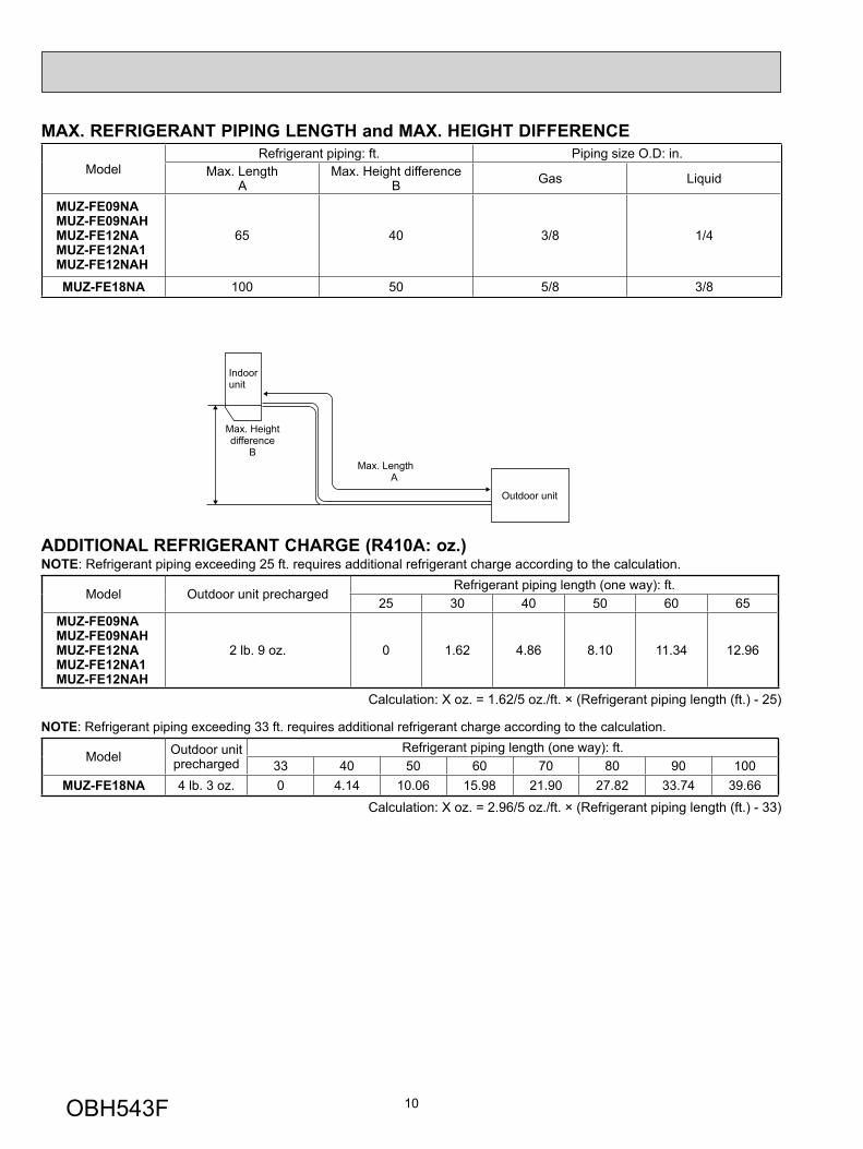
MAX. REFRIGERANT PIPING LENGTH and MAX. HEIGHT DIFFERENCE
Model Refrigerant piping: ft. Piping size O.D: in.
Max. Length A
Max. Height difference B Gas Liquid
MUZ-FE09NAMUZ-FE09NAHMUZ-FE12NAMUZ-FE12NA1MUZ-FE12NAH
65 40 3/8 1/4
MUZ-FE18NA 100 50 5/8 3/8
ADDITIONAL REFRIGERANT CHARGE (R410A: oz.)NOTE: Refrigerant piping exceeding 25 ft. requires additional refrigerant charge according to the calculation.
Model Outdoor unit precharged Refrigerant piping length (one way): ft.
25 30 40 50 60 65MUZ-FE09NAMUZ-FE09NAHMUZ-FE12NAMUZ-FE12NA1MUZ-FE12NAH
2 lb. 9 oz. 0 1.62 4.86 8.10 11.34 12.96
Calculation: X oz. = 1.62/5 oz./ft. × (Refrigerant piping length (ft.) - 25)
NOTE: Refrigerant piping exceeding 33 ft. requires additional refrigerant charge according to the calculation.
Model Outdoor unit precharged
Refrigerant piping length (one way): ft.33 40 50 60 70 80 90 100
MUZ-FE18NA 4 lb. 3 oz. 0 4.14 10.06 15.98 21.90 27.82 33.74 39.66
Calculation: X oz. = 2.96/5 oz./ft. × (Refrigerant piping length (ft.) - 33)
OBH543F

11
DATA7
MUZ-FE09NA MUZ-FE09NAH MUZ-FE12NA MUZ-FE12NA1 MUZ-FE12NAH MUZ-FE18NA7-1. PERFORMANCE DATA 1) COOLING CAPACITY
Model Indoor air Outdoor intake air DB temperature (˚F)
IWB (˚F) 75 85 95 105 115TC SHC TPC TC SHC TPC TC SHC TPC TC SHC TPC TC SHC TPC
MUZ-FE09NAMUZ-FE09NAH
71 11.0 6.9 0.58 10.3 6.5 0.63 9.7 6.1 0.68 9.0 5.6 0.72 8.3 5.2 0.7567 10.4 7.9 0.55 9.7 7.4 0.60 9.0 6.8 0.65 8.4 6.4 0.69 7.7 5.8 0.7263 9.8 8.8 0.52 9.1 8.1 0.58 8.5 7.6 0.62 7.7 6.9 0.66 7.0 6.3 0.69
MUZ-FE12NAMUZ-FE12NA1MUZ-FE12NAH
71 14.7 8.8 0.85 13.7 8.2 0.94 12.9 7.7 1.01 12.0 7.2 1.06 11.0 6.6 1.1067 13.9 10.2 0.81 13.0 9.5 0.89 12.0 8.8 0.96 11.2 8.1 1.02 10.3 7.5 1.0763 13.1 11.3 0.77 12.1 10.5 0.85 11.3 9.7 0.92 10.3 8.9 0.98 9.4 8.1 1.02
MUZ-FE18NA71 22.1 15.6 1.13 20.6 14.6 1.24 19.4 13.7 1.33 18.0 12.7 1.40 16.6 11.7 1.4667 20.9 17.5 1.07 19.4 16.3 1.17 18.0 15.1 1.27 16.7 14.1 1.35 15.4 12.9 1.4163 19.6 19.1 1.02 18.2 17.7 1.12 16.9 16.5 1.21 15.4 15.0 1.30 14.0 13.7 1.35
NOTE: 1. IWB : Intake air wet-bulb temperature TC : Total Capacity (x103 Btu/h)SHC : Sensible Heat Capacity (x103 Btu/h) TPC : Total Power Consumption (kW)
2. SHC is based on 80˚F of indoor Intake air DB temperature.
2) COOLING CAPACITY CORRECTIONSRefrigerant piping length (one way: ft.)
25 (std.) 40 65 100MUZ-FE09NAMUZ-FE09NAHMUZ-FE12NAMUZ-FE12NA1MUZ-FE12NAH
1.0 0.954 0.878 -
MUZ-FE18NA 1.0 0.954 0.878 0.771
3) HEATING CAPACITY
Model Indoor air Outdoor intake air WB temperature (˚F)
IDB (˚F) 5 15 25 35 43 45 55TC TPC TC TPC TC TPC TC TPC TC TPC TC TPC TC TPC
MUZ-FE09NA75 4.8 0.44 6.3 0.56 7.9 0.66 9.4 0.73 10.6 0.77 11.0 0.78 12.4 0.8170 5.2 0.42 6.7 0.54 8.2 0.64 9.6 0.71 10.9 0.75 11.2 0.77 12.7 0.8065 5.5 0.41 6.9 0.52 8.6 0.62 10.0 0.69 11.2 0.73 11.6 0.74 13.0 0.78
MUZ-FE09NAH75 4.8 0.57 6.3 0.69 7.9 0.79 9.4 0.73 10.6 0.77 11.0 0.78 12.4 0.8170 5.2 0.55 6.7 0.67 8.2 0.77 9.6 0.71 10.9 0.75 11.2 0.77 12.7 0.8065 5.5 0.54 6.9 0.65 8.6 0.75 10.0 0.69 11.2 0.73 11.6 0.74 13.0 0.78
MUZ-FE12NAMUZ-FE12NA1
75 6.0 0.58 7.9 0.73 9.9 0.86 11.8 0.96 13.3 1.00 13.7 1.02 15.5 1.0670 6.5 0.55 8.4 0.71 10.2 0.84 12.0 0.93 13.6 0.98 14.0 1.00 15.8 1.0465 6.8 0.53 8.6 0.68 10.7 0.81 12.4 0.91 14.0 0.96 14.4 0.97 16.2 1.02
MUZ-FE12NAH75 6.0 0.71 7.9 0.86 9.9 0.99 11.8 0.96 13.3 1.00 13.7 1.02 15.5 1.0670 6.5 0.68 8.4 0.84 10.2 0.97 12.0 0.93 13.6 0.98 14.0 1.00 15.8 1.0465 6.8 0.66 8.6 0.81 10.7 0.94 12.4 0.91 14.0 0.96 14.4 0.97 16.2 1.02
MUZ-FE18NA75 9.5 0.91 12.5 1.15 15.7 1.35 18.7 1.50 21.1 1.58 21.7 1.60 24.6 1.6670 10.3 0.87 13.3 1.11 16.2 1.32 19.1 1.46 21.6 1.54 22.2 1.57 25.2 1.6365 10.8 0.83 13.6 1.06 17.0 1.27 19.8 1.42 22.2 1.50 22.9 1.52 25.7 1.60
NOTE: 1. IDB : Intake air dry-bulb temperatureTC : Total Capacity (x103 Btu/h) TPC : Total Power Consumption (kW)
2. Above data is for heating operation without any frost.
How to operate with fixed operational frequency of the compressor.1. Press the EMERGENCY OPERATION switch on the front of the indoor unit, and select either EMERGENCY COOL
mode or EMERGENCY HEAT mode before starting to operate the air conditioner.2. The compressor starts with operational frequency.3. The fan speed of the indoor unit is High.4. This operation continues for 30 minutes.5. In order to release this operation, press the EMERGENCY OPERATION switch twice or once, or press any button on
the remote controller.
OBH543F
12
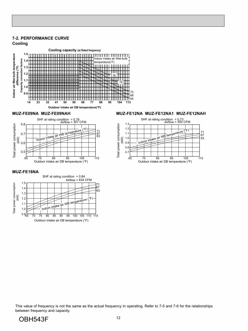
7-2. PERFORMANCE CURVECooling
This value of frequency is not the same as the actual frequency in operating. Refer to 7-5 and 7-6 for the relationships between frequency and capacity.
716763
Indoor intake air WB temperature (°F)
SHF at rating condition = 0.76= 307 CFMAirflow
0.8
0.7
0.6
0.5
65 75 85 95 105 115Outdoor intake air DB temperature (°F)
Tota
l pow
er c
onsu
mpt
ion
(kW
)
71
6367
1.3
1.2
1.1
1.0
0.9
0.8
0.7
Indoor intake air WB temperature (°F)
SHF at rating condition = 0.73= 350 CFMAirflow
65 75 85 95 105 115Outdoor intake air DB temperature (°F)
Tota
l pow
er c
onsu
mpt
ion
(kW
)
MUZ-FE09NA MUZ-FE09NAH MUZ-FE12NA MUZ-FE12NA1 MUZ-FE12NAH
MUZ-FE18NA
Cooling capacity (at Rated frequency)
0.9
1.0
1.1
1.2
1.3
1.4
1.5
14 23 32 41 50 59 68 77 86 95 104 113
Outdoor intake air DB temperature(°F)
Cap
acity
cor
rect
ion
fact
ors
76
75
6864
72
Indoor intake air Wet-bulbtemperature( F)
Indo
or a
ir W
et-b
ulb
tem
pera
ture
diffe
renc
e (°
F)
716763
65 70 75 80 85 90 95 100 105 110 1150.9
1.0
1.1
1.2
1.3
1.4
1.5
Indoor intake air WB temperature (°F)
Tota
l pow
er c
onsu
mpt
ion
(kW
)
SHF at rating condition = 0.84= 634 CFMAirflow
Outdoor intake air DB temperature (°F)
OBH543F
13
757065
-15 -5 5 15 25 35 45 55 650
0.2
0.4
0.6
0.8
1.0
Indoor intake air DB temperature (°F)
= 381 CFMAirflow
Outdoor intake air WB temperature (°F)
Tota
l pow
er c
onsu
mpt
ion
(kW
)
757065
-15 -5 5 15 25 35 45 55 650.2
0.4
0.6
0.8
1.0
1.2
Indoor intake air DB temperature (°F)
= 420 CFMAirflow
Outdoor intake air WB temperature (°F)
Tota
l pow
er c
onsu
mpt
ion
(kW
)
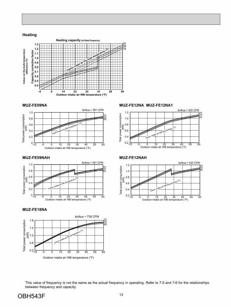
Heating
MUZ-FE18NA
This value of frequency is not the same as the actual frequency in operating. Refer to 7-5 and 7-6 for the relationships between frequency and capacity.
Indo
or a
ir D
ry-b
ulb
tem
pera
ture
diffe
renc
e (°
F)
Outdoor intake air WB temperature (°F) -4 5 14 23 32 41 50 59
0.40.50.60.70.80.91.01.11.21.3
Heating capacity (at Rated frequency)
Cap
acity
cor
rect
ion
fact
or
596879
Indoor intake air D
ry-bulb temperature ( F)
7075
-15 -5 5 15 25 35 45 55 650.2
0.6
1.0
1.4
1.8
Outdoor intake air WB temperature (°F)
Tota
l pow
er c
onsu
mpt
ion
(kW
)
= 738 CFMAirflow
Indoor intake air DB temperature (°F)
65
MUZ-FE09NA MUZ-FE12NA MUZ-FE12NA1
757065
-15 -5 5 15 25 35 45 55 650
0.2
0.4
0.6
0.8
1.0
Indoor intake air DB temperature (°F)
= 381 CFMAirflow
Outdoor intake air WB temperature (°F)
Tota
l pow
er c
onsu
mpt
ion
(kW
)
757065
-15 -5 5 15 25 35 45 55 650.2
0.4
0.6
0.8
1.0
1.2
Indoor intake air DB temperature (°F)
= 420 CFMAirflow
Outdoor intake air WB temperature (°F)
Tota
l pow
er c
onsu
mpt
ion
(kW
)
MUZ-FE09NAH MUZ-FE12NAH
OBH543F
14
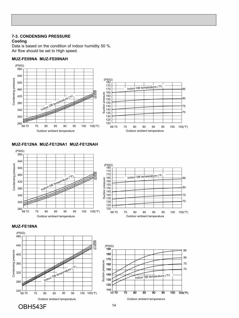
7-3. CONDENSING PRESSURECoolingData is based on the condition of indoor humidity 50 %.Air flow should be set to High speed.
MUZ-FE12NA MUZ-FE12NA1 MUZ-FE12NAH(PSIG)
Con
dens
ing
pres
sure
86807570
68 70 75 80 85 90 95 100 105(°F)120125130135140145150155160165170175180
Suc
tion
pres
sure
Outdoor ambient temperature
Indoor DB temperature (°F)
(PSIG)
86
80
75
70
68 70 75 80 85 90 95 100 105(°F)260
300
340
380
420
460
500
540
580
Indoor DB temperature (°F)
Outdoor ambient temperature
MUZ-FE09NA MUZ-FE09NAH(PSIG)
Con
dens
ing
pres
sure
86807570
68 70 75 80 85 90 95 100 105(°F)120125130135140145150155160165170175180
Suc
tion
pres
sure
Outdoor ambient temperature
Indoor DB temperature (°F)
(PSIG)
86
80
75
70
68 70 75 80 85 90 95 100 105(°F)260
300
340
380
420
460
500
540
580
Indoor DB temperature (°F)
Outdoor ambient temperature
MUZ-FE18NA(PSIG)
Con
dens
ing
pres
sure
86807570
70 75 80 85 90 95 100 105(°F)110
120
130
140
150
160
170
180
190
Suc
tion
pres
sure
Outdoor ambient temperature
Indoor DB temperature (°F)
(PSIG)86
80
75
70
68 70 75 80 85 90 95 100 105(°F)240
280
320
360
400
440
480
Indoor DB temperature (°F)
Outdoor ambient temperature
68 70 75 80 85 90 95 100 105(°F)110
120
130
140
150
160
170
180
190
OBH543F
15
75 7065
(PSIG) (PSIG)
Con
dens
ing
pres
sure
Outdoor ambient temperature
155 10 20 25 30 35 40 45 50 55 60 6570(°F)
220200180160140
240260280
320300
340360380400 75
7065
Suc
tion
pres
sure
Outdoor ambient temperature
15 205 10 25 30 35 40 45 50 55 60 6570(°F)
807060
50
90100110120130140150160170
-10-15 -10-1540120
Indoor DB temperature (°F)
Indoor DB te
mperature (°F)
58Hz58Hz
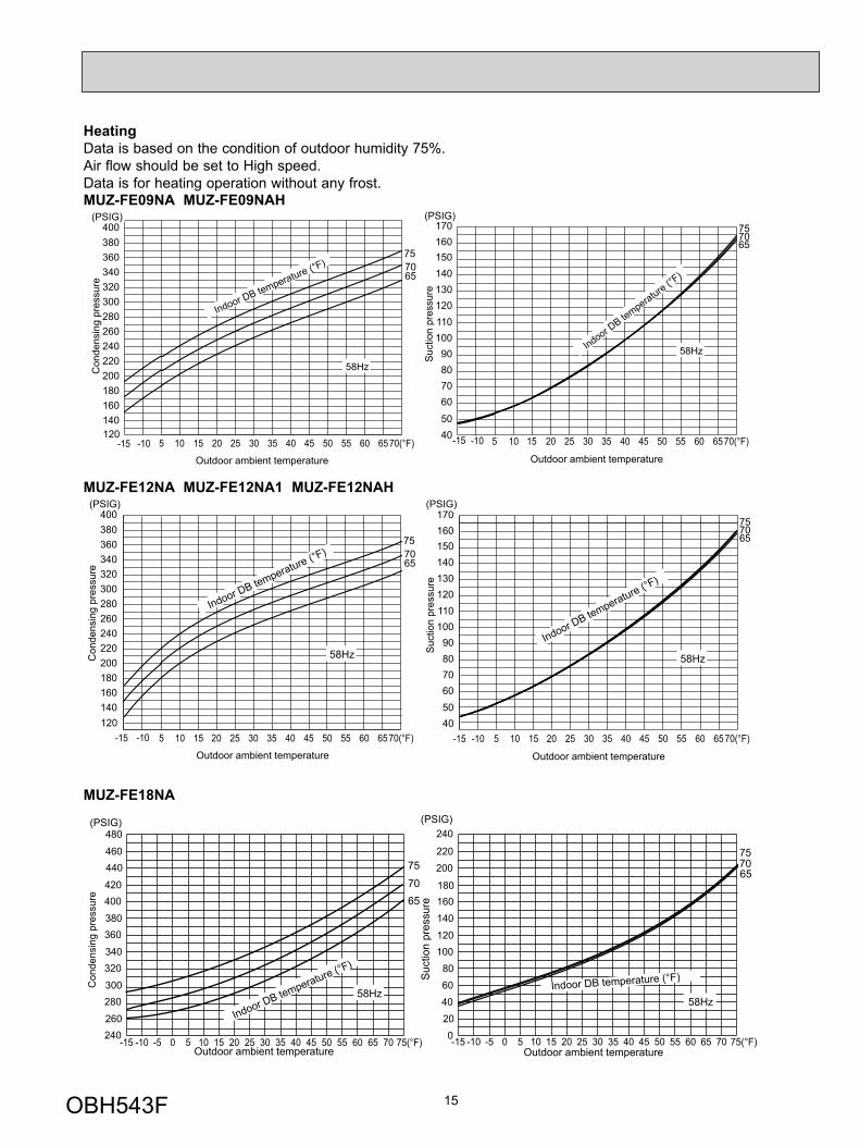
HeatingData is based on the condition of outdoor humidity 75%.Air flow should be set to High speed.Data is for heating operation without any frost.
75 7065
(PSIG) (PSIG)
Con
dens
ing
pres
sure
Outdoor ambient temperature
20 25 305 10 15 35 40 45 50 55 60 6570(°F)
220200180160140
240260280
320300
340360380400
757065
Suc
tion
pres
sure
Outdoor ambient temperature
20 25 305 10 15 35 40 45 50 55 60 6570(°F)
80706050
90100110120130140150160170
120-10-15 -15 -10
40
Indoor DB temperature (°F)
Indoor DB temperature (°F)
58Hz 58Hz
MUZ-FE18NA
(PSIG)
Con
dens
ing
pres
sure
75
7065
757065
Suc
tion
pres
sure
Outdoor ambient temperature
(PSIG)
-15 -10 -5 0 5 10 15 20 25 30 35 40 45 50 55 60 65 70 75(°F)240260
280300
320340
360380
400420
440460
480
-15 -10 -5 0 5 10 15 20 25 30 35 40 45 50 55 60 65 70 75(°F)020406080
100120
140160180
200220
240
Indoor DB temperature (°F)
Outdoor ambient temperature
Indoor DB temperature (°F)58Hz
58Hz
MUZ-FE09NA MUZ-FE09NAH
MUZ-FE12NA MUZ-FE12NA1 MUZ-FE12NAH
OBH543F
16
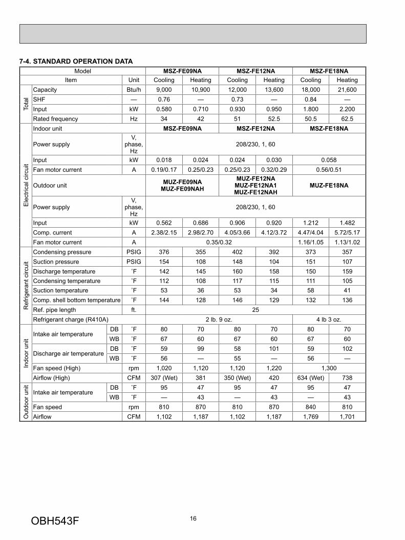
7-4. STANDARD OPERATION DATAModel MSZ-FE09NA MSZ-FE12NA MSZ-FE18NA
Item Unit Cooling Heating Cooling Heating Cooling Heating
Tota
l
Capacity Btu/h 9,000 10,900 12,000 13,600 18,000 21,600SHF — 0.76 — 0.73 — 0.84 —Input kW 0.580 0.710 0.930 0.950 1.800 2.200Rated frequency Hz 34 42 51 52.5 50.5 62.5
Ele
ctric
al c
ircui
t
Indoor unit MSZ-FE09NA MSZ-FE12NA MSZ-FE18NA
Power supplyV,
phase, Hz
208/230, 1, 60
Input kW 0.018 0.024 0.024 0.030 0.058Fan motor current A 0.19/0.17 0.25/0.23 0.25/0.23 0.32/0.29 0.56/0.51
Outdoor unit MUZ-FE09NAMUZ-FE09NAH
MUZ-FE12NAMUZ-FE12NA1MUZ-FE12NAH
MUZ-FE18NA
Power supplyV,
phase, Hz
208/230, 1, 60
Input kW 0.562 0.686 0.906 0.920 1.212 1.482Comp. current A 2.38/2.15 2.98/2.70 4.05/3.66 4.12/3.72 4.47/4.04 5.72/5.17Fan motor current A 0.35/0.32 1.16/1.05 1.13/1.02
Ref
riger
ant c
ircui
t
Condensing pressure PSIG 376 355 402 392 373 357Suction pressure PSIG 154 108 148 104 151 107Discharge temperature ˚F 142 145 160 158 150 159Condensing temperature ˚F 112 108 117 115 111 105Suction temperature ˚F 53 36 53 34 58 41Comp. shell bottom temperature ˚F 144 128 146 129 132 136Ref. pipe length ft. 25Refrigerant charge (R410A) 2 lb. 9 oz. 4 lb 3 oz.
Indo
or u
nit
Intake air temperatureDB ˚F 80 70 80 70 80 70WB ˚F 67 60 67 60 67 60
Discharge air temperatureDB ˚F 59 99 58 101 59 102WB ˚F 56 — 55 — 56 —
Fan speed (High) rpm 1,020 1,120 1,120 1,220 1,300Airfl ow (High) CFM 307 (Wet) 381 350 (Wet) 420 634 (Wet) 738
Out
door
uni
t
Intake air temperatureDB ˚F 95 47 95 47 95 47WB ˚F — 43 — 43 — 43
Fan speed rpm 810 870 810 870 840 810Airfl ow CFM 1,102 1,187 1,102 1,187 1,769 1,701
OBH543F
17
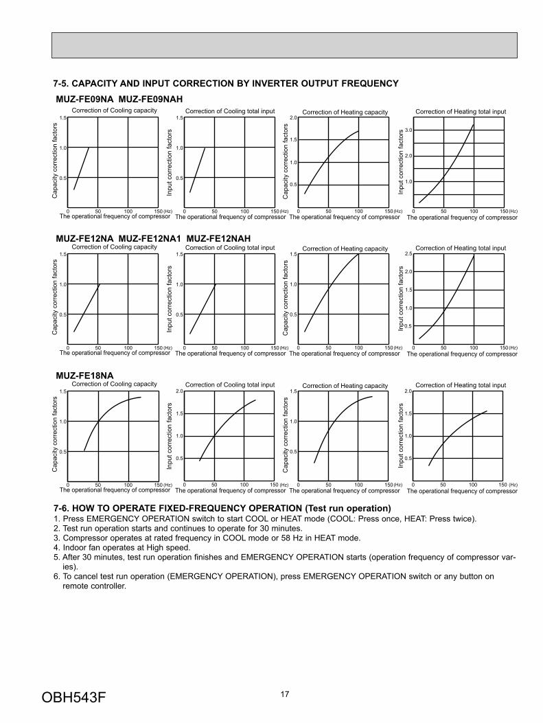
7-5. CAPACITY AND INPUT CORRECTION BY INVERTER OUTPUT FREQUENCY
Cap
acity
cor
rect
ion
fact
ors
Inpu
t cor
rect
ion
fact
ors
Inpu
t cor
rect
ion
fact
ors
Cap
acity
cor
rect
ion
fact
ors
Correction of Cooling capacity
The operational frequency of compressor
Correction of Cooling total input
The operational frequency of compressor
Correction of Heating total input
The operational frequency of compressor
Correction of Heating capacity
The operational frequency of compressor
MUZ-FE09NA MUZ-FE09NAH
0 50 100 150
0.5
1.0
1.5
(Hz) 0 50 100 150
0.5
1.0
1.5
(Hz) 0 50 100 150
0.5
1.0
2.0
1.5
(Hz) 0 50 100 150
1.0
2.0
3.0
(Hz)
MUZ-FE12NA MUZ-FE12NA1 MUZ-FE12NAH
Cap
acity
cor
rect
ion
fact
ors
Inpu
t cor
rect
ion
fact
ors
Inpu
t cor
rect
ion
fact
ors
Cap
acity
cor
rect
ion
fact
ors
Correction of Cooling capacity
The operational frequency of compressor
Correction of Cooling total input
The operational frequency of compressor
Correction of Heating total input
The operational frequency of compressor
Correction of Heating capacity
The operational frequency of compressor0 50 100 150
0.5
1.0
1.5
(Hz) 0 50 100 150
0.5
1.0
1.5
(Hz) 0 50 100 150
0.5
1.0
1.5
(Hz) 0 50 100 150
1.0
0.5
1.5
2.0
2.5
(Hz)
MUZ-FE18NA
Cap
acity
cor
rect
ion
fact
ors
Inpu
t cor
rect
ion
fact
ors
Inpu
t cor
rect
ion
fact
ors
Cap
acity
cor
rect
ion
fact
ors
Correction of Cooling capacity
The operational frequency of compressor
Correction of Cooling total input
The operational frequency of compressor
Correction of Heating total input
The operational frequency of compressor
Correction of Heating capacity
The operational frequency of compressor0 50 100 150
0.5
1.0
1.5
(Hz) (Hz) 0 50 100 150
0.5
1.0
1.5
(Hz) (Hz)0 50 100 150
0.5
1.0
1.5
2.0
0 50 100 150
0.5
1.0
1.5
2.0
7-6. HOW TO OPERATE FIXED-FREQUENCY OPERATION (Test run operation)1. Press EMERGENCY OPERATION switch to start COOL or HEAT mode (COOL: Press once, HEAT: Press twice).2. Test run operation starts and continues to operate for 30 minutes.3. Compressor operates at rated frequency in COOL mode or 58 Hz in HEAT mode.4. Indoor fan operates at High speed.5. After 30 minutes, test run operation finishes and EMERGENCY OPERATION starts (operation frequency of compressor var-
ies).6. To cancel test run operation (EMERGENCY OPERATION), press EMERGENCY OPERATION switch or any button on
remote controller.
OBH543F
18
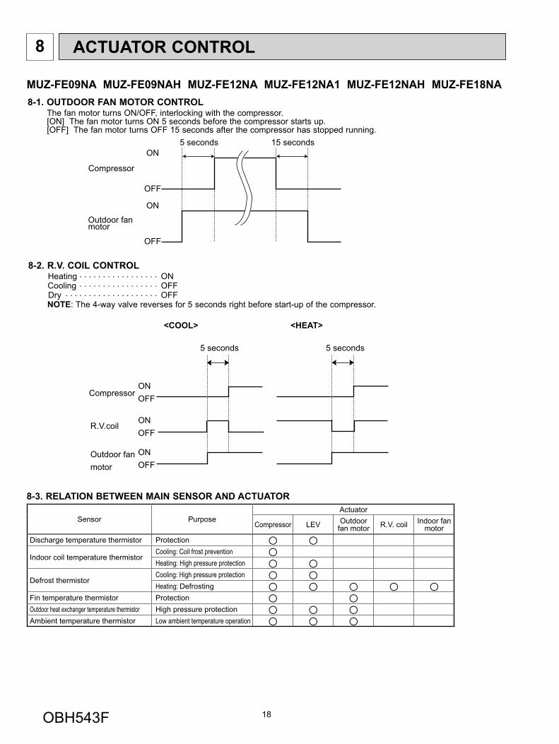
8 ACTUATOR CONTROL
MUZ-FE09NA MUZ-FE09NAH MUZ-FE12NA MUZ-FE12NA1 MUZ-FE12NAH MUZ-FE18NA
8-2. R.V. COIL CONTROLHeating . . . . . . . . . . . . . . . . . ON Cooling . . . . . . . . . . . . . . . . . OFFDry . . . . . . . . . . . . . . . . . . . . OFFNOTE: The 4-way valve reverses for 5 seconds right before start-up of the compressor.
ON
OFF
ON
OFF
Outdoor fanmotor
Compressor
5 seconds 15 seconds
8-1. OUTDOOR FAN MOTOR CONTROLThe fan motor turns ON/OFF, interlocking with the compressor.[ON] The fan motor turns ON 5 seconds before the compressor starts up.[OFF] The fan motor turns OFF 15 seconds after the compressor has stopped running.
8-3. RELATION BETWEEN MAIN SENSOR AND ACTUATOR
Sensor Purpose Actuator
Compressor LEV Outdoor fan motor R.V. coil Indoor fan
motor Discharge temperature thermistor Protection ○ ○Indoor coil temperature thermistor
Cooling: Coil frost prevention ○Heating: High pressure protection ○ ○
Defrost thermistor Cooling: High pressure protection ○ ○Heating: Defrosting ○ ○ ○ ○ ○
Fin temperature thermistor Protection ○ ○Outdoor heat exchanger temperature thermistor High pressure protection ○ ○ ○Ambient temperature thermistor Low ambient temperature operation ○ ○ ○
ONOFF
Compressor
Outdoor fanmotor
R.V.coilONOFF
ONOFF
<COOL>
5 seconds
<HEAT>
5 seconds
OBH543F
19
SERVICE FUNCTIONS9
9-1. CHANGE IN DEFROST SETTINGChanging defrost finish temperature<JS> To change the defrost finish temperature, cut/solder the JS wire of the outdoor inverter P.C. board (Refer to 10-6.1.).
JumperDefrost fi nish temperature
MUZ-FE09/12NAMUZ-FE12NA1
MUZ-FE09/12NAHMUZ-FE18NA
JS
Soldered(Initial setting) 41°F (5°C) 50°F (10°C)
None(Cut) 50°F (10°C) 64°F (18°C)
MUZ-FE09NA MUZ-FE09NAH MUZ-FE12NA MUZ-FE12NA1 MUZ-FE12NAH MUZ-FE18NA
9-2. PRE-HEAT CONTROL SETTINGPRE-HEAT CONTROLWhen moisture gets into the refrigerant cycle, it may interfere the start-up of the compressor at low outside temperature. The pre-heat control prevents this interference. The pre-heat control turns ON when outside temperature is 68°F (20°C) or below. When pre-heat control is turned ON, compressor is energized. (About 50 W)
<JK> To activate the pre-heat control, cut the JK wire of the inverter P.C. board (Refer to 10-6.1.).
NOTE: When the inverter P.C. board is replaced, check the Jumper wires, and cut/solder them if necessary.
10 TROUBLESHOOTING
10-1. CAUTIONS ON TROUBLESHOOTING1. Before troubleshooting, check the following
1) Check the power supply voltage.2) Check the indoor/outdoor connecting wire for miswiring.
2. Take care of the following during servicing1) Before servicing the air conditioner, be sure to turn OFF the main unit first with the remote controller, then after con-
firming the horizontal vane is closed, turn off the breaker and/or disconnect the power plug.2) Be sure to turn OFF the power supply before removing the front panel, the cabinet, the top panel, and the electronic
control P.C. board.3) When removing the electrical parts, be careful of the residual voltage of smoothing capacitor. 4) When removing the electronic control P.C. board, hold the edge of the board with care NOT to apply stress on the
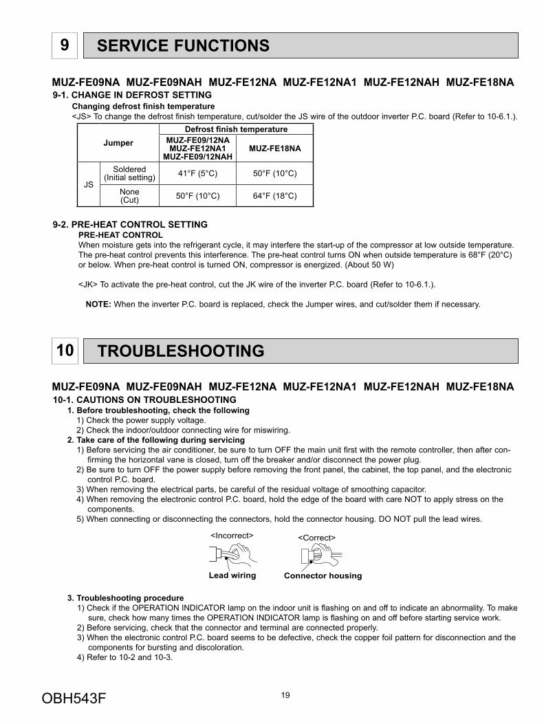
components.5) When connecting or disconnecting the connectors, hold the connector housing. DO NOT pull the lead wires.
3. Troubleshooting procedure1) Check if the OPERATION INDICATOR lamp on the indoor unit is flashing on and off to indicate an abnormality. To make
sure, check how many times the OPERATION INDICATOR lamp is flashing on and off before starting service work.2) Before servicing, check that the connector and terminal are connected properly.3) When the electronic control P.C. board seems to be defective, check the copper foil pattern for disconnection and the
components for bursting and discoloration.4) Refer to 10-2 and 10-3.
Lead wiring
<Incorrect>
Connector housing
<Correct>
MUZ-FE09NA MUZ-FE09NAH MUZ-FE12NA MUZ-FE12NA1 MUZ-FE12NAH MUZ-FE18NA
OBH543F
20
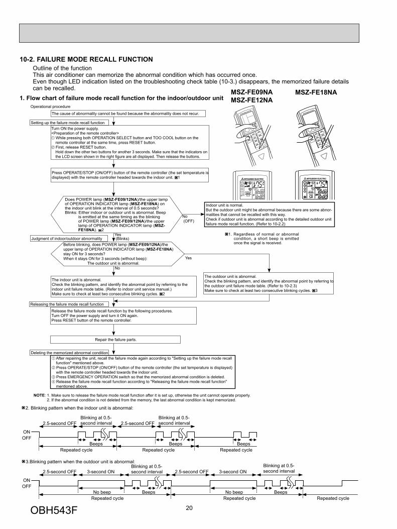
10-2. FAILURE MODE RECALL FUNCTION
1. Flow chart of failure mode recall function for the indoor/outdoor unitMSZ-FE09NAMSZ-FE12NA
MSZ-FE18NA
Outline of the functionThis air conditioner can memorize the abnormal condition which has occurred once.Even though LED indication listed on the troubleshooting check table (10-3.) disappears, the memorized failure details can be recalled.
2. Blinking pattern when the indoor unit is abnormal:
3.Blinking pattern when the outdoor unit is abnormal:
ONOFF
BeepsRepeated cycle Repeated cycle
ONOFF
No beep BeepsRepeated cycle
2.5-second OFFBlinking at 0.5-second interval
2.5-second OFF 3-second ONBlinking at 0.5-second interval
BeepsRepeated cycle
2.5-second OFFBlinking at 0.5-second interval
No beep BeepsRepeated cycle
2.5-second OFF 3-second ONBlinking at 0.5-second interval
Repeated cycle
Beeps
Does POWER lamp (MSZ-FE09/12NA)/the upper lamp of OPERATION INDICATOR lamp (MSZ-FE18NA) on the indoor unit blink at the interval of 0.5 seconds?Blinks: Either indoor or outdoor unit is abnormal. Beep
is emitted at the same timing as the blinking of POWER lamp (MSZ-FE09/12NA)/the upper lamp of OPERATION INDICATOR lamp (MSZ-FE18NA). 2
Indoor unit is normal.But the outdoor unit might be abnormal because there are some abnor-malities that cannot be recalled with this way.Check if outdoor unit is abnormal according to the detailed outdoor unit failure mode recall function. (Refer to 10-2.2)
No
Yes
The cause of abnormality cannot be found because the abnormality does not recur.
Setting up the failure mode recall functionTurn ON the power supply.<Preparation of the remote controller>
While pressing both OPERATION SELECT button and TOO COOL button on the remote controller at the same time, press RESET button. First, release RESET button.
Hold down the other two buttons for another 3 seconds. Make sure that the indicators on the LCD screen shown in the right fi gure are all displayed. Then release the buttons.
Press OPERATE/STOP (ON/OFF) button of the remote controller (the set temperature is displayed) with the remote controller headed towards the indoor unit. 1
Judgment of indoor/outdoor abnormalityBefore blinking, does POWER lamp (MSZ-FE09/12NA)/the upper lamp of OPERATION INDICATOR lamp (MSZ-FE18NA) stay ON for 3 seconds?When it stays ON for 3 seconds (without beep):
The outdoor unit is abnormal.
The indoor unit is abnormal.Check the blinking pattern, and identify the abnormal point by referring to the indoor unit failure mode table. (Refer to indoor unit service manual.)Make sure to check at least two consecutive blinking cycles. 2
Releasing the failure mode recall functionRelease the failure mode recall function by the following procedures.Turn OFF the power supply and turn it ON again.Press RESET button of the remote controller.
The outdoor unit is abnormal.Check the blinking pattern, and identify the abnormal point by referring to the outdoor unit failure mode table. (Refer to 10-2.3)Make sure to check at least two consecutive blinking cycles. 3
Repair the failure parts.
Deleting the memorized abnormal condition After repairing the unit, recall the failure mode again according to "Setting up the failure mode recall function" mentioned above. Press OPERATE/STOP (ON/OFF) button of the remote controller (the set temperature is displayed) with the remote controller headed towards the indoor unit. Press EMERGENCY OPERATION switch so that the memorized abnormal condition is deleted. Release the failure mode recall function according to "Releasing the failure mode recall function" mentioned above.
Operational procedure
Yes (Blinks)
No (OFF)
NOTE: 1. Make sure to release the failure mode recall function after it is set up, otherwise the unit cannot operate properly. 2. If the abnormal condition is not deleted from the memory, the last abnormal condition is kept memorized.
1. Regardless of normal or abnormal condition, a short beep is emitted once the signal is received.
OBH543F
21
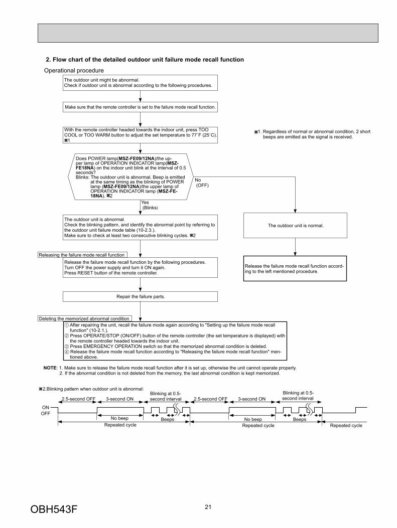
Does POWER lamp(MSZ-FE09/12NA)/the up-per lamp of OPERATION INDICATOR lamp(MSZ-FE18NA) on the indoor unit blink at the interval of 0.5 seconds?Blinks: The outdoor unit is abnormal. Beep is emitted
at the same timing as the blinking of POWER lamp (MSZ-FE09/12NA)/the upper lamp of OPERATION INDICATOR lamp (MSZ-FE-18NA). 2
Yes (Blinks)
No (OFF)
The outdoor unit might be abnormal.Check if outdoor unit is abnormal according to the following procedures.
Operational procedure
Make sure that the remote controller is set to the failure mode recall function.
With the remote controller headed towards the indoor unit, press TOO COOL or TOO WARM button to adjust the set temperature to 77˚F (25˚C).
1
1. Regardless of normal or abnormal condition, 2 short beeps are emitted as the signal is received.
The outdoor unit is abnormal.Check the blinking pattern, and identify the abnormal point by referring to the outdoor unit failure mode table (10-2.3.). Make sure to check at least two consecutive blinking cycles. 2
Releasing the failure mode recall functionRelease the failure mode recall function by the following procedures.Turn OFF the power supply and turn it ON again.Press RESET button of the remote controller.
Repair the failure parts.
The outdoor unit is normal.
Release the failure mode recall function accord-ing to the left mentioned procedure.
Deleting the memorized abnormal condition After repairing the unit, recall the failure mode again according to "Setting up the failure mode recall function" (10-2.1.). Press OPERATE/STOP (ON/OFF) button of the remote controller (the set temperature is displayed) with the remote controller headed towards the indoor unit. Press EMERGENCY OPERATION switch so that the memorized abnormal condition is deleted. Release the failure mode recall function according to "Releasing the failure mode recall function" men-tioned above.
NOTE: 1. Make sure to release the failure mode recall function after it is set up, otherwise the unit cannot operate properly. 2. If the abnormal condition is not deleted from the memory, the last abnormal condition is kept memorized.
2. Flow chart of the detailed outdoor unit failure mode recall function
2.Blinking pattern when outdoor unit is abnormal:
ONOFF
No beep BeepsRepeated cycle
2.5-second OFF 3-second ONBlinking at 0.5-second interval
No beep BeepsRepeated cycle
2.5-second OFF 3-second ONBlinking at 0.5-second interval
Repeated cycle
OBH543F
22
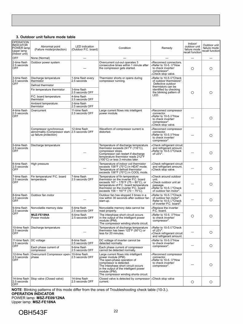
3. Outdoor unit failure mode tableOPERATION INDICATOR POWER lampUpper lamp(Indoor unit)
Abnormal point (Failure mode/protection)
LED indication(Outdoor P.C. board) Condition Remedy
Indoor/outdoor unit failure mode
recall function
Outdoor unit failure mode
recall function
OFF None (Normal) — — — — —2-time fl ash 2.5 seconds OFF
Outdoor power system
—
Overcurrent cut-out operates 3 consecutive times within 1 minute after the compressor gets started.
• Reconnect connectors.• Refer to 10-5. "How to check inverter/compressor".
• Check stop valve. ○ ○
3-time fl ash2.5 seconds OFF
Discharge temperature thermistor
1-time fl ash every 2.5 seconds
Thermistor shorts or opens during compressor running.
• Refer to 10-5. "Check of outdoor thermistors". Defective outdoor thermistors can be identifi ed by checking the blinking pattern of LED. ○ ○
Defrost thermistor Fin temperature thermistor 3-time fl ash
2.5 seconds OFF P.C. board temperature thermistor
4-time fl ash2.5 seconds OFF
Ambient temperature thermistor
2-time fl ash 2.5 seconds OFF
4-time fl ash 2.5 seconds OFF
Overcurrent 11-time fl ash 2.5 seconds OFF
Large current fl ows into intelligent power module.
• Reconnect compressor connector.
• Refer to 10-5. "How to check inverter/compressor".
• Check stop valve.
— ○Compressor synchronous abnormality (Compressor start-up failure protection)
12-time fl ash 2.5 seconds OFF
Waveform of compressor current is distorted.
• Reconnect compressor connector.
• Refer to 10-5. "How to check inverter/compressor".
— ○5-time fl ash 2.5 seconds OFF
Discharge temperature
—
Temperature of discharge temperature thermistor exceeds 241°F (116°C), compressor stops. Compressor can restart if discharge temperature thermistor reads 212°F (100°C) or less 3 minutes later.
• Check refrigerant circuit and refrigerant amount.
• Refer to 10-5. "Check of LEV". — ○
6-time fl ash 2.5 seconds OFF
High pressure —
Temperature of indoor coil thermistor exceeds 158°F (70°C) in HEAT mode. Temperature of defrost thermistor exceeds 158°F (70°C) in COOL mode.
• Check refrigerant circuit and refrigerant amount.
• Check stop valve. — ○7-time fl ash 2.5 seconds OFF
Fin temperature/ P.C. board temperature
7-time fl ash 2.5 seconds OFF
Temperature of fi n temperature thermistor on the inverter P.C. board exceeds 167 ~ 176°F (75 ~ 80°C), or temperature of P.C. board temperature thermistor on the inverter P.C. board exceeds 158 ~ 167°F (70 ~ 75°C).
• Check around outdoor unit.
• Check outdoor unit air passage.
• Refer to 10-5. "Check of outdoor fan motor".
— ○8-time fl ash 2.5 seconds OFF
Outdoor fan motor —
Outdoor fan has stopped 3 times in a row within 30 seconds after outdoor fan start-up.
• Refer to 10-5. "Check of outdoor fan motor". Refer to 10-5. "Check of inverter P.C. board".
— ○9-time fl ash 2.5 seconds OFF
Nonvolatile memory data 5-time fl ash 2.5 seconds OFF
Nonvolatile memory data cannot be read properly.
• Replace the inverter P.C. board.
○ ○MUZ-FE18NAPower module
6-time fl ash2.5 seconds OFF
The interphase short circuit occurs in the output of the intelligent power module (IPM). The compressor winding shorts circuit.
• Refer to 10-5. "How to check inverter/compressor".
10-time fl ash 2.5 seconds OFF
Discharge temperature —
Temperature of discharge temperature thermistor has been 122°F (50°C) or less for 20 minutes.
• Refer to 10-5. "Check of LEV".
• Check refrigerant circuit and refrigerant amount.
— ○11-time fl ash 2.5 seconds OFF
DC voltage 8-time fl ash 2.5 seconds OFF
DC voltage of inverter cannot be detected normally.
• Refer to 10-5. "How to check inverter/compressor". — ○Each phase current of
compressor 9-time fl ash 2.5 seconds OFF
Each phase current of compressor cannot be detected normally.
12-time fl ash 2.5 seconds OFF
Overcurrent Compressor open-phase
10-time fl ash 2.5 seconds OFF
Large current fl ows into intelligent power module (IPM). The open-phase operation of compressor is detected. The interphase short circuit occurs in the output of the intelligent power module (IPM). The compressor winding shorts circuit.
• Reconnect compressor connector.
• Refer to 10-5. "How to check inverter/compressor". — ○
14-time fl ash 2.5 seconds OFF
Stop valve (Closed valve) 14-time fl ash 2.5 seconds OFF
Closed valve is detected by compressor current.
• Check stop valve ○ ○
NOTE: Blinking patterns of this mode differ from the ones of Troubleshooting check table (10-3.).OPERATION INDICATORPOWER lamp: MSZ-FE09/12NAUpper lamp: MSZ-FE18NA
OBH543F
23
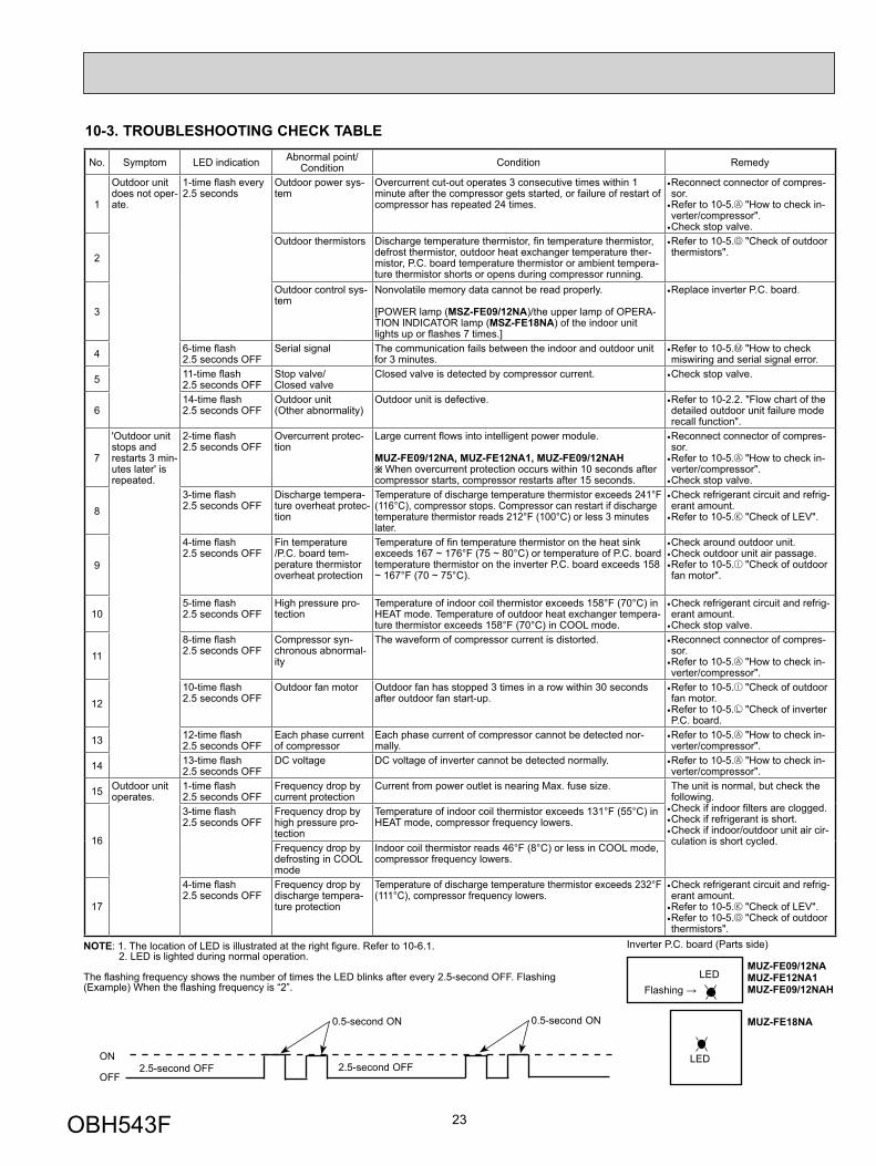
10-3. TROUBLESHOOTING CHECK TABLE
No. Symptom LED indication Abnormal point/ Condition Condition Remedy
1
Outdoor unit does not oper-ate.
1-time fl ash every 2.5 seconds
Outdoor power sys-tem
Overcurrent cut-out operates 3 consecutive times within 1 minute after the compressor gets started, or failure of restart of compressor has repeated 24 times.
• Reconnect connector of compres-sor.
• Refer to 10-5. "How to check in-verter/compressor".
• Check stop valve.
2Outdoor thermistors Discharge temperature thermistor, fi n temperature thermistor,
defrost thermistor, outdoor heat exchanger temperature ther-mistor, P.C. board temperature thermistor or ambient tempera-ture thermistor shorts or opens during compressor running.
• Refer to 10-5. "Check of outdoor thermistors".
3
Outdoor control sys-tem
Nonvolatile memory data cannot be read properly.
[POWER lamp (MSZ-FE09/12NA)/the upper lamp of OPERA-TION INDICATOR lamp (MSZ-FE18NA) of the indoor unit lights up or fl ashes 7 times.]
• Replace inverter P.C. board.
4 6-time fl ash 2.5 seconds OFF
Serial signal The communication fails between the indoor and outdoor unit for 3 minutes.
• Refer to 10-5. "How to check miswiring and serial signal error.
5 11-time fl ash 2.5 seconds OFF
Stop valve/ Closed valve
Closed valve is detected by compressor current. • Check stop valve.
614-time fl ash 2.5 seconds OFF
Outdoor unit(Other abnormality)
Outdoor unit is defective. • Refer to 10-2.2. "Flow chart of the detailed outdoor unit failure mode recall function".
7
'Outdoor unit stops and restarts 3 min-utes later' is repeated.
2-time fl ash 2.5 seconds OFF
Overcurrent protec-tion
Large current fl ows into intelligent power module.
MUZ-FE09/12NA, MUZ-FE12NA1, MUZ-FE09/12NAH When overcurrent protection occurs within 10 seconds after
compressor starts, compressor restarts after 15 seconds.
• Reconnect connector of compres-sor.
• Refer to 10-5. "How to check in-verter/compressor".
• Check stop valve.
83-time fl ash 2.5 seconds OFF
Discharge tempera-ture overheat protec-tion
Temperature of discharge temperature thermistor exceeds 241°F (116°C), compressor stops. Compressor can restart if discharge temperature thermistor reads 212°F (100°C) or less 3 minutes later.
• Check refrigerant circuit and refrig-erant amount.
• Refer to 10-5. "Check of LEV".
9
4-time fl ash 2.5 seconds OFF
Fin temperature /P.C. board tem-perature thermistor overheat protection
Temperature of fi n temperature thermistor on the heat sink exceeds 167 ~ 176°F (75 ~ 80°C) or temperature of P.C. board temperature thermistor on the inverter P.C. board exceeds 158 ~ 167°F (70 ~ 75°C).
• Check around outdoor unit.• Check outdoor unit air passage.• Refer to 10-5. "Check of outdoor fan motor".
105-time fl ash 2.5 seconds OFF
High pressure pro-tection
Temperature of indoor coil thermistor exceeds 158°F (70°C) in HEAT mode. Temperature of outdoor heat exchanger tempera-ture thermistor exceeds 158°F (70°C) in COOL mode.
• Check refrigerant circuit and refrig-erant amount.
• Check stop valve.
118-time fl ash 2.5 seconds OFF
Compressor syn-chronous abnormal-ity
The waveform of compressor current is distorted. • Reconnect connector of compres-sor.
• Refer to 10-5. "How to check in-verter/compressor".
1210-time fl ash 2.5 seconds OFF
Outdoor fan motor Outdoor fan has stopped 3 times in a row within 30 seconds after outdoor fan start-up.
• Refer to 10-5. "Check of outdoor fan motor.
• Refer to 10-5. "Check of inverter P.C. board.
13 12-time fl ash 2.5 seconds OFF
Each phase current of compressor
Each phase current of compressor cannot be detected nor-mally.
• Refer to 10-5. "How to check in-verter/compressor".
14 13-time fl ash 2.5 seconds OFF
DC voltage DC voltage of inverter cannot be detected normally. • Refer to 10-5. "How to check in-verter/compressor".
15 Outdoor unit operates.
1-time fl ash 2.5 seconds OFF
Frequency drop by current protection
Current from power outlet is nearing Max. fuse size. The unit is normal, but check the following.
• Check if indoor fi lters are clogged.• Check if refrigerant is short.• Check if indoor/outdoor unit air cir-culation is short cycled. 16
3-time fl ash 2.5 seconds OFF
Frequency drop by high pressure pro-tection
Temperature of indoor coil thermistor exceeds 131°F (55°C) in HEAT mode, compressor frequency lowers.
Frequency drop by defrosting in COOL mode
Indoor coil thermistor reads 46°F (8°C) or less in COOL mode, compressor frequency lowers.
17
4-time fl ash 2.5 seconds OFF
Frequency drop by discharge tempera-ture protection
Temperature of discharge temperature thermistor exceeds 232°F (111°C), compressor frequency lowers.
• Check refrigerant circuit and refrig-erant amount.
• Refer to 10-5. "Check of LEV".• Refer to 10-5. "Check of outdoor thermistors".
NOTE: 1. The location of LED is illustrated at the right fi gure. Refer to 10-6.1. 2. LED is lighted during normal operation.
The fl ashing frequency shows the number of times the LED blinks after every 2.5-second OFF. Flashing (Example) When the fl ashing frequency is “2”.
ON
OFF2.5-second OFF 2.5-second OFF
0.5-second ON 0.5-second ON
LEDFlashing →
Inverter P.C. board (Parts side)
LED
MUZ-FE09/12NAMUZ-FE12NA1MUZ-FE09/12NAH
MUZ-FE18NA
OBH543F
24
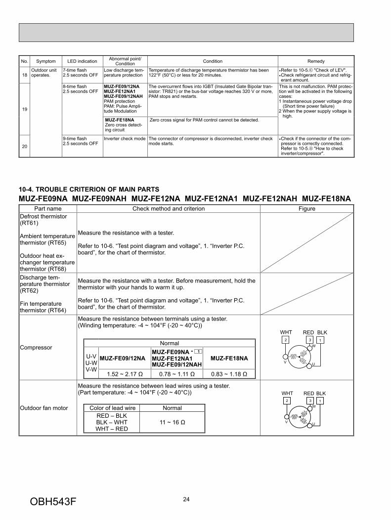
No. Symptom LED indication Abnormal point/ Condition Condition Remedy
18Outdoor unit operates.
7-time fl ash 2.5 seconds OFF
Low discharge tem-perature protection
Temperature of discharge temperature thermistor has been 122°F (50°C) or less for 20 minutes.
• Refer to 10-5. "Check of LEV".• Check refrigerant circuit and refrig-erant amount.
19
8-time fl ash 2.5 seconds OFF
MUZ-FE09/12NAMUZ-FE12NA1MUZ-FE09/12NAHPAM protection PAM: Pulse Ampli-tude Modulation
The overcurrent fl ows into IGBT (Insulated Gate Bipolar tran-sistor: TR821) or the bus-bar voltage reaches 320 V or more, PAM stops and restarts.
This is not malfunction. PAM protec-tion will be activated in the following cases:1 Instantaneous power voltage drop
(Short time power failure)2 When the power supply voltage is
high. MUZ-FE18NAZero cross detect-ing circuit
Zero cross signal for PAM control cannot be detected.
20
9-time fl ash 2.5 seconds OFF
Inverter check mode The connector of compressor is disconnected, inverter check mode starts.
• Check if the connector of the com-pressor is correctly connected. Refer to 10-5. "How to check inverter/compressor".
10-4. TROUBLE CRITERION OF MAIN PARTSMUZ-FE09NA MUZ-FE09NAH MUZ-FE12NA MUZ-FE12NA1 MUZ-FE12NAH MUZ-FE18NA
Part name Check method and criterion FigureDefrost thermistor (RT61)
Ambient temperature thermistor (RT65)
Outdoor heat ex-changer temperature thermistor (RT68)
Measure the resistance with a tester.
Refer to 10-6. “Test point diagram and voltage”, 1. “Inverter P.C. board”, for the chart of thermistor.
Discharge tem-perature thermistor (RT62)
Fin temperature thermistor (RT64)
Measure the resistance with a tester. Before measurement, hold the thermistor with your hands to warm it up.
Refer to 10-6. “Test point diagram and voltage”, 1. “Inverter P.C. board”, for the chart of thermistor.
Compressor
Measure the resistance between terminals using a tester. (Winding temperature: -4 ~ 104°F (-20 ~ 40°C))
Normal
U-VU-WV-W
MUZ-FE09/12NAMUZ-FE09NA - 1
MUZ-FE12NA1MUZ-FE09/12NAH
MUZ-FE18NA
1.52 ~ 2.17 Ω 0.78 ~ 1.11 Ω 0.83 ~ 1.18 Ω
2 3W
UV
1
WHT RED BLK
Outdoor fan motor
Measure the resistance between lead wires using a tester. (Part temperature: -4 ~ 104°F (-20 ~ 40°C))
Color of lead wire NormalRED – BLKBLK – WHTWHT – RED
11 ~ 16 Ω
2 3W
UV
1
WHT RED BLK
OBH543F
25
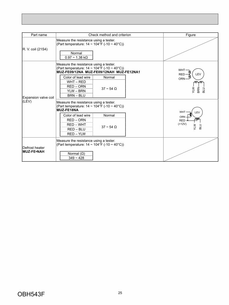
Part name Check method and criterion Figure
R. V. coil (21S4)
Measure the resistance using a tester. (Part temperature: 14 ~ 104°F (-10 ~ 40°C))
Normal0.97 ~ 1.38 kΩ
Expansion valve coil (LEV)
Measure the resistance using a tester. (Part temperature: 14 ~ 104°F (-10 ~ 40°C))MUZ-FE09/12NA MUZ-FE09/12NAH MUZ-FE12NA1
Color of lead wire NormalWHT – RED
37 ~ 54 ΩRED – ORNYLW – BRNBRN – BLU
LEVWHTREDORN
YLW
BR
N
BLU
Measure the resistance using a tester. (Part temperature: 14 ~ 104°F (-10 ~ 40°C))MUZ-FE18NA
Color of lead wire NormalRED – ORN
37 ~ 54 ΩRED – WHTRED – BLURED – YLW
RED(+12V)
YLW BLU
WHT
ORN
LEV
Defrost heaterMUZ-FE•NAH
Measure the resistance using a tester. (Part temperature: 14 ~ 104°F (-10 ~ 40°C))
Normal (Ω)349 ~ 428
OBH543F
26
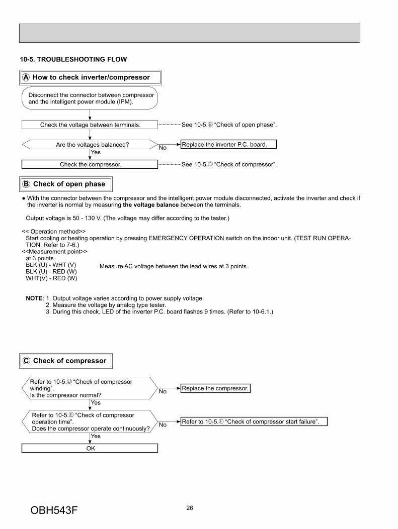
10-5. TROUBLESHOOTING FLOW
Are the voltages balanced?
Disconnect the connector between compressor and the intelligent power module (IPM).
Replace the inverter P.C. board.
Check the voltage between terminals.
Check the compressor. See 10-5. “Check of compressor”.
NoYes
See 10-5. “Check of open phase”.
● With the connector between the compressor and the intelligent power module disconnected, activate the inverter and check if the inverter is normal by measuring the voltage balance between the terminals.
Output voltage is 50 - 130 V. (The voltage may differ according to the tester.)
<< Operation method>> Start cooling or heating operation by pressing EMERGENCY OPERATION switch on the indoor unit. (TEST RUN OPERA-
TION: Refer to 7-6.)<<Measurement point>> at 3 points BLK (U) - WHT (V) BLK (U) - RED (W) WHT(V) - RED (W)
NOTE: 1. Output voltage varies according to power supply voltage. 2. Measure the voltage by analog type tester. 3. During this check, LED of the inverter P.C. board fl ashes 9 times. (Refer to 10-6.1.)
Measure AC voltage between the lead wires at 3 points.
Refer to 10-5. “Check of compressor operation time”.Does the compressor operate continuously?
Refer to 10-5. “Check of compressor start failure”.
OK
No
Yes
Refer to 10-5. “Check of compressor winding”.Is the compressor normal?
Replace the compressor.No
Yes
B Check of open phase
A How to check inverter/compressor
C Check of compressor
OBH543F
27
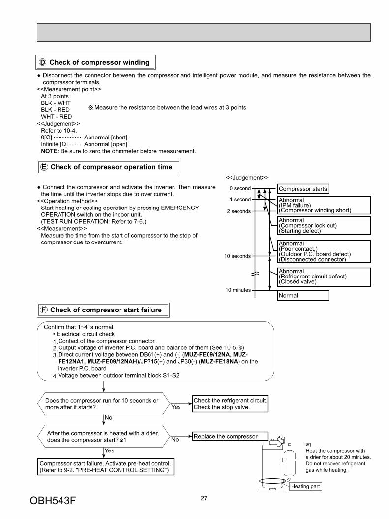
F Check of compressor start failure
D Check of compressor winding
E Check of compressor operation time
● Disconnect the connector between the compressor and intelligent power module, and measure the resistance between the compressor terminals.
<<Measurement point>> At 3 points BLK - WHT BLK - RED WHT - RED<<Judgement>> Refer to 10-4. 0[Ω] ················· Abnormal [short] Infinite [Ω] ········ Abnormal [open] NOTE: Be sure to zero the ohmmeter before measurement.
Measure the resistance between the lead wires at 3 points.
After the compressor is heated with a drier, does the compressor start? 1 Replace the compressor.
Compressor start failure. Activate pre-heat control.(Refer to 9-2. "PRE-HEAT CONTROL SETTING")
No
Yes
Does the compressor run for 10 seconds or more after it starts?
Check the refrigerant circuit.Check the stop valve.Yes
No
1Heat the compressor with a drier for about 20 minutes.Do not recover refrigerantgas while heating.
Heating part
● Connect the compressor and activate the inverter. Then measure the time until the inverter stops due to over current.
<<Operation method>> Start heating or cooling operation by pressing EMERGENCY
OPERATION switch on the indoor unit. (TEST RUN OPERATION: Refer to 7-6.)<<Measurement>> Measure the time from the start of compressor to the stop of
compressor due to overcurrent.
Compressor starts
Abnormal(IPM failure)(Compressor winding short)Abnormal(Compressor lock out)(Starting defect)
Abnormal(Poor contact,)(Outdoor P.C. board defect)(Disconnected connector)
Abnormal(Refrigerant circuit defect)(Closed valve)
Normal
0 second
1 second
2 seconds
10 seconds
10 minutes
<<Judgement>>
Confi rm that 1~4 is normal.• Electrical circuit check1. Contact of the compressor connector2. Output voltage of inverter P.C. board and balance of them (See 10-5. )3. Direct current voltage between DB61(+) and (-) (MUZ-FE09/12NA, MUZ- FE12NA1, MUZ-FE09/12NAH)/JP715(+) and JP30(-) (MUZ-FE18NA) on the inverter P.C. board4. Voltage between outdoor terminal block S1-S2
OBH543F
28
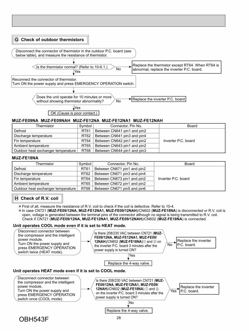
Is the thermistor normal? (Refer to 10-6.1.)
Reconnect the connector of thermistor.Turn ON the power supply and press EMERGENCY OPERATION switch.
NoReplace the thermistor except RT64. When RT64 is abnormal, replace the inverter P.C. board.
Does the unit operate for 10 minutes or more without showing thermistor abnormality?
OK (Cause is poor contact.)
Replace the inverter P.C. board.
Thermistor Symbol Connector, Pin No. Board Defrost RT61 Between CN641 pin1 and pin2
Inverter P.C. boardDischarge temperature RT62 Between CN641 pin3 and pin4 Fin temperature RT64 Between CN642 pin1 and pin2 Ambient temperature RT65 Between CN643 pin1 and pin2 Outdoor heat exchanger temperature RT68 Between CN644 pin1 and pin3
Yes
Yes
No
G Check of outdoor thermistors
H Check of R.V. coil
First of all, measure the resistance of R.V. coil to check if the coil is defective. Refer to 10-4. In case CN721 (MUZ-FE09/12NA, MUZ-FE12NA1, MUZ-FE09/12NAH)/CN602 (MUZ-FE18NA) is disconnected or R.V. coil is open, voltage is generated between the terminal pins of the connector although no signal is being transmitted to R.V. coil.
Check if CN721 (MUZ-FE09/12NA, MUZ-FE12NA1, MUZ-FE09/12NAH)/CN602 (MUZ-FE18NA) is connected.
Is there 208/230 VAC between CN721 (MUZ-FE09/12NA, MUZ-FE12NA1, MUZ-FE09/12NAH)/CN602 (MUZ-FE18NA) and on the inverter P.C. board 3 minutes after the power supply is turned ON?
No
Yes
Replace the inverterP.C. board.
Replace the 4-way valve.
Unit operates COOL mode even if it is set to HEAT mode.
Yes
No
Replace the inverter P.C. board.
Replace the 4-way valve.
Unit operates HEAT mode even if it is set to COOL mode.
Disconnect connector between the compressor and the intelligent power module.Turn ON the power supply and press EMERGENCY OPERATION switch twice (HEAT mode).
Disconnect connector between the compressor and the intelligent power module.Turn ON the power supply and press EMERGENCY OPERATION switch once (COOL mode).
Disconnect the connector of thermistor in the outdoor P.C. board (see below table), and measure the resistance of thermistor.
MUZ-FE09NA MUZ-FE09NAH MUZ-FE12NA MUZ-FE12NA1 MUZ-FE12NAH
MUZ-FE18NAThermistor Symbol Connector, Pin No. Board
Defrost RT61 Between CN671 pin1 and pin2
Inverter P.C. boardDischarge temperature RT62 Between CN671 pin3 and pin4 Fin temperature RT64 Between CN673 pin1 and pin2 Ambient temperature RT65 Between CN672 pin1 and pin2 Outdoor heat exchanger temperature RT68 Between CN671 pin5 and pin6
Is there 208/230 VAC between CN721 (MUZ-FE09/12NA, MUZ-FE12NA1, MUZ-FE09/12NAH)/CN602 (MUZ-FE18NA) and on the inverter P.C. board 3 minutes after the power supply is turned ON?
OBH543F
29
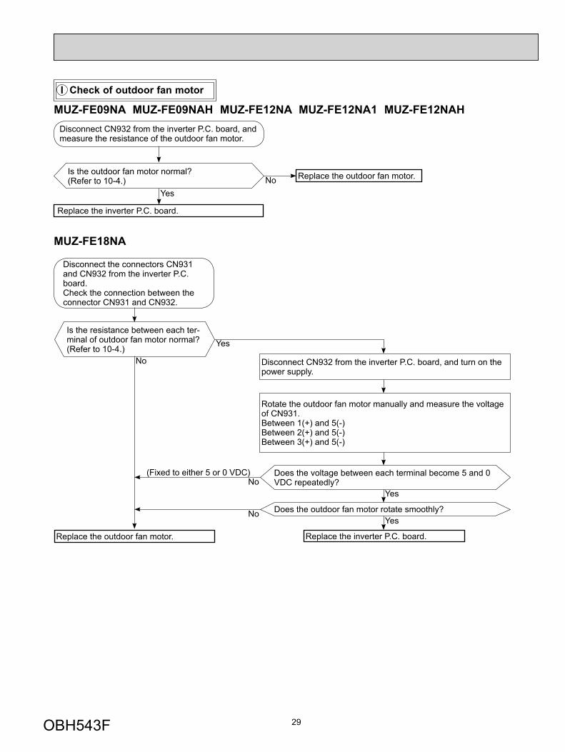
I Check of outdoor fan motor
Is the outdoor fan motor normal?(Refer to 10-4.) Replace the outdoor fan motor.
Disconnect CN932 from the inverter P.C. board, and measure the resistance of the outdoor fan motor.
Replace the inverter P.C. board.
NoYes
MUZ-FE09NA MUZ-FE09NAH MUZ-FE12NA MUZ-FE12NA1 MUZ-FE12NAH
MUZ-FE18NA
Is the resistance between each ter-minal of outdoor fan motor normal? (Refer to 10-4.)
Disconnect CN932 from the inverter P.C. board, and turn on the power supply.
Rotate the outdoor fan motor manually and measure the voltage of CN931.Between 1(+) and 5(-)Between 2(+) and 5(-)Between 3(+) and 5(-)
Does the voltage between each terminal become 5 and 0 VDC repeatedly?
Does the outdoor fan motor rotate smoothly?
Replace the outdoor fan motor. Replace the inverter P.C. board.
Yes
Yes
No(Fixed to either 5 or 0 VDC)
No
No
Yes
Disconnect the connectors CN931 and CN932 from the inverter P.C. board.Check the connection between the connector CN931 and CN932.
OBH543F

30
J Check of power supply
Is there voltage 208/230 VAC between the indoor terminal block S1 and S2? No
YesReplace the indoor electronic control P.C. board.
Rectify indoor/outdoor connecting wire.
Yes
If light up, OK.If fl ash, refer to 10-3.
Does POWER lamp on the indoor unit light up?
Does LED on the inverter P.C. board light up or fl ash? (Refer to 10-6.1.) No
Replace the inverter P.C. board.
Is there bus-bar voltage 260-325 VDC between DB61 (+) and DB61 (–) on the inverter P.C. board?(Refer to 10-6.1.)
No
Check the electric parts in main circuit.
Yes
Yes
No
Disconnect the connector (CN61) between compressor and intelligent power module.Turn ON power supply and pressEMERGENCY OPERATION switch.
Inverter P.C. board(Solder side)
DB61
260-325VDC
MUZ-FE09NA MUZ-FE09NAH MUZ-FE12NA MUZ-FE12NA1 MUZ-FE12NAH
OBH543F
31
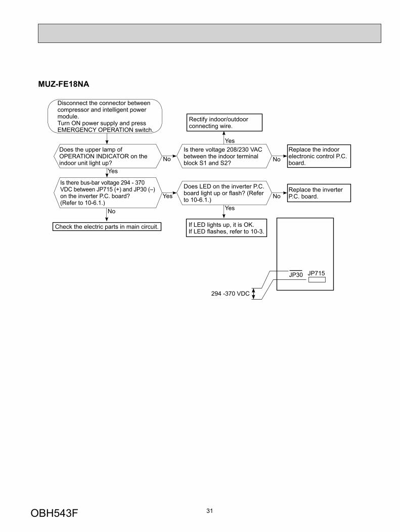
MUZ-FE18NA
Is there voltage 208/230 VAC between the indoor terminal block S1 and S2? No
YesReplace the indoor electronic control P.C. board.
Rectify indoor/outdoor connecting wire.
Yes
If LED lights up, it is OK.If LED fl ashes, refer to 10-3.
Does the upper lamp of OPERATION INDICATOR on the indoor unit light up?
Does LED on the inverter P.C. board light up or fl ash? (Refer to 10-6.1.) No
Replace the inverter P.C. board.
Is there bus-bar voltage 294 - 370 VDC between JP715 (+) and JP30 (–) on the inverter P.C. board?(Refer to 10-6.1.)
No
Check the electric parts in main circuit.
Yes
Yes
No
Disconnect the connector between compressor and intelligent power module.Turn ON power supply and pressEMERGENCY OPERATION switch.
294 -370 VDC
JP30 JP715
OBH543F

32
Press OPERATE/STOP (ON/OFF) button of the remote controller (the set temperature is displayed) with the remote controller headed towards the indoor unit. 1
Expansion valve operates in full-opening direction.
OK
NOTE: After check of LEV, do the undermentioned operations. 1. Turn OFF the power supply and turn ON it again. 2. Press RESET button on the remote controller.
1. Regardless of normal or abnormal condition, a short beep is emitted once the signal is received.
Measure each voltage between connector pins of CN724 on the inverter P.C. board.1. Pin (-) — Pin (+)2. Pin (-) — Pin (+)3. Pin (-) — Pin (+)4. Pin (-) — Pin (+)Is there about 3 ~ 5 VAC between each?NOTE: Measure the voltage by an analog
tester.
Properly fi x the LEV coil to the expansion valve.
Replace the inverter P.C. board.
Replace the LEV coil.
Replace the expansion valve.
Is LEV coil properly fi xed to the expansion valve?
Does the resistance of LEV coil have the characteristics?(Refer to 10-4.)
Do you hear the expansion valve "click, click·······"?Do you feel the expansion valve vibrate on touching it ?
Turn ON the power supply.<Preparation of the remote controller>
While pressing both OPERATION SELECT button and TOO COOL button on the remote controller at the same time, press RESET button.
First, release RESET button. Hold down the other two buttons for another 3 sec-
onds. Make sure that the indicators on the LCD screen shown in the right fi gure are all displayed.
Then release the buttons.
Yes
No
No
Yes
NoYes
No
Yes
K Check of LEV (Expansion valve) MSZ-FE09NAMSZ-FE12NA
MSZ-FE18NA
OBH543F
33
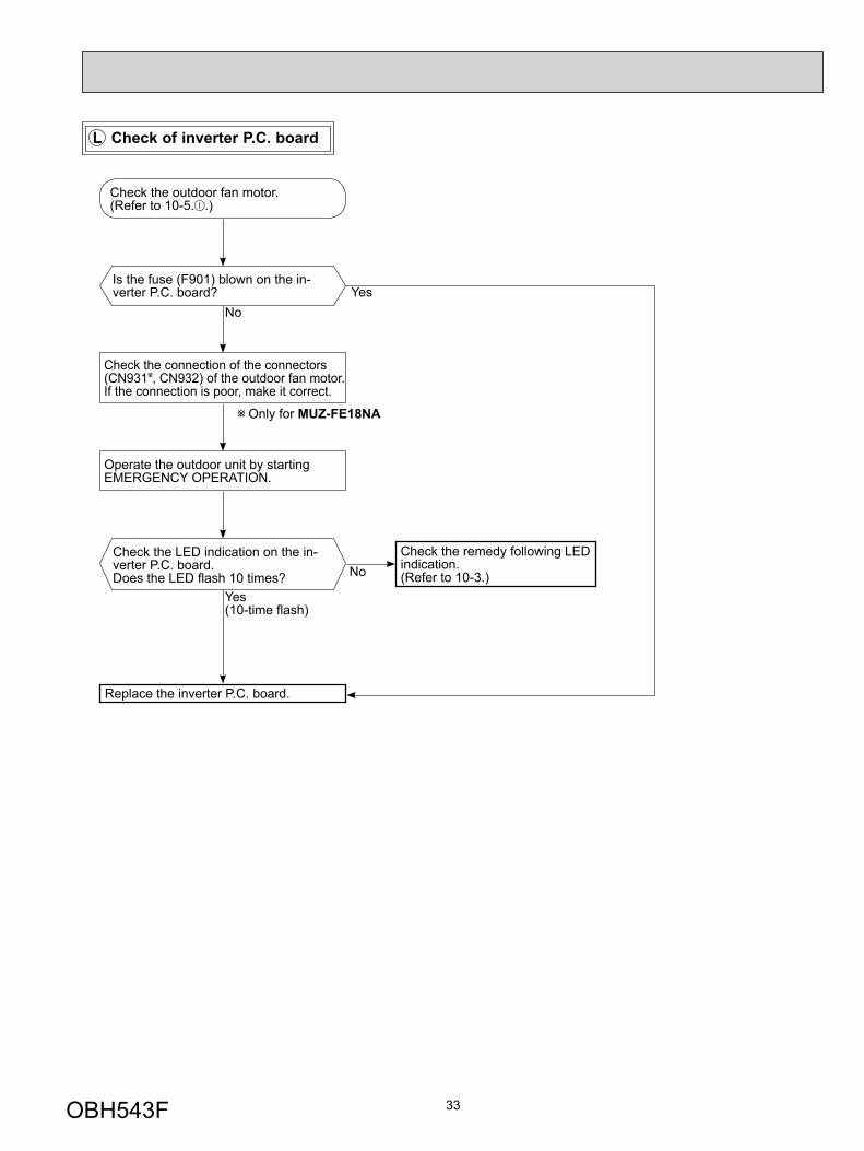
Check the outdoor fan motor. (Refer to 10-5. .)
Is the fuse (F901) blown on the in-verter P.C. board?
Check the connection of the connectors (CN931 , CN932) of the outdoor fan motor. If the connection is poor, make it correct.
Operate the outdoor unit by starting EMERGENCY OPERATION.
Check the LED indication on the in-verter P.C. board.Does the LED fl ash 10 times?
Replace the inverter P.C. board.
Check the remedy following LED indication.(Refer to 10-3.)
YesNo
Yes(10-time fl ash)
No
L Check of inverter P.C. board
Only for MUZ-FE18NA
OBH543F

34
M How to check miswiring and serial signal error
• Turn OFF inverter-controlled lighting equipment.
• Turn OFF the power supply and then turn ON again.
• Press EMERGENCY OPERATION switch.
A
Is serial signal error indicated 6 minutes later?
B
Yes
• Reinstall either the unit or the light away from each other.
• Attach a fi lter on remote control receiv-ing section of the indoor unit.
No
Turn OFF the power supply.
Is there rated voltage in the power supply?Yes
No
Turn ON the power supply.
Check the power supply.
Is there rated voltage between outdoor terminal block S1 and S2? No Check the wiring.
Press EMERGENCY OPERATION switch once.
Does the OPERATION INDICATOR lamp light up? <Confi rmation of the power to the indoor unit>
YesNo
Is serial signal error indicated 6 minutes later?
YesNo
Is there any miswiring, poor contact, or wire disconnection of the indoor/outdoor connect-ing wire?
Yes Correct them.
No
A
Turn OFF the power supply.Check once more if the indoor/outdoor connecting wire is not miswiring.Bridge the outdoor terminal block S2 and S3. 1
B
1. Miswiring may damage indoor electronic control P.C. board during the operation.Be sure to confi rm the wiring is correct before the opera-tion starts.
Turn ON the power supply.
Does the LED on the inverter P.C. board repeat "3.6-second-OFF and 0.8-second-ON quick blinking"? 3
YesNo(Lighted or not lighted)
Replace the inverter P.C. board. 2
2. Be careful of the residual voltage of smoothing capacitor.
Turn OFF the power supply.Remove the bridge between outdoor terminal block S2 and S3.
Yes
3. Be sure to check this within 3 minutes after turning ON. After 3 minutes, LED blinks 6 times. Even when the inverter P.C. board or the outdoor electronic control P.C. board is normal, LED blinks 6 times after 3 minutes.
Is the bus-bar voltage of the inverter P.C. board normal(Refer to "TEST POINT DIAGRAM AND VOLTAGE" in this manual.) ? No
Yes
Replace the indoor electronic control P.C. board.
OBH543F
35
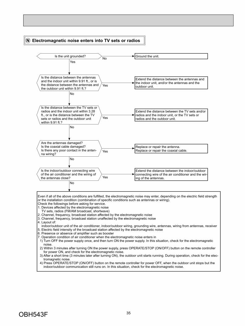
N Electromagnetic noise enters into TV sets or radios
Yes
Is the unit grounded?No Ground the unit.
Yes
Is the distance between the antennas and the indoor unit within 9.91 ft., or is the distance between the antennas and the outdoor unit within 9.91 ft.?
No
Extend the distance between the antennas and the indoor unit, and/or the antennas and the outdoor unit.
Is the distance between the TV sets or radios and the indoor unit within 3.28 ft., or is the distance between the TV sets or radios and the outdoor unit within 9.91 ft.?
Yes
Extend the distance between the TV sets and/or radios and the indoor unit, or the TV sets or radios and the outdoor unit.
Are the antennas damaged?Is the coaxial cable damaged?Is there any poor contact in the anten-na wiring?
Yes
No
No
Replace or repair the antenna.Replace or repair the coaxial cable.
Is the indoor/outdoor connecting wire of the air conditioner and the wiring of the antennas close? Yes
Extend the distance between the indoor/outdoor connecting wire of the air conditioner and the wir-ing of the antennas.
No
Even if all of the above conditions are fulfi lled, the electromagnetic noise may enter, depending on the electric fi eld strength or the installation condition (combination of specifi c conditions such as antennas or wiring).Check the followings before asking for service.1. Devices affected by the electromagnetic noise TV sets, radios (FM/AM broadcast, shortwave)2. Channel, frequency, broadcast station affected by the electromagnetic noise3. Channel, frequency, broadcast station unaffected by the electromagnetic noise4. Layout of: indoor/outdoor unit of the air conditioner, indoor/outdoor wiring, grounding wire, antennas, wiring from antennas, receiver5. Electric fi eld intensity of the broadcast station affected by the electromagnetic noise6. Presence or absence of amplifi er such as booster7. Operation condition of air conditioner when the electromagnetic noise enters in
1) Turn OFF the power supply once, and then turn ON the power supply. In this situation, check for the electromagnetic noise.
2) Within 3 minutes after turning ON the power supply, press OPERATE/STOP (ON/OFF) button on the remote controller for power ON, and check for the electromagnetic noise.
3) After a short time (3 minutes later after turning ON), the outdoor unit starts running. During operation, check for the elec-tromagnetic noise.
4) Press OPERATE/STOP (ON/OFF) button on the remote controller for power OFF, when the outdoor unit stops but the indoor/outdoor communication still runs on. In this situation, check for the electromagnetic noise.
OBH543F
36
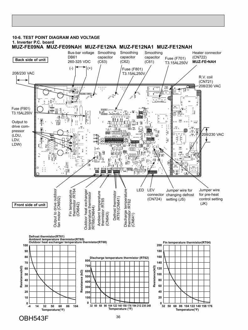
10-6. TEST POINT DIAGRAM AND VOLTAGE
-4 14 32 50 68 86 1040
10
20
30
40
50
60
70
80
90
100
Temperature(°F)
Defrost thermistor(RT61)Ambient temperature thermistor(RT65)Outdoor heat exchanger temperature thermistor(RT68)
32 50 68 86 104 122 140 158 1760
20
40
60
80
100
120
140
160
180
200
Temperature(°F)
Fin temperature thermistor(RT64)
Temperature (°F)
Discharge temperature thermistor (RT62)
0
100
200
300
400
500
600
700
800
32 60 68 86 104 122 140 158 176 194 212 230 248
1. Inverter P.C. boardMUZ-FE09NA MUZ-FE09NAH MUZ-FE12NA MUZ-FE12NA1 MUZ-FE12NAH
Back side of unit
Fin
tem
pera
ture
th
erm
isto
r /R
T64
(CN
642)
Am
bien
t tem
pera
ture
th
erm
isto
r /R
T65
(CN
643)
Dis
char
ge te
mpe
ratu
re
ther
mis
tor /
RT6
2 (C
N64
1)
Def
rost
ther
mis
tor
/RT6
1(C
N64
1)
LEV connector (CN724)
Bus-bar voltageDB61260-325 VDC
Front side of unit
208/230 VAC
Smoothing capacitor(C62)
Output to drive com-pressor(LDU,LDV,LDW)
(+)(-)
Fuse (F701)T3.15AL250V
Smoothing capacitor(C61)
Smoothing capacitor(C63)
Fuse (F801)T3.15AL250V
R.V. coil (CN721)208/230 VAC
Jumper wire for changing defrost setting (JS)
Out
put t
o dr
ive
outd
oor
fan
mot
or (C
N93
2)
208/230 VAC
Out
door
hea
t exc
hang
er
tem
pera
ture
ther
mis
tor
/RT6
8(C
N64
4)
Jumper wire for pre-heat control setting (JK)
Fuse (F901)T3.15AL250V
LED
Heater connector(CN722)MUZ-FE•NAH
OBH543F
37
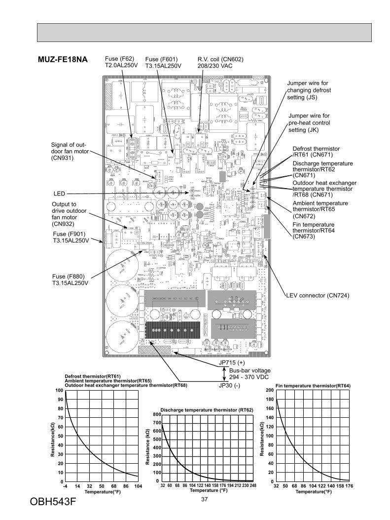
MUZ-FE18NA
-4 14 32 50 68 86 1040
10
20
30
40
50
60
70
80
90
100
Temperature(°F)
Defrost thermistor(RT61)Ambient temperature thermistor(RT65)Outdoor heat exchanger temperature thermistor(RT68)
32 50 68 86 104 122 140 158 1760
20
40
60
80
100
120
140
160
180
200
Temperature(°F)
Fin temperature thermistor(RT64)
Temperature (°F)
Discharge temperature thermistor (RT62)
0
100
200
300
400
500
600
700
800
32 60 68 86 104 122 140 158 176 194 212 230 248
Fin temperaturethermistor/RT64(CN673)
Ambient temperature thermistor/RT65(CN672)
Discharge temperature thermistor/RT62(CN671)
Defrost thermistor /RT61 (CN671)
Output to drive outdoor fan motor (CN932)
Outdoor heat exchanger temperature thermistor /RT68 (CN671)
Fuse (F901)T3.15AL250V
Fuse (F880)T3.15AL250V
LEV connector (CN724)
Jumper wire for changing defrost setting (JS)
Jumper wire for pre-heat control setting (JK)
Fuse (F62)T2.0AL250V
Fuse (F601)T3.15AL250V
Signal of out-door fan motor (CN931)
R.V. coil (CN602)208/230 VAC
Bus-bar voltage294 - 370 VDC
JP715 (+)
JP30 (-)
LED
OBH543F

38
11-1. MUZ-FE09NA MUZ-FE09NAH MUZ-FE12NA MUZ-FE12NA1 MUZ-FE12NAHNOTE: Turn OFF power supply before disassembly.
OPERATING PROCEDURE PHOTOS1. Removing the cabinet
(1) Remove the screw fixing the service panel.(2) Pull down the service panel and remove it.(3) Remove the screws fixing the conduit cover.(4) Remove the conduit cover.(5) Disconnect the power supply wire and indoor/outdoor
connecting wire.(6) Remove the screws fixing the top panel.(7) Remove the top panel.(8) Remove the screws fixing the cabinet.(9) Remove the cabinet.(10) Remove the screws fixing the back panel.(11) Remove the back panel.
Photo 1
Screws of the cabinet
Back panel
Service panel
Screws of the top panel
Screws of the top panel
Photo 3
Screws of the conduit cover
Conduit plateConduit cover
11 DISASSEMBLY INSTRUCTIONS
(1) Slide the sleeve and check if there is a locking lever or not. (2) The terminal with this connector has the locking mechanism.
Slide the sleeve.Pull the terminal while pushing the lockinglever.
Hold the sleeve, and pull out the terminal slowly.
Connector
Sleeve
Locking lever
<"Terminal with locking mechanism" Detaching points>The terminal which has the locking mechanism can be detached as shown below.There are two types (refer to (1) and (2)) of the terminal with locking mechanism.The terminal without locking mechanism can be detached by pulling it out.Check the shape of the terminal before detaching.
Screw of the service panel
Direction to remove
Screws of the cabinet
Hooks
Screw of the cabinet
Screws of the terminal block support and the back panel
Photo 2
Screws of the back panel
OBH543F
39
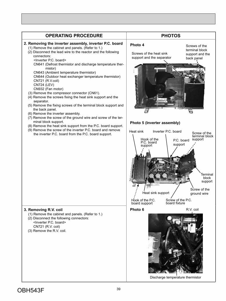
OPERATING PROCEDURE PHOTOS2. Removing the inverter assembly, inverter P.C. board
(1) Remove the cabinet and panels. (Refer to 1.)(2) Disconnect the lead wire to the reactor and the following
connectors:<Inverter P.C. board>CN641 (Defrost thermistor and discharge temperature ther-
mistor)CN643 (Ambient temperature thermistor) CN644 (Outdoor heat exchanger temperature thermistor)CN721 (R.V.coil)CN724 (LEV)CN932 (Fan motor)
(3) Remove the compressor connector (CN61).(4) Remove the screws fixing the heat sink support and the
separator.(5) Remove the fixing screws of the terminal block support and
the back panel.(6) Remove the inverter assembly.(7) Remove the screw of the ground wire and screw of the ter-
minal block support.(8) Remove the heat sink support from the P.C. board support.(9) Remove the screw of the inverter P.C. board and remove
the inverter P.C. board from the P.C. board support.
3. Removing R.V. coil (1) Remove the cabinet and panels. (Refer to 1.)(2) Disconnect the following connectors: <Inverter P.C. board>
CN721 (R.V. coil)(3) Remove the R.V. coil.
Photo 6
Discharge temperature thermistor
Photo 4
Photo 5 (Inverter assembly)
R.V. coil
Screws of the heat sink support and the separator
Screws of the terminal block support and the back panel
Heat sink Inverter P.C. board
Screw of the ground wire
Terminal block
support
Heat sink support
P.C. board support
Hook of the P.C. board support
Hook of the P.C. board support
Screw of the P.C. board fixture
Screw of the terminal block support
OBH543F
40
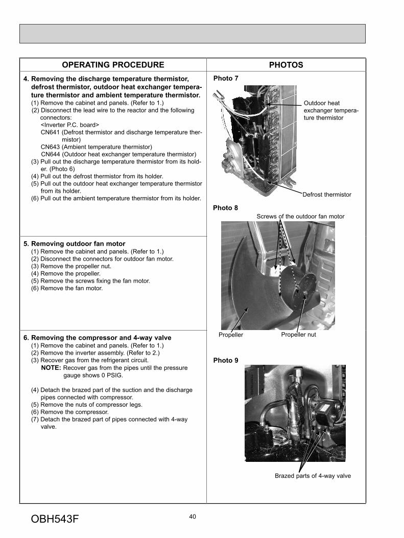
OPERATING PROCEDURE PHOTOS4. Removing the discharge temperature thermistor,
defrost thermistor, outdoor heat exchanger tempera-ture thermistor and ambient temperature thermistor.(1) Remove the cabinet and panels. (Refer to 1.)(2) Disconnect the lead wire to the reactor and the following
connectors:<Inverter P.C. board>CN641 (Defrost thermistor and discharge temperature ther-
mistor)CN643 (Ambient temperature thermistor) CN644 (Outdoor heat exchanger temperature thermistor)
(3) Pull out the discharge temperature thermistor from its hold-er. (Photo 6)
(4) Pull out the defrost thermistor from its holder.(5) Pull out the outdoor heat exchanger temperature thermistor
from its holder. (6) Pull out the ambient temperature thermistor from its holder.
5. Removing outdoor fan motor(1) Remove the cabinet and panels. (Refer to 1.)(2) Disconnect the connectors for outdoor fan motor.(3) Remove the propeller nut.(4) Remove the propeller.(5) Remove the screws fixing the fan motor.(6) Remove the fan motor.
6. Removing the compressor and 4-way valve(1) Remove the cabinet and panels. (Refer to 1.)(2) Remove the inverter assembly. (Refer to 2.)(3) Recover gas from the refrigerant circuit.
NOTE: Recover gas from the pipes until the pressure gauge shows 0 PSIG.
(4) Detach the brazed part of the suction and the discharge pipes connected with compressor.
(5) Remove the nuts of compressor legs.(6) Remove the compressor.(7) Detach the brazed part of pipes connected with 4-way
valve.
Photo 7
Photo 9
Photo 8
Defrost thermistor
Outdoor heat exchanger tempera-ture thermistor
Brazed parts of 4-way valve
Propeller nut
Screws of the outdoor fan motor
Propeller
OBH543F
41
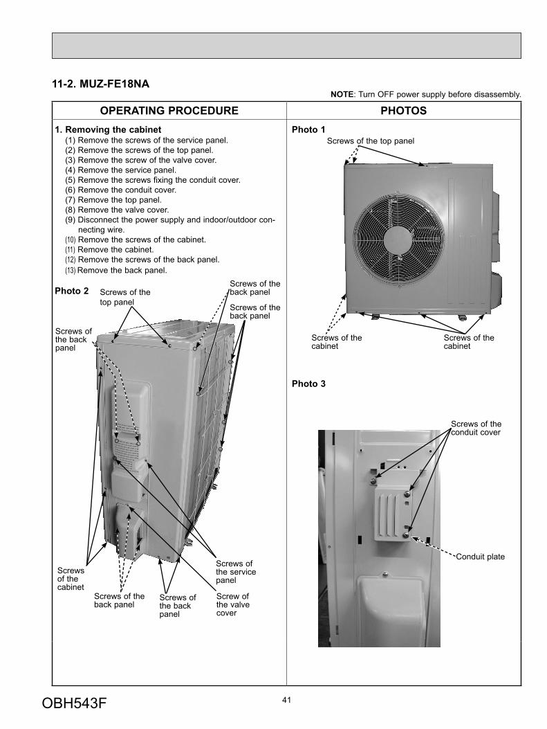
11-2. MUZ-FE18NANOTE: Turn OFF power supply before disassembly.
OPERATING PROCEDURE PHOTOS1. Removing the cabinet
(1) Remove the screws of the service panel.(2) Remove the screws of the top panel.(3) Remove the screw of the valve cover.(4) Remove the service panel.(5) Remove the screws fixing the conduit cover.(6) Remove the conduit cover.(7) Remove the top panel.(8) Remove the valve cover.(9) Disconnect the power supply and indoor/outdoor con-
necting wire.(10) Remove the screws of the cabinet.(11) Remove the cabinet.(12) Remove the screws of the back panel.(13) Remove the back panel.
Photo 2
Photo 1
Photo 3
Screws of the cabinet
Screws of the top panel
Screws of the cabinet
Screws of the top panel
Screws of the back panel
Screws of the service panel
Screws of the back panel
Screws of the cabinet
Screws of the back panel
Screws of the back panel
Screws of the conduit cover
Conduit plate
Screws of the back panel
Screw of the valve cover
OBH543F

42
OPERATING PROCEDURE PHOTOS2. Removing the inverter assembly, inverter P.C. board
(1) Remove the cabinet and panels. (Refer to 1.)(2) Disconnect the lead wire to the reactor and the following con-
nectors:<Inverter P.C. board>CN602 (R.V. coil)CN671 (Defrost thermistor, discharge temperature thermistor
and outdoor heat exchanger temperature thermistor)CN672 (Ambient temperature thermistor) CN724 (LEV)CN931, CN932 (Fan motor)
(3) Remove the compressor connector.(4) Remove the screws fixing the relay panel.(5) Remove the relay panel.(6) Remove the earth wires and the lead wires of the inverter P.C.
board.(7) Remove the screws of the PB support.(8) Remove the inverter P.C. board from the relay panel.
Photo 4
Photo 5
3. Removing R.V. coil (1) Remove the cabinet and panels. (Refer to 1.)(2) Disconnect the following connector: <Inverter P.C. board>
CN602 (R.V. coil)(3) Remove the R.V. coil.
Screws of the PB support
Screws of the relay panel
Inverter P.C board Earth wires
Screw of the relay panel
Screws of the PB support
Brazed parts of 4-way valve
Screw of the R.V. coil
OBH543F

43
OPERATING PROCEDURE PHOTOS4. Removing the discharge temperature thermistor,
defrost thermistor, outdoor heat exchanger tempera-ture thermistor and ambient temperature thermistor(1) Remove the cabinet and panels. (Refer to 1.)(2) Disconnect the lead wire to the reactor and the following
connectors:<Inverter P.C. board>CN671 (Defrost thermistor, discharge temperature thermis-
tor and outdoor heart exchanger temperature ther-mistor)
CN672 (Ambient temperature thermistor) (3) Pull out the discharge temperature thermistor from its holder. (Photo 8)(4) Pull out the defrost thermistor from its holder. (5) Pull out the outdoor heat exchanger temperature thermistor
from its holder. (6) Pull out the ambient temperature thermistor from its holder.
Photo 6
Photo 7
Photo 8
5. Removing outdoor fan motor(1) Remove the top panel, cabinet and service panel. (Refer to 1.)(2) Disconnect the following connectors:
<Inverter P.C. board>CN931 and CN932 (Fan motor)
(3) Remove the propeller.(4) Remove the screws fixing the fan motor.(5) Remove the fan motor.
6. Removing the compressor and 4-way valve(1) Remove the top panel, cabinet and service panel. (Refer to 1.)(2) Remove the back panel. (Refer to 1.)(3) Remove the inverter assembly. (Refer to 2.)(4) Recover gas from the refrigerant circuit.NOTE: Recover gas from the pipes until the pressure gauge
shows 0 kg/cm2 (0 MPa).(5) Detach the brazed part of the suction and the discharge
pipes connected with compressor.(6) Remove the compressor nuts.(7) Remove the compressor.(8) Detach the brazed parts of 4-way valve and pipes. (Photo 5)
Screws of the outdoor fan motor
Brazed part of the discharge pipe
Brazed part of the suction pipe
Discharge temperature thermistor
Outdoor heat exchanger tempera-ture thermistor
Ambient tem-peraturethermistor
Defrost thermistor
OBH543F

HEAD OFFICE: TOKYO BLDG., 2-7-3, MARUNOUCHI, CHIYODA-KU, TOKYO 100-8310, JAPAN
© Copyright 2009 MITSUBISHI ELECTRIC CORPORATIONDistributed in Jan. 2015. No. OBH543 REVISED EDITION-FDistributed in Dec. 2012. No. OBH543 REVISED EDITION-EDistributed in Apr. 2012. No. OBH543 REVISED EDITION-DDistributed in Apr. 2011. No. OBH543 REVISED EDITION-CDistributed in Apr. 2011. No. OBH543 REVISED EDITION-BDistributed in Sep. 2010. No. OBH543 REVISED EDITION-A 5Distributed in Jul. 2009. No. OBH543 5Made in Japan
New publication, effective Jan. 2015Specifications are subject to change without notice.