Embed Size (px)
Citation preview
HGM1750
Genset Security Module
USER MANUAL
Smartgen Technology
CONTENT
1. SUMMARY .......................................................................................................... 4
2. PERFORMANCE AND CHARACTERISTICS .................................................... 5
3. SPECIFICATION ................................................................................................. 7
4. OPERATION ....................................................................................................... 8
5. PROTECTION ..................................................................................................... 9
6. PARAMETER RANGE AND DEFINATION ....................................................... 11
6.1 PARAMETER DEFINITION AND RANGE ......................................................... 11
6.2 PROGRAMMABLE INPUT ................................................................................ 13
6.3 SENSOR SELECTION ...................................................................................... 14
7. CONNECTIONS ................................................................................................ 15
8. CASE DIMENSIONS (PANEL CUTOUT 78*66MM) ......................................... 16
9. TYPICAL APPLICATION .................................................................................. 17
1. SUMMARY
HGM1750 Genset Security Module is a security module that can display electrical
parameters (e.g. voltage, speed, temperature, oil pressure and fuel level) and stop
the unit when faults occurs (e.g. low oil pressure, high water/cylinder temperature,
emergency stop and over speed). Graphical LCD monitor on the front panel displays
fault conditions and provides effective alarm signals.
2. PERFORMANCE AND CHARACTERISTICS
◙ Based on microprocessor, fitted with LCD screen with graphic icons and blue
backlight which can display engine parameters and alarms;
◙ Power supply range (8~35)VDC,compatibility with 12V or 24V starter batteries;
◙ Generator input port; speed, temperature, pressure, liquid level sensor input ports;
digitalized electric quantity display.
Measured and displayed electric quantity:
Generator voltage V
Generator frequency Hz
Engine temperature ºC
Oil pressure kPa
Engine Speed rpm
Total running time
Battery voltage
Fuel level
◆ Generator voltage, battery voltage, engine speed, temperature, pressure, liquid
level threshold value can be set.
Warnings and alarms are as following:
High temperature
Low oil pressure
Low fuel level
Generator over voltage
Generator over frequency
Over speed
Emergency shutdown
Fail to stop
Charge Alt Fail
Battery over voltage
Battery under voltage
◙ The controller can be set as an engine controller via software (generator voltage
input is deactivated);
◙ Running status and alarm status are indicated by red LED on the panel;
◙ Charging generator excitation function;
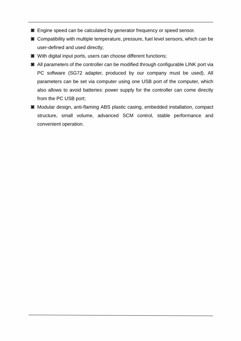
◙ Engine speed can be calculated by generator frequency or speed sensor.
◙ Compatibility with multiple temperature, pressure, fuel level sensors, which can be
user-defined and used directly;
◙ With digital input ports, users can choose different functions;
◙ All parameters of the controller can be modified through configurable LINK port via
PC software (SG72 adapter, produced by our company must be used). All
parameters can be set via computer using one USB port of the computer, which
also allows to avoid batteries: power supply for the controller can come directly
from the PC USB port;
◙ Modular design, anti-flaming ABS plastic casing, embedded installation, compact
structure, small volume, advanced SCM control, stable performance and
convenient operation.
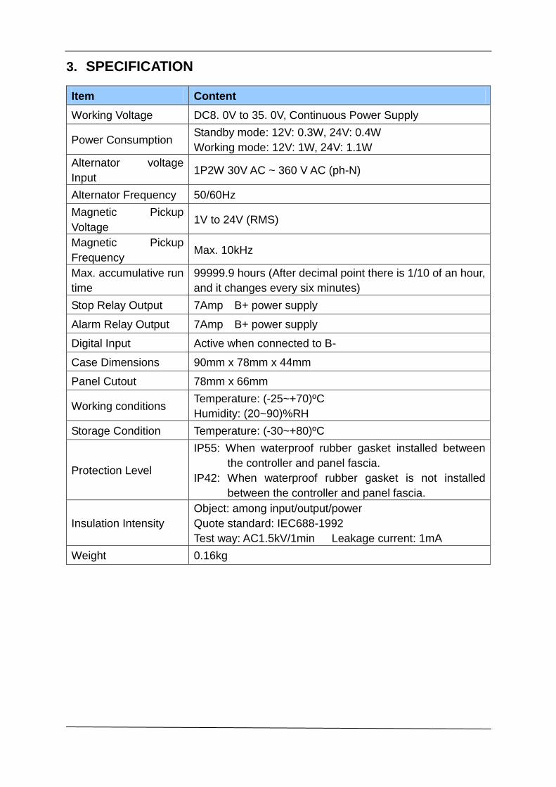
3. SPECIFICATION
Item Content
Working Voltage DC8. 0V to 35. 0V, Continuous Power Supply
Power Consumption Standby mode: 12V: 0.3W, 24V: 0.4W
Working mode: 12V: 1W, 24V: 1.1W
Alternator voltage
Input 1P2W 30V AC ~ 360 V AC (ph-N)
Alternator Frequency 50/60Hz
Magnetic Pickup
Voltage 1V to 24V (RMS)
Magnetic Pickup
Frequency Max. 10kHz
Max. accumulative run
time
99999.9 hours (After decimal point there is 1/10 of an hour,
and it changes every six minutes)
Stop Relay Output 7Amp B+ power supply
Alarm Relay Output 7Amp B+ power supply
Digital Input Active when connected to B-
Case Dimensions 90mm x 78mm x 44mm
Panel Cutout 78mm x 66mm
Working conditions Temperature: (-25~+70)ºC
Humidity: (20~90)%RH
Storage Condition Temperature: (-30~+80)ºC
Protection Level
IP55: When waterproof rubber gasket installed between
the controller and panel fascia.
IP42: When waterproof rubber gasket is not installed
between the controller and panel fascia.
Insulation Intensity
Object: among input/output/power
Quote standard: IEC688-1992
Test way: AC1.5kV/1min Leakage current: 1mA
Weight 0.16kg
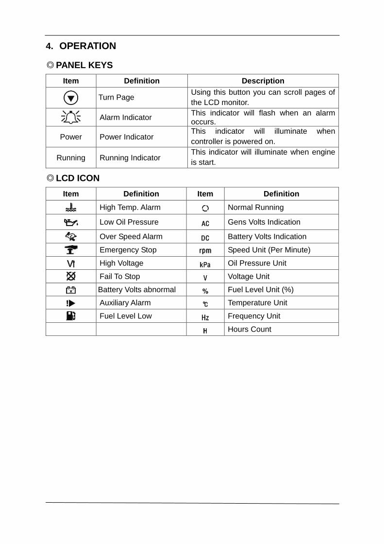
4. OPERATION
◎ PANEL KEYS
Item Definition Description
Turn Page Using this button you can scroll pages of
the LCD monitor.
Alarm Indicator This indicator will flash when an alarm occurs.
Power Power Indicator This indicator will illuminate when
controller is powered on.
Running Running Indicator This indicator will illuminate when engine
is start.
◎ LCD ICON
Item Definition Item Definition
High Temp. Alarm Normal Running
Low Oil Pressure Gens Volts Indication
Over Speed Alarm Battery Volts Indication
Emergency Stop Speed Unit (Per Minute)
High Voltage Oil Pressure Unit
Fail To Stop Voltage Unit
Battery Volts abnormal Fuel Level Unit (%)
Auxiliary Alarm Temperature Unit
Fuel Level Low Frequency Unit
Hours Count
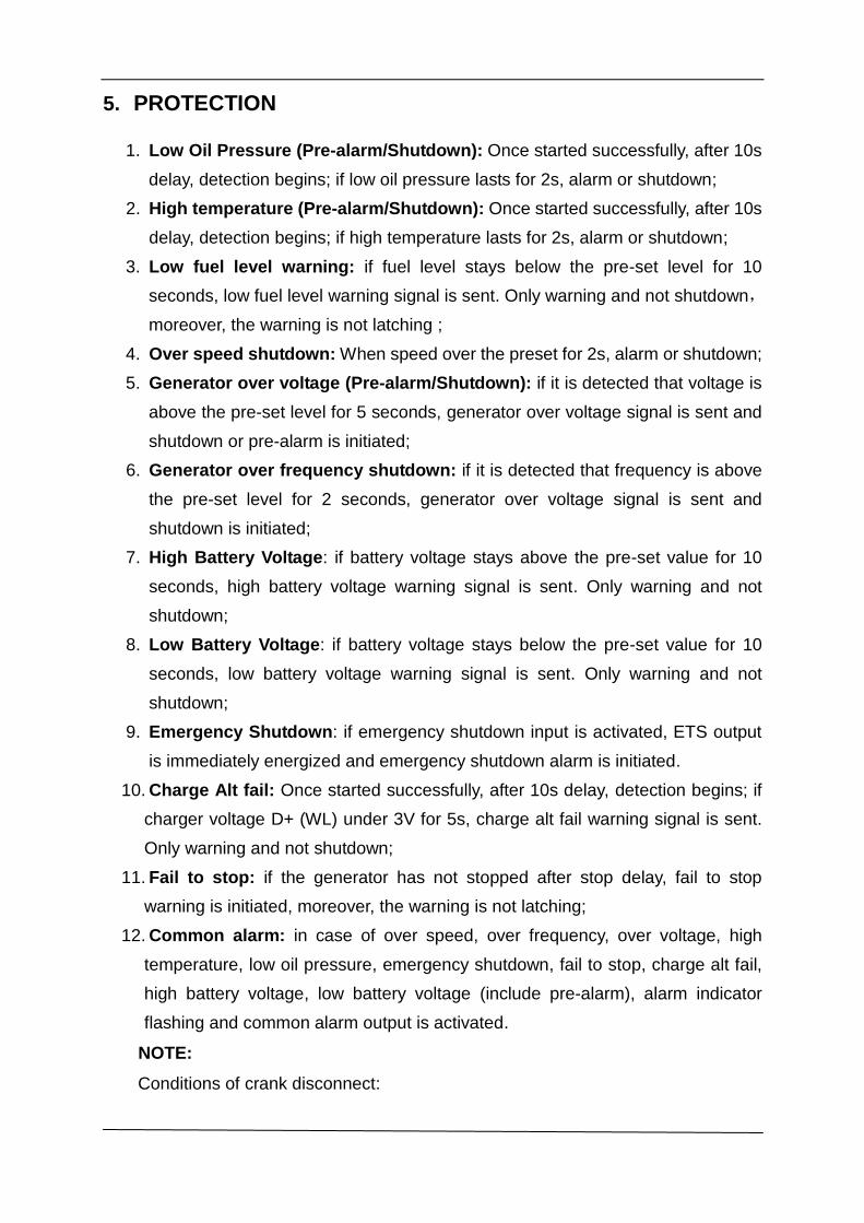
5. PROTECTION
1. Low Oil Pressure (Pre-alarm/Shutdown): Once started successfully, after 10s
delay, detection begins; if low oil pressure lasts for 2s, alarm or shutdown;
2. High temperature (Pre-alarm/Shutdown): Once started successfully, after 10s
delay, detection begins; if high temperature lasts for 2s, alarm or shutdown;
3. Low fuel level warning: if fuel level stays below the pre-set level for 10
seconds, low fuel level warning signal is sent. Only warning and not shutdown,
moreover, the warning is not latching ;
4. Over speed shutdown: When speed over the preset for 2s, alarm or shutdown;
5. Generator over voltage (Pre-alarm/Shutdown): if it is detected that voltage is
above the pre-set level for 5 seconds, generator over voltage signal is sent and
shutdown or pre-alarm is initiated;
6. Generator over frequency shutdown: if it is detected that frequency is above
the pre-set level for 2 seconds, generator over voltage signal is sent and
shutdown is initiated;
7. High Battery Voltage: if battery voltage stays above the pre-set value for 10
seconds, high battery voltage warning signal is sent. Only warning and not
shutdown;
8. Low Battery Voltage: if battery voltage stays below the pre-set value for 10
seconds, low battery voltage warning signal is sent. Only warning and not
shutdown;
9. Emergency Shutdown: if emergency shutdown input is activated, ETS output
is immediately energized and emergency shutdown alarm is initiated.
10. Charge Alt fail: Once started successfully, after 10s delay, detection begins; if
charger voltage D+ (WL) under 3V for 5s, charge alt fail warning signal is sent.
Only warning and not shutdown;
11. Fail to stop: if the generator has not stopped after stop delay, fail to stop
warning is initiated, moreover, the warning is not latching;
12. Common alarm: in case of over speed, over frequency, over voltage, high
temperature, low oil pressure, emergency shutdown, fail to stop, charge alt fail,
high battery voltage, low battery voltage (include pre-alarm), alarm indicator
flashing and common alarm output is activated.
NOTE:
Conditions of crank disconnect:
1. When oil pressure is over 200kPa;
2. When generator frequency is over 40% of the rated frequency (e.g. set as
20Hz if the rated is 50Hz);
3. When engine speed is over 40% of the rated speed (e.g. set as 600rpm if the
rated is 1500rpm)
Any one of above is satisfied, crank disconnects and protection begins.
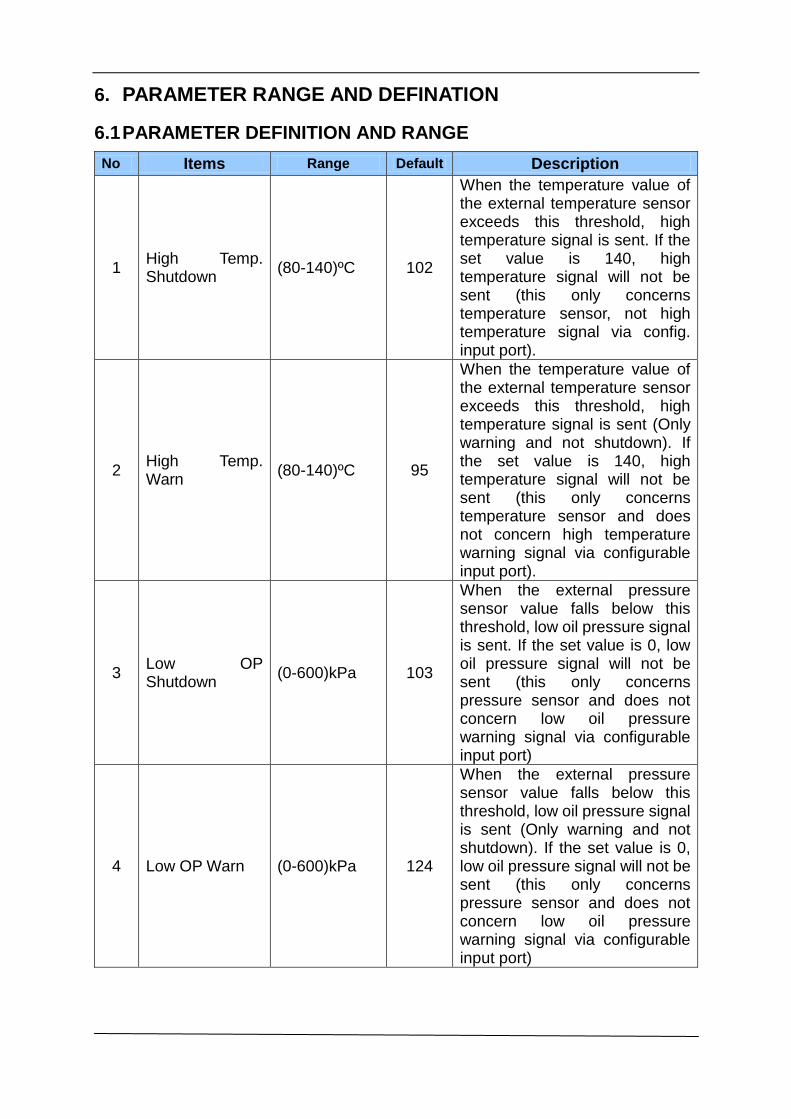
6. PARAMETER RANGE AND DEFINATION
6.1 PARAMETER DEFINITION AND RANGE
No Items Range Default Description
1 High Temp. Shutdown
(80-140)ºC 102
When the temperature value of the external temperature sensor exceeds this threshold, high temperature signal is sent. If the set value is 140, high temperature signal will not be sent (this only concerns temperature sensor, not high temperature signal via config. input port).
2 High Temp. Warn
(80-140)ºC 95
When the temperature value of the external temperature sensor exceeds this threshold, high temperature signal is sent (Only warning and not shutdown). If the set value is 140, high temperature signal will not be sent (this only concerns temperature sensor and does not concern high temperature warning signal via configurable input port).
3 Low OP Shutdown
(0-600)kPa 103
When the external pressure sensor value falls below this threshold, low oil pressure signal is sent. If the set value is 0, low oil pressure signal will not be sent (this only concerns pressure sensor and does not concern low oil pressure warning signal via configurable input port)
4 Low OP Warn (0-600)kPa 124
When the external pressure sensor value falls below this threshold, low oil pressure signal is sent (Only warning and not shutdown). If the set value is 0, low oil pressure signal will not be sent (this only concerns pressure sensor and does not concern low oil pressure warning signal via configurable input port)
No Items Range Default Description
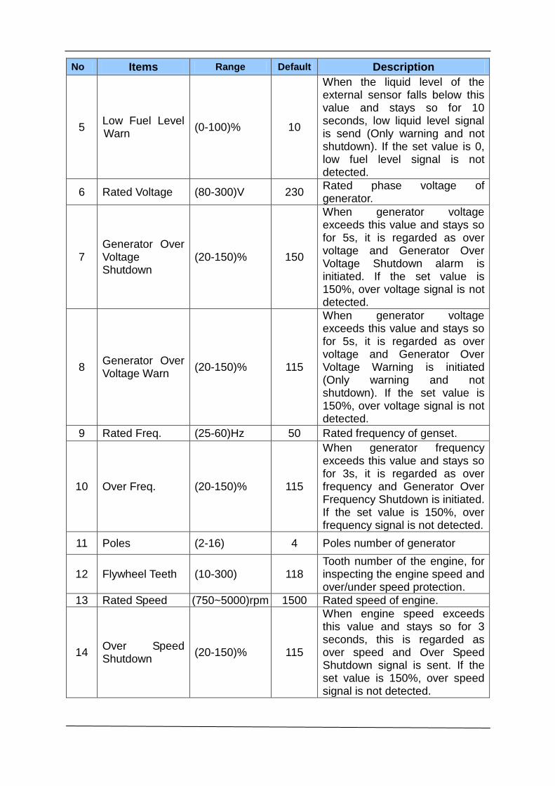
5 Low Fuel Level Warn
(0-100)% 10
When the liquid level of the external sensor falls below this value and stays so for 10 seconds, low liquid level signal is send (Only warning and not shutdown). If the set value is 0, low fuel level signal is not detected.
6 Rated Voltage (80-300)V 230 Rated phase voltage of generator.
7 Generator Over Voltage Shutdown
(20-150)% 150
When generator voltage exceeds this value and stays so for 5s, it is regarded as over voltage and Generator Over Voltage Shutdown alarm is initiated. If the set value is 150%, over voltage signal is not detected.
8 Generator Over Voltage Warn
(20-150)% 115
When generator voltage exceeds this value and stays so for 5s, it is regarded as over voltage and Generator Over Voltage Warning is initiated (Only warning and not shutdown). If the set value is 150%, over voltage signal is not detected.
9 Rated Freq. (25-60)Hz 50 Rated frequency of genset.
10 Over Freq. (20-150)% 115
When generator frequency exceeds this value and stays so for 3s, it is regarded as over frequency and Generator Over Frequency Shutdown is initiated. If the set value is 150%, over frequency signal is not detected.
11 Poles (2-16) 4 Poles number of generator
12 Flywheel Teeth (10-300) 118 Tooth number of the engine, for inspecting the engine speed and over/under speed protection.
13 Rated Speed (750~5000)rpm 1500 Rated speed of engine.
14 Over Speed Shutdown
(20-150)% 115
When engine speed exceeds this value and stays so for 3 seconds, this is regarded as over speed and Over Speed Shutdown signal is sent. If the set value is 150%, over speed signal is not detected.
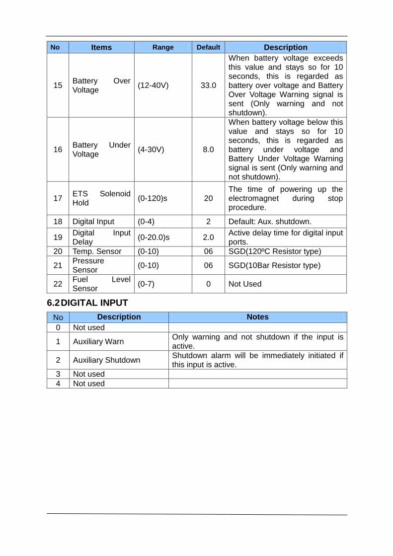
No Items Range Default Description
15 Battery Over Voltage
(12-40V) 33.0
When battery voltage exceeds this value and stays so for 10 seconds, this is regarded as battery over voltage and Battery Over Voltage Warning signal is sent (Only warning and not shutdown).
16 Battery Under Voltage
(4-30V) 8.0
When battery voltage below this value and stays so for 10 seconds, this is regarded as battery under voltage and Battery Under Voltage Warning signal is sent (Only warning and not shutdown).
17 ETS Solenoid Hold
(0-120)s 20 The time of powering up the electromagnet during stop procedure.
18 Digital Input (0-4) 2 Default: Aux. shutdown.
19 Digital Input Delay
(0-20.0)s 2.0 Active delay time for digital input ports.
20 Temp. Sensor (0-10) 06 SGD(120ºC Resistor type)
21 Pressure Sensor
(0-10) 06 SGD(10Bar Resistor type)
22 Fuel Level Sensor
(0-7) 0 Not Used
6.2 DIGITAL INPUT
No Description Notes
0 Not used
1 Auxiliary Warn Only warning and not shutdown if the input is active.
2 Auxiliary Shutdown Shutdown alarm will be immediately initiated if this input is active.
3 Not used
4 Not used
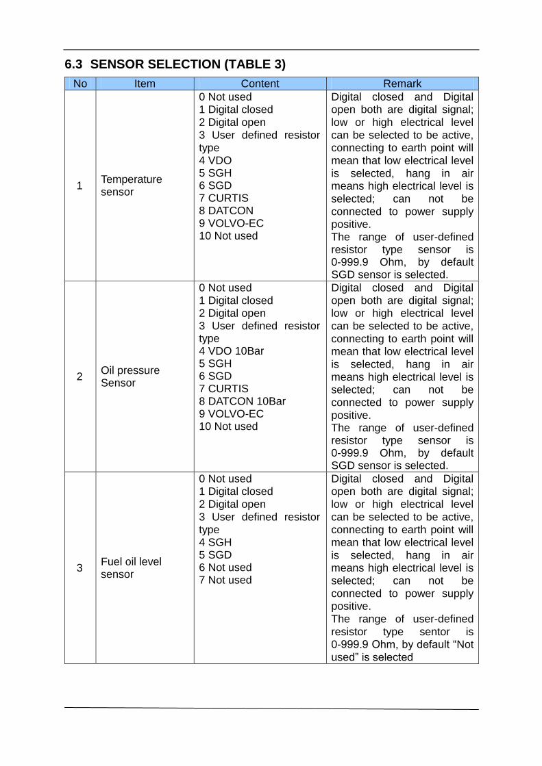
6.3 SENSOR SELECTION (TABLE 3)
No Item Content Remark
1 Temperature sensor
0 Not used 1 Digital closed 2 Digital open 3 User defined resistor type 4 VDO 5 SGH 6 SGD 7 CURTIS 8 DATCON 9 VOLVO-EC 10 Not used
Digital closed and Digital open both are digital signal; low or high electrical level can be selected to be active, connecting to earth point will mean that low electrical level is selected, hang in air means high electrical level is selected; can not be connected to power supply positive. The range of user-defined resistor type sensor is 0-999.9 Ohm, by defaultSGD sensor is selected.
2 Oil pressure Sensor
0 Not used 1 Digital closed 2 Digital open 3 User defined resistor type 4 VDO 10Bar 5 SGH 6 SGD 7 CURTIS 8 DATCON 10Bar 9 VOLVO-EC 10 Not used
Digital closed and Digital open both are digital signal; low or high electrical level can be selected to be active, connecting to earth point will mean that low electrical level is selected, hang in air means high electrical level is selected; can not be connected to power supply positive. The range of user-defined resistor type sensor is 0-999.9 Ohm, by defaultSGD sensor is selected.
3 Fuel oil level sensor
0 Not used 1 Digital closed 2 Digital open 3 User defined resistor type 4 SGH 5 SGD 6 Not used 7 Not used
Digital closed and Digital open both are digital signal; low or high electrical level can be selected to be active, connecting to earth point will mean that low electrical level
is selected, hang in air means high electrical level is selected; can not be connected to power supply positive. The range of user-defined resistor type sentor is 0-999.9 Ohm, by default “Notused” is selected
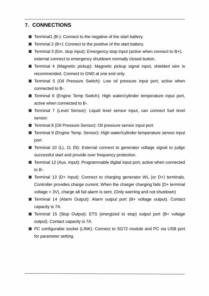
7. CONNECTIONS
◙ Terminal1 (B-): Connect to the negative of the start battery.
◙ Terminal 2 (B+): Connect to the positive of the start battery.
◙ Terminal 3 (Em. stop input): Emergency stop input (active when connect to B+),
external connect to emergency shutdown normally closed button.
◙ Terminal 4 (Magnetic pickup): Magnetic pickup signal input, shielded wire is
recommended. Connect to GND at one end only.
◙ Terminal 5 (Oil Pressure Switch): Low oil pressure input port, active when
connected to B-.
◙ Terminal 6 (Engine Temp Switch): High water/cylinder temperature input port,
active when connected to B-.
◙ Terminal 7 (Level Sensor): Liquid level sensor input, can connect fuel level
sensor.
◙ Terminal 8 (Oil Pressure Sensor): Oil pressure sensor input port.
◙ Terminal 9 (Engine Temp. Sensor): High water/cylinder temperature sensor input
port.
◙ Terminal 10 (L), 11 (N): External connect to generator voltage signal to judge
successful start and provide over frequency protection.
◙ Terminal 12 (Aux. Input): Programmable digital input port, active when connected
to B-.
◙ Terminal 13 (D+ Input): Connect to charging generator WL (or D+) terminals.
Controller provides charge current. When the charger charging fails (D+ terminal
voltage < 3V), charge alt fail alarm is sent. (Only warning and not shutdown)
◙ Terminal 14 (Alarm Output): Alarm output port (B+ voltage output). Contact
capacity is 7A.
◙ Terminal 15 (Stop Output): ETS (energized to stop) output port (B+ voltage
output). Contact capacity is 7A.
◙ PC configurable socket (LINK): Connect to SG72 module and PC via USB port
for parameter setting.
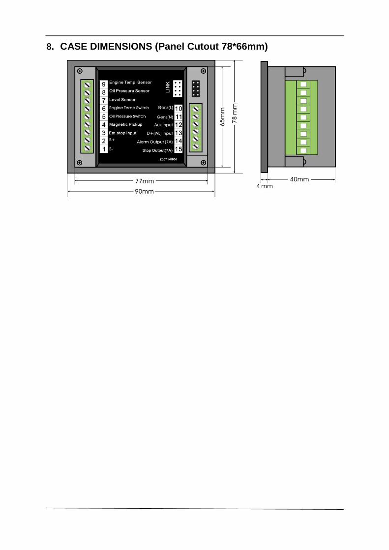
8. CASE DIMENSIONS (Panel Cutout 78*66mm)
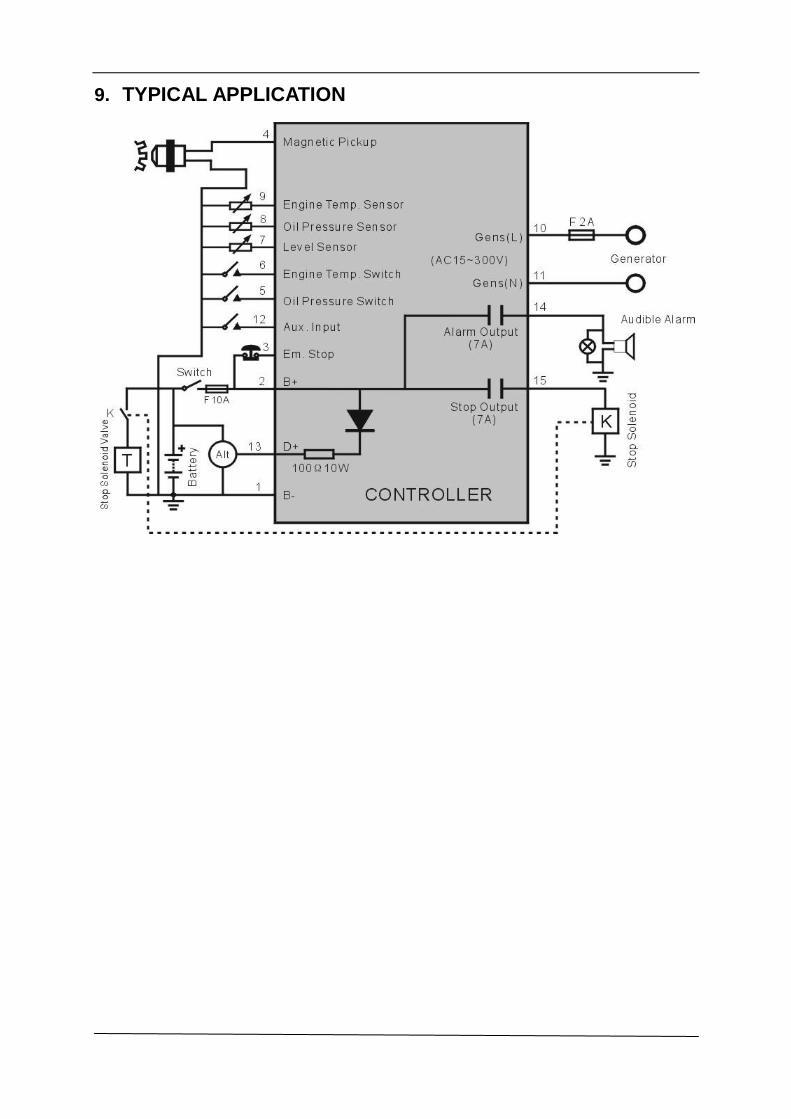
9. TYPICAL APPLICATION