Embed Size (px)
Citation preview
HLS300
POWER SHARE MODULE
USER MANUAL
SMARTGEN (ZHENGZHOU) TECHNOLOGY CO.,LTD.
Chinese trademark
English trademark
SmartGen — make your generator smart
SmartGen Technology Co., Ltd.
No.28 Jinsuo Road
Zhengzhou
Henan Province
P. R. China
Tel: 0086-(0)371-67988888/67981888
0086-(0)371-67991553/67992951
0086-(0)371-67981000(overseas)
Fax: 0086-(0)371-67992952
Web: www.smartgen.com.cn
www.smartgen.cn
Email: [email protected]
All rights reserved. No part of this publication may be reproduced in any material form (including
photocopying or storing in any medium by electronic means or other) without the written permission of
the copyright holder.
Applications for the copyright holder’s written permission to reproduce any part of this publication should
be addressed to SmartGen Technology at the address above.
Any reference to trademarked product names used within this publication is owned by their respective
companies.
SmartGen Technology reserves the right to change the contents of this document without prior notice.
Table 1 - Software Version
Date Version Content
2015-05-21 1.0 Original release.
2015-09-07 1.1 Modify terminal 1, terminal2 description.
2017-03-09 1.2 Add ―Power Regulation Limit‖ description in parameter setting item;
modified default values of Rated Voltage, Load Ramp Rate and etc.
2018-08-21 1.3
―Widely power supply range DC(8~35)V, suitable to different
starting battery voltage environment‖ changed as ―Widely power
supply range DC(8~35)V‖ in section 2.
2019-05-16 1.4 Changed lamp description and typical application diagram.
2019-11-26 2.0
1. Changed LOW-P, P<20, UNLOADING three output ports to
programmable output ports;
2. Added unbalance distribution of active power, P<20%, P>80%
threshold and delay settings;
3. Added potentiometer enable, unload input pulse enable, load
share optimization enable, speed regulator gain, unload failure and
Date Version Content
open enable, unload failure delay;
4. Added parameters of mutual exclusion about potentiometer: min.
pulse Tn of speed adjusting, cycle multiplier Tp of speed regulating,
active power range Xp of speed adjusting, frequency range Xf of
speed, active dead area △f of speed; when potentiometer is not
enabled, the parameters take effects;
5. Added Fault Findings part.
Table 2 – Symbolic Description
Sign Instruction
NOTE Highlights an essential element of a procedure to ensure correctness.
CAUTION! Indicates a procedure or practice, which, if not strictly observed, could result in
damage or destruction of equipment.
HLS300 POWER SHARE MODULE USER MANUAL
HLS300 Power Share Module Version 2.0 2019-11-26 Page 4 of 17
CONTENT
1 OVERVIEW .............................................................................................................................................. 5
2 PERFORMANCE AND CHARACTERISTICS ......................................................................................... 5
3 SPECIFICATION ...................................................................................................................................... 5
4 PANEL INDICATORS AND TERMINALS DESCRIPTION ...................................................................... 6
5 SCOPES AND DEFINITIONS OF PROGRAMMABLE PARAMETERS ............................................... 10
6 OUTPUT CONFIGURATION CONTENTS ............................................................................................ 13
7 FUNCTION DESCRIPTION ................................................................................................................... 14
7.1 INSTRUCTION .......................................................................................................................... 14
7.2 FIXED POWER MODE ............................................................................................................. 14
7.3 POWER SHARE MODE ........................................................................................................... 14
7.4 TEST MODE ............................................................................................................................. 14
8 TYPICAL DIAGRAM .............................................................................................................................. 15
9 CASE DIMENSION ................................................................................................................................ 16
10 INSTALLATION PRECAUTIONS ........................................................................................................... 17
10.1 OUTPUT AND EXPAND RELAYS ............................................................................................ 17
10.2 AC INPUT .................................................................................................................................. 17
10.3 WITHSTAND VOLTAGE TEST ................................................................................................. 17
11 FAULT FINDING .................................................................................................................................... 17
HLS300 POWER SHARE MODULE USER MANUAL
HLS300 Power Share Module Version 2.0 2019-11-26 Page 5 of 17
1 OVERVIEW
HLS300 Power Share Module is a special design for genset power share. On the basis of the set
parameters, the module conducts automatically power share in genset running process.
The main function of HLS300 module is to share active load to each operating genset according to
genset capacitance. The module is brief to operate, easy to install and widely used for ship genset and
land genset.
2 PERFORMANCE AND CHARACTERISTICS
Main characters are as below:
Suitable for 3-phase 3-wire, single phase 2-wire systems with frequency 50/60/Hz;
Adjustable potentiometer allows for setting main parameters of power share.
Module parameters can be set via upper computer test software. LINK port should be connected to
upper computer via SG72 module (USB to LINK)
8 relay outputs, 2 of which are used for controlling INCR. speed raise, and DECR. reduce, 5 are used
for -P, UNLOADING, P>80%, P<20%, LOW-P output, and 1 is used for C/B OPEN;
1 FIXLOAD mode, 1 UNL, 1 close and 1 60Hz optional digital input;
One test button for testing relay output and panel indicators;
Wide power supply range DC(8~35)V;
35mm guide rail mounting;
Modular design, pluggable terminal, compact structure with easy installation.
3 SPECIFICATION
Table 3 – Product Parameters
Parameter Details
Working Voltage DC8.0V to 35.0V continuous
Overall Consumption ≤2W(Standby mode≤0.5W)
AC Input AC50V~ AC620 V (ph-ph)
AC Frequency 50Hz/60Hz
Relay Output 7A AC250V Volt free output
Case Dimensions 161.6mm x 89.7mm x 60.7mm
CT Secondary Current Rated: 5A
Working Conditions Temperature: (-25~+70)°C Humidity: (20~95)%
Storage Conditions Temperature: (-25~+70)°C
Insulation Intensity Apply AC2.2kV voltage between high voltage terminal and low voltage
terminal; The leakage current is not more than 3mA within 1min.
Weight 0.45kg
HLS300 POWER SHARE MODULE USER MANUAL
HLS300 Power Share Module Version 2.0 2019-11-26 Page 6 of 17
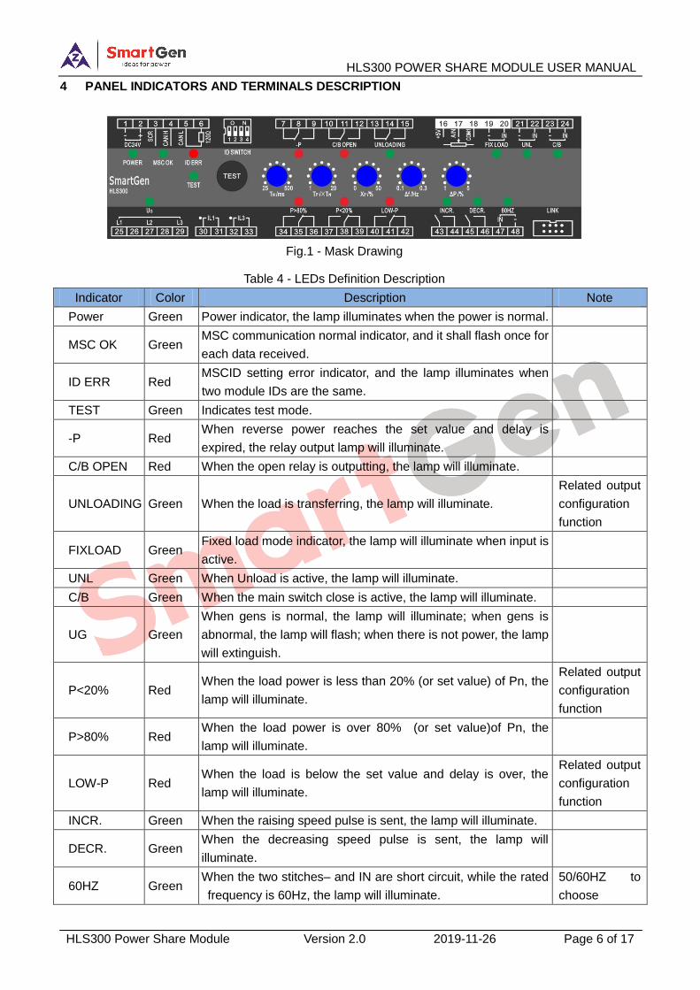
4 PANEL INDICATORS AND TERMINALS DESCRIPTION
Fig.1 - Mask Drawing
Table 4 - LEDs Definition Description
Indicator Color Description Note
Power Green Power indicator, the lamp illuminates when the power is normal.
MSC OK Green MSC communication normal indicator, and it shall flash once for
each data received.
ID ERR Red MSCID setting error indicator, and the lamp illuminates when
two module IDs are the same.
TEST Green Indicates test mode.
-P Red When reverse power reaches the set value and delay is
expired, the relay output lamp will illuminate.
C/B OPEN Red When the open relay is outputting, the lamp will illuminate.
UNLOADING Green When the load is transferring, the lamp will illuminate.
Related output
configuration
function
FIXLOAD Green Fixed load mode indicator, the lamp will illuminate when input is
active.
UNL Green When Unload is active, the lamp will illuminate.
C/B Green When the main switch close is active, the lamp will illuminate.
UG Green
When gens is normal, the lamp will illuminate; when gens is
abnormal, the lamp will flash; when there is not power, the lamp
will extinguish.
P<20% Red When the load power is less than 20% (or set value) of Pn, the
lamp will illuminate.
Related output
configuration
function
P>80% Red When the load power is over 80% (or set value)of Pn, the
lamp will illuminate.
LOW-P Red When the load is below the set value and delay is over, the
lamp will illuminate.
Related output
configuration
function
INCR. Green When the raising speed pulse is sent, the lamp will illuminate.
DECR. Green When the decreasing speed pulse is sent, the lamp will
illuminate.
60HZ Green When the two stitches– and IN are short circuit, while the rated
frequency is 60Hz, the lamp will illuminate.
50/60HZ to
choose
HLS300 POWER SHARE MODULE USER MANUAL
HLS300 Power Share Module Version 2.0 2019-11-26 Page 7 of 17
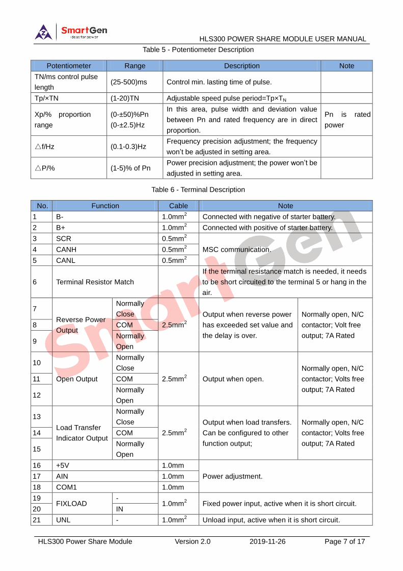
Table 5 - Potentiometer Description
Potentiometer Range Description Note
TN/ms control pulse
length (25-500)ms Control min. lasting time of pulse.
Tp/×TN (1-20)TN Adjustable speed pulse period=Tp×TN
Xp/% proportion
range
(0-±50)%Pn
(0-±2.5)Hz
In this area, pulse width and deviation value
between Pn and rated frequency are in direct
proportion.
Pn is rated
power
△f/Hz (0.1-0.3)Hz Frequency precision adjustment; the frequency
won’t be adjusted in setting area.
△P/% (1-5)% of Pn Power precision adjustment; the power won’t be
adjusted in setting area.
Table 6 - Terminal Description
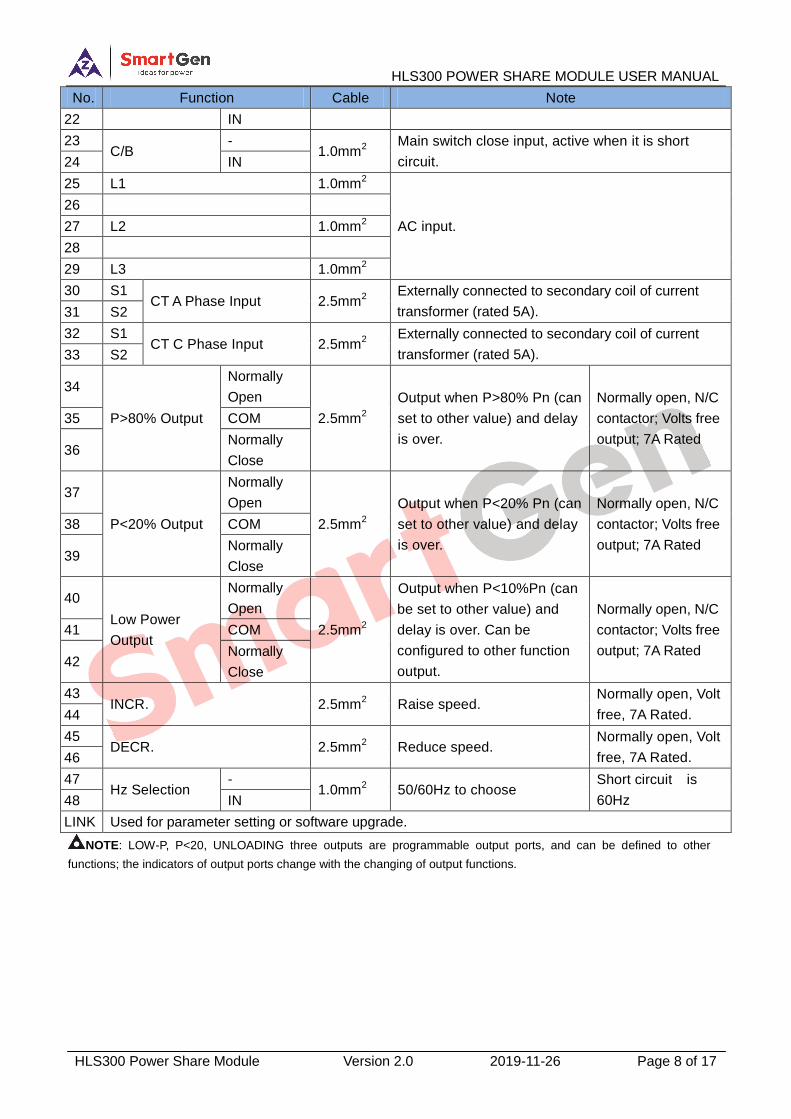
No. Function Cable Note
1 B- 1.0mm2 Connected with negative of starter battery.
2 B+ 1.0mm2 Connected with positive of starter battery.
3 SCR 0.5mm2
MSC communication. 4 CANH 0.5mm2
5 CANL 0.5mm2
6 Terminal Resistor Match
If the terminal resistance match is needed, it needs
to be short circuited to the terminal 5 or hang in the
air.
7
Reverse Power
Output
Normally
Close
2.5mm2
Output when reverse power
has exceeded set value and
the delay is over.
Normally open, N/C
contactor; Volt free
output; 7A Rated
8 COM
9 Normally
Open
10
Open Output
Normally
Close
2.5mm2 Output when open.
Normally open, N/C
contactor; Volts free
output; 7A Rated
11 COM
12 Normally
Open
13
Load Transfer
Indicator Output
Normally
Close
2.5mm2
Output when load transfers.
Can be configured to other
function output;
Normally open, N/C
contactor; Volts free
output; 7A Rated
14 COM
15 Normally
Open
16 +5V 1.0mm
Power adjustment. 17 AIN 1.0mm
18 COM1 1.0mm
19 FIXLOAD
- 1.0mm
2 Fixed power input, active when it is short circuit.
20 IN
21 UNL - 1.0mm2 Unload input, active when it is short circuit.
HLS300 POWER SHARE MODULE USER MANUAL
HLS300 Power Share Module Version 2.0 2019-11-26 Page 8 of 17
No. Function Cable Note
22 IN
23 C/B
- 1.0mm
2
Main switch close input, active when it is short
circuit. 24 IN
25 L1 1.0mm2
AC input.
26
27 L2 1.0mm2
28
29 L3 1.0mm2
30 S1 CT A Phase Input 2.5mm
2
Externally connected to secondary coil of current
transformer (rated 5A). 31 S2
32 S1 CT C Phase Input 2.5mm
2
Externally connected to secondary coil of current
transformer (rated 5A). 33 S2
34
P>80% Output
Normally
Open
2.5mm2
Output when P>80% Pn (can
set to other value) and delay
is over.
Normally open, N/C
contactor; Volts free
output; 7A Rated
35 COM
36 Normally
Close
37
P<20% Output
Normally
Open
2.5mm2
Output when P<20% Pn (can
set to other value) and delay
is over.
Normally open, N/C
contactor; Volts free
output; 7A Rated
38 COM
39 Normally
Close
40
Low Power
Output
Normally
Open
2.5mm2
Output when P<10%Pn (can
be set to other value) and
delay is over. Can be
configured to other function
output.
Normally open, N/C
contactor; Volts free
output; 7A Rated
41 COM
42 Normally
Close
43 INCR. 2.5mm
2 Raise speed.
Normally open, Volt
free, 7A Rated. 44
45 DECR. 2.5mm
2 Reduce speed.
Normally open, Volt
free, 7A Rated. 46
47 Hz Selection
- 1.0mm
2 50/60Hz to choose
Short circuit is
60Hz 48 IN
LINK Used for parameter setting or software upgrade.
NOTE: LOW-P, P<20, UNLOADING three outputs are programmable output ports, and can be defined to other
functions; the indicators of output ports change with the changing of output functions.
HLS300 POWER SHARE MODULE USER MANUAL
HLS300 Power Share Module Version 2.0 2019-11-26 Page 9 of 17
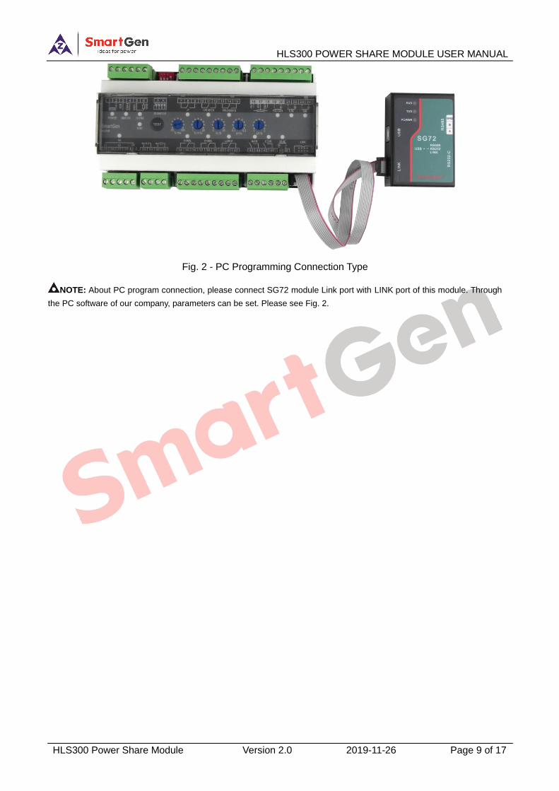
Fig. 2 - PC Programming Connection Type
NOTE: About PC program connection, please connect SG72 module Link port with LINK port of this module. Through
the PC software of our company, parameters can be set. Please see Fig. 2.
HLS300 POWER SHARE MODULE USER MANUAL
HLS300 Power Share Module Version 2.0 2019-11-26 Page 10 of 17
5 SCOPES AND DEFINITIONS OF PROGRAMMABLE PARAMETERS
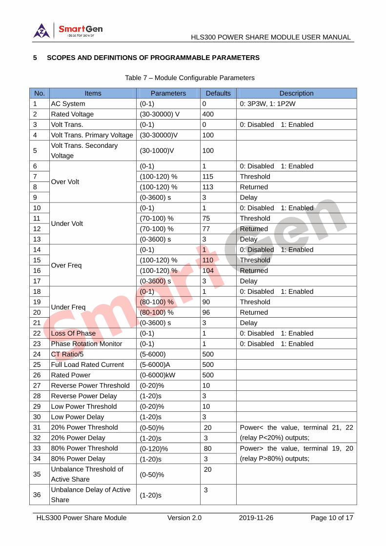
Table 7 – Module Configurable Parameters
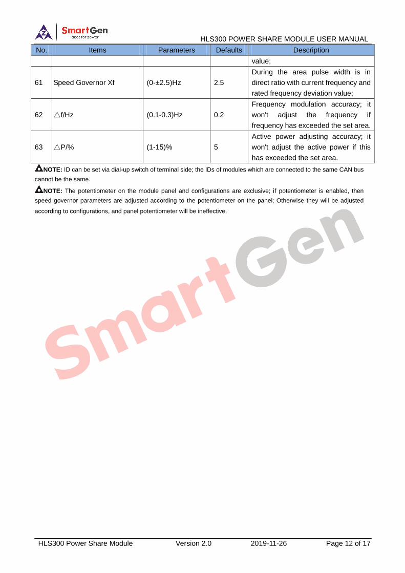
No. Items Parameters Defaults Description
1 AC System (0-1) 0 0: 3P3W, 1: 1P2W
2 Rated Voltage (30-30000) V 400
3 Volt Trans. (0-1) 0 0: Disabled 1: Enabled
4 Volt Trans. Primary Voltage (30-30000)V 100
5 Volt Trans. Secondary
Voltage (30-1000)V 100
6
Over Volt
(0-1) 1 0: Disabled 1: Enabled
7 (100-120) % 115 Threshold
8 (100-120) % 113 Returned
9 (0-3600) s 3 Delay
10
Under Volt
(0-1) 1 0: Disabled 1: Enabled
11 (70-100) % 75 Threshold
12 (70-100) % 77 Returned
13 (0-3600) s 3 Delay
14
Over Freq
(0-1) 1 0: Disabled 1: Enabled
15 (100-120) % 110 Threshold
16 (100-120) % 104 Returned
17 (0-3600) s 3 Delay
18
Under Freq
(0-1) 1 0: Disabled 1: Enabled
19 (80-100) % 90 Threshold
20 (80-100) % 96 Returned
21 (0-3600) s 3 Delay
22 Loss Of Phase (0-1) 1 0: Disabled 1: Enabled
23 Phase Rotation Monitor (0-1) 1 0: Disabled 1: Enabled
24 CT Ratio/5 (5-6000) 500
25 Full Load Rated Current (5-6000)A 500
26 Rated Power (0-6000)kW 500
27 Reverse Power Threshold (0-20)% 10
28 Reverse Power Delay (1-20)s 3
29 Low Power Threshold (0-20)% 10
30 Low Power Delay (1-20)s 3
31 20% Power Threshold (0-50)% 20 Power< the value, terminal 21, 22
(relay P<20%) outputs; 32 20% Power Delay (1-20)s 3
33 80% Power Threshold (0-120)% 80 Power> the value, terminal 19, 20
(relay P>80%) outputs; 34 80% Power Delay (1-20)s 3
35 Unbalance Threshold of
Active Share (0-50)%
20
36 Unbalance Delay of Active
Share (1-20)s
3
HLS300 POWER SHARE MODULE USER MANUAL
HLS300 Power Share Module Version 2.0 2019-11-26 Page 11 of 17
No. Items Parameters Defaults Description
37 LOW-P Output Type (0-1) 0 0: N/O output 1: N/C output
38 LOW-P Output Contents
(0-30) 16 Default: LOW-P output
Please refer to Output Port Contents.
39 P<20% Output Type (0-1) 0 0: N/O output 1: N/C output
40 P<20% Output Contents
(0-30) 15 Default: P<20% output
Please refer to Output Port Contents.
41 UNLOADING Output Type (0-1) 0 0: N/O output 1: N/C output
42 UNLOADING Output
Contents (0-30)
12 Default: UNLOADING output;
Please refer to Output Port Contents.
43 Address (1-254) 1
44 Load Ramp Rate (0-100)% 2
45 Load Ramp Rate Delay
Percentage (1-40)% 15
46 Load Ramp Rate Delay (0-30)s 5
47 Load Parallel Ramp
Minimum (0-100)% 5
Load value of unload and breaker
open;
48 Load Feedback Percentage (0-100)% 50 Percentage of frequency dividing
speed output;
49 Open Pulse Output (1-1000)s 3
50 Average Beat Freq (0-1) 1 0: Disabled 1: Enabled
51 Power Regulation Limit (0-50)% 30
When the max. output duty ratio of
raise/drop speed relay is 0, the relay
does not output.
52 Unload Input Pulse Enable (0-1) 1
There is no need to issue signal
continuously during the unload
process if this is enabled.
53 Load Share Optimization
Enable (0-1) 1
Adjust to optimize in dead area
margin; suitable for high flexibility
occasions for governor.
54 Speed Regulating Gain (0-1000) 100 Adjust the proportion gain of governor
gain.
55 Failed to Unload and Open
Enable (0-1) 1 0: Disable 1: Enable
56 Failed to Unload Delay (0-3600)s 30
During the delay, if unload is not up to
the target, unload failure alarm
occurs; if breaker open enable is set,
then it will open.
57 Potentiometer Enable (0-1) 1 0: Disable 1: Enable
58 Speed Governor Tn (25-500)ms 100 The min. lasting time of speed control
pulse;
59 Speed Govenor Tp (1-200) 20 Speed pulse period=TpxTN;
60 Speed Governor Xp (0-±50)% 50
During the area pulse width is in
direct ratio with current active power
and rated active power deviation
HLS300 POWER SHARE MODULE USER MANUAL
HLS300 Power Share Module Version 2.0 2019-11-26 Page 12 of 17
No. Items Parameters Defaults Description
value;
61 Speed Governor Xf (0-±2.5)Hz 2.5
During the area pulse width is in
direct ratio with current frequency and
rated frequency deviation value;
62 △f/Hz (0.1-0.3)Hz 0.2
Frequency modulation accuracy; it
won't adjust the frequency if
frequency has exceeded the set area.
63 △P/% (1-15)% 5
Active power adjusting accuracy; it
won't adjust the active power if this
has exceeded the set area.
NOTE: ID can be set via dial-up switch of terminal side; the IDs of modules which are connected to the same CAN bus
cannot be the same.
NOTE: The potentiometer on the module panel and configurations are exclusive; if potentiometer is enabled, then
speed governor parameters are adjusted according to the potentiometer on the panel; Otherwise they will be adjusted
according to configurations, and panel potentiometer will be ineffective.
HLS300 POWER SHARE MODULE USER MANUAL
HLS300 Power Share Module Version 2.0 2019-11-26 Page 13 of 17
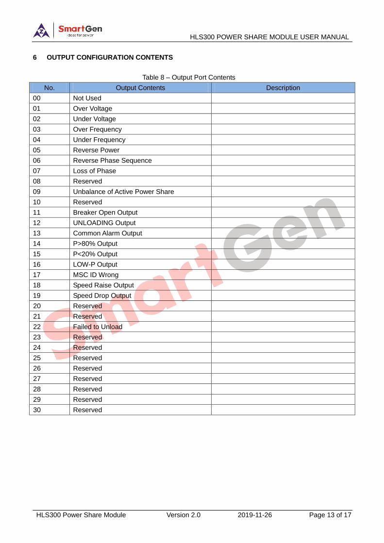
6 OUTPUT CONFIGURATION CONTENTS
Table 8 – Output Port Contents
No. Output Contents Description
00 Not Used
01 Over Voltage
02 Under Voltage
03 Over Frequency
04 Under Frequency
05 Reverse Power
06 Reverse Phase Sequence
07 Loss of Phase
08 Reserved
09 Unbalance of Active Power Share
10 Reserved
11 Breaker Open Output
12 UNLOADING Output
13 Common Alarm Output
14 P>80% Output
15 P<20% Output
16 LOW-P Output
17 MSC ID Wrong
18 Speed Raise Output
19 Speed Drop Output
20 Reserved
21 Reserved
22 Failed to Unload
23 Reserved
24 Reserved
25 Reserved
26 Reserved
27 Reserved
28 Reserved
29 Reserved
30 Reserved
HLS300 POWER SHARE MODULE USER MANUAL
HLS300 Power Share Module Version 2.0 2019-11-26 Page 14 of 17
7 FUNCTION DESCRIPTION
7.1 INSTRUCTION
The function of HLS300 Power Share Module is to proportionally share active load to each
operating genset according to genset capacitance. When ―FIXLOAD‖ is active, the module works in
fixed power mode; otherwise the module works in power share mode. Press button for 3s, and
it will enter into test mode, which is used to test relay output and indicator status.
7.2 FIXED POWER MODE
Target power can be set via the external device connected with terminal 16, 17, 18. When close
input is active, the module will adjust present power to target power and stabilize it between △f and
△P.
7.3 POWER SHARE MODE
Multiple modules are connected with each other via CAN bus and operate in power share mode
together. Target power is an average of present power sums of these modules. When close input is
active, the module will adjust present power to target power and stabilize it between △f and △P.
7.4 TEST MODE
Press button for 3s, and the module will enter into test mode and the lamp will illuminate, in the
mean time the other lamps irrelevant with relay output will illuminate. -P relay outputs and the
corresponding lamp will illuminate. In this mode, for every time to press button, there will be a
relay output and the corresponding lamp will illuminate. The module will quit test mode after relay
output is finished (every time there will be only one relay output and the corresponding lamp will
illuminate). When it is in test mode, the module will automatically quit if there is no button pressed for
about 18s.
NOTE: Test mode is prohibited when the module is operating (when close input is active).
HLS300 POWER SHARE MODULE USER MANUAL
HLS300 Power Share Module Version 2.0 2019-11-26 Page 15 of 17
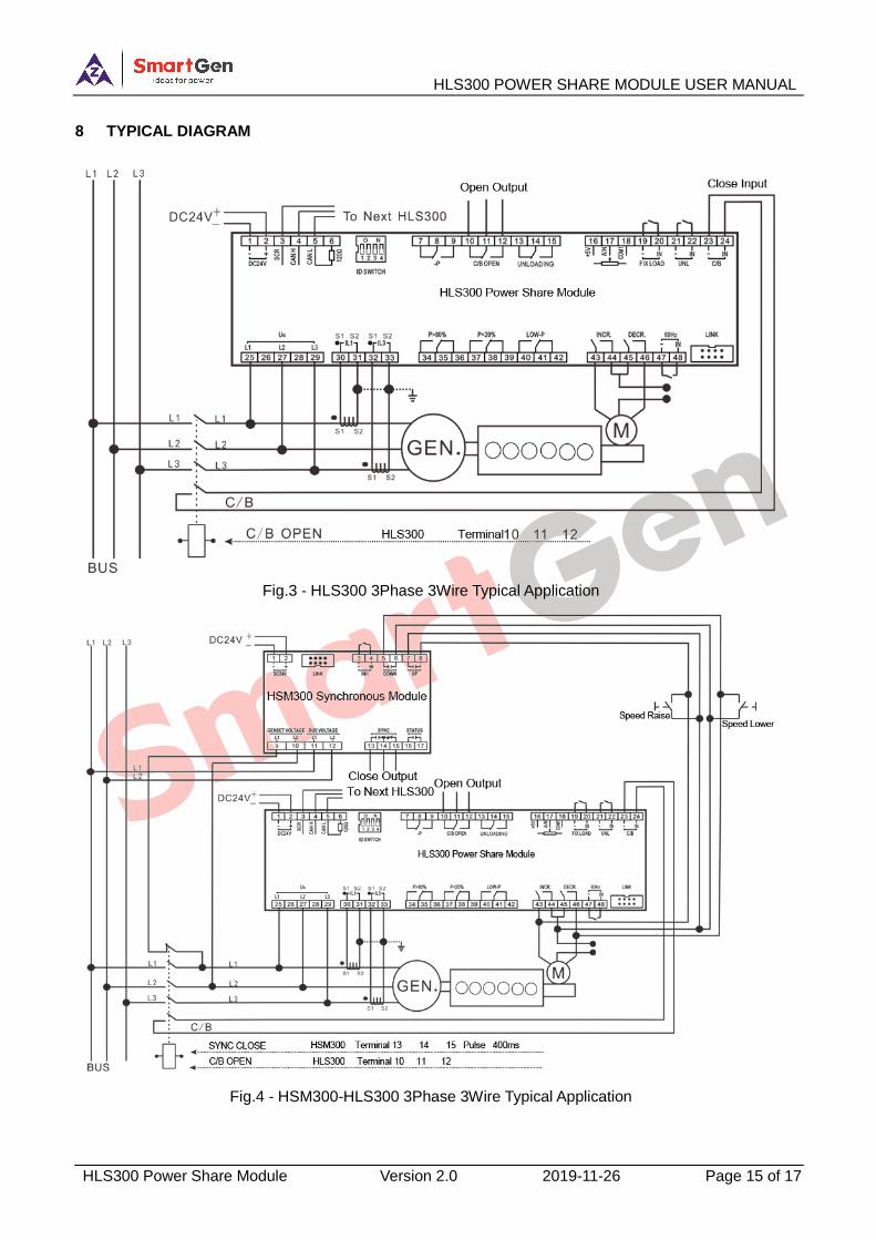
8 TYPICAL DIAGRAM
Fig.3 - HLS300 3Phase 3Wire Typical Application
Fig.4 - HSM300-HLS300 3Phase 3Wire Typical Application
HLS300 POWER SHARE MODULE USER MANUAL
HLS300 Power Share Module Version 2.0 2019-11-26 Page 16 of 17
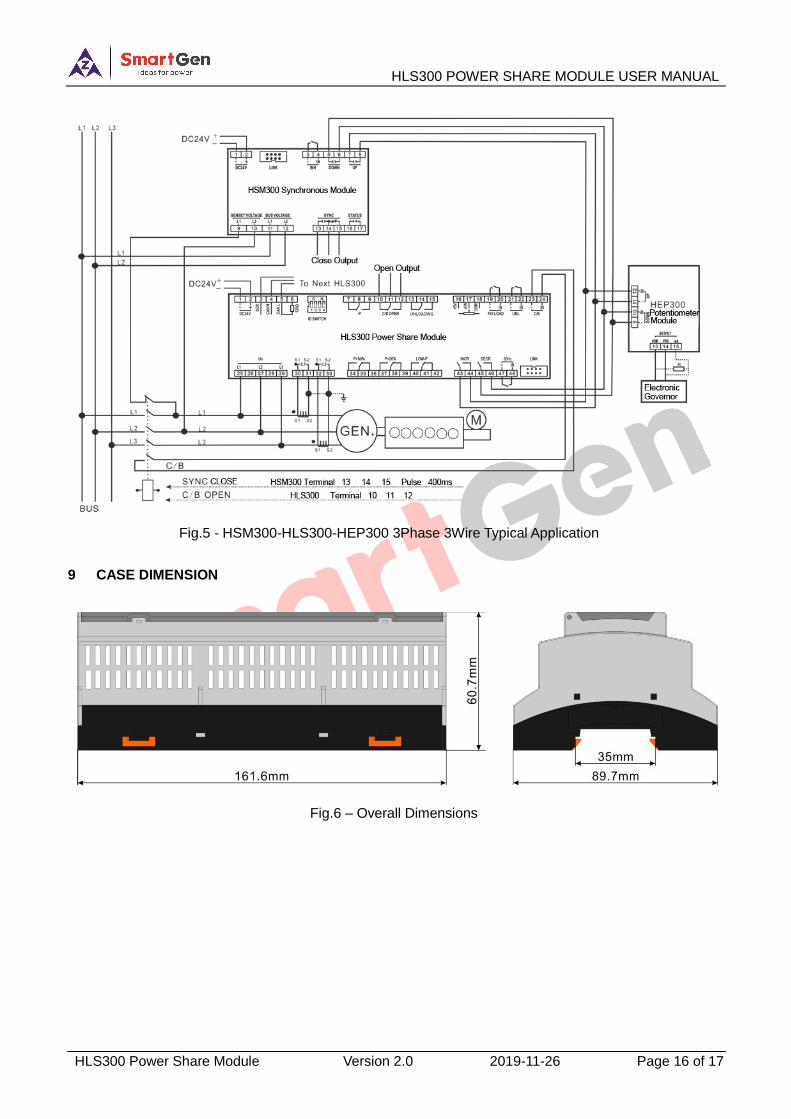
Fig.5 - HSM300-HLS300-HEP300 3Phase 3Wire Typical Application
9 CASE DIMENSION
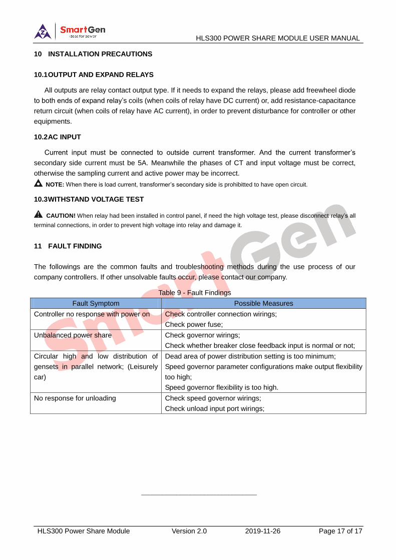
Fig.6 – Overall Dimensions
HLS300 POWER SHARE MODULE USER MANUAL
HLS300 Power Share Module Version 2.0 2019-11-26 Page 17 of 17
10 INSTALLATION PRECAUTIONS
10.1 OUTPUT AND EXPAND RELAYS
All outputs are relay contact output type. If it needs to expand the relays, please add freewheel diode
to both ends of expand relay’s coils (when coils of relay have DC current) or, add resistance-capacitance
return circuit (when coils of relay have AC current), in order to prevent disturbance for controller or other
equipments.
10.2 AC INPUT
Current input must be connected to outside current transformer. And the current transformer’s
secondary side current must be 5A. Meanwhile the phases of CT and input voltage must be correct,
otherwise the sampling current and active power may be incorrect.
NOTE: When there is load current, transformer’s secondary side is prohibitted to have open circuit.
10.3 WITHSTAND VOLTAGE TEST
CAUTION! When relay had been installed in control panel, if need the high voltage test, please disconnect relay’s all
terminal connections, in order to prevent high voltage into relay and damage it.
11 FAULT FINDING
The followings are the common faults and troubleshooting methods during the use process of our
company controllers. If other unsolvable faults occur, please contact our company.
Table 9 - Fault Findings
Fault Symptom Possible Measures
Controller no response with power on Check controller connection wirings;
Check power fuse;
Unbalanced power share Check governor wirings;
Check whether breaker close feedback input is normal or not;
Circular high and low distribution of
gensets in parallel network; (Leisurely
car)
Dead area of power distribution setting is too minimum;
Speed governor parameter configurations make output flexibility
too high;
Speed governor flexibility is too high.
No response for unloading Check speed governor wirings;
Check unload input port wirings;
_________________________________