Embed Size (px)
Citation preview
資料 22-8-2 移動容器規格委員会
R1.8.6.
1
高圧ガス容器バルブ設計・製造基準 KHKS0124 改正案(技術基準比較表)
改正案(KHKS0124(20××)) 現行(KHKS0124(2014)) ISO10297(2014) 備考
1 総則 1.1 適用範囲 この高圧ガス容器バルブ設計・製造基準(以下「基準」とい
う。)は、圧縮ガス、液化ガス又は圧縮アセチレンガスを充塡
する容器に装着されるバルブの設計、製造及び試験に適用す
る。ただし、次の a)から d)までのいずれかに該当するものにつ
いては、この限りでない。
a) 鋳物製のバルブ
b) 超低温容器、消火器用容器、呼吸器用容器(医療の用に供
するものを除く。)及び液化石油ガス用容器に装着される
バルブ
c) バルブに装着される減圧装置、残圧保持装置、逆止装置及
び安全弁
d) ボールバルブ及びクイックリリースバルブ
1 総則 1.1 適用範囲 この高圧ガス容器バルブ設計・製造基準(以下「基準」とい
う。)は、圧縮ガス、液化ガス又は圧縮アセチレンガスを充て
んする容器に装着されるバルブの設計、製造及び試験に適用す
る。ただし、次の a)から c)までのいずれかに該当するものにつ
いては、この限りでない。
a) 鋳物製のバルブ
b) 超低温容器、消火器用容器、呼吸器用容器(医療の用に供
するものを除く。)及び液化石油ガス用容器に装着されるバ
ルブ
c) バルブに装着される減圧装置、残圧保持装置、逆止装置及
び安全弁
1 scope This International Standard specifies design, type testing and marking requirements for: a) cylinder valves intended to be fitted to refillabletransportable gas cylinders;b) main valves (excluding ball valves) for cylinderbundles; c) cylinder valves or main valves with integratedpressure regulator (VIPR);which convey compressed, liquefied or dissolved gases.NOTE 1 Where there is no risk of ambiguity, cylindervalves, main valves and VIPR are addressed with thecollective term “valves” within this InternationalStandard.This International Standard covers the function of avalve as a closure.This International Standard does not apply to— valves for cryogenic equipment, portable fire extinguishers and liquefied petroleum gas (LPG), and — quick-release valves (e.g. for fire-extinguishing, explosion protection and rescue applications), nonreturn valves or ball valves. NOTE 2 Requirements for valves for cryogenic vessels are specified in ISO 21011 and at a regional level e.g. in EN 1626. Requirements for LPG valves are specified in ISO 14245 or ISO 15995. Requirements for quick-release valves are specified e.g. in ISO 17871. Requirements for valves for portable fire extinguishers at a regional level are specified e.g. in EN 3 series. Requirements for non-return valves and ball valves might be specified in international/regional standards. NOTE 3 Requirements for manufacturing tests and examinations of valves covered by this International
1.1 適用範囲
d) ISO10297(2014)(以
下、「ISO」という。)に
おいて、ボールバルブ、
クイックリリースバルブ
は適用除外であり、整合
させるため適用除外とし
た。案
2
改正案(KHKS0124(20××)) 現行(KHKS0124(2014)) ISO10297(2014) 備考
Standard are given in ISO 14246. NOTE 4 Additional requirements for VIPR are specified in ISO 22435 for industrial applications or ISO 10524-3 for medical applications. Additional requirements for residual pressure valves with or without a non-return function are specified in ISO 15996. Additional requirements for pressure-relief devices might be specified in international/regional regulations/standards. NOTE 5 Additional specific requirements for valves for breathing apparatus at a regional level are specified e.g. in EN 144 series. Additional specific requirements for quick-release valves for fixed fire-fighting systems are specified in ISO 16003 and at a regional level e.g. in EN 12094–4.
1.2 引用規格 次に掲げる規格は、この基準に引用されることによって、こ
の基準の規定の一部を構成する。 JIS B 8241(1996)「継目なし鋼製高圧ガス容器」 JIS B 8246(2004)「高圧ガス容器用弁」 ISO 148-1(2016)「Metallic materials - Charpy pendulum impact test - Part 1: Test method」 ISO 407(2004)「Small medical gas cylinders - Pin-index yoke-type valve connections;Technical Corrigendum 1」 ISO 5145(2017)「Gas cylinders -- Cylinder valve outlets for gases and gas mixtures -- Selection and dimensioning」 ISO 10156(2017)「Gas cylinders -- Gases and gas mixtures -- Determination of fire potential and oxidizing ability for the selection of cylinder valve outlets」 ISO 10692-1(2001)「Gas cylinders - Gas cylinder valve connections for use in microelectronic industry - Part1 : Outlet connection」 ISO 11114-1(2017)「Gas cylinders - Compatibility of cylinder
1.2 引用規格 次に掲げる規格は、この基準に引用されることによって、こ
の基準の規定の一部を構成する。 JIS B 8241(1996)「継目なし鋼製高圧ガス容器」 JIS B 8246(2004)「高圧ガス容器用弁」 ISO 407(2004)「Small medical gas cylinders - Pin-index yoke-type valve connections;Technical Corrigendum 1」 ISO 5145(2008)「Cylinder valve outlets for gases and gas mixtures; selection and dimensioning」 ISO 10156(2010)「Gases and mixtures - Determination of fire potential and oxidizing ability for the selection of cylinder valve outlets」 ISO 10692-1(2001)「Gas cylinders - Gas cylinder valve connections for use in microelectronic industry - Part1 : Outlet connection」 ISO 10920(1997)「Gas cylinders - 25E taper thread for connection of valves to gascylinders - art1 :Specifications」 ISO 11114-1(2012)「Gas cylinders - Compatibility of cylinder
2 Normative references The following referenced documents, in whole or in part, are normatively referenced in this document and are indispensable for its application. For dated references, only the edition cited applies. For undated references, the latest edition of the referenced document (including any amendments) applies. ISO 148-1, Metallic materials — Charpy pendulum impact test — Part 1: Test method ISO 407, Small medical gas cylinders — Pin-index yoke-type valve connections ISO 10286, Gas cylinders — Terminology ISO 10524-3, Pressure regulators for use with medical gases — Part 3: Pressure regulators integrated with cylinder valves ISO 11114-1, Gas cylinders — Compatibility of cylinder and valve materials with gas contents — Part 1: Metallic materials ISO 11114-2, Gas cylinders — Compatibility of cylinder and valve materials with gas contents — Part 2:
1.2 引用規格 KHKS0124 ( 以 下 、
「KHKS」という。)の規
定に必要な規格のみ採用
した。 引用規格については、資
料 22-8-3 を参照。 案
3
改正案(KHKS0124(20××)) 現行(KHKS0124(2014)) ISO10297(2014) 備考
and valve materials with gas contents - Part 1 :Metallic materials」 ISO 11114-2(2013)「Gas cylinders - Compatibility of cylinder and valve materials with gas contents - Part 2 :Non - Metallic materials」 ISO 11117(2008)「Gas cylinders - Valve protection caps and valve guards for industrial and medical gas cylinders - Design, construction and tests」 ISO 11363-1(2018)「Gas cylinders - 17E and 25E taper threads for connection of valves to gas cylinders - Part 1: Specifications」 ISO 13341(2015)「Gas cylinders - Fitting of valves to gas cylinders」 ISO 15001(2010)「Anaesthetic and respiratory equipment - Compatibility with oxygen」 ISO 15245-1(2013)「Gas cylinders - Parallel threads for connection of valves to gas cylinders - Part 1: Specification」 ISO21010(2004) 「 Cryogenic vessels - Gas/material compatibility」
and valve materials with gas contents : Part 1 :Metallic materials」 ISO 11114-2(2013)「Gas cylinders - Compatibility of cylinder and valve materials with gas contents : Part 2 :Non - Metallic materials」 ISO 11116-1(1999)「Gas cylinders - 17E taper thread for connection of valves to gas cylinders - Specification」 ISO 11117(2008)「Gas cylinders - Valve protection caps and valve guards for industrial and medical gas cylinders - Design, construction and tests」 ISO 13341(1997)「Transportable gas cylinders - Fitting of valves to gas cylinders」 ISO 15001(2010)「Anaesthetic and respiratory equipment - Compatibility with oxygen 」 ISO 15245(2001) 「 Gas cylinders - Parallel threads - Specificaiton」ction of valves to gas cylinders - Specification」
Non-metallic materials ISO 11117:2008, Gas cylinders — Valve protection caps and valve guards — Design, construction and tests ISO 13341, Gas cylinders — Fitting of valves to gas cylinders ISO 15615:2013, Gas welding equipment — Acetylene manifold systems for welding, cutting and allied processes — Safety requirements in high-pressure devices ISO 15996, Gas cylinders — Residual pressure valves — General requirements and type testing ISO 22435, Gas cylinders — Cylinder valves with integrated pressure regulators — Specification and type Testing
1.3 用語の定義 1.3.1 一般 この基準において使用する用語の意義は、高圧ガス保安法、
容器保安規則(昭和 41 年 5 月 25 日通商産業省令第 50 号)及
び容器保安規則の機能性基準の運用について(20190606 保局
第 7 号)による他、次の 1.3.2 から 1.3.11 までに掲げる用語に
ついては当該 1.3.2 から 1.3.11 までに定めるところによる。 1.3.2 バルブ試験圧力 圧縮ガス(圧縮アセチレンガスを除く。)にあっては、 高
充塡圧力に 1.2 を乗じた圧力、液化ガスにあっては容器保安規
則第 2 条第 26 号又は第 28 号に定める耐圧試験圧力、溶栓式安
全弁を装着している容器に充塡される圧縮アセチレンガスに
1.3 用語の定義 1.3.1 一般 この基準において使用する用語の意義は、高圧ガス保安法、
容器保安規則(昭和 41 年 5 月 25 日通商産業省令第 50 号)
及び容器保安規則の機能性基準の運用について(平成13・03・09 原院第 5 号)による他、次の 1.3.2 から 1.3.11 までに掲げる
用語については当該 1.3.2 から 1.3.11 までに定めるところに
よる。 1.3.2 バルブ試験圧力 圧縮ガス(圧縮アセチレンガスを除く。)にあっては、 高
充てん圧力に 1.2 を乗じた圧力、液化ガスにあっては容器保安
規則第 2 条第 26 号又は第 28 号に定める耐圧試験圧力、溶栓
式安全弁を装着している容器に充てんされる圧縮アセチレン
3 Terms, definitions and symbols For the purposes of this document, the terms and definitions given in ISO 10286, and the following apply. 3.1 valve operating mechanism mechanism which closes and opens the valve orifice and which includes the internal and external sealing systems Note 1 to entry: In ISO 22435 the valve operating mechanism is called shut-off mechanism. Note 2 to entry: For some VIPR designs the pressure regulating valve can act as the shut-off mechanism. EXAMPLE A threaded valve spindle which, when rotated, raises and lowers a seal/seat. 3.2 valve design
1.3 用語の定義 KHKS に新たに規定
する必要のある用語はな
かったため、現行どおり
とした。 ※機能性通達番号を 新
のものとした。 1.3.2 ※容器則に整合させ、「充
てん→充塡」とした。(以
下、同じ。) 1.3.2 バルブ試験圧力
案
4
改正案(KHKS0124(20××)) 現行(KHKS0124(2014)) ISO10297(2014) 備考
あっては 5.2 MPa、溶栓式安全弁を装着していない容器に充塡
される圧縮アセチレンガスにあっては 6 MPa 1.3.3 内部気密
バルブを閉止した時の弁座及び弁シートの気密性
1.3.4 外部気密
バルブを開いた時の弁箱、グランドナット部等の気密性
1.3.5 小閉止トルク
バルブを閉止するために必要な 小のトルク
1.3.6 バルブ開閉機構
バルブの開放又は閉止のために弁体を上下に移動させる等
の機構
1.3.7 バルブ開閉操作部
バルブ開閉機構を作動させるためのハンドル、アクチュエー
タ等
1.3.8 型式
基本型式及び変形型式の総称
1.3.9 基本仕様
型式としての仕様範囲を定めるに当たり基本となる仕様で
あって、プロトタイプ試験における全ての試験項目に合格すべ
きバルブに係るもの
1.3.10 基本型式
プロトタイプ試験を行う単位となる仕様範囲であって、基本
仕様に対する変更が次の a)から e)までに掲げる全ての事項に
該当するもの(基本仕様を含む。)
a) ハンドル、容器取付部及びガス充塡口のねじ部を除く寸法
が同一であること。
b) 弁箱の材料が同一の化学成分規格のものであること。
ガスにあっては 5.2 MPa、溶栓式安全弁を装着していない容器
に充てんされる圧縮アセチレンガスにあっては 6 MPa 1.3.3 内部気密
バルブを閉止した時の弁座及び弁シートの気密性
1.3.4 外部気密
バルブを開いた時の弁箱、グランドナット部等の気密性
1.3.5 小閉止トルク
バルブを閉止するために必要な 小のトルク
1.3.6 バルブ開閉機構
バルブの開放又は閉止のために弁体を上下に移動させる等
の機構
1.3.7 バルブ開閉操作部
バルブ開閉機構を作動させるためのハンドル、アクチュエー
タ等
1.3.8 型式
基本型式及び変形型式の総称
1.3.9 基本仕様
型式としての仕様範囲を定めるに当たり基本となる仕様で
あって、プロトタイプ試験における全ての試験項目に合格すべ
きバルブに係るもの
1.3.10 基本型式
プロトタイプ試験を行う単位となる仕様範囲であって、基本
仕様に対する変更が次のa)からe)までに掲げる全ての事項に該
当するもの(基本仕様を含む。)
a) ハンドル、容器取付部及びガス充てん口のねじ部を除く寸
法が同一であること。
b) 弁箱の材料が同一の化学成分規格のものであること。
classification of valves with regard to the valve operating mechanism (3.1) 3.3 valve operating device component which actuates the valve operating mechanism (3.1) EXAMPLE Handwheel, key, knob, toggle, lever or actuator. 3.4 external leak tightness leak tightness to atmosphere (leakage in and/or leakage out) when the valve is open Note 1 to entry: See Figure 1. Figure 1 — External leak tightness 3.5 internal leak tightness leak tightness across the valve seat (leakage in and/or leakage out) when the valve is closed Note 1 to entry: See Figure 2. Figure 2 — Internal leak tightness 3.6 valve working pressure pw settled pressure of a compressed gas at a uniform reference temperature of 15 °C in a full gas cylinder or cylinder bundle for which the valve is intended Note 1 to entry: This definition does not apply to liquefied gases (e.g. carbon dioxide), or dissolved gases (e.g. acetylene). Note 2 to entry: The valve working pressure is expressed in bar. 3.7 valve burst test pressure pvbt minimum pressure applied to a valve during hydraulic burst pressure test Note 1 to entry: The valve burst test pressure is expressed in bar. 3.8 valve test pressure pvt minimum pressure applied to a valve during testing Note 1 to entry: The valve test pressure is expressed in bar.
ISO では WP 基準で規
定されているが、現行ど
おり KHKS では容器則
に準拠し FP 基準とし、
アセチレンも従前どおり
UN 規則で定められてい
る圧力(容器則よりも高
い圧力)を採用した。
案
5
改正案(KHKS0124(20××)) 現行(KHKS0124(2014)) ISO10297(2014) 備考
c) 充塡すべきガスとOリング、パッキング、ダイヤフラム、
スピンドル及び潤滑剤の材料との適合性に変更がないもの
であること。 d) 耐圧試験圧力が同一の又は低いものであること。 e) ハンドルの直径が同一の又は小さいものであること。 1.3.11 変形型式 プロトタイプ試験を行う単位となる仕様範囲であって、基本
仕様に対する変更が 1.3.10 の a)、b)及び d)に掲げる全ての事
項に該当するもの(基本仕様を除く。)
c) 充てんすべきガスとOリング、パッキング、ダイヤフラム、
スピンドル及び潤滑剤の材料との適合性に変更がないもの
であること。 d) 耐圧試験圧力が同一の又は低いものであること。 e) ハンドルの直径が同一の又は小さいものであること。 1.3.11 変形型式 プロトタイプ試験を行う単位となる仕様範囲であって、基本
仕様に対する変更が 1.3.10 の a)、b)及び d)に掲げる全ての事項
に該当するもの(基本仕様を除く。)
3.9 handwheel diameter D nominal value of twice the largest radius from the centre of the handwheel Note 1 to entry: The handwheel diameter is expressed in mm. 3.10 minimum torque Tc torque necessary to be applied to a valve operating device (3.3) of a newly manufactured valve to obtain internal leak tightness (3.5) at valve test pressure (3.8) and room temperature Note 1 to entry: The minimum closing torque is expressed in Nm. 3.11 endurance torque Te closing torque applied during the endurance test Note 1 to entry: The endurance torque is expressed in Nm. 3.11.1 endurance torque at start Te,start endurance torque (3.11) to be applied at the beginning of the endurance test 3.11.2 endurance torque at end Te,end endurance torque (3.11) measured at the end of the endurance test to achieve internal leak tightness (3.5) 3.12 over torque To opening or closing torque (whichever is the lower value) applied to the valve operating device (3.3) to determine the level of torque which the valve operating mechanism (3.1) can tolerate and remain operable Note 1 to entry: The over torque is expressed in Nm. 3.16 valve inlet connection connection on the valve which connects the valve to the cylinder(s) 3.17 valve outlet connection connection on the valve used to discharge the cylinder(s) Note 1 to entry: For most valves this connection is also used for filling the cylinder(s).
案
6
改正案(KHKS0124(20××)) 現行(KHKS0124(2014)) ISO10297(2014) 備考
3.18 valve filling connection connection on the valve used to fill the cylinder(s) Note 1 to entry: For some valves (e.g. VIPRs) the valve filling connection is different from the valve outlet connection. 3.19 NTP normal temperature and pressure [SOURCE: 20,0 °C (293,15 K), 1,013 bar absolute (0,101 3 MPa absolute)] 4 Valve description 4.1 A valve typically comprises of: a) valve body;b) valve operating mechanism;c) valve operating device;d) means to ensure internal leak tightness;e) means to ensure external leak tightness;f) valve outlet connection(s);g) valve inlet connection;4.2 Valves can also include:a) pressure-relief device;NOTE The relevant transport regulation might requireor forbid pressure relief devices for some gases, gasmixtures or gas groups.b) dip tube;c) outlet connection plug/cap;d) excess flow device;e) non-return valve on the valve filling connection;f) residual pressure device with or without non-returnfunction;g) pressure regulating device;h) separate valve filling connection;i) flow restricting orifice;j) filter(s).4.3 Common valve designs are:a) o-ring gland seal valves (see Figure 3);b) diaphragm gland seal valves (see Figure 4);
ISO 4 Valve descriptionではバルブの部位を説明
している。
基本的な内容であり、現
行の KHKS でも採用し
ていないため採用しなか
った。
案
7
改正案(KHKS0124(20××)) 現行(KHKS0124(2014)) ISO10297(2014) 備考
c) compression packed gland seal valves (see Figure 5);d) pressure seal valves (see Figure 6); ande) reverse seated valves (see Figure 7).The valve designs shown in Figures 3 to 71) are given astypical examples, each with one sealing system and onevalve operating device only.Figure 3 — O-ring gland seal valve(non-metallic seal, handwheel operated)1)Figure 4 — Diaphragm gland seal valve(non-metallic seal, handwheel operated)1)Figure 7 — Reverse seated valve (non-metallic seal,lever operated)1)Figure 8 — Pin-index (post-type medical) valve(non-metallic seal, toggle operated)2)
2 設計の基準 2.1 一般 バルブは、次の a)から c)までに定めるものの他 2.2 から 2.6
までに掲げるものに適合する設計であること。
a) 温度-20 ℃から 65 ℃までの間で確実に作動するものであ
ること。
b) 保管、容器への装着、充塡、移動、操作等の間、機械的及
び化学的な負荷に耐えるものであること。
c) 温度-40 ℃での保管及び移動において漏れがないもので
あること。
2 設計の基準 2.1 一般 バルブは、次の a)及び b)に定めるものの他 2.2 から 2.6 ま
でに掲げるものに適合する設計であること。
a) 温度-20 ℃から 65 ℃までの間で確実に作動するものであ
ること。
b) 保管、容器への装着、充てん、移動、操作等の間、機械的
及び化学的な負荷に耐えるものであること。
5 Valve design requirements 5.1 General Valves shall operate within specification and be leak tight over a range of service temperatures, from at least −20 °C to +65 °C in indoor and outdoor environments.Closed valves shall be internally leak tight duringtransport and storage (see test 6 in Table 3) for temperatures down to −40 °C. Where higher or lower service temperatures are required, any additional requirements and tests shall be agreed between the manufacturer and purchaser.
2 設計の基準 2.1 一般
c) ISO では、寒冷地で
使用されることを想定し
て-40℃において保管及
び輸送中に漏れがないこ
との規定が追加されたた
め、本規定を採用した。
2.2 材料 材料は、次の a)から j)までに定めるところによる。
a) ガスに接する部分の材料と充塡すべきガスは、
ISO11114-1 及び ISO 11114-2 により化学的及び物理的に
適合性を有するものであること。
b) 非金属製の材料(医療の用に供するバルブに用いるものに
限り、潤滑剤を含む。)は、酸化又は分解による有害物質
の影響を受けにくいものであって、かつ、ISO15001 に適
合するものであること。
c) ガスに接する部分の材料(医療の用に供するバルブに用い
2.2 材料 材料は、次の a)から f)までに定めるところによる。
a) ガスに接する部分の材料と充てんすべきガスは、ISO11114-1 及び ISO 11114-2 により化学的及び物理的に適合
性を有するものであること。
b) 非金属製の材料(医療の用に供するバルブに用いるものに
限り、潤滑剤を含む。)は、 酸化又は分解による有害物質
の影響を受けにくいものであって、かつ、ISO15001 に適
合するものであること。
c) ガスに接する部分の材料(医療の用に供するバルブに用い
5.2 Materials Metallic and non-metallic materials in contact with the gas shall be chemically and physically compatible with the gas, according to ISO 11114-1 and ISO 11114-2 under all intended operating conditions. For valves used for dissolved gases, the compatibility of the materials in contact with the solvent shall also be considered. For valves used with gas mixtures, the compatibility of the gas wetted materials with each component of the gas mixture shall be considered.
2.2 材料 現行の規定に加え、
ISO に整合を図るため、
規定を追加した。
案
8
改正案(KHKS0124(20××)) 現行(KHKS0124(2014)) ISO10297(2014) 備考
るものに限る。)には、当該材料に施すメッキ又はコーテ
ィングの粉がガスへ混入しないことが確認できない場合
にあっては、当該メッキ又はコーティングを施さないこ
と。 d) 材料(圧縮アセチレンガスを充塡する容器に装着されるバ
ルブに用いるものに限る。)は、銅又は銅の含有量が 62 %を超える銅合金でないこと。
e) 材料(圧縮アセチレンガスを充塡する容器に装着されるバ
ルブに用いるものに限る。)は、銅による表面処理を施し
たものでないこと。 f) 材料(圧縮アセチレンガスを充塡する容器に装着されるバ
ルブに用いるものに限り、ろう付けを含む。)は、銀の含
有量が 43 %以下であること。 g) 材料(圧縮アセチレンガスを充塡する容器に装着されるバ
ルブに用いるものに限る。)は、その容器に使用される溶
剤と適合性を有するものであること。 h) 材料(混合ガスを充塡する容器に装置されるバルブに用い
るものに限る。)は、混合ガスの各成分と適合性を有する
ものであること。 i) 本体に用いる材料は、充塡するガスに対し脆性破壊を起こ
さない材料又は ISO148-1 に従って衝撃試験を行った結
果、-40 ℃において衝撃値が 27 J を超えるフェライト系
材料であること。 j) 材料(酸素を充塡する容器に装置されるバルブに用いるも
のに限る。)は、発火点が 100 ℃以上のものであること。
るものに限る。) には、当該材料に施すメッキ又はコーテ
ィングの粉がガスへ混入しないことが確認できない場合 にあっては、 当該メッキ又はコーティングを施さないこ
と。 d) 材料(圧縮アセチレンガスを充てんする容器に装着される
バルブに用いるものに限る。)は、銅又は銅の含有量が 62 %を超える銅合金でないこと。
e) 銅による表面処理を施したものでないこと。 f) 材料(圧縮アセチレンガスを充てんする容器に装着される
バルブに用いるものに限り、ろう付けを含む。)は、銀の含
有量が 43 %以下であること。
When using plated or coated components in gas wetted areas the material compatibility of both, the plating/coating material and the substrate material shall be taken into account. In addition consideration should be given to avoid flaking or particle generation, especially for oxygen, other oxidizing gases (as defined in ISO 10156) and gas mixtures containing oxygen or other oxidizing gases. The material used for the valve body shall be either a) a material not showing a ductile to brittle transition (e.g. copper alloys, austenitic stainless steels, aluminium alloys and nickel alloys), or b) a ferritic material (e.g. carbon steel) having an impact value greater than 27 J at −40 °C when submitted to the Charpy pendulum impact test as specified in ISO 148-1. Ignition resistance of non-metallic materials, lubricants and adhesives used in the gas wetted area of valves requiring oxygen pressure surge testing (see 5.9) should be considered (e.g. using an appropriate test procedure such as ISO 11114-3 for Auto Ignition Temperature (AIT) testing and ISO 21010:2004, Annex C for oxygen pressure surge testing of materials). Non-metallic materials used in oxygen wetted areas should have an AIT of at least 100 °C above its maximum service temperature tested at a pressure of at least 100 bar (see ISO 15001 or ASTM G63). Lubricants used in the gas wetted area of valves for gases requiring oxygen pressure surge testing (see 5.9) shall either 1) be rated for — at least pvt in cases of single gases, or — a pressure not less than the corresponding oxygen partial pressure in case of gas mixtures containing other oxidizing gases than air with a partial pressure greater than 30 bar, or
e) 銅とアセチレンの反
応性についての記述のた
め、括弧書きを追記した。 g)~j) ISO に整合させた。 ※酸素を充塡する容器に
装置されるバルブに使用
される潤滑剤におけるバ
ルブ試験圧力への適合性
の確認についての規定に
ついては、表 1 備考 e)に規定した。
案
9
改正案(KHKS0124(20××)) 現行(KHKS0124(2014)) ISO10297(2014) 備考
NOTE This rated pressure is the maximum pressure at which the lubricant passed the oxygen pressure surge test described in ISO 21010:2004, Annex C. 2) be permitted only if the corresponding valve passes the oxygen pressure surge test after being preconditioned via the endurance cycling procedure but without subsequent leak tightness tests and final visual examination being performed. For medical and breathing applications ISO 15001 should be considered, especially when selecting materials to reduce the risk of toxic products of combustion/decomposition from non-metallic materials including lubricants.
2.3 寸法 バルブの内部寸法は、ガスの流量(安全弁のガス放出流量を
含む。)性能を満足する範囲において、容器取付部の強度を低
下させないものであること。
2.3 寸法 バルブの内部寸法は、ガスの流量(安全弁のガス放出流量を
含む。)性能を満足する範囲において、容器取付部の強度を低
下させないものであること。
5.3 Dimensions For pin-index (post-type medical) valves in medical gas service (see Figure 8) the external dimensions shall be in accordance with the requirements of ISO 407. If the valve is intended to be protected by a valve protection cap, the valve dimensions shall be such that the combination shall comply with the performance requirements of ISO 11117. For a valve to be used with a valve protection cap according to ISO 11117:2008, Figure 1, its external dimensions shall comply with the dimensions given in Figure 9. Figure 9 — Maximum dimensions for valves protected by a valve protection cap in accordance with ISO 11117:2008, Figure 1
2.3 寸法 現行どおりとした。 国内で流通しているヨ
ーク式バルブ(JIS 準拠
品)は、ISO407 と整合
していないため、採用し
なかった。
2.4 容器接続口等 バルブの接続部分は、容器接続口のねじにあっては ISO 11363-1 に規定する 17E テーパーねじ及び 25E テーパーねじ、
ISO 15245-1 に規定する M30 平行おねじ、JIS B 8246 に規
定する V1 ねじ、V2 ねじ等に、ガス充塡口の接続にあっては
ISO 407、ISO 5145、ISO10692-1、JIS B 8246 等にそれぞれ
適合するものであること。
2.4 容器接続口等 バルブの接続部分は、容器接続口のねじにあっては ISO 10920 に規定する 25E テーパーねじ、ISO 11116-1 に規定する 17E テーパーねじ、ISO 15245 に規定する M30 平行おねじ、JIS B 8246 に規定する V1 ねじ、V2 ねじ等に、ガス充てん口の接
続にあっては ISO 407、ISO 5145、ISO 10692-1、JIS B 8246 等にそれぞれ適合するものであること。
5.4 Valve connections Valve inlet and outlet connections shall conform to an International Standard, other regional or national standards or proprietary designs that have been qualified to an acceptable industry standard. NOTE 1 International valve inlet connection standards are for example ISO 11363-1 and ISO 15245-1. NOTE 2 International valve outlet connection standards
2.4 容器接続口等 ISO10920、ISO11116-1が廃止されたため、対応
する規格(ISO11363-1)を引用した。
案
10
改正案(KHKS0124(20××)) 現行(KHKS0124(2014)) ISO10297(2014) 備考
are for example ISO 407, ISO 5145 and ISO 10692-1. A partial compilation of regional and national standards is given in ISO/TR 7470. NOTE 3 Qualification procedures for proprietary valve inlet connection designs are for example given in ISO 10692-2. NOTE 4 Qualification procedures for proprietary valve outlet connection designs are for example given in CGA V-1. If the valve filling connection is separate to the valve outlet connection and not equipped with a nonreturn valve or isolating valve, it shall be provided with a pressure-tight device (e.g. a plug or cap which can be operated or removed only by the use of a special tool). Where applicable, such a pressure-tight device shall be designed to vent gas before becoming disengaged. The valve filling connection non-return valve, if fitted, shall comply with the relevant requirements of ISO 22435 for industrial applications or ISO 10524-3 for medical applications. NOTE 5 See ISO 5145 for examples of valve filling connections.
2.5 耐衝撃性 バルブ(ISO 11117 又は JIS B 8241 に適合するバルブ保護
装置を装着することができるものを除く。)は、当該バルブを
装着すべき容器の質量に当該容器に充塡することができるガ
スの 大質量を加えた質量(kg)の 3.6 倍の値(単位 J)又は 40 J のいずれか大なる値以上の値となる衝撃を与えた場合、当該
衝撃に耐えるもの(変形したものを含む。)であって、かつ、
水又はその他適当な液体を使用し加圧したときに漏れがない
こと及び空気ガス又は窒素ガスを使用し加圧したときに温度
20 ℃及び大気圧 101.3 kPa の状態において 6 cm3/h を超える
漏れがない設計とすること。この場合において、バルブの容器
又はこれに準じたものへの装着については a)に、バルブへ衝撃
を与える方法については b)に、衝撃を与えた後のバルブからの
2.5 耐衝撃性 バルブ(ISO 11117 又は JIS B 8241)に適合するバルブ保
護装置を装着することができるものを除く。)は、当該バルブ
を装着すべき容器の質量に当該容器に充てんすることができ
るガスの 大質量を加えた質量(kg)の 3.6 倍の値(単位 J)又
は 40 J のいずれか大なる値以上の値となる衝撃を与えた場
合、当該衝撃に耐えるもの(変形したものを含む。)であって、
かつ、温度 20 ℃及び大気圧 101.3 kPa の状態において 6 cm3/h を超える漏れがない設計とすること。この場合において、バル
ブの容器又はこれに準じたものへの装着については a)に、バル
ブへ衝撃を与える方法については b)に、衝撃を与えた後のバル
ブからの漏れの確認については c)に掲げるところによること。
5.5 Mechanical strength 5.5.1 Resistance to hydraulic burst pressure Valves shall withstand pvbt (see 6.6.1) without permanent visible deformation or burst. The hydraulic burst pressure test is given in 6.9. 5.5.2 Resistance to mechanical impact Valves shall withstand a mechanical impact, if a) used for cylinders with a water capacity greater than 5 l and not intended to be protected during transport by — a valve protection cap or a valve guard complying with ISO 11117, or — other means;
2.5 耐衝撃性 ※誤記の修正 ※ISO では、バルブに衝
撃を与えた後の加圧試験
において、安全性を考慮
し液体を使用する試験が
追加されたため、その規
定を追加した。(c) 1.1)も同様。)
案
11
改正案(KHKS0124(20××)) 現行(KHKS0124(2014)) ISO10297(2014) 備考
気密の確認については c)に掲げるところによること。 a) 閉止させたバルブを ISO 13341 に規定する容器の種類並
びにバルブの容器取付部ねじの種類及び寸法に応じた
小のトルク(単位 N・m(以下同じ))以上 大のトルク
以下のトルクにより装着すべき容器又はこれに準じたも
のに装着する。この場合、バルブを閉止する時のトルク
は、ハンドルの直径を 65 mm で除した値に 7 N・m を乗
じた値以上とする。ただし、キー溝式(レンチ式)の構
造を有するバルブを閉止する時のトルクにあっては、2 個
のバルブについてバルブ開閉機構又はバルブ開閉操作部
に故障が起こるトルクの値を測定し、いずれか小なるト
ルクの値(以下「故障トルク」という。)を 3.75 で除し
た値とする。ここで、試験を行う場合の許容誤差は、そ
れぞれのトルク値の±5 %以下とする。
b) a)により装着したバルブについて、バルブの軸に対して垂
直方向から図 1 の「耐衝撃性」に示す距離 2/3L の位置と
衝撃を与えるおもり(直径 13 mm の鋼製のものに限る。)
の中心点が一致するように、落下速度が 3 m/s 以上の速
度となる高さからおもりを落下させることとし、衝撃を
与える位置には、ガス充塡口、安全弁、ハンドル等がな
いこと。
図 1-衝撃の位置 (略) c) b)の衝撃を与えた後、バルブは、ISO 13341 に規定する
容器の種類並びにバルブの容器取付部ねじの種類及び寸
法に応じた 小のトルク以上 大のトルク以下のトルク
により気密の確認を行うための装置に装着し、次の 1)及び 2)に定めるところに従って気密の確認を行う。
1) 内部気密の確認にあっては次の 1.1)から 1.4)までに定める
ところによる。 1.1) 安全弁を除去した開口部を密閉し、バルブを閉じた状態に
おいて水又はその他適当な液体を使用しバルブ試験圧力以上
の圧力を容器接続口から加圧し、1 分間以上保持した後、漏れ
a) 閉止させたバルブを ISO 13341 に規定する容器の種類並
びにバルブの容器取付部ねじの種類及び寸法に応じた 小
のトルク(単位 N・m(以下同じ。))以上 大のトルク以下
のトルクにより装着すべき容器又はこれに準じたものに装
着する。この場合、バルブを閉止する時のトルクは、ハン
ドルの直径が 32.5 mm 未満のものにあっては当該ハンド
ルの直径を 65 mm で除した値に 7 N・m を乗じた値の 2 倍の値以上と、ハンドルの直径が 32.5 mm 以上のもの又は
ハンドルのないものにあっては 7 N・m とする。ただし、
ハンドルの有無にかかわらずキー溝式又はダイヤフラム式
の構造を有するバルブを閉止する時のトルクにあっては、
小閉止トルクに 1.5 を乗じた値とする。ここで、試験を
行う場合の許容誤差は、それぞれのトルク値の±5 %以下と
する。 b) a)により装着したバルブについて、バルブの軸に対して垂
直方向から図 1 の「耐衝撃性」に示す距離 2/3L の位置と
衝撃を与えるおもり(直径 13 mm の鋼製のものに限る。)
の中心点が一致するように、落下速度が 3 m/s 以上の速
度となる高さからおもりを落下させることとし、 衝撃を
与える位置には、ガス充てん口、安全弁、ハンドル等がな
いこと。
図 1-衝撃の位置 (略) c) b)の衝撃を与えた後、バルブは、ISO 13341 に規定する容
器の種類並びにバルブの容器取付部ねじの種類及び寸法に
応じた 小のトルク以上 大のトルク以下のトルクにより
気密性の確認を行うための装置に装着し、次の 1)及び 2)に定めるところに従って気密性の確認を行う。
1) 内部気密の確認にあっては次の 1.1)から 1.3)までに定める
ところによる。
NOTE Applicable transport regulations normally specify the variety of acceptable means. b) used for cylinders of any water capacity where a valve guard is fixed only to the valve and not to the cylinder. The valve shall be tested without the valve guard fitted. NOTE For valves used in cylinders with a water capacity less than 5 l, transport regulations might still require the valves to be inherently able to withstand damage without release of the contents or to be protected during transport. Main valves during transport are adequately protected by the frame of the cylinder bundle, e.g. tested in accordance with ISO 10961; therefore no impact test is required. Distortion due to impact is permissible. After being impacted, the closed valve shall withstand a hydraulic pressure test in the closed position only and an internal tightness test, each at pvt. Leakage of gas through the threaded joint between the valve and the cylinder/test fixture is acceptable except if it results from cracks in the valve inlet connection. This shall be checked by applying pvt through the valve inlet gas passage. In addition the test sample shall remain capable of being opened for emergency venting purposes by hand or by using a simple tool (e.g. a valve key) or actuating connector provided the opening torque, if relevant, does not exceed Tf, see Table 1. Table 1 — Torques to be used for the endurance test and excessive torque tests The impact test is given in Annex A. Annex A (normative) Impact test The test sample shall be tested in the closed condition (closed to Te,start in accordance with Table 1). The test sample shall be fitted into a steel gas cylinder neck
a) トルク値について
は、ISO に整合させた。
案
12
改正案(KHKS0124(20××)) 現行(KHKS0124(2014)) ISO10297(2014) 備考
のないことの確認を行う。 1.2) 1.1)の試験後、バルブを閉じた状態において空気ガス又は
窒素ガスを使用しバルブ試験圧力以上の圧力を容器接続口か
ら加圧し、1 分間以上保持した後、内部気密の確認を行う。 1.3) 小閉止トルクでバルブを閉止してから 1 分間以上その
状態を保持した後、漏れ量の測定を行う。 1.4) 1.3)の測定において、温度 20 ℃及び大気圧 101.3 kPa の
状態で 6 cm3/h を超える漏れが確認された場合にあっては、
1.3)において規定されている 小閉止トルク以上のトルクを負
荷してバルブを閉止した後、再度 1.1)、1.2)及び 1.3)の確認を
行うことができる。 2) 外部気密の確認にあっては次の 2.1)から 2.3)までに定める
ところによる。 2.1) バルブのガス充塡口及び安全弁を除去した開口部を密閉
し、バルブを全開にした状態において空気ガス又は窒素ガスを
使用しバルブ試験圧力以上の圧力を容器接続口から加える。 2.2) バルブを半開にした状態において空気ガス又は窒素ガス
を使用しバルブ試験圧力以上の圧力を容器接続口から加え、外
部気密について漏れ量の測定を行う。 2.3) 2.2)の測定において、温度 20 ℃及び大気圧 101.3 kPa の
状態で 6 cm3/h を超える漏れが確認された場合にあっては、
2.2)におけるバルブの半開の状態とは異なる半開の状態にした
後、再度 2.1)及び 2.2)の確認を行うことができる。
1.1) バルブのガス充てん口及び安全弁を除去した開口部を密
閉し、バルブを開いた状態においてバルブ試験圧力以上の圧力
を容器接続口から加圧し、1 分間以上保持した後内部気密性の
確認を行う。 1.2) 小閉止トルクでバルブを閉止してから 1 分間以上その
状態を保持した後、漏れ量の測定を行う。 1.3) 1.2)の測定において、温度 20 ℃及び大気圧 101.3 kPa の状態で 6 cm3/h を超える漏れが確認された場合にあっては、
1.2)において規定されている 小閉止トルク以上のトルクを負
荷してバルブを閉止した後、再度 1.1)及び 1.2)の確認を行うこ
とができる。 2) 外部気密の確認にあっては次の 2.1)から 2.3)までに定める
ところによる。 2.1) バルブのガス充てん口及び安全弁を除去した開口部を密
閉し、バルブを全開にした状態においてバルブ試験圧力以上の
圧力を容器接続口から加える。 2.2) バルブを半開にした状態においてバルブ試験圧力以上の
圧力を容器接続口から加え、外部気密について漏れ量の測定を
行う。 2.3) 2.2)の測定において、温度 20 ℃及び大気圧 101.3 kPa の
状態で 6 cm3/h を超える漏れが確認された場合にあっては、
2.2)におけるバルブの半開の状態とは異なる半開の状態にした
後、再度 2.1)及び 2.2)の確認を行うことができる。
equipped with the corresponding screw thread, or a similar test fixture made of steel (see Figure A.1). The valving procedure shall meet ISO 13341, other industry standards or be carried out according to manufacturers published installation procedures. For taper threads the test sample shall be fitted using the minimum of all given torque values for the tested valve inlet connection or the minimum torque value specified by the valve manufacturer. For parallel threads the test sample shall be fitted using the maximum of all given torque values for the tested valve inlet connection or the maximum torque value specified by the valve manufacturer. The test sample shall be struck by a plummet weight, tipped with a 13 mm diameter hardened steel ball. At impact the plummet weight and hardened steel ball assembly shall have a minimum velocity of 3 m/s and an impact energy (in Joules) numerically equal to at least 3,6 times the total package mass in kilograms, with a relative tolerance of ± 2,5 %, or (40 ± 1) J, whichever is the greater. EXAMPLE A total package mass of 100 kg requires an impact test with 360 J. The impact shall be at 90° to the longitudinal axis of the test sample and co-incident with a plane passing through the same axis. The point of impact shall be two-thirds of the distance, L, from the plane where the valve inlet connection thread meets the cylinder (cylinder top) to the furthest point of the valve body, measured along the longitudinal (valve inlet connection) axis of the valve (see Figure A.1). The point of impact at that location shall be chosen such that the weakest position of the valve body will be tested but shall not be obstructed by features such as outlet
1.2) 液体による加圧試
験の規定が追加されたこ
とに伴い、気体で試験を
行うことを明確にし、表
現を見直した。 2.1) 液体による加圧
試験の規定が追加された
ことに伴い、気体で試験
を行うことを明確にし
た。(2.2)も同様。)
案
13
改正案(KHKS0124(20××)) 現行(KHKS0124(2014)) ISO10297(2014) 備考
connecting threads, pressure-relief devices, handwheel, etc. If the calculated point of impact for the test cannot be used (e.g. due to installed features/components or configuration of the valve body, e.g. “Y”-shaped cylinder valves), a different point of impact shall be chosen and a corrected impact energy value calculated and used. The test sample shall be struck once only. After impact testing, the test sample may, if necessary, be removed from the cylinder or test fixture. The valve shall be hydraulically pressure tested according to 6.9, but with pvt and in the closed position only. It shall be closed with To in accordance with Table 1. After the hydraulic pressure test an internal leak tightness test at room temperature with the test sample remaining in the closed position shall be carried out using pvt only.
2.6 バルブ開閉機構 バルブ開閉機構は、次の a)から e)までに定めるところによ
る。
a) バルブの閉止を回転により操作する機構にあっては閉止の
回転方向は時計回りであること。
b) バルブに容器の耐圧試験圧力以上の圧力を加えた状態にお
いてバルブの開閉操作を行い、全開又は全閉の操作が容易
であること。
c) バルブの全開状態から全閉状態までの全ての設定状態から
振動等により容易に動かない設計であること。
d) ISO 10156 に規定された酸化力の強いガスに接する部分に
は酸素ガスとの適合性のない潤滑剤を使用しないこと。
e) ISO 10156 に規定された酸化力の強いガスを充塡する容器
に装着すべきバルブにあっては急激な圧力上昇を防ぎ、断
熱圧縮を引き起こさない構造であること。
2.6 バルブ開閉機構 バルブ開閉機構は、次の a)から e)までに定めるところによ
る。
a) バルブの閉止を回転により操作する機構にあっては閉止の
回転方向は時計回りであること。
b) バルブに容器の耐圧試験圧力以上の圧力を加えた状態にお
いてバルブの開閉操作を行い、全開又は全閉の操作が容易
であること。
c) バルブの全開状態から全閉状態までの全ての設定状態から
振動等により容易に動かない設計であること。
d) ISO 10156 に規定された酸化力の強いガスに接する部分
には酸素ガスとの適合性のない潤滑剤を使用しないこと。
e) ISO 10156 に規定された酸化力の強いガスを充てんする
容器に装着すべきバルブにあってはバルブの全開の状態に
おいて、断熱圧縮を引き起こさない構造であること。
5.6 Valve operating mechanism 5.6.1 The valve operating mechanism shall meet the requirements of 5.6.2 to 5.6.6. 5.6.2 It shall be possible to open and close the valve at pressures up to pvt (see 6.6.2) without using anyadditional equipment not recommended by the manufacturer. This shall be verified during endurance test, see 6.13. It should be designed in such a way that the setting of the operating position of the valve cannot be inadvertently altered, i.e. if the valve is closed it should remain closed during normal service or normal transport. 5.6.3 The valve operating mechanism shall function satisfactorily after 2 000 opening and closing cycles with Te according to Table 1 at pvt according to 6.6.2 without replacement of the sealing system. For some valve
2.6 バルブ開閉機構 ISO 5.6 ~5.9 では、設計
要件を規定している。
KHKS では現行を踏襲
し、KHKS 4.に規定した。
ただし、KHKS 4.に規定
することが適切でないバ
ルブの回転方向等の要件
については、KHKS 2.6に規定した。
e) ISO と整合させた。
案
14
改正案(KHKS0124(20××)) 現行(KHKS0124(2014)) ISO10297(2014) 備考
designs Te is allowed to be increased during the given cycles. For compression packed valves, if needed, adjustment of the packing nut according to the manufacturer’s specification is permitted. The number of cycles may be increased for certain designs necessary for special applications. This number of cycles shall be defined by the manufacturer on the basis of a specification from the customer or industry regarding the likely service conditions. The endurance test is given in 6.13. After the endurance test and the subsequent leak tightness tests have been performed a visual examination shall be carried out to ensure that no components are displaced (no longer in the place where it was installed), non-functional (e.g. broken) or missing. The visual examination is given in 6.14. 5.6.4 The valve operating mechanism shall withstand To and Tf each according to Table 1. At To the valve shall be able to work without noticeable difficulties. It shall not show any damage or failure of any component of the valve operating mechanism and/or valve operating device. This shall be checked by visual examination after dismantling the valve. At Tf, the valve operating mechanism may be severely damaged and not operable. Mechanical failure shall occur prior to the valve operating mechanism unscrewing itself from the valve body and shall be in a manner that will not result in ejection of valve components. This shall be checked by visual examination. The excessive torque tests are given in 6.11. The tests are not applicable if an excessive torque cannot be applied, e.g. for lever operated valves or for valves with pneumatic actuator. For VIPR designs where the pressure regulating valve is acting as the
案
15
改正案(KHKS0124(20××)) 現行(KHKS0124(2014)) ISO10297(2014) 備考
main-shut off mechanism, test requirement and test procedure have to be decided on a case by case basis and agreed between the manufacturer and the test laboratory. Table 1 — Torques to be used for the endurance test and excessive torque tests 5.6.5 For acetylene valves for gas cylinders, the valve operating mechanism shall be designed to permit the closure of the valve after exposure to an acetylene flashback. The tests for acetylene valve are given in Annex B. Acetylene main valves shall additionally be tested as a stop valve in accordance with ISO 15615:2013, Table A.1, for decomposition and internal gas tightness after decomposition if they are not intended to be protected by a flame arrestor, a flow cut-off device or both between the cylinders and the main valve. VIPRs used in acetylene service shall additionally meet the requirements of the acetylene decomposition test described in ISO 22435. 5.6.6 Valves for gases requiring oxygen pressure surge testing should have a slow opening characteristic curve to avoid rapid pressure surge. For manually operated valves this can be achieved by a design which requires more than one turn to reach full flow capacity. It can also be achieved using flow limiting devices. 5.7 Valve operating device If the valve operating device closes the valve by rotation this shall be in a clockwise direction except for certain VIPR designs where a combination (isolation and flow control) valve design is used. In these cases the VIPR may close in an anti-clockwise direction but must be clearly marked as such. If a handwheel is used, D shall be chosen such that Tc can be achieved. This shall be verified using Formula
案
16
改正案(KHKS0124(20××)) 現行(KHKS0124(2014)) ISO10297(2014) 備考
(1). For manually operated valves the valve operating device shall be designed to permit the closure of the valve after exposure to a flame. Although the valve operating device may be damaged during the test, a manually operated valve shall still be possible to be closed by hand or using a simple tool after cooling. For other than manually operated valves it shall be verified that either the valve operating mechanism is still functioning (open/close) or that the valve is in the closed position. The flame impingement test is given in 6.10 5.8 Leakage Unless otherwise stated (see Annex B for acetylene valves), the internal leakage shall not exceed 6 cm3/h corrected to NTP over the range of pressures and temperatures specified in Table 3 and 4, with the valve operating mechanism in the ‘fully closed’ position. NOTE The leakage of 6 cm3/h is approximately 4 bubbles of 3,5 mm diameter per minute. The torque required to close the valve and to meet the leakage requirements shall not be greater than Te,end. The total external leakage (typically comprising that from the valve external sealing system plus e.g. pressure relief device, residual pressure device, pressure indicating devices and pressure regulating or reduction system) shall not exceed 6 cm3/h for a cylinder valve or main valve, or 12 cm3/h for a VIPR, corrected to NTP over the range of pressures and temperatures specified in Table 3 and 4, with the operating mechanism in different positions between and including the ‘fully open’ and the ‘fully closed’ position, (see 6.12.3), if applicable. NOTE For pure or toxic gases, lower permitted leakage
案
17
改正案(KHKS0124(20××)) 現行(KHKS0124(2014)) ISO10297(2014) 備考
rates may be agreed upon between manufacturer and customer. For electronic applications, the permitted leakage rates are typically 1 × 10⁻⁷ He atm cm3/s. The leak tightness tests are given in 6.12. 5.9 Resistance to ignition To verify the resistance to ignition, an oxygen pressure surge test shall be carried out on valves used for: a) oxygen at any pressure; b) other oxidizing gases (as defined in ISO 10156) having a minimum valve test pressure of 30 bar; NOTE 1 The threshold value of 30 bar was chosen to exclude specific oxidizing gases (e.g. chlorine) not requiring oxygen pressure surge testing based on minimum cylinder test pressures given in Packing Instruction P 200 of the UN Model Regulations. c) gas mixtures, other than natural air or pre-mixed synthetic air, containing oxygen at any oxygen partial pressure or other oxidizing gases with a partial pressure greater than 30 bar. The oxygen pressure surge test is not required if only metallic materials and lubricants rated for a pressure not less than pvt are used in the oxygen wetted area of the valve. If the valve is leaking (audible sound) during oxygen surge testing the test sample shall be considered to have failed the test. The valve and its non-metallic components after being oxygen pressure surge tested shall undergo a visual examination and not show any traces of ignition (e.g. surface deterioration including change in surface texture and/or colour, material loss) and no components shall be displaced (no longer in place where it was installed) due to testing, non-functional (e.g. broken) or missing. It might be necessary to compare the tested sample with a non-oxygen tested sample from the other
案
18
改正案(KHKS0124(20××)) 現行(KHKS0124(2014)) ISO10297(2014) 備考
type tests. The oxygen pressure surge test for valves without residual pressure device and for valves without integrated pressure regulator is given in Annex C. The oxygen pressure surge test for VIPR shall be carried out according to ISO 22435 for industrial applications or ISO 10524-3 for medical applications. The oxygen pressure surge test for valves with residual pressure devices shall be carried out according to ISO 15996. NOTE 2 For common VIPR designs where a RPV is not installed in the valve filling connection the oxygen test of the RPV is already included in the oxygen test according to the applicable VIPR standard given above.
3 製造の基準 バルブは、次の a)から d)までに定めるところに従って製造す
ること。 a) 弁箱は、この基準により規定された機械的特性を再現でき
る工程により製造されるものであること。 b) 材料の異方性を考慮したものであること。 c) ガスの用途に応じた清浄性を有するものであること。 d) 医療の用に供するバルブに付着するオイル、グリース及び
微粒子物質は、ISO 15001 に定める清浄性を有すること。
3 製造の基準 バルブは、次の a)から d)までに定めるところに従って製造す
ること。 a) 弁箱は、この基準により規定された機械的特性を再現でき
る工程により製造されるものであること。 b) 材料の異方性を考慮したものであること。 c) ガスの用途に応じた清浄性を有するものであること。 d) 医療の用に供するバルブに付着するオイル、グリース及び
微粒子物質は、ISO15001 に定める清浄性を有すること
3 製造の基準 ISO には製造の基準の規
定はないが、バルブを製
造する上で基本的な内容
であるため、現行どおり
とした。
4 プロトタイプ試験基準 4.1 一般 バルブは、4.2 のプロトタイプ試験の手順に定めるところに
従って 4.3 から 4.10 までに定める試験(以下総称して「プロト
タイプ試験」という。)を行い、これに合格すること。 4.2 プロトタイプ試験の手順 4.2.1 一般 プロトタイプ試験における適用試験項目等は、バルブの仕様
に応じて次の a)から d)までに定めるところによる。 a) 基本仕様のバルブは、4.2.2 表 1「プロトタイプ試験工程」
の「試験項目」に応じて同表「試料数量」以上の数量のも
のについて、4.2.2 の手順に従ってプロトタイプ試験を行
4 プロトタイプ試験基準 4.1 一般 バルブは、4.2 のプロトタイプ試験の手順に定めるところに
従って 4.3 から 4.8 までに定める試験(以下総称して「プロト
タイプ試験」という。)を行い、これに合格すること。 4.2 プロトタイプ試験の手順 4.2.1 一般 プロトタイプ試験における適用試験項目等は、バルブの仕様
に応じて次の a)から d)までに定めるところによる。 a) 基本仕様のバルブは、4.2.2 表 1「プロトタイプ試験行程」
の「試験項目」に応じて同表「試料数量」以上の数量のも
のについて、4.2.2 の手順に従ってプロトタイプ試験を行う
6 Type testing 6.1 General 6.1.1 To comply with this International Standard, valves shall be type tested. A type test is valid for a given valve design (see 4.3). 6.1.2 Some changes within the valve design which could adversely affect valve performance require tests to be repeated using the number of test samples quoted in Table 3 including: a) increase of valve test pressure (repetition of all tests except flame impingement test and excessive torque tests);
ISO 6 Type testing 6.1 General の規定は、 型式等の記述。 ISO の型式の思想と容器
則の思想が大きく異なる
ため、ISO の規定は採用
しなかった。
案
19
改正案(KHKS0124(20××)) 現行(KHKS0124(2014)) ISO10297(2014) 備考
うこと。
b) 基本型式(上記 a) に基づき現にプロトタイプ試験に係る
全ての試験項目を行ったバルブに係る基本仕様が属する
ものをいう。)に属する当該基本仕様以外のバルブは、プ
ロトタイプ試験を行うことを要しない。
c) 変形型式に属する仕様のバルブは、基本仕様に対する変更
において 1.3.10 c)が該当しない場合にあっては次の 1)から 5)までに掲げる試験を、1.3.10 e)が該当しない場合にあ
っては次の 4)に掲げる試験をそれぞれ行うこと。この場合
において試験は、4.2.2 表 1 「プロトタイプ試験工程」の
「試験項目」に応じて同表「試料数量」以上の数量のもの
について、4.2.2 の手順に従って行うものとする。
1) 気密試験(4.2.2 表 1「プロトタイプ試験工程」の「試験工
程」4、6 から 9 までのものをいう。)
2) 耐久試験(4.2.2 表 1「プロトタイプ試験工程」の「試験工
程」5 及び 10 のものをいう。)
3) 火炎暴露試験(スピンドルの材料に変更がある場合に限
る。)
4) 過大トルク試験(スピンドルの材料に変更がある場合に限
る。)
5) 断熱圧縮試験(ISO 10156 に規定された酸化力の強いガス
又は混合ガス(以下「酸化ガス等」という。)以外のガスを充
塡すべき容器に装着されるバルブから酸化ガス等を充塡すべ
き容器に装着されるバルブに変更する場合に限る。)
d) 変形型式(上記 c)に基づき現にプロトタイプ試験を行った
バルブに係る仕様(以下「変形標準仕様」という。)が属
するものをいう。)に属する当該変形標準仕様以外のバル
ブは、プロトタイプ試験を行うことを要しない。
こと。
b) 基本型式(上記 a) に基づき現にプロトタイプ試験に係る全
ての試験項目を行ったバルブに係る基本仕様が属するもの
をいう。)に属する当該基本仕様以外のバルブは、プロトタ
イプ試験を行うことを要しない。
c) 変形型式に属する仕様のバルブは、基本仕様に対する変更
において 1.3.10 c)が該当しない場合にあっては次の 1)から
5)までに掲げる試験を、1.3.10 e)が該当しない場合にあって
は次の 4)に掲げる試験をそれぞれ行うこと。この場合にお
いて試験は、4.2.2 表 1「プロトタイプ試験工程」の「試験
項目」に応じて同表「試料数量」以上の数量のものについ
て、4.2.2 の手順に従って行うものとする。 1) 気密試験(4.2.2 表 1「プロトタイプ試験工程」の「試験工
程」2、3 及び 5 から 7 までのものをいう。)
2) 耐久試験(4.2.2 表 1「プロトタイプ試験工程」の「試験工
程」4 及び 8 のものをいう。)
3) 火炎暴露試験(スピンドルの材料に変更がある場合に限る。)
4) 過大トルク試験(スピンドルの材料に変更がある場合に限
る。)
5) 断熱圧縮試験(ISO 10156 に規定された酸化力の強いガス
又は混合ガス(以下「酸化ガス等」という。)以外のガスを充
てんすべき容器に装着されるバルブから酸化ガス等を充てん
すべき容器に装着されるバルブに変更する場合に限る。)
d) 変形型式(上記 c)に基づき現にプロトタイプ試験を行った
バルブに係る仕様(以下「変形標準仕様」という。)が属
するものをいう。)に属する当該変形標準仕様以外のバル
ブは、プロトタイプ試験を行うことを要しない。
b) change in gas service (addition of oxygen pressuresurge or acetylene tests, if intended for such service); Inaddition, the compatibility between each new gas or gasmixture and the used materials shall be verified;c) changes of the valve body material (repetition of anytests to be decided case by case depending on changes ofchemical composition and mechanical properties);d) change of the handwheel material (repetition ofendurance test with one test sample only withoutsubsequent leak tightness tests but with visualexamination of the handwheel and handwheel to spindleinterface, excessive torque tests and flame impingementtest);e) decrease of the handwheel diameter [only possible ifFormula (1) is satisfied and if the maximum closingtorque needed to achieve leak tightness during earliertype testing can be achieved with the torquecorresponding to the new reduced handwheel diameterwhich shall be calculated according to Table 1,repetition of excessive torque tests];f) increase of the handwheel diameter (repetition ofendurance test, subsequent internal leak tightnesstests, visual examination and excessive torque tests);g) changes of the basic design dimensions of the valvecomponents [e.g. inner spindle diameter, spindle threadpitch, seat diameter, dimension of o-ring(s), diaphragmthickness] (repetition of tests to be decided case by casedepending on the change);h) changes of metallic material of the valve operatingmechanism components (e.g. gland nut, spindle,diaphragm, springs) (repetition of tests to be decidedcase by case depending on the change);i) changes of the valve filling connection gas passagegeometry, e.g. diameter and flow impingement angles(repetition of oxygen pressure surge test, if intended for
案
20
改正案(KHKS0124(20××)) 現行(KHKS0124(2014)) ISO10297(2014) 備考
oxygen service, for the critical connection(s) only, to be decided case by case depending on the change); j) changes of the thread and/or any dimension of the valve inlet connection (only repetition of impact test, if applicable and hydraulic test, to be decided case by case depending on the change and in addition oxygen pressure surge test for main valves for oxygen cylinder bundles); and k) integration or removal of optional components like residual pressure device and non-return valve or functions like pressure reduction function (repetition of any tests to be decided case by case depending on the change). Integration or removal of a pressure relief device will not require any tests to be repeated. 6.1.3 Material variants within a valve design, e.g. for reasons of compatibility between gas and nonmetallic material require repetition of only the relevant parts of the type test, using a reduced number of test samples for the leak tightness and endurance test. The test samples for leak tightness tests and endurance test shall be: a) if no material variants are specified, five test samples (nos. 7 to 11) of the basic valve design shall be tested (see Table 3); b) if one material variant (a) is specified, three test samples (nos. 7, 8 and 9) of the basic specification and two test samples (nos. 10a and 11a) of the material variant shall be tested. c) if two or more material variants (a, b, etc.) are specified, two test samples (nos. 7 and 8) of the basic specification and two test samples of each material variant (nos. 9a and 10a, 9b and 10b, etc.) shall be tested. Examples of components which might constitute material variants include:
案
21
改正案(KHKS0124(20××)) 現行(KHKS0124(2014)) ISO10297(2014) 備考
— o-ring/back-up ring; — diaphragm; — packing; — seat insert; — lubricant; — spring; — adhesives; — thrust washer; — gasket.
規定なし 規定なし 6.2 Documentation The manufacturer shall make available, to the test laboratory: a) a set of drawings consisting of the assembly drawing, parts list, material specifications including material standard for metallic materials and certificates (for the materials used for test samples) and drawings of sufficient details to comply with test sample verification (any change and/or material variant within the given valve design shall be clearly identified) including information about lubricants and adhesives, their approximate amounts and where they are applied; b) information on markings; c) a description of the valve and method of operation as well as minimum closing torque (Tc), specified torque value to be applied for the endurance test (Te,start) and the intentional failure torque value (Tf) for the excessive torque tests, if applicable; d) information on the intended use of the valve (gases and gas mixtures, valve working or test pressure, service temperatures if outside of the normal temperature range (see 5.1), use with or without valve protection, etc.); 1) If the valve will be used without valve protection the maximum total package mass shall be defined. 2) It shall be clearly indicated which gases and gas
ISO 6.2 Documentation の内容は、バルブ製造者
から検査機関への提出書
類について規定されてい
る。 現行の KHKS でも採用
していないため、採用し
なかった。
案
22
改正案(KHKS0124(20××)) 現行(KHKS0124(2014)) ISO10297(2014) 備考
mixtures can be used with each valve material variant. e) certificates of material compatibility, if not covered byISO 11114-1 or ISO 11114-2.
規定なし 規定なし 6.3 Test samples For valves designed to incorporate pressure relief devices their ports shall be plugged or sealed. Valves designed to incorporate pressure gauges or pressure indicators, shall have these devices fitted during type testing where their performance can influence the outcome of the test with the exception of the hydraulic burst pressure test. The number of test samples for testing a valve design is given in Table 3. Additional test samples can be required for changes or for material variants within the valve design in accordance with the requirements of 6.1. The test samples after being tested shall be rendered unserviceable or shall be clearly marked as test samples to avoid entering into service.
ISO 6.3 Test samples は、供試体について規定
している。
KHKS では、各試験に規
定しているため、採用し
なかった。
規定なし 規定なし 6.4 Test report A written report shall be issued summarizing the tests carried out and the results obtained, and shall include or reference the documentation listed in 6.2 and, if applicable: a) Tc as determined;b) Te,start and Te,end;c) number of endurance cycles and service conditions, ifgreater than required;d) pressure rise time determined during the oxygenpressure surge test and information on the cyclesneeded for its calibration; ande) information on the applied (screwing) torque duringimpact test and number of protruding threads,if any;f) vacuum conditions, as applied;g) all relevant data for valve designs not covered by
ISO 6.4 Test report の内容は、検査機関から
の試験報告書に記載すべ
き事項の規定。
現行の KHKS でも規定
はないため、採用しなか
った。案
23
改正案(KHKS0124(20××)) 現行(KHKS0124(2014)) ISO10297(2014) 備考
Table 1. This report shall be signed by the responsible person(s) of the test laboratory.
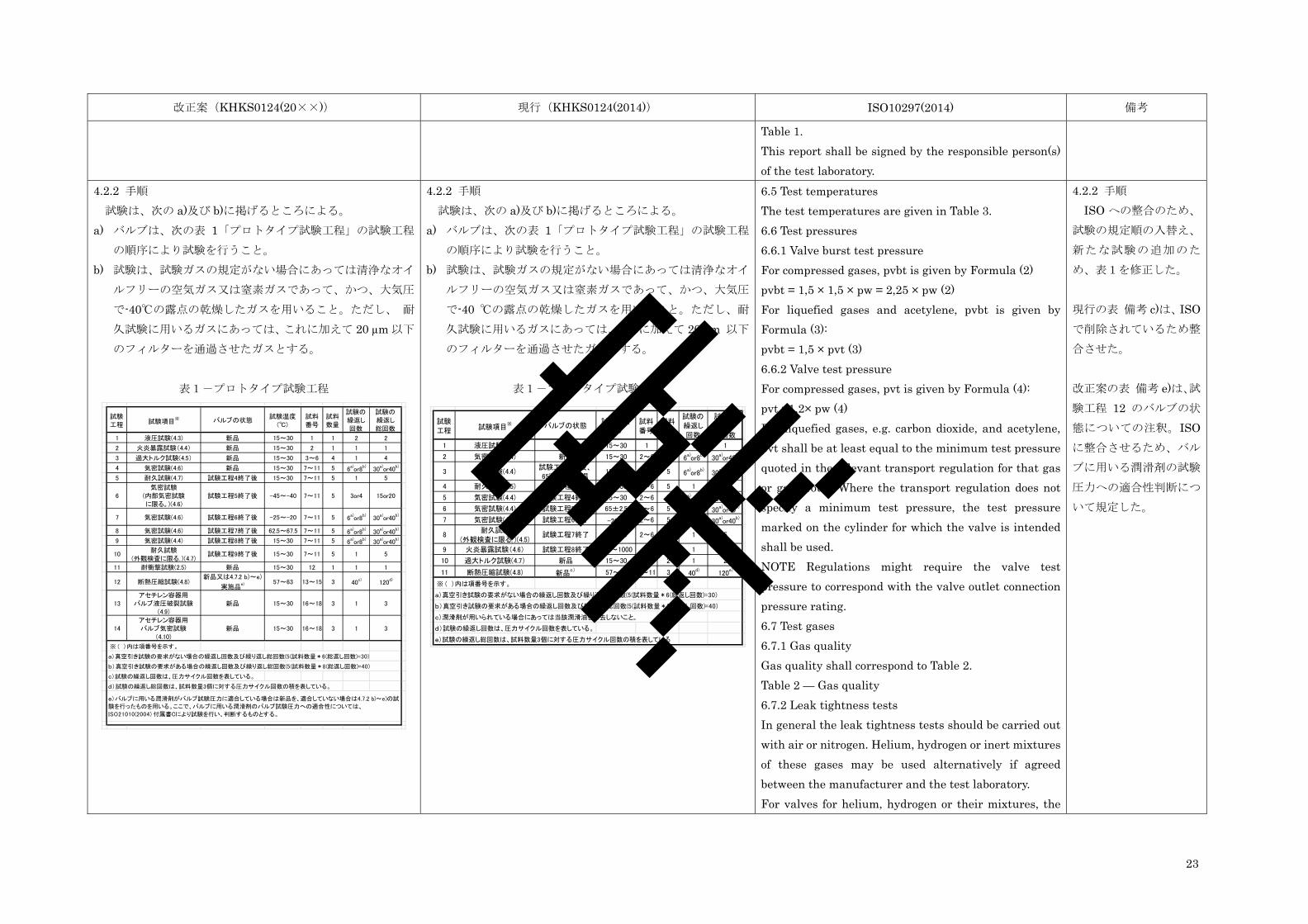
4.2.2 手順 試験は、次の a)及び b)に掲げるところによる。 a) バルブは、次の表 1「プロトタイプ試験工程」の試験工程
の順序により試験を行うこと。 b) 試験は、試験ガスの規定がない場合にあっては清浄なオイ
ルフリーの空気ガス又は窒素ガスであって、かつ、大気圧
で-40℃の露点の乾燥したガスを用いること。ただし、 耐久試験に用いるガスにあっては、これに加えて 20 µm 以下
のフィルターを通過させたガスとする。
表1-プロトタイプ試験工程
4.2.2 手順 試験は、次の a)及び b)に掲げるところによる。
a) バルブは、次の表 1「プロトタイプ試験工程」の試験工程
の順序により試験を行うこと。 b) 試験は、試験ガスの規定がない場合にあっては清浄なオイ
ルフリーの空気ガス又は窒素ガスであって、かつ、大気圧
で-40 ℃の露点の乾燥したガスを用いること。ただし、耐
久試験に用いるガスにあっては、これに加えて 20 µm 以下
のフィルターを通過させたガスとする。
表1-プロトタイプ試験工程
6.5 Test temperatures The test temperatures are given in Table 3. 6.6 Test pressures 6.6.1 Valve burst test pressure For compressed gases, pvbt is given by Formula (2) pvbt = 1,5 × 1,5 × pw = 2,25 × pw (2) For liquefied gases and acetylene, pvbt is given by Formula (3): pvbt = 1,5 × pvt (3) 6.6.2 Valve test pressure For compressed gases, pvt is given by Formula (4): pvt =1,2× pw (4) For liquefied gases, e.g. carbon dioxide, and acetylene, pvt shall be at least equal to the minimum test pressure quoted in the relevant transport regulation for that gas or gas group. Where the transport regulation does not specify a minimum test pressure, the test pressure marked on the cylinder for which the valve is intended shall be used. NOTE Regulations might require the valve test pressure to correspond with the valve outlet connection pressure rating. 6.7 Test gases 6.7.1 Gas quality Gas quality shall correspond to Table 2. Table 2 — Gas quality 6.7.2 Leak tightness tests In general the leak tightness tests should be carried out with air or nitrogen. Helium, hydrogen or inert mixtures of these gases may be used alternatively if agreed between the manufacturer and the test laboratory. For valves for helium, hydrogen or their mixtures, the
4.2.2 手順 ISO への整合のため、
試験の規定順の入替え、
新たな試験の追加のた
め、表1を修正した。 現行の表 備考 c)は、ISOで削除されているため整
合させた。 改正案の表 備考 e)は、試
験工程 12 のバルブの状
態についての注釈。ISOに整合させるため、バル
ブに用いる潤滑剤の試験
圧力への適合性判断につ
いて規定した。
試験
工程 試験項目※ バルブの状態
試験温度
(℃)
試料
番号
試料
数量
試験の
繰返し
回数
試験の
繰返し
総回数
1 液圧試験(4.3) 新品 15~30 1 1 2 2
2 火炎暴露試験(4.4) 新品 15~30 2 1 1 1
3 過大トルク試験(4.5) 新品 15~30 3~6 4 1 4
4 気密試験(4.6) 新品 15~30 7~11 5 6a)or8
b)30
a)or40
b)
5 耐久試験(4.7) 試験工程4終了後 15~30 7~11 5 1 5
6
気密試験
(内部気密試験
に限る。)(4.6)
試験工程5終了後 -45~-40 7~11 5 3or4 15or20
7 気密試験(4.6) 試験工程6終了後 -25~-20 7~11 5 6a)or8
b)30
a)or40
b)
8 気密試験(4.6) 試験工程7終了後 62.5~67.5 7~11 5 6a)or8
b)30
a)or40
b)
9 気密試験(4.4) 試験工程8終了後 15~30 7~11 5 6a)or8
b)30
a)or40
b)
10耐久試験
(外観検査に限る。)(4.7)試験工程9終了後 15~30 7~11 5 1 5
11 耐衝撃試験(2.5) 新品 15~30 12 1 1 1
12 断熱圧縮試験(4.8)新品又は4.7.2 b)~e)
実施品e) 57~63 13~15 3 40
c)120
d)
13
アセチレン容器用
バルブ液圧破裂試験
(4.9)
新品 15~30 16~18 3 1 3
14
アセチレン容器用
バルブ気密試験
(4.10)
新品 15~30 16~18 3 1 3
※ ( )内は項番号を示す。
a)真空引き試験の要求がない場合の繰返し回数及び繰り返し総回数(5(試料数量*6(総返し回数)=30)
b)真空引き試験の要求がある場合の繰返し回数及び繰り返し総回数(5(試料数量*8(総返し回数)=40)
c)試験の繰返し回数は、圧力サイクル回数を表している。
d)試験の繰返し総回数は、試料数量3個に対する圧力サイクル回数の積を表している。
e)バルブに用いる潤滑剤がバルブ試験圧力に適合している場合は新品を、適合していない場合は4.7.2 b)~e)の試
験を行ったものを用いる。ここで、バルブに用いる潤滑剤のバルブ試験圧力への適合性については、
ISO21010(2004) 付属書Cにより試験を行い、判断するものとする。
試験
工程 試験項目※ バルブの状態
試験温度
(℃)
試料
番号
試料
数量
試験の
繰返し
回数
試験の
繰返し
総回数
1 液圧試験(4.3) 新品 15~30 1 1 1 1
2 気密試験(4.4) 新品 15~30 2~6 5 6a)or8
b)30
a)or40
b)
3 気密試験(4.4)試験工程2の後、
65℃5日間加温15~30 2~6 5 6
a)or8
b)30
a)or40
b)
4 耐久試験(4.5) 試験工程3終了 15~30 2~6 5 1 5
5 気密試験(4.4) 試験工程4終了 15~30 2~6 5 6a)or8
b)30
a)or40
b)
6 気密試験(4.4) 試験工程5終了 65±2.5 2~6 5 6a)or8
b)30
a)or40
b)
7 気密試験(4.4) 試験工程6終了 -200-5 2~6 5 6
a)or8
b)30
a)or40
b)
8耐久試験
(外観検査に限る。)(4.5)試験工程7終了 15~30 2~6 5 1 5
9 火炎暴露試験(4.6) 試験工程8終了 800~1000 2 1 1 1
10 過大トルク試験(4.7) 新品 15~30 7,8 2 1 2
11 断熱圧縮試験(4.8) 新品c) 57~63 9~11 3 40
d)120
e)
※ ( )内は項番号を示す。
a)真空引き試験の要求がない場合の繰返し回数及び繰り返し総回数(5(試料数量*6(総返し回数)=30)
b)真空引き試験の要求がある場合の繰返し回数及び繰り返し総回数(5(試料数量*8(総返し回数)=40)
c)潤滑剤が用いられている場合にあっては当該潤滑油を除去しないこと。
d)試験の繰返し回数は、圧力サイクル回数を表している。
e)試験の繰返し総回数は、試料数量3個に対する圧力サイクル回数の積を表している案
24
改正案(KHKS0124(20××)) 現行(KHKS0124(2014)) ISO10297(2014) 備考
test gas shall be helium, hydrogen or an inert mixture of these gases. WARNING — Caution should be taken during handling and testing with hydrogen due to flammability risks. Proper training, procedures and precautions shall be in place prior to testing. 6.7.3 Endurance test In general the endurance test should be carried out with air or nitrogen. Other gases may be used alternatively if agreed between the manufacturer and the test laboratory. 6.7.4 Oxygen pressure surge test The oxygen pressure surge test shall be carried out with oxygen.
規定なし 規定なし 6.8 Test schedule The tests shall be carried out in accordance with the schedule given in Table 3. NOTE See Annex D for an example test schedule for a valve design with material variants.
Table3 を KHKS 表 1 と
整合させた。
4.3 液圧試験 4.3.1 一般 バルブ(アセチレン用バルブを除く。)は、4.3.2 に定める方
法に従って、液圧試験を行い、4.3.3 の基準に合格すること。 4.3.2 試験の方法 試験は、次の a)から d)までに定めるところによること。 a) 試験は、4.2.2 表 1「プロトタイプ試験工程」の試験工程1
に定めるバルブの状態、試験温度、試料番号、試料数量、
試験の繰返し回数及び試験の繰返し総回数に従って行う。 b) 試験は、安全弁を除去した開口部を密閉し、バルブを閉じ
た状態において容器接続口から加圧し、次に、ガス充塡口
を密閉し、バルブを開いた状態において容器接続口から加
圧して行う。 c) 試験媒体には水又はその他適当な液体を使用し、弁箱内に
水等を満たして空気が残らないようにした後、当該バルブ
が装着される容器に充塡すべきガスが圧縮ガスにあっては
4.3 液圧試験 4.3.1 一般 バルブは、4.3.2 に定める方法に従って、液圧試験を行い、
4.3.3 の基準に合格すること。 4.3.2 試験の方法 試験は、次の a)から d)までに定めるところによること。
a) 試験は、4.2.2 表 1「プロトタイプ試験工程」の試験工程1
に定めるバルブの状態、試験温度、試料番号、試料数量、
試験の繰返し回数及び試験の繰返し総回数に従って行う。 b) 試験は、ガス充てん口、安全弁を除去した開口部を密閉し、
バルブを開いた状態において容器接続口から加圧して行
う。 c) 試験媒体には水又はその他適当な液体を使用し、弁箱内に
水等を満たして空気が残らないようにした後、当該バルブ
が装着される容器に充てんすべきガスが圧縮ガスにあって
6.9 Hydraulic burst pressure test For VIPR this test does not cover the low pressure chamber. NOTE 1 The pressure test for the low pressure chamber of VIPR is given in ISO 22435 or ISO 10524-3, respectively. The burst pressure test shall be carried out consecutively on the same test sample in the following order: a) the valve seat in closed position (valve outlet connection(s) opened); and NOTE 2 This requirement is to meet transport regulation. b) the valve seat in open position (valve outlet connection(s) closed and for VIPR the pressure regulator valve closed or held in the closed position), except for
ISO への整合のため、ア
セチレン用バルブは、4.9に規定した。 b)ISO 整合のため、バル
ブが閉の状態での試験を
追加した。 c) ISO 整合のため、圧縮
ガスの試験圧力を 1.8 倍
→2.25 倍とした。
案
25
改正案(KHKS0124(20××)) 現行(KHKS0124(2014)) ISO10297(2014) 備考
高充塡圧力の 2.25 倍以上の圧力を、液化ガスにあって
はバルブ試験圧力の 1.5 倍以上の圧力をそれぞれ除々に加
えること。 d) 試験は、試験圧力に達した後その圧力を 2 分間以上保持し、
目視により行う。 4.3.3 合格基準 変形又は破裂のないこと。
は 高充てん圧力の 1.8 倍以上の圧力を、液化ガスにあっ
てはバルブ試験圧力の 1.5 倍以上の圧力を、圧縮アセチレ
ンガスにあっては 45 MPa 以上の圧力をそれぞれ徐々に加
えること。 d) 試験は、試験圧力に達した後その圧力を 2 分間以上保持し、
目視により行う。 4.3.3 合格基準 変形又は破裂のないこと。
valves for acetylene, see Annex B. Valves equipped with actuators shall be opened according to the manufacturer’s specification. Water or another suitable liquid shall be used as test medium. The hydraulic pressure shall be applied via the valve inlet connection and be raised continuously and gradually until at least pvbt is reached. The pressure shall be maintained for at least 2 min with the hydraulic pump turned off. For the test in the closed position it is permissible for the valve to leak through the seat at a pressure above pvt but below pvbt provided no parts are ejected.
4.4 火炎暴露試験 4.4.1 一般 バルブは、次の 4.4.2 に定める方法に従って火炎暴露試験を
行い、4.4.3 に定める基準に合格すること。 4.4.2 試験の方法 試験は、次の a)から c)までに掲げるところによる。 a) 試験は、4.2.2 表 1「プロトタイプ試験工程」の試験工程 2
に定めるバルブの状態、試験温度、試料番号、試料数量、
試験の繰返し回数及び試験の繰返し総回数に従って行う。 b) バルブを全開にした状態において、温度 800 ℃以上
1 000 ℃以下及び長さ約 150 mm の LP ガスの火炎にバ
ルブ開閉操作部を 1 分間以上晒す。 c) 火炎は、弁開閉操作部を完全に包むようにする。 4.4.3 合格基準 冷却後のバルブ開閉操作部は、手動によりバルブの閉止がで
きるものであること。
4.6 火炎暴露試験 4.6.1 一般 バルブは、次の 4.6.2 に定める方法に従って火炎暴露試験を
行い、4.6.3 に定める基準に合格すること。 4.6.2 試験の方法 試験は、次の a)から c)までに掲げるところによる。
a) 試験は、4.2.2 表 1「プロトタイプ試験工程」 の試験工程 9 に定めるバルブの状態、試験温度、試料番号、試料数量、
試験の繰返し回数及び試験の繰返し総回数に従って行う。 b) バルブを全開にした状態において、温度 800 ℃以上
1 000 ℃以下及び長さ約 150 mm の LP ガスの火炎にバ
ルブ開閉操作部を 1 分間以上晒す。 c) 火炎は、弁開閉操作部を完全に包むようにする。 4.6.3 合格基準 冷却後のバルブ開閉操作部は、手動によりバルブの閉止ができ
るものであること。
6.10 Flame impingement test The valve operating device of the test sample in the open position shall be exposed for 1 min s 0 +5 to a LPG blowpipe flame of approximately 150 mm length, such that the flame reaches a typical temperature of between 800 °C and 1 000 °C. The valve operating device shall be completely enveloped by the flam
ISO 整合のため、試験の
規定順序を変更。
4.5 過大トルク試験 4.5.1 一般 バルブは、次の 4.5.2 に定める方法に従って、バルブ閉止時
過大トルク試験及びバルブ開放時過大トルク試験(以下「過大
トルク試験」と総称する。)を行い、4.5.3 の基準に合格するこ
と。
4.7 過大トルク試験 4.7.1 一般 バルブは、次の 4.7.2 に定める方法に従って、バルブ閉止時過
大トルク試験及びバルブ開放時過大トルク試験 (以下「過大
トルク試験」と総称する。)を行い、4.7.3 の基準に合格するこ
と。
6.11 Excessive torque tests 6.11.1 General If the valve is designed for an intentional failure mode at Tf, e.g. handwheel or spindle failure to occur at a value less than the valve given in Table 1, the manufacturer shall specify the intentional failure
ISO 整合のため、試験の
規定順序を変更。
案
26
改正案(KHKS0124(20××)) 現行(KHKS0124(2014)) ISO10297(2014) 備考
4.5.2 試験の方法 試験は、次の a)から d)までに定めるところによる。 a) 試験は、4.2.2 表 1「プロトタイプ試験工程」の試験工程 3
に定めるバルブの状態、試験温度、試料番号、試料数量、
試験の繰返し回数及び試験の繰返し総回数に従って大気
圧により行う。 b) 過大トルク試験においてバルブを閉止又は開放するトル
クは、1 個のバルブについて、ハンドルの直径(単位 mm(以下同じ。))を 65 mm で除した値に 20 N・m を乗じた
値以上の値とする。ただし、キー溝式(レンチ式)の構造
を有するバルブのトルクにあっては、故障トルクを 1.25で除した値以上の値とする。
c) バルブ閉止時過大トルク試験は、b)に規定するトルクまで
徐々に増加させて閉止させた後、破壊が起こるまでトルク
を負荷する。 d) バルブ開放時過大トルク試験のトルクは、他の 1 個のバル
ブについて、b)に規定する値まで除々に増加させて開放さ
せた後、破壊が起こるまでトルクを負荷する。 4.5.3 合格基準 次の a)から c)までに定めるところによる。 a) バルブ閉止時過大トルク試験にあっては、4.5.2 b)に規定さ
れたトルクまでバルブに変形がなく、かつ、当該トルクに
1.25 を乗じた値で破壊しないこと。ここで、破壊とは、圧
力の保持ができない状態をいう(以下 4.5.3 b)において同
じ)。 b) バルブ開放時過大トルク試験にあっては、4.5.2 b)に規定さ
れたトルクまでバルブに変形がなく、かつ、当該トルクに
1.25 を乗じた値で破壊しないこと。 c) バルブ開閉機構は、弁箱からグランドナットが外れるトル
クまで耐えられないものであること。ただし、圧縮アセチ
レンガスを充塡すべき容器に装着されるバルブにあって
はこの限りでない。
4.7.2 試験の方法 試験は、次の a)から d)までに定めるところによる。 a) 試験は、4.2.2 表 1「プロトタイプ試験工程」の試験工程
10 に定めるバルブの状態、試験温度、試料番号、試料数量、
試験の繰返し回数及び試験の繰返し総回数に従って大気圧
により行う。 b) 過大トルク試験においてバルブを閉止又は開放するトルク
は、1 個のバルブについて、 ハンドルの直径(単位 mm(以下同じ。))を 65 mm で除した値に 20 N・m を乗じた
値以上の値とする。ただし、ハンドルの有無にかかわらず
キー溝式又はダイヤフラム式の構造を有するバルブのトル
クにあっては、20 N・m を超える値以上の値とする。 c) バルブ閉止時過大トルク試験は、b)に規定するトルクまで
徐々に増加させて閉止させた後、破壊が起こるまでトルク
を負荷する。 d) バルブ開放時過大トルク試験のトルクは、他の 1 個のバル
ブについて、b)に規定する値まで徐々に増加させて開放さ
せた後、破壊が起こるまでトルクを負荷する。 4.7.3 合格基準 次の a)から c)までに定めるところによる。
a) バルブ閉止時過大トルク試験にあっては、4.7.2 b)に規定さ
れたトルクまでバルブに変形がなく、かつ、当該トルクに
1.25 を乗じた値で破壊しないこと。ここで、破壊とは、圧
力の保持ができない状態をいう(以下 4.7.3 b)において同
じ)。 b) バルブ開放時過大トルク試験にあっては、4.7.2 b)に規定さ
れたトルクまでバルブに変形がなく、かつ、当該トルクに
1.25 を乗じた値で破壊しないこと。 c) バルブ開閉機構は、弁箱からグランドナットが外れるトル
クまで耐えられないものであること。ただし、圧縮アセチ
レンガスを充てんすべき容器に装着されるバルブにあって
はこの限りでない。
torque value and the test samples shall be tested at this stated value. 6.11.2 Handwheel operated valves For handwheel operated valves a closing torque on one test sample shall gradually be increased to To according to Table 1. At To the valve shall be able to work without noticeable difficulties. To determine Tf, a closing torque on a different test sample than used for the determination of To shall gradually be increased slowly until failure of any part of the valve operating mechanism or valve operating device occurs. This test shall then be repeated on two other test samples under the same conditions, but applying an opening torque instead of a closing torque. The value of Tf determined from applying a closing and an opening torque shall be not less than the value given in Table 1 or in case of an intentional failure mode, the value specified by the manufacturer. 6.11.3 Key/toggle operated valves For key/toggle operated valves Tf first shall be determined using two test samples. To determine Tf a closing torque on one test sample and an opening torque on a second test sample shall gradually be increased slowly until failure of any part of the valve operating mechanism or operating device occurs. Then To shall be calculated on the basis of the lowest of these two failure torque values using the formula given in Table 1. This value of To shall be applied on two other test samples then used for the determination of Tf.
4.6 気密試験 4.6.1 一般 バルブは、次の 4.6.2 に定めるところに従って内部気密試験
4.4 気密試験 4.4.1 一般 バルブは、次の 4.4.2 に定めるところに従って内部気密試験
6.12 Leak tightness tests 6.12.1 General Each internal and external leak tightness test
案
27
改正案(KHKS0124(20××)) 現行(KHKS0124(2014)) ISO10297(2014) 備考
及び外部気密試験(以下総称して「気密試験」という。)を行
い、4.6.3 の基準に合格すること。 4.6.2 試験の方法 試験は、4.2.2 表 1 「プロトタイプ試験工程」の試験工程 4、6、7、8 及び 9 に定めるバルブの状態、試験温度、試料番号、
試料数量、試験の繰返し回数及び試験の繰返し総回数に従い、
a)から c)までに定めるところによる。 a) 内部気密試験にあっては次の 1)から 5)までに定めるところ
による。 1) 0.05 MPa、1 MPa 及びバルブ試験圧力(-45 ℃~-40 ℃で
行う試験にあってはバルブ試験圧力に限る。)以上の圧力を加
える。 2) 真空引き試験が必要なバルブの試験にあっては、1)に加え、
0.5×10⁻³ MPa(絶対圧)以下の圧力に減圧させる。 3) ガス充塡口、安全弁を除去した開口部を密閉し、バルブを
開いた状態において容器接続口から加圧して行う。 4) 小閉止トルクでバルブを閉止し、ガス充塡口を開放して
から1分間以上その状態を保持した後、内部気密について漏れ
量の測定を行うこと。 5) 4)の試験において、温度 20 ℃及び大気圧 101.3 kPa の状態
で 6 cm3/h を超える漏れが確認された場合にあっては、4)にお
いて規定されている 小閉止トルク以上のトルクを負荷して
バルブを閉止した後、再度 1)から 4)までの試験を行うことがで
きる。 b) 外部気密試験にあっては次の 1)から 5)までに定めるところ
による。 1) 0.05 MPa、1 MPa 及びバルブ試験圧力以上の圧力を加える。
2) 真空引き試験が必要なバルブの試験にあっては、1)に加え、
0.5×10⁻³ MPa(絶対圧)以下の圧力に減圧させる。
及び外部気密試験(以下総称して「気密試験」という。)を行
い、4.4.3 の基準に合格すること。 4.4.2 試験の方法 試験は、4.2.2 表 1「プロトタイプ試験工程」の試験工程 2、
3、5、6 及び 7 に定めるバルブの状態、試験温度、試料番号、
試料数量、試験の繰返し回数及び試験の繰返し総回数に従い、
a)から c)までに定めるところによる。 a) 内部気密試験にあっては次の 1)から 4)までに定めるところ
による。 1) 次の表 2「充てんすべきガスの種類と気密試験圧力」の左欄
に掲げる当該バルブに装着される容器に充てんすべきガスの
種類に応じ、同表右欄に掲げる気密試験圧力(0.5×10⁻³ MPa(絶対圧)を除くもの)以上の圧力を加える。この場合におい
て、真空引き試験が必要なバルブの試験にあってはこれらに加
えて、0.5×10⁻³ MPa(絶対圧)以下の圧力に減圧させる。 表 2 -充てんすべきガスの種類と気密試験圧力 2) ガス充てん口、安全弁を除去した開口部を密閉し、バルブを
開いた状態において容器接続口から加圧して行う。 3) 小閉止トルクでバルブを閉止し、ガス充てん口を開放して
から1分間以上その状態を保持した後、内部気密について漏れ
量の測定を行うこと。 4) 3)の試験において、温度 20 ℃及び大気圧 101.3 kPa の状態
で 6 cm3/h を超える漏れが確認された場合にあっては、3)にお
いて規定されている 小閉止トルク以上のトルクを負荷して
バルブを閉止した後、再度 1)から 3)までの試験を行うことがで
きる。 b) 外部気密試験にあっては次の 1)から 4)までに定めるところ
による。 1) 次の表 3「充てんすべきガスの種類と気密試験圧力」の左欄
に掲げる当該バルブに装着される容器に充てんすべきガスの
種類に応じ、同表右欄に掲げる気密試験圧力(0.5×10⁻³ MPa(絶対圧)を除くもの)以上の圧力を加える。 この場合において、真空引き試験が必要なバルブの試験にあっ
temperature sequence (see Table 3) shall comprise the test pressures as given in Table 4 in increasing order for room and high temperature tests and decreasing order for −20 °C test. NOTE This order was chosen to reflect normal cylinder operations. Table 4 — Test pressures for leak tightness tests
Vacuumifrequired(e.g.bythemanufacturer).An
exampleofavacuumtestisgiveninAnnexE.
0,5bar
10bar
pvt(see6.6.2)
Prior to the test the valves shall achieve the relevant test temperature as given in Table 3 and shall be maintained at that temperature throughout the complete test procedure. After the valves are tested at low temperatures allow the test samples to naturally come to room temperature before applying high temperature to avoid temperature shocks between tests. 6.12.2 Internal leak tightness test 6.12.2.1 General Tc shall be specified by the manufacturer and shall be verified by the test laboratory during the first leak tightness test (Test 4 according to Table 3). The internal leak tightness shall be determined for each of the submitted test samples in accordance with 6.12.2.2 and 6.12.2.3. 6.12.2.2 Test at room and high temperature The test shall be carried out in the following order: a) Seal valve outlet connection(s). b) Open the valve. c) The pressure shall be applied to the valve inlet and be raised until the test pressure is reached.
1) ISO ではガスの種類
によらず気密試験圧力が
設定されたため、整合さ
せた。
案
28
改正案(KHKS0124(20××)) 現行(KHKS0124(2014)) ISO10297(2014) 備考
3) 試験は、容器接続口又はガス充塡口及び安全弁を除去した
開口部を密閉し、バルブを全開にした状態において開放してい
るガス充塡口又は容器接続口から加え、外部気密について行
う。 4) 3)の試験の後、バルブを半開にした状態において気密試験圧
力以上の圧力を開放しているガス充塡口又は容器接続口から
加え、外部気密について漏れ量の測定を行う。 5) 4)の試験において、温度 20 ℃及び大気圧 101.3 kPa の状態
で 6 cm3/h を超える漏れが確認された場合にあっては、4)にお
けるバルブの半開の状態とは異なる半開の状態にした後、再度
1)から 4)までの試験を行うことができる。 c) 表 1「プロトタイプ試験工程」の試験工程 7 の試験温度
-20 ℃+0-5は、ハンドルを回転している間に測定し、当該温
度であることを確認する。 4.6.3 合格基準 温度 20 ℃及び大気圧 101.3 kPa の状態において 6 cm3/h を
超える漏れがないこと。
てはこれらに加えて、0.5×10⁻³ MPa(絶対圧)以下の圧力に
減圧させる。 表 3 -充てんすべきガスの種類と気密試験圧力 2) 試験は、容器接続口又はガス充てん口及び安全弁を除去した
開口部を密閉し、バルブを全開にした状態において開放してい
るガス充てん口又は容器接続口から加え、外部気密について行
う。 3) 2)の試験の後、バルブを半開にした状態において気密試験圧
力以上の圧力を開放しているガス充てん口又は容器接続口か
ら加え、外部気密について漏れ量の測定を行う。 4) 3)の試験において、温度 20 ℃及び大気圧 101.3 kPa の状態
で 6 cm3/h を超える漏れが確認された場合にあっては、3)にお
けるバルブの半開の状態とは異なる半開の状態にした後、再度
1)から 3)までの試験を行うことができる。 c) 表 1「プロトタイプ試験工程」の試験工程 7 の試験温度
-20 ℃+0-5は、ハンドルを回転している間に測定し、当該温
度であることを確認する。 4.4.3 合格基準 温度 20 ℃及び大気圧 101.3 kPa の状態において 6 cm3/h を
超える漏れがないこと。
d) Close the valve to the closing torque. For the leak tightness test carried out before the endurance test the closing torque is Tc. For the leak tightness test carried out after the endurance test the closing torque required to achieve tightness shall not be greater than Te,end. e) Open the valve outlet connection. f) Wait at least 1 min before measuring the seat leakage rate. NOTE Some valve designs require extended time before measuring the leak due to trapped air in the non-gas wetted area. This test sequence shall be repeated for each test pressure given in Table 4. Before applying the next test pressure it is allowed to vent the valve. 6.12.2.3 Test at low temperatures The test shall be carried out in the following order: a) Seal valve outlet connection(s). b) Open the valve. c) The pressure shall be applied to the valve inlet and be raised until the test pressure is reached. d) Close the valve to the closing torque. The closing torque required to achieve tightness shall not be greater than Te,end. For the leak tightness test at −40 °C the valve shall be closed at room temperature before being cooled down [see f)]. e) Open the valve outlet connection. f) For the leak tightness test at −40 °C the valve then shall be cooled down avoiding temperature shocks. It shall be ensured that after cooling the valve down it is at test pressure before measuring the leakage rate. g) Wait at least 1 min before measuring the seat leakage rate. NOTE Some valve designs require extended time before measuring the leak due to trapped air in the non-gas wetted area.
案
29
改正案(KHKS0124(20××)) 現行(KHKS0124(2014)) ISO10297(2014) 備考
This test sequence shall be repeated for each test pressure given in Table 4 except for the test at −40 °C where only pvt is required. Before applying the next test pressure it is allowed to vent the valve. To carry out the tests at −20 °C it is only necessary to raise the temperature without passing through room temperature. 6.12.3 External leak tightness test The external leak tightness shall be determined for each of the submitted test samples in the following order: a) Blank all existing openings of the valve except theone used to apply the test pressure.b) Fully open the valve.c) The pressure shall be applied to the selected openingand be raised until the test pressure is reached.Measure the total leakage rate. In addition, except fordiaphragm valve, the leakage rate shall be determinedwith the valve operating mechanism in twointermediate positions (e.g. approximately 2/3 and 1/3 ofthe ‘fully open’ position).Wait at least 1 min before measuring the seat leakagerate.This test sequence shall be repeated for each testpressure given in Table 4. Before applying the next testpressure it is allowed to vent the valve.NOTE Some valve designs require extended time beforemeasuring the leak due to trapped air in the non-gaswetted area.
4.7 耐久試験 4.7.1 一般 バルブは、次の 4.7.2 に定める方法に従って耐久試験を行い、
4.7.3 の基準に合格すること。 4.7.2 試験の方法 試験は、次の a)から g)までに定めるところによる。
a) 試験は、表 1「プロトタイプ試験工程」の試験工程 5 に定
4.5 耐久試験 4.5.1 一般 バルブは、次の 4.5.2 に定める方法に従って耐久試験を行い、
4.5.3 の基準に合格すること。 4.5.2 試験の方法 試験は、次の a)から g)までに定めるところによる。
a) 試験は、表 1「プロトタイプ試験工程」の試験工程 4 に定
6.13 Endurance test An endurance test of 2 000 cycles (opening and closing) shall be carried out using Te as given in Table 1 at pvt. The valve inlet shall remain pressurized to pvt throughout the entire test. The valve outlet shall be connected to a venting device that remains closed during the closing and opening portions of the cycle.
案
30
改正案(KHKS0124(20××)) 現行(KHKS0124(2014)) ISO10297(2014) 備考
めるバルブの状態、試験温度、試料番号、試料数量、試験
の繰返し回数及び試験の繰返し総回数に従って行う。 b) 試験は、次の 1)から 3)までに掲げるところによる。 1) ガス充塡口を密閉した状態においてバルブ試験圧力以上の
圧力を容器取付部から加えた後、バルブを閉止し、その状態を
6 秒間以上保持する。 2) 密閉していたガス充塡口を 3 秒間以上開放して大気圧にし
た後、再びガス充塡口を密閉し、その状態を 6 秒間以上保持す
る。 3) ハンドル等のバルブ開閉操作部を全開にしてその位置から
閉止方向に 45°戻した状態の位置においてバルブ試験圧力以上
の圧力を容器取付部から加えた後、その状態を 6 秒間以上保持
する。 c) b)の試験は、3 分毎 1 回以上 1 分毎 3 回以下の割合で 2 000
回以上繰り返す。 d) b)の試験において、バルブを閉止する時のトルクは、ハン
ドルの直径を 65 mm で除した値に 7 N・m を乗じた値とす
る。キー溝式(レンチ式)の構造を有するバルブを閉止す
る時のトルクにあっては、故障トルクを 3.75 で除した値
(金属接触によりシールするものにあっては、バルブ製造
者が指定する任意の値)とする。 e) b)の試験において、バルブ試験圧力以上の圧力に昇圧する
ことができなくなった場合、バルブを閉止するトルクは、
以下の 1)及び 2)とすることができる。 1) ダイヤフラム式の構造を有するバルブは、d)で規定されて
いるトルクの値に 1.5 を乗じた値であって、16 N・m 以下
の値(キー溝式以外のものに限る。)とする。 2) 金属接触によりシールするバルブであってキー溝式でない
ものにあっては、バルブ製造者が指定する任意の値に 1.5を乗じた値(16 N・m 以下の値)と、キー溝式のものにあ
っては、故障トルクに 1.25 を乗じた値とする。 f) d)の試験を行う場合の許容誤差は、それぞれのトルク値の
±5%以下とする。
めるバルブの状態、試験温度、試料番号、試料数量、試験
の繰返し回数及び試験の繰返し総回数に従って行う。 b) 試験は、次の 1)から 3)までに掲げるところによる。 1) ガス充てん口を密閉した状態においてバルブ試験圧力以上
の圧力を容器取付部から加えた後、バルブを閉止し、その状態
を 6 秒間以上保持する。 2) 密閉していたガス充てん口を 3 秒間以上開放して大気圧に
した後、再びガス充てん口を密閉し、その状態を 6 秒間以上保
持する。 3) ハンドル等のバルブ開閉操作部を全開にしてその位置から
閉止方向に 45°戻した状態の位置においてバルブ試験圧力以上
の圧力を容器取付部から加えた後、その状態を 6 秒間以上保持
する。 c) b)の試験は、毎分 1 回以上 3 回以下の割合で 2 000 回以上
繰り返す。 d) b)の試験において、バルブを閉止する時のトルクは、ハン
ドルの直径が32.5 mm未満のものにあっては当該ハンドル
の直径を 65 mm で除した値に 7 N・m を乗じた値の 2 倍の値と、ハンドルの直径が 32.5 mm 以上のもの又はハンド
ルのないものにあっては 7 N・m とする。ただし、ハンド
ルの有無にかかわらずキー溝式又はダイヤフラム式の構造
を有するバルブを閉止する時のトルクにあっては、 小閉
止トルクに 1.5 を乗じた値とする。 e) d)の試験を行う場合の許容誤差は、それぞれのトルク値の
±5 %以下とする。
After each closure, by opening the venting device, the pressure downstream of the valve seat shall be released to atmosphere to reach atmospheric pressure. For VIPR the pressure regulator shall be in the setting which allows maximum gas flow through the regulator seat when the VIPR will be vented. For handwheel operated valves the valve shall be operated by the handwheel. Some valve designs require special operation of the handwheel to engage with the valve operating mechanism, e.g. valves with handwheels that incorporate a push to turn locking mechanism. With such valves it is permissible to override this mechanism or to carry out the endurance test manually. For valves equipped with actuators, the test shall be conducted using the manufacturer’s recommended parameters, e.g. actuation pressure, voltage supplies. For valves actuated with a lever the test shall be carried out by operating the lever through its full travel from closed to open. For some VIPR designs test requirement and test procedure have to be decided on a case by case basis and agreed between the manufacturer and the test laboratory. Te and the leakage (by pressure drop) shall be established immediately before commencing every cycle. If the pressure drop due to the valve leaking externally is greater than 10 bar, the valve has failed the test. For some valve designs as given in Table 1 it is permitted to increase Te during the test when the internal tightness is no longer achieved. For those designs, if the pressure measured at the high pressure transducer (key no. 4 of Figure F.1) after having vented the outlet is more than 5 bar, Te shall
c) 試験の繰り返し速度
を ISO に整合させた。 d)、e) トルク値を ISOに整合させた。
案
31
改正案(KHKS0124(20××)) 現行(KHKS0124(2014)) ISO10297(2014) 備考
g) d)の試験後、気密試験を行う。試験は、表 1「プロトタイ
プ試験工程」の試験工程 6 に定めるバルブの状態、試験温
度、試料番号、試料数量、試験の繰返し回数及び試験の繰
返し総回数に従い、次の 1)及び 2)に定めるところによる。 1) 内部気密試験にあっては次の 1.1)から 1.5)までに定めると
ころによる。
1.1) 試験は、0.05 MPa、1 MPa 及びバルブ試験圧力以上の圧
力を加える。
1.2) 真空引き試験が必要なバルブの試験にあっては、1.1)に加
え、0.5×10⁻³ MPa(絶対圧)以下の圧力に減圧させる。
1.3) ガス充塡口及び安全弁を除去した開口部を密閉し、バルブ
を開いた状態において気密試験圧力以上の圧力を容器接続口
から 1 分間以上加圧して行う。 1.4) 小閉止トルクでバルブを閉止してから 1 分間以上その
状態を保持した後、内部気密について漏れ量の測定を行う。
1.5) 1.4)の試験において、 温度 20 ℃及び大気圧 101.3 kPa の
状態で 6 cm3/h を超える漏れが確認された場合にあっては、
1.4)において規定されている 小閉止トルク以上のトルクを負
荷してバルブを閉止した後、再度 1.1)から 1.4)までの試験を行
うことができる。
2) 外部気密試験にあっては次の 2.1)から 2.5)までに定めると
ころによる。
2.1) 試験は、0.05 MPa、1 MPa 及びバルブ試験圧力以上の圧
力を加える。
2.2) 真空引き試験が必要なバルブの試験にあっては、2.1)に加
え、0.5×10⁻³ MPa(絶対圧)以下の圧力に減圧させる。
2.3) 容器接続口又はガス充塡口及び安全弁を除去した開口部
を密閉し、バルブを全開にした状態において開放している容器
接続口又は充塡口から加え、外部気密について行う。
f) d)の試験後、気密試験を行う。 試験は、表 1「プロトタイ
プ試験工程」の試験工程 5 に定めるバルブの状態、試験温
度、試料番号、試料数量、試験の繰返し回数及び試験の繰
返し総回数に従い、次の 1)及び 2)に定めるところによる。
1) 内部気密試験にあっては次の 1.1)から 1.4)までに定めると
ころによる。
1.1) 試験は、表 2「充てんすべきガスの種類と気密試験圧力」
の左欄に掲げる当該バルブに装着される容器に充てんすべき
ガスの種類に応じ、同表右欄に掲げる気密試験圧力(0.5×10⁻³ MPa(絶対圧)を除くもの)以上の圧力を加える。 この場合において、真空引き試験が必要なバルブの試験にあっ
てはこれらに加えて 0.5×10⁻³ MPa(絶対圧)以下の圧力に減
圧させる。
1.2) ガス充てん口及び安全弁を除去した開口部を密閉し、バル
ブを開いた状態において気密試験圧力以上の圧力を容器接続
口から 1 分間以上加圧して行う。 1.3) 小閉止トルクでバルブを閉止してから 1 分間以上その
状態を保持した後、内部気密について漏れ量の測定を行う。
1.4) 1.3)の試験において、温度 20 ℃及び大気圧 101.3 kPa の状態で 6 cm3/h を超える漏れが確認された場合にあっては、
1.3)において規定されている 小閉止トルク以上のトルクを負
荷してバルブを閉止した後、再度 1.1)から 1.3)までの試験を行
うことができる。
2) 外部気密試験にあっては次の 2.1)から 2.4)までに定めると
ころによる。
2.1) 試験は、表 3「充てんすべきガスの種類と気密試験圧力」
の左欄に掲げる当該バルブに装着される容器に充てんすべき
ガスの種類に応じ、同表右欄に掲げる気密試験圧力(0.5×10⁻³ MPa(絶対圧)を除くもの)以上の圧力を加える。 この場合において、真空引き試験が必要なバルブの試験にあっ
てはこれらに加えて 0.5×10⁻³ MPa(絶対圧)以下の減圧さ
せる。
2.2) 容器接続口又はガス充てん口及び安全弁を除去した開口
部を密閉し、バルブを全開にした状態において開放している容
器接続口又は充てん口から加え、外部気密について行う。
be increased by nominal 10 % of the allowed torque range (range between Te and Te,end) or 0,5 Nm (whichever is the higher value) but in any case shall not be higher than Te,end. After each closure, by opening the venting device, the pressure downstream of the valve seat shall be released to atmosphere to reach atmospheric pressure. The test equipment shall meet the requirements given in Annex F except if the test is carried out manually. There shall be a pause of at least 6 s at each open and fully closed position. For all subsequent tests, Te,end shall not be exceeded. The test shall be performed at no more than three cycles per minute and no less than one cycle per 3 minutes. The manufacturer may specify a cycle rate within this allowed range.
案
32
改正案(KHKS0124(20××)) 現行(KHKS0124(2014)) ISO10297(2014) 備考
2.4) 2.3)の試験の後、バルブを半開にした状態において開放し
ている容器接続口又は充塡口から加え、外部気密について漏れ
量の測定を行う。 2.5) 2.4)の試験において、温度 20 ℃及び大気圧 101.3 kPa の
状態で 6 cm3/h を超える漏れが確認された場合にあっては、
2.4)におけるバルブの半開の状態とは異なる半開の状態にした
後、再度 2.1)から 2.4)までの試験を行うことができる。 h) 外観検査は、表 1「プロトタイプ試験工程」の試験工程 10
に定めるバルブの状態、試験温度、試料番号、試料数量、
試験の繰返し回数及び試験の繰返し総回数に従い、ダイヤ
フラム、ベローズ、O リング等のシール部材の摩耗及び損
傷状態を目視により行う。 4.7.3 合格基準 次の a)から c)まで定めるところによる。 a) バルブ開閉機構が確実に作動するものであること。 b) 温度 20 ℃及び大気圧 101.3 kPa の状態において 6 cm3/h
を超える漏れがないこと。 c) 外観検査にあっては、ダイヤフラム、ベローズ、O リング
等のシール部材に使用上支障のある摩耗又は損傷のないも
のであること。
2.3) 2.2)の試験の後、バルブを半開にした状態において開放し
ている容器接続口又は充てん口から加え、外部気密について漏
れ量の測定を行う。 2.4) 2.3)の試験において、温度 20 ℃及び大気圧 101.3 kPa の状態で 6 cm3/h を超える漏れが確認された場合にあっては、
2.3)におけるバルブの半開の状態とは異なる半開の状態にした
後、再度 2.1)から 2.3)までの試験を行うことができる。 g) 外観検査は、表 1「プロトタイプ試験工程」の試験工程 8 に
定めるバルブの状態、試験温度、試料番号、試料数量、試
験の繰返し回数及び試験の繰返し総回数に従い、ダイヤフ
ラム、ベローズ、O リング等のシール部材の摩耗及び損傷
状態を目視により行う。 4.5.3 合格基準 次の a)から c)まで定めるところによる。
a) バルブ開閉機構が確実に作動するものであること。 b) 温度 20 ℃及び大気圧 101.3 kPa の状態において 6 cm3/h
を超える漏れがないこと。 c) 外観検査にあっては、ダイヤフラム、ベローズ、O リング
等のシール部材に使用上支障のある摩耗又は損傷のないも
のであること。 4.8 断熱圧縮試験 4.8.1 一般 バルブ(ISO 10156 に規定された酸化力の強いガス又は混合
ガスを充塡する容器に装着されるものに限る。)は、 次の 4.8.2に定める方法に従って断熱圧縮試験を行い、4.8.3 に定める基
準に合格すること。 4.8.2 試験の方法 試験は、次の a)から g)までに定めるところによる。 a) 試験は、表 1「プロトタイプ試験工程」の試験工程 12 に
定めるバルブの状態、試験温度、試料番号、試料数量、試
験の繰返し回数及び試験の繰返し総回数に従って行う。 b) 試験に用いる酸素ガスの純度は、99.5 %(容量比)以上で
あって、かつ、炭化水素の含有量が 100 ppm(容量比)以
下とする。 c) 試験に用いる酸素ガスの温度は、60±3 ℃とする。
4.8 断熱圧縮試験 4.8.1 一般 バルブ(ISO 10156 に規定された酸化力の強いガス又は混合
ガスを充てんする容器に装着されるものに限る。)は、次の 4.8.2に定める方法に従って断熱圧縮試験を行い、4.8.3 に定める基
準に合格すること。 4.8.2 試験の方法 試験は、次の a)から g)までに定めるところによる。 a) 試験は、表 1「プロトタイプ試験工程」の試験工程 11 に定
めるバルブの状態、試験温度、試料番号、試料数量、試験
の繰返し回数及び試験の繰返し総回数に従って行う。 b) 試験に用いる酸素ガスの純度は、99.5 %(容量比)以上で
あって、かつ、炭化水素の含有量が 100 ppm(容量比)以
下とする。 c) 試験に用いる酸素ガスの温度は、60±3 ℃とする。
Annex C (normative) Oxygen pressure surge test C.1 General All valves shall be tested via the valve filling connection. If a valve is used in an application where it can be subjected to an oxygen pressure surge via additional connections the oxygen pressure surge test shall be carried out via all those connections. All main valves shall be tested via the valve filling connection and valve inlet connection. In case lubricants used are not rated for the valve test pressure; the test samples shall be pre-conditioned via the endurance cycling procedure according to 6.13 (without subsequent leak tightness tests and visual examination) before being oxygen pressure surge tested, see 5.2.
案
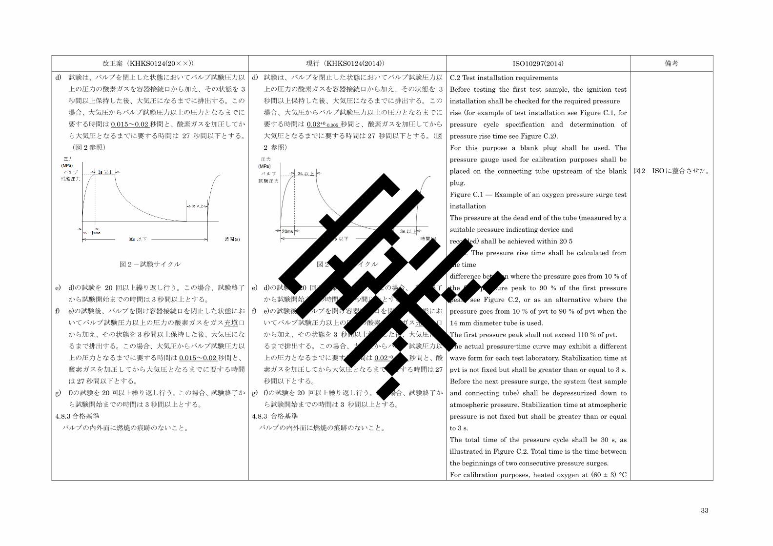
33
改正案(KHKS0124(20××)) 現行(KHKS0124(2014)) ISO10297(2014) 備考
d) 試験は、バルブを閉止した状態においてバルブ試験圧力以
上の圧力の酸素ガスを容器接続口から加え、その状態を 3 秒間以上保持した後、大気圧になるまでに排出する。この
場合、大気圧からバルブ試験圧力以上の圧力となるまでに
要する時間は 0.015~0.02 秒間と、酸素ガスを加圧してか
ら大気圧となるまでに要する時間は 27 秒間以下とする。
(図 2 参照)
図2-試験サイクル
e) d)の試験を 20 回以上繰り返し行う。この場合、試験終了
から試験開始までの時間は 3 秒間以上とする。 f) e)の試験後、バルブを開け容器接続口を閉止した状態にお
いてバルブ試験圧力以上の圧力の酸素ガスをガス充塡口
から加え、その状態を 3 秒間以上保持した後、大気圧にな
るまで排出する。この場合、大気圧からバルブ試験圧力以
上の圧力となるまでに要する時間は 0.015~0.02 秒間と、
酸素ガスを加圧してから大気圧となるまでに要する時間
は 27 秒間以下とする。 g) f)の試験を 20 回以上繰り返し行う。この場合、試験終了か
ら試験開始までの時間は 3 秒間以上とする。 4.8.3 合格基準 バルブの内外面に燃焼の痕跡のないこと。
d) 試験は、バルブを閉止した状態においてバルブ試験圧力以
上の圧力の酸素ガスを容器接続口から加え、その状態を 3 秒間以上保持した後、大気圧になるまでに排出する。この
場合、大気圧からバルブ試験圧力以上の圧力となるまでに
要する時間は 0.02+0-0.005 秒間と、酸素ガスを加圧してから
大気圧となるまでに要する時間は 27 秒間以下とする。(図
2 参照)
図2-試験サイクル
e) d)の試験を 20 回以上繰り返し行う。この場合、 試験終了
から試験開始までの時間は 3 秒間以上とする。 f) e)の試験後、バルブを開け容器接続口を閉止した状態にお
いてバルブ試験圧力以上の圧力の酸素ガスをガス充てん口
から加え、その状態を 3 秒間以上保持した後、大気圧にな
るまで排出する。この場合、大気圧からバルブ試験圧力以
上の圧力となるまでに要する時間は 0.02+0-0.005 秒間と、酸
素ガスを加圧してから大気圧となるまでに要する時間は 27 秒間以下とする。
g) f)の試験を 20 回以上繰り返し行う。この場合、試験終了か
ら試験開始までの時間は 3 秒間以上とする。 4.8.3 合格基準 バルブの内外面に燃焼の痕跡のないこと。
C.2 Test installation requirements Before testing the first test sample, the ignition test installation shall be checked for the required pressure rise (for example of test installation see Figure C.1, for pressure cycle specification and determination of pressure rise time see Figure C.2). For this purpose a blank plug shall be used. The pressure gauge used for calibration purposes shall be placed on the connecting tube upstream of the blank plug. Figure C.1 — Example of an oxygen pressure surge test installation The pressure at the dead end of the tube (measured by a suitable pressure indicating device and recorded) shall be achieved within 20 5 − ms. The pressure rise time shall be calculated from the time difference between where the pressure goes from 10 % of the first pressure peak to 90 % of the first pressure peak, see Figure C.2, or as an alternative where the pressure goes from 10 % of pvt to 90 % of pvt when the 14 mm diameter tube is used. The first pressure peak shall not exceed 110 % of pvt. The actual pressure-time curve may exhibit a different wave form for each test laboratory. Stabilization time at pvt is not fixed but shall be greater than or equal to 3 s. Before the next pressure surge, the system (test sample and connecting tube) shall be depressurized down to atmospheric pressure. Stabilization time at atmospheric pressure is not fixed but shall be greater than or equal to 3 s. The total time of the pressure cycle shall be 30 s, as illustrated in Figure C.2. Total time is the time between the beginnings of two consecutive pressure surges. For calibration purposes, heated oxygen at (60 ± 3) °C
図2 ISOに整合させた。
案
34
改正案(KHKS0124(20××)) 現行(KHKS0124(2014)) ISO10297(2014) 備考
shall be used. Figure C.2 — Determination of pressure rise time and pressure cycle specification C.3 Test procedure Each test shall be carried out as follows: a) Supply oxygen at a temperature of (60 ± 3) °C, directly into the connection of the valve to be tested which shall be mounted in vertical position (if possible), by means of an oxygen compatible metallic tube having an internal diameter of 5 mm (or 14 mm for main valves) and a length of 1 m (or 0,75 m for main valves). The specified dimensions of the tube are essential in order to ensure that a welldefined energy input into the valve to be tested is achieved. b) Perform two test sequences in accordance with Table C.1. The test sample shall be cooled down to at least room temperature at the start of each sequence. Table C.1 — Test sequence for oxygen pressure surge c) The oxygen is heated to (60 ± 3) °C in the oxygen pre-heating device. A quick opening valve (see Figure C.1) controls the admittance of oxygen to the test sample. The test consists in subjecting the test sample to 20 pressure cycles from atmospheric to pvt (see Figure C.2). Before testing the next sample the filling adaptor shall be allowed to cool. It shall be visually examined for damage or worn seal and corrective action taken if necessary.
7 Marking Valves complying with this International Standard shall be durably and legibly marked in service with: a) coded identification of this International Standard: 1) all valves shall be marked with “ISO V” except for the following; 2) valves oxygen pressure surge tested for use as a main
ISO 7 Marking の規定
は、容器則に規定されて
いるため、KHKS には規
定しなかった。
案
35
改正案(KHKS0124(20××)) 現行(KHKS0124(2014)) ISO10297(2014) 備考
valve (see C.1) shall be marked with “ISO VB”; b) manufacturer’s identification; c) year and month (or week) of manufacture, i.e. YY/MM (or YY-WW) or YYYY/MM (or YYYY-WW); d) identification of the valve inlet connection if it is not already required by the relevant inlet connection standard. This identification shall be given by a unique alphanumeric code such as that given in ISO/TR 11364; e) identification of the valve outlet connection if it is not already required by the relevant outlet connection standard. This identification shall be given by a unique alphanumeric code identified by the manufacturer. f) identification of the valve filling connection if separate to the valve outlet connection and if it is not already required by the relevant filling connection standard. This identification shall be given by a unique alphanumeric code identified by the manufacturer. g) For valves meeting the requirement of 5.5.2, the maximum permitted total package mass for which the valve has been tested shall be marked (e.g. 70 kg). h) If the valve operating device closes the valve operating mechanism by rotation in an anti-clockwise direction the closing direction shall be clearly marked. Additional marking can be required for valves used in medical, breathing applications or upon request. NOTE The relevant transport regulation might require additional marking.
Annex A Impact test (5.5 Mechanical strength の後に記載しているため省
略。)
規定内容は、KHKS 2.5に規定した。
4.9 アセチレン容器用バルブ液圧破裂試験 4.9.1 一般 バルブ(圧縮アセチレンガスを充塡する容器に装置されるも
のに限る。)は、4.9.2 に定める方法に従って、アセチレン容器
用バルブ液圧破裂試験を行い、4.9.3 の基準に合格すること。
規定なし Annex B (normative) Tests for acetylene valves B.1 Hydraulic burst pressure test The test shall be carried out on three test samples
ISO に整合させるため、
新たに 4.9 アセチレン容
器用バルブ液圧破裂試験
及び 4.10 アセチレン容
器用バルブ気密試験を規
案
36
改正案(KHKS0124(20××)) 現行(KHKS0124(2014)) ISO10297(2014) 備考
4.9.2 試験の方法 試験は、次の a)から d)までに定めるところによること。 a) 試験は、4.2.2 表 1「プロトタイプ試験工程」の試験工程 13
に定めるバルブの状態、試験温度、試料番号、試料数量、
試験の繰返し回数及び試験の繰返し総回数に従って行う。 b) 試験は、ガス充塡口、安全弁を除去した開口部を密閉し、
バルブを開いた状態において容器接続口から加圧して行
う。 c) 試験媒体には水又はその他適当な液体を使用し、弁箱内に
水等を満たして空気が残らないようにした後、90.9 MPa以上の圧力を加える。
d) 試験は、試験圧力に達した後その圧力を 2 分間以上保持し、
目視により行う。 4.9.3 合格基準 変形又は破裂のないこと。 4.10 アセチレン容器用バルブ気密試験 4.10.1 一般 バルブ(圧縮アセチレンガスを充塡する容器に装置されるも
のであって、弁体シートに非金属材料を使用するものに限る。)
は、次の 4.10.2 に定めるところに従ってアセチレン容器用バル
ブ気密試験を行い、4.10.3 の基準に合格すること。 4.10.2 試験の方法 試験は、次の a)~e)までに定めるところによること。 a) 試験は、4.2.2 表 1 「プロトタイプ試験工程」の試験工程
14 に定めるバルブの状態、試験温度、試料番号、試料数
量、試験の繰返し回数及び試験の繰返し総回数に従って行
う。 b) バルブからバルブ閉止部材を取り外した後、炎等を当てる
などして弁シートを完全に除去する。 c) 弁シートが完全に消失後にそのままの状態でバルブにバル
ブ閉止部材を組み込む。 d) 12 N・m の閉止トルクでバルブを閉止し容器接続口からバ
ルブ試験圧力に加圧する。 e) ガス充塡口を開放してから 1 分間以上その状態を保持した
according to 6.9 but in the open position only using a minimum test pressure of 909 bar. NOTE The test pressure is calculated as 26 bar absolute pressure × 35 (this represents a pressure multiplier that derives from an acetylene detonation plus reflection, see EIGA IGC 123/13), minus 1 bar (in order to consider gauge pressure as opposed to absolute pressure). B.2 Seat leak tightness test This particular test is specific for soft seal valve designs and need not be carried out for metal-to-metal sealing valve designs. This test is not applicable to VIPR without separated valve operating mechanism. The test shall be carried out on three test samples. The test samples shall be specially prepared by the manufacturer. The soft seat assembly (lower spindle with soft seat) shall be as manufactured and then the soft seat shall be removed without damaging the seat holder e.g. subjecting the seat to a flame until completely consumed. The remaining seat holder is then assembled into a complete valve without any additional cleaning. With the valve closed to a torque of maximum 12 Nm the internal tightness shall be determined according to 6.12.2 with pvt only; the leakage of the test sample shall not exceed 50 cm3/h.
定した。
案
37
改正案(KHKS0124(20××)) 現行(KHKS0124(2014)) ISO10297(2014) 備考
後、内部気密について漏れ量の測定を行う。 4.10.3 合格基準 50 cm3/h を超える漏れがないこと。 Annex C Oxygen pressure surge test
(KHKS 4.8 に対応する欄に記載しているため省略。) 規定内容は、KHK 4.8 に
規定した。 規定なし 規定なし Annex D (informative) Example of test schedule
Table D.1 gives an example test schedule for one valve design with two additional different o-ring material specifications (material variants) and two additional different valve outlet connections. The o-ring specifications are: a) O2 service — fluorocarbon (FPM); b) C2H2 service — ethylene propylene diene monomer (EPDM); c) N2 service — nitrile butadiene rubber (NBR). Table D.1 — Test schedule for type testing (basic valve design plus one design change [valve outlet connection] and one material variant within this valve design)
ISO Annex D は、あるケ
ースについての試験工程
の例示のため、採用しな
かった。
Annex E (informative) Example of a vacuum test The test shall be carried out in the following order: a) Block the valve inlet with a pressure-tight cap or plug. b) Connect a vacuum pump via an appropriate pipe with a suitable vacuum gauge or transducer and display and an isolation valve to the valve outlet using the correct fitting for the valve outlet, see Figure E.1. It is recommended to make a blank test replacing the valve to be tested by a simple fitting connected on one end to the blank and the other end to the appropriate pipe in order to verify that there is no leak through the testing installation. c) Set the valve in the half open position. d) Apply vacuum to the valve and when the pressure within the valve measured by the vacuum gauge has reduced to the level specified by the manufacturer
ISO Annex E は、減圧試
験についての規定で、現
行の KHKS でも規定し
ていないため採用しなか
った。 案
38
改正案(KHKS0124(20××)) 現行(KHKS0124(2014)) ISO10297(2014) 備考
close the isolation valve to the vacuum pump. e) Measure the leakage rate. Figure E.1 — Test installation for the vacuum test
Annex F (normative) Endurance test machine F.1 Typical arrangement Figure F.1 shows a typical arrangement of a computer controlled test machine. F.2 Requirements F.2.1 Speed and application of torque The test machine shall be able to open and close the test sample at a speed of between 10 r/min and 30 r/min. At the end of the closing part of the test cycle, drift in torque due to dynamic effects shall be no more than 10 % of the set value. F.2.2 Alignment The test sample and the test machine spindles shall be aligned in such a way that no significant side or axial load is put on the valve during the test. F.2.3 Verification Verification of the test machine with regard to all test parameters to be controlled and measured such as torque and pressure shall be carried out before commencing and after completion of each endurance test. F.2.4 Stroke of the endurance test The test sample shall be cycled through its full stroke except that the valve spindle rotation shall be stopped 45° to 90° before the fully open position. This will ensure that the test machine does not apply torque in the fully open position. F.2.5 Record The test cycle shall be recorded automatically (e.g. as an illustration, see Figure F.2).
ISO Annex F は、耐久試
験の試験設備についての
規 定 で あ り 、 現 行 の
KHKS でも規定してい
ないため、採用しなかっ
た。
案


![B C&% % 1 % 8 : G ':&% I G J & D %7L% . 3 · [ $3 hh hh$#hh 1 [hhh hh hh dhhphh #hhm#hhbhh hh&lhh < w) d?. {lhh hh$ @b#-p 3 c 3:;hhh $# #" )j p d] #hhm#hhbhh hh&x %hh | x4 3 hh?hh](https://img.pdfslide.net/doc/110x75/5ea61d5cbec94348cc54f9a5/b-c-1-8-g-i-g-j-d-7l-3-3-hh-hhhh-1-hhh-hh-hh.jpg)