Embed Size (px)
Citation preview
8218 060917
Hi-Q® High RF Power MLC Surface Mount Capacitors For 600V to 7200V Applications
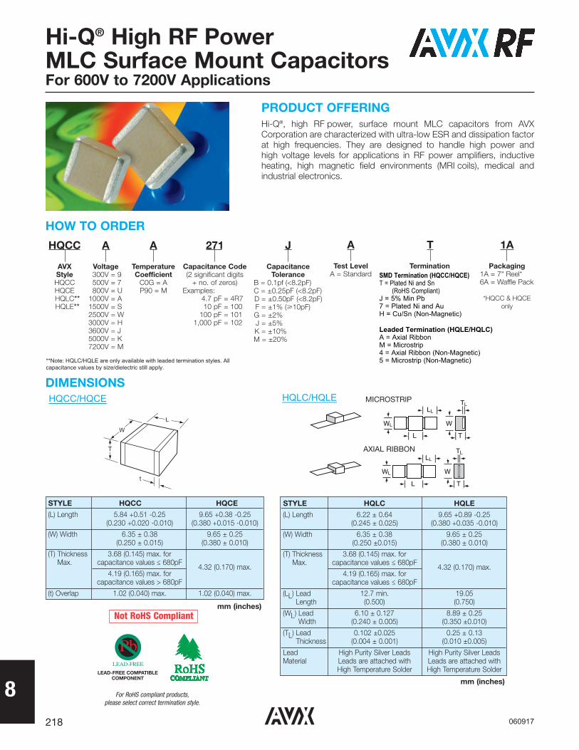
PRODUCT OFFERINGHi-Q®, high RF power, surface mount MLC capacitors from AVXCorporation are characterized with ultra-low ESR and dissipation factorat high frequencies. They are designed to handle high power and high voltage levels for applications in RF power amplifiers, inductiveheating, high magnetic field environments (MRI coils), medical andindustrial electronics.
HOW TO ORDER
STYLE HQCC HQCE
(L) Length 5.84 +0.51 -0.25 9.65 +0.38 -0.25(0.230 +0.020 -0.010) (0.380 +0.015 -0.010)
(W) Width 6.35 ± 0.38 9.65 ± 0.25(0.250 ± 0.015) (0.380 ± 0.010)
(T) Thickness 3.68 (0.145) max. for Max. capacitance values ≤ 680pF
4.32 (0.170) max.4.19 (0.165) max. for
capacitance values > 680pF
(t) Overlap 1.02 (0.040) max. 1.02 (0.040) max.
DIMENSIONS
L
W
T
t
HQCC
AVXStyleHQCCHQCEHQLC**HQLE**
A
Voltage300V = 9500V = 7800V = U
1000V = A1500V = S2500V = W3000V = H3600V = J5000V = K7200V = M
A
TemperatureCoefficient
C0G = AP90 = M
271
Capacitance Code(2 significant digits
+ no. of zeros)Examples:
4.7 pF = 4R710 pF = 100
100 pF = 1011,000 pF = 102
J
CapacitanceTolerance
B = 0.1pf (<8.2pF)C = ±0.25pF (<8.2pF)D = ±0.50pF (<8.2pF)F = ±1% (�10pF)G = ±2%J = ±5%K = ±10%M = ±20%
A
Test LevelA = Standard
T
TerminationSMD Termination (HQCC/HQCE)T = Plated Ni and Sn
(RoHS Compliant)J = 5% Min Pb7 = Plated Ni and AuH = Cu/Sn (Non-Magnetic)
Leaded Termination (HQLE/HQLC)A = Axial RibbonM = Microstrip4 = Axial Ribbon (Non-Magnetic) 5 = Microstrip (Non-Magnetic)
1A
Packaging1A = 7" Reel*6A = Waffle Pack
*HQCC & HQCEonly
STYLE HQLC HQLE
(L) Length 6.22 ± 0.64 9.65 +0.89 -0.25 (0.245 ± 0.025) (0.380 +0.035 -0.010)
(W) Width 6.35 ± 0.38 9.65 ± 0.25 (0.250 ±0.015) (0.380 ± 0.010)
(T) Thickness 3.68 (0.145) max. forMax. capacitance values ≤ 680pF
4.32 (0.170) max.4.19 (0.165) max. for
capacitance values ≤ 680pF
(LL) Lead 12.7 min. 19.05Length (0.500) (0.750)
(WL) Lead 6.10 ± 0.127 8.89 ± 0.25Width (0.240 ± 0.005) (0.350 ±0.010)
(TL) Lead 0.102 ±0.025 0.25 ± 0.13Thickness (0.004 ± 0.001) (0.010 ±0.005)
Lead High Purity Silver Leads High Purity Silver LeadsMaterial Leads are attached with Leads are attached with
High Temperature Solder High Temperature Solder
WL W
L T
LL
TL
WL W
L T
LL
TL
MICROSTRIP
AXIAL RIBBON
Not RoHS Compliant
LEAD-FREE COMPATIBLECOMPONENT
For RoHS compliant products, please select correct termination style.
mm (inches)
mm (inches)
**Note: HQLC/HQLE are only available with leaded termination styles. All capacitance values by size/dielectric still apply.
HQCC/HQCE HQLC/HQLE
8219
Hi-Q® High RF Power MLC Surface Mount Capacitors For 600V to 7200V Applications
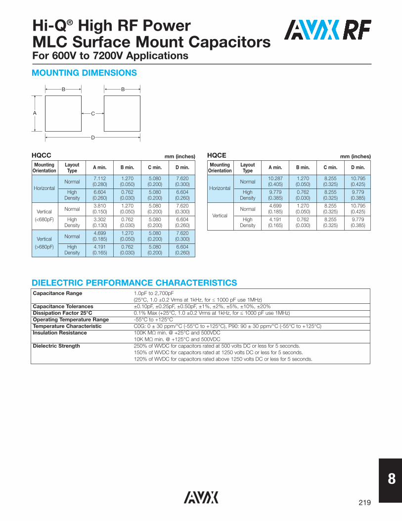
Capacitance Range 1.0pF to 2,700pF(25°C, 1.0 ±0.2 Vrms at 1kHz, for ≤ 1000 pF use 1MHz)
Capacitance Tolerances ±0.10pF, ±0.25pF, ±0.50pF, ±1%, ±2%, ±5%, ±10%, ±20%Dissipation Factor 25°C 0.1% Max (+25°C, 1.0 ±0.2 Vrms at 1kHz, for ≤ 1000 pF use 1MHz)Operating Temperature Range -55°C to +125°CTemperature Characteristic C0G: 0 ± 30 ppm/°C (-55°C to +125°C), P90: 90 ± 30 ppm/°C (-55°C to +125°C)Insulation Resistance 100K MΩ min. @ +25°C and 500VDC
10K MΩ min. @ +125°C and 500VDCDielectric Strength 250% of WVDC for capacitors rated at 500 volts DC or less for 5 seconds.
150% of WVDC for capacitors rated at 1250 volts DC or less for 5 seconds.120% of WVDC for capacitors rated above 1250 volts DC or less for 5 seconds.
DIELECTRIC PERFORMANCE CHARACTERISTICS
MOUNTING DIMENSIONS
Mounting Layout A min. B min. C min. D min.Orientation Type
Normal7.112 1.270 5.080 7.620
Horizontal(0.280) (0.050) (0.200) (0.300)
High 6.604 0.762 5.080 6.604Density (0.260) (0.030) (0.200) (0.260)
Normal3.810 1.270 5.080 7.620
Vertical (0.150) (0.050) (0.200) (0.300)
(<680pF) High 3.302 0.762 5.080 6.604Density (0.130) (0.030) (0.200) (0.260)
Normal4.699 1.270 5.080 7.620
Vertical (0.185) (0.050) (0.200) (0.300)
(>680pF) High 4.191 0.762 5.080 6.604Density (0.165) (0.030) (0.200) (0.260)
B
A
D
C
B
Mounting Layout A min. B min. C min. D min.Orientation Type
Normal10.287 1.270 8.255 10.795
Horizontal(0.405) (0.050) (0.325) (0.425)
High 9.779 0.762 8.255 9.779Density (0.385) (0.030) (0.325) (0.385)
Normal4.699 1.270 8.255 10.795
Vertical(0.185) (0.050) (0.325) (0.425)
High 4.191 0.762 8.255 9.779Density (0.165) (0.030) (0.325) (0.385)
HQCC HQCEmm (inches) mm (inches)
8220
Hi-Q® High RF Power MLC Surface Mount Capacitors For 600V to 7200V Applications
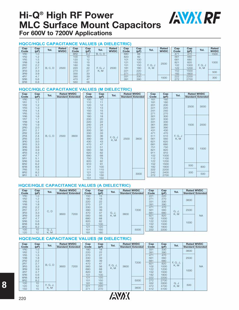
HQCE/HQLE CAPACITANCE VALUES (A DIELECTRIC)Cap Cap
Tol.Rated WVDC
Code (pF) Standard Extended1R0 1.01R2 1.21R5 1.51R8 1.82R2 2.22R7 2.7 C, D3R3 3.3 3600 72003R9 3.94R7 4.75R6 5.66R8 6.88R2 8.2100 10 G, J,120 12 K, M
Cap CapTol.
Rated WVDCCode (pF) Standard Extended150 15180 18220 22270 27330 33390 39 7200470 47 G, J, 3600560 56 K, M680 68820 82101 100121 120151 150 5000181 180
Cap CapTol.
Rated WVDCCode (pF) Standard Extended221 220271 270 3600331 330391 390471 470561 560 G, J, 2500681 680 K, M821 820 NA102 1000122 1200 1000152 1500182 1800222 2200
HQCE/HQLE CAPACITANCE VALUES (M DIELECTRIC)Cap Cap
Tol.Rated WVDC
Code (pF) Standard Extended1R0 1.01R2 1.21R5 1.51R8 1.82R2 2.22R7 2.7 B, C, D3R3 3.3 3600 72003R9 3.94R7 4.75R6 5.66R8 6.88R2 8.2100 10
F, G, J,120 12K, M150 15
Cap CapTol.
Rated WVDCCode (pF) Standard Extended180 18220 22270 27330 33390 39
7200470 47F, G, J,560 56K, M
3600680 68820 82101 100121 120151 150 5000181 180221 220
3600271 270
Cap CapTol.
Rated WVDCCode (pF) Standard Extended331 330 3600391 390471 470561 560 2500681 680
F, G, J,821 820K, M102 1000 NA
122 1200 1000152 1500182 1800222 2200272 2700332 3300 G, J
500472 4700 K, M512 5100
HQCC/HQLC CAPACITANCE VALUES (A DIELECTRIC)Cap Cap
Tol.Rated
Code (pF) WVDC1R0 1.01R2 1.21R5 1.51R8 1.82R2 2.22R7 2.7 B, C, D 25003R3 3.33R9 3.94R7 4.75R6 5.66R8 6.8
Cap CapTol.
RatedCode (pF) WVDC8R2 8.2 B, C, D100 10120 12150 15180 18220 22 F, G, J 2500270 27 K, M330 33390 39470 47560 56
Cap CapTol.
RatedCode (pF) WVDC680 68820 82101 100121 120 2500151 150 F, G, J181 180 K, M221 220271 270331 330 1500391 390
Cap CapTol.
RatedCode (pF) WVDC471 470 1500561 560681 680821 820 1000102 1000 F, G, J122 1200 K, M152 1500 500182 1800222 2200 300272 2700
HQCC/HQLC CAPACITANCE VALUES (M DIELECTRIC)Cap Cap
Tol.Rated WVDC
Code (pF) Standard Extended1R0 1.01R1 1.11R2 1.21R3 1.31R4 1.41R5 1.51R6 1.61R7 1.71R8 1.81R9 1.92R0 2.02R1 2.12R2 2.22R4 2.4 B, C, D 2500 36002R5 2.53R0 3.03R3 3.33R6 3.63R9 3.94R3 4.34R7 4.75R1 5.15R6 5.66R2 6.26R8 6.87R5 7.58R2 8.29R1 9.1
Cap CapTol.
Rated WVDCCode (pF) Standard Extended100 10110 11120 12130 13150 15160 16180 18200 20220 22240 24270 27300 30330 33360 36 F, G, J390 39 K, M 2500 3600430 43470 47510 51560 56620 62680 68750 75820 82910 91101 100111 110121 120 3000131 130151 150
Cap CapTol.
Rated WVDCCode (pF) Standard Extended161 160181 180201 200 2500 3000221 220241 240271 270301 300331 330331 330361 360 1500 2000391 390431 430471 470511 510 F, G, J561 560 K, M621 620681 680751 750 1000 1500821 820911 910102 1000112 1100122 1200152 1500 500182 1800 800222 2200242 2400 300 500272 2700
8221
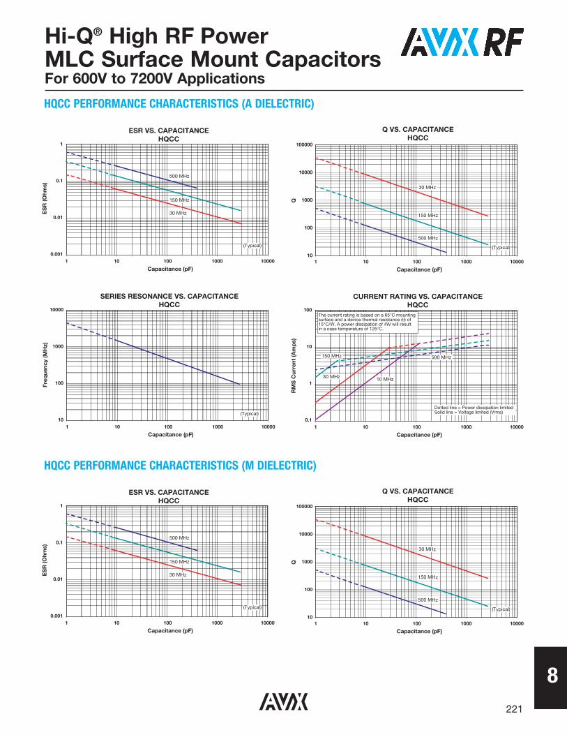
Q VS. CAPACITANCEHQCC
100000
10000
1000
100
101 10 100 1000 10000
Capacitance (pF)
Q
30 MHz
150 MHz
500 MHz
(Typical)
CURRENT RATING VS. CAPACITANCEHQCC
100
10
1
0.11 10 100 1000 10000
Capacitance (pF)
RM
S C
urre
nt (A
mp
s)
150 MHz
30 MHz
Dotted line = Power dissipation limitedSolid line = Voltage limited (Vrms)
500 MHz
10 MHz
The current rating is based on a 65°C mountingsurface and a device thermal resistance (�) of15°C/W. A power dissipation of 4W will resultin a case temperature of 125°C.
SERIES RESONANCE VS. CAPACITANCEHQCC
10000
1000
100
101 10 100 1000 10000
Capacitance (pF)
Freq
uenc
y (M
Hz)
(Typical)
ESR VS. CAPACITANCEHQCC
1
0.1
0.01
0.0011 10 100 1000 10000
Capacitance (pF)
ES
R (O
hms)
150 MHz
30 MHz
(Typical)
500 MHz
HQCC PERFORMANCE CHARACTERISTICS (A DIELECTRIC)
Q VS. CAPACITANCEHQCC
100000
10000
1000
100
101 10 100 1000 10000
Capacitance (pF)
Q
30 MHz
150 MHz
500 MHz
(Typical)
ESR VS. CAPACITANCEHQCC
1
0.1
0.01
0.0011 10 100 1000 10000
Capacitance (pF)
ES
R (O
hms)
150 MHz
30 MHz
(Typical)
500 MHz
HQCC PERFORMANCE CHARACTERISTICS (M DIELECTRIC)
Hi-Q® High RF Power MLC Surface Mount Capacitors For 600V to 7200V Applications

8222
Hi-Q® High RF Power MLC Surface Mount Capacitors For 600V to 7200V Applications
Q VS. CAPACITANCEHQCE
100000
10000
1000
1001 10 100 1000
Capacitance (pF)(1.0 pF to 400 pF)
Q
30 MHz
(Typical)
ESR VS. CAPACITANCEHQCE
1
0.1
0.011 10 100 1000
Capacitance (pF)(1.0 pF to 400 pF)
ES
R (O
hms)
30 MHz
(Typical)
HQCE PERFORMANCE CHARACTERISTICS (A DIELECTRIC)
CURRENT RATING VS. CAPACITANCEHQCC
100
10
1
0.11 10 100 1000 10000
Capacitance (pF)
RM
S C
urre
nt (A
mp
s)
150 MHz
30 MHz
Dotted line = Power dissipation limitedSolid line = Voltage limited (Vrms)
500 MHz
10 MHz
The current rating is based on a 65°C mountingsurface and a device thermal resistance (�) of15°C/W. A power dissipation of 4W will resultin a case temperature of 125°C.
SERIES RESONANCE VS. CAPACITANCEHQCC
10000
1000
100
101 10 100 1000 10000
Capacitance (pF)
Freq
uenc
y (M
Hz)
(Typical)
Q VS. CAPACITANCEHQCE
1000
100
10100 1000 10000
Capacitance (pF)(430 pF to 2200 pF)
Q
30 MHz
(Typical)
ESR VS. CAPACITANCEHQCE
0.1
0.01
0.001100 1000 10000
Capacitance (pF)(430 pF to 2200 pF)
ES
R (O
hms) 30 MHz
(Typical)
8223
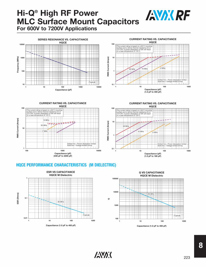
Hi-Q® High RF Power MLC Surface Mount Capacitors For 600V to 7200V Applications
CURRENT RATING VS. CAPACITANCEHQCE
100
10
1
0.11 10 100 1000
Capacitance (pF)(1.0 pF to 400 pF)
RM
S C
urre
nt (A
mp
s)
2 MHz30 MHz
Dotted line = Power dissipation limitedSolid line = Voltage limited (Vrms)
10 MHz
The current rating is based on a 65°C mountingsurface and a device thermal resistance (�) of12°C/W. A power dissipation of 5W will resultin a case temperature of 125°C.
SERIES RESONANCE VS. CAPACITANCEHQCE
10000
1000
100
101 10 100 1000 10000
Capacitance (pF)
Freq
uenc
y (M
Hz)
(Typical)
CURRENT RATING VS. CAPACITANCEHQCE
100
10
1
0.11 10 100 1000
Capacitance (pF)(1.0 pF to 180 pF)
RM
S C
urre
nt (A
mp
s)
2 MHz
30 MHz
Dotted line = Power dissipation limitedSolid line = Voltage limited (Vrms)
10 MHz
The current rating is based on a 65°C mountingsurface and a device thermal resistance (�) of12°C/W. A power dissipation of 5W will resultin a case temperature of 125°C.
CURRENT RATING VS. CAPACITANCEHQCE
100
10
1100 1000 10000
Capacitance (pF)(430 pF to 2200 pF)
RM
S C
urre
nt (A
mp
s)
2 MHz
30 MHz
Dotted line = Power dissipation limitedSolid line = Voltage limited (Vrms)
10 MHz
The current rating is based on a 65°C mountingsurface and a device thermal resistance (�) of12°C/W. A power dissipation of 5W will resultin a case temperature of 125°C.
HQCE PERFORMANCE CHARACTERISTICS (M DIELECTRIC)
Q VS CAPACITANCEHQCE M Dielectric
100000
10000
1000
1001 10 100 1000
Capacitance (1.0 pF to 400 pF)
Q
30 MHz
(Typical)
ESR VS CAPACITANCEHQCE M Dielectric
1
0.1
0.011 10 100 1000
Capacitance (1.0 pF to 400 pF)
ES
R (O
hms)
30 MHz
(Typical)