Embed Size (px)
Citation preview

Rev. (0) - 2012
QualityManagement System
ISO 9001 : 2008Certi�cate No.: QS-5519HH
Enviromental Management System
ISO 14001 : 2004Certi�cate No : 12 104 30334 TMS
Safety Management System
BS OHSAS 18001 : 2007Certi�cate No : 12 116 30334 TMS03502825
Carrier is committed to continuously improving its products according to national and international standards to ensure the highest quality and reliability standards, and to meet market regulations and requirements.
All specifications subject to change without prior notice according to Carrier policy of continuous development.
INSTALLATION MANUAL
Hi Wall Split Air Conditioners53KHRT 12-18-24
Cool Only
220-240V ~, 50HzR22

TABLE OF CONTENTS
PAGE NO. 1. GENERAL NOTES TO INSTALLER 1 2. PRECAUTIONS BEFORE INSTALLATION 2 3. SPLIT SYSTEM DESCRIPTION 3 4. MODELS 4 5. OPERATING LIMITS 4 6. DIMENSIONS AND WEIGHT OF INDOOR UNIT 5 7. DIMENSIONS AND WEIGHT OF OUTDOOR UNIT 5 8. SELECTING INSTALLATION LOCATION OF INDOOR UNIT 6 9. SELECTING INSTALLATION LOCATION OF OUTDOOR UNIT 8
10. INSTALLATION LOCATION – CHECK LIST 12 11. INSTALLTION ACCESSORIES 13 12. INSTALLATION CHART 15 13. INDOOR UNIT INSTALLATION
12.1 PREPARING UNIT BEFORE INSTALLATION 16 12.2 INSTALLATION STEPS 18
14. REMOTE CONTROL INSTALLATION 21 15. OUTDOOR UNIT INSTALLATION
15.1 PREPARING UNIT BEFORE INSTALLATION 22 15.2 INSTALLATION STEPS 22
16. CONNECTING REFRIGERANT PIPING LINES 23 17. CONNECTING CONDENSATE DRAIN LINE 38 18. CONNECTING ELECTRICAL WIRING 40 19. FINISHING INSTALLATION 44 20. TEST RUNNING 45 21. ADJUSTING SUPPY AIR DIRECTION 47 22. AFTER INSTALLATION CHECK LIST 49 23. SELF DIAGNOSTIC FUNCTION FOR MALFUNCTIONS DETECTION 51

1
1. GENERAL NOTES TO INSTALLER Split room air conditioner has been carefully designed and manufactured under strict Quality Control conditions. Therefore you are completely responsible for proper installation completion and operation of the air conditioner. Carefully read the manual carefully before proceeding with the installation to ensure correct installation. This manual describes installation instructions to help ensure trouble free operation and extended life of the air conditioner. Make sure all accessory parts are with the system before beginning installation.
You will need the following tools for installation: 1. Standard screwdriver 10. Flaring tool set 2. Phillips head screw driver 11. Pipe bender 3. Electric drill, Hole core drill 12. Hexagonal wrench ( 4mm ) 4. Measure tape 13. Torque wrench 5. Water level gauge 14. Vacuum pump 6. Pipe clamp 15. Gas leak detector 7. Pipe cutter 16. Gauge manifold 8. Spanner ( half union ) 17. Thermometer 9. Reamer 18. Electrical millimeter
19. Measuring tape
After completion of installation, perform a run test and give the customer full instructions on the correct operation of the air conditioner including:
• Turning the unit on and off. • Removal and cleaning of the air filters. • Functions of the remote control. • Re-installation of air filters after cleaning
Leave the owner manual with the customer so that it can to be used during operation of the air conditioner. Leave the installation manual with the customer so that it can be used for any service and maintenance operations.
Advise the customer to the tips of energy saving while operating the air conditioner as mentioned in the owner’s manual.

2
2. PRECAUTIONS BEFORE INSTALLATION
SAFETY PRECAUTIONS
• Installation and maintenance of air conditioning equipment can be hazardous due to system pressures, electrical components and rotating parts.
• The installation and maintenance of the air conditioner must be carried out by trained and
qualified technicians from Carrier or one of Carrier authorized dealers.
• After unpacking, Please check carefully for possible damage the indoor and outdoor units of the air conditioner.
• Before undertaking any work on the indoor and outdoor units of the air conditioner, make sure
to disconnect the power supply.
WARNING • This installation manual describes the installation procedures of split room air conditioner
consisting of an outdoor unit and an indoor unit manufactured by Carrier. • The installation of air conditioner must be according to applicable national installation
standards. • During installation, Proceed first with refrigerant connections between indoor and outdoor
units, and only then make the electrical connections. Similarly, when disassembling, disconnect the electrical wiring first and only then open refrigerant connections.
What is not covered in our warranty?
1- Failure due to wrong electrical connections between the electrical power supply and circuit breaker of air conditioner leading to fire due to short-circuiting. As these electrical connections are owner’s responsibility.
2- Failure due to Misuse, Abusing, overloading, negligence of air filters cleaning and negligence of instructions included in the owner’s manual.
3- Failure due to Accident / Weather Natural catastrophe, accident due to bad weather (Hail Storm, Sand Storm, lightning, Flooding, Acid Rain and Air Borne fallout, etc).
4- Failure due to damages during transport done through the owner.
5- Failure due to any modifications in the product done through the owner.
6- Failure due to Installation or Service and Maintenance or repair works done through the owner.
7- Product normal sound ( refrigerant – moving parts – plastic parts )
8- Inconvenience or commercial loss is not covered.
The decision of Carrier in ascertaining the same will be final. Any such repairs will be carried - out at the expense of the owner ( purchaser ).
!

3
3. SPLIT SYSTEM DESCRIPTION
Split System Models 53KHRT12 & 53KHRT18
Split System Model 53KHRT24
1: Remote control signal receiver. 2: LCD Display panel 3: Panel frame 4: Chassis 5: Front panel 6: Horizontal supply air louver 7: Vertical supply air louvers 8: Air filters 9: Manual control button 10: Power cord 11: Inter-connecting refrigerant piping and electrical
cables between indoor and outdoor units. 12: Drain hose
13: Wireless remote control
Indoor Unit 3 8 Air Inlet 4
5
Outdoor Unit
6 9
10
12
13
Air outlet
11
7
1 2
Indoor Unit 3 8 Air Inlet 4
5
Outdoor Unit
6 9
10
12
13
Air outlet
11
7
1 2

4
4. MODELS
Cool only
System Model
Indoor Unit Model
Outdoor Unit Model
53KHRT12-708 42KHRT12-708 38KHRT12-708 53KHRT18-708 42KHRT18-708 38KHRT18-708 53KHRT24-708 42KHRT24-708 38KHRT24-708
NOTES:
53 = Split System 42 = Indoor Unit 38 = Outdoor Unit K = Cool Only H = Hi Wall System R = Crystal Series T = High Ambient 12 = System Size 7 = Nominal Power Supply 220-240V ~ 50Hz 1Ph 0 = Wireless Remote Control 8 = Miraco – Carrier
5. OPERATING LIMITS
COOLING
Difference Dry Bulb Temp. C°
Wet Bulb Temp. C°
Indoor temperature Maximum Minimum
32 21
23 15
Outdoor temperature Maximum Minimum
52 21
- -
MAIN POWER SUPPLY
Nominal 220-240V ~ 50Hz 1Ph
Min. Voltage 198
Max. Voltage 254
NOTE: * When the system operates above or below these limits for a long time, system diagnostics
may detect a malfunction and the system will not operate properly.

5
860
665
665
350
384
575
371
350
6. DIMENSIONS AND WEIGHT OF INDOOR UNIT
DIMENSIONS (mm)
Model Dimensions Weight
A B C
42KHRT12 790 275 190 8.5
42KHRT18 940 275 198 12
42KHRT24 1030 313 221 17
7. DIMENSIONS AND WEIGHT OF OUTDOOR UNIT
DIMENSIONS (mm)
Model
Mounting Dimensions
(mm)
Unit Dimensions
(mm) Weight
A B C D E
38KHRT12 549 276 780 540 250 33
38KHRT18 530 290 760 590 285 39.5
Weight
Model Kg
38KHRT24 58.7
A C
B
Kg
Kg
C
D
B
A
E
Kg

6
8. SELECTING INSTALLATION LOCATION OF INDOOR UNIT
8.1 CONSIDERATIONS OF SELECTING INSTALLATION LOCATION
Select installation location which allows minimum clearances for free air circulation and easy accessibility for service and maintenance.
• Select outlet location of piping from indoor unit which allows easy access to the ends of refrigerant piping lines to facilitate refrigerant leak testing and to facilitate service and maintenance.
• Select installation location so that the
wall hole required to pass the outlet refrigerant piping lines, electrical cables and condensate drain line from indoor unit can be in one of the following Four outlet locations as indicated by (1), (2), (3) and (4)
Avoid installation location which can lead to excessive length of refrigerant piping lines between indoor and outdoor units
Avoid installation location which can lead to excessive height difference between indoor and outdoor units
Dimensions (mm)
Back right outlet location
Back left outlet location
Right side outlet location
Left side outlet location

SECO
STd
ELECTING
ONSIDERA
Select instaThe wall stdeformatio
INSTALLAATIONS O
allation loctructure shon, rupture
1900 mm or more
ATION LOCOF SELEC
cation whihould be ste or vibrati
ob
CATION OFCTING INST
ich has flatrong enouon during
bstacle
7
F INDOORTALLATIO
SelunitunifAvolow
Avosubper
Avoheaof t
Avoobscurthatthe
Avoenv
Avoenvwavweld
at wall surfugh to car operation
R UNIT (CoON LOCAT
ect installat to deliveformly air-oid installa
w a position
oid installabjected to rformance
oid installaat sources the unit.
oid installastacles sucrtains, furnt may affe unit.
oid an instavironment w
oid an instavironment aves generaders and m
face to allorry the unitn.
nt.) TION (Con
ation locatr air to all -conditionation of then.
ation locatdirect sun of the unit
ation locat that may a
ation locatch as curta
niture nearct air flow
allation locwith oil va
allation locaffected by
ated as fromedical eq
ow easy ant weight an
nt.)
tion which of the spaed. e indoor u
tion which light that t
tion which affect perf
tion whereains and sr the air inl and perfo
cation, whapors.
cation whiy high freqm radio eq
quipment’s
nd safe insnd avoid
h permit thace to be
nit at too
is may affec
is near toformance
e there are such as let or outle
ormance of
hich has an
ich has anquency quipment’ss.
stallation.
e
ct
et f
n
s

8
9. SELECTING INSTALLATION LOCATION OF OUTOOR UNIT 9.1 INSTALLATION LOCATIONS
The outdoor unit can be installed in any outside location, on a wall, on a roof or on a ground level.
9.2 CONSIDERATIONS FOR SELECTING INSTALLATION LOCATIONS
Avoid installation location which can lead to excessive distance between outdoor and indoor units to avoid alteration on system cooling performance.
Avoid installation location which can lead to excessive height difference between indoor and outdoor units to avoid alteration on system cooling performance.
Avoid installation location which can lead to unnecessary turns and bends in the refrigerant piping lines connecting outdoor unit with indoor unit.
Avoid installation location where there are obstacles near the air outlet or inlet that may affect air flow and performance of the unit
Avoid multiple unit installation with units facing each other and blowing discharged air into each other.

9
SELECTING INSTALLATION LOCATION OF OUTOOR UNIT (Cont.)
CONSIDERATIONS FOR SELECTING INSTALLATION LOCATION (Cont.)
Select the installation location of outdoor unit which is able to support operating weight of outdoor unit, and not cause vibration.
Select the installation location of outdoor unit which is far away from the direct sunlight.
Select the installation location of outdoor unit which is far away from heat sources, steam or flammable gas.
Select the installation location of outdoor unit which is free of dust or any material, which can cause clogging of condenser coil. When installing unit on the ground, select a location not subjected to flooding.
Avoid installation location which is full of oil vapors which may result in malfunction.
Avoid installation location which is full of sulfuric gas which may result in malfunction.
Select installation location where the operation noise and discharged air are not disruptive to your neighbors.
When the installation is made on the rooftop or other places subject to strong wind :
When the outdoor unit is to be installed on the rooftop or at the places where there are no other buildings around. it is required to avoid the strong wind from blowing directly into the air outlet of the outdoor unit so as to prevent the negative impacts on cooling performance due to insufficient airflow of the outdoor unit heat exchanger and to prevent from faulty performances.
When there are walls in the vicinity, the air outlet should face the wall and keep a space of 500mm from the wall.
When the air outlet is affected by the strong wind, the installation position should be changed so as to make the air outlet at a straight angle from the wind direction.

10
SELECTING INSTALLATION LOCATION OF OUTOOR UNIT (Cont.)
9.3 MINIMUM CLEARANCES WHEN SELECTING INSTALLATION LOCATION FOR SINGLE OUTDOOR UNIT INSTALLATION
Obstacle at unit front ( air outlet )
Select installation location which allows the minimum clearances shown in the figures for free air circulation and easy accessibility for service and maintenance :
The front of outdoor unit ( air outlet ) should be away from any obstacle by 500 mm or more to ensure free air circulation.
The back of outdoor unit ( air inlet )
should be away from any obstacle by 160 mm or more. This distance is built in the design of wall support to ensure free air circulation.
The left side of outdoor unit
should by away from any obstacle by 400 mm or more to ensure easy access to refrigerant and electrical connections.
The right side of outdoor unit ( air inlet )
should be away from any obstacle by 250 mm or more to ensure free air circulation.
The top side of outdoor unit
should be away from any obstacle by 400 mm or more to ensure easy access to the electrical components, motor and fan.
Obstacle at unit front ( air outlet ) & Obstacle at unit back ( air inlet )
Obstacle at unit front ( air outlet ) & Obstacle at unit top
Obstacle at unit back ( air inlet )
Obstacle at unit back ( air inlet ) & Obstacle at unit top
Obstacle at unit back ( air inlet ) & Obstacle at unit right and left sides
500 mm or more
160 mm or more
1000 mm or more
400 mm or more 1000 mm
or more
160 mm or more
400mm or more 160mm
or more
160 mm or more
400 mm or more
250 mm or more

11
SELECTING INSTALLATION LOCATION OF OUTOOR UNIT (Cont.)
9.4 MINIMUM CLEARANCES WHEN SELECTING INSTALLATION LOCATION FOR SERIAL INSTALLATION OF MORE THAN ONE OUTDOOR UNIT
Obstacle at unit front ( air outlet )
Select installation location which allows the minimum clearances shown in the figures for free air circulation and easy accessibility for service and maintenance :
The front of outdoor unit ( air outlet ) should be away from any obstacle by 500 mm or more to ensure free air circulation.
The back of outdoor unit ( air inlet )
should be away from any obstacle by 160 mm or more. This distance is built in the design of wall support to ensure free air circulation.
The left side of outdoor unit
should by away from any obstacle by 400 mm or more to ensure easy access to refrigerant and electrical connections.
The right side of outdoor unit ( air inlet )
should be away from any obstacle by 250 mm or more to ensure free air circulation.
The top side of outdoor unit
should be away from any obstacle by 400 mm or more to ensure easy access to the electrical components, motor and fan.
Obstacle at unit front ( air outlet ) & Obstacle at unit back ( air inlet )
Obstacle at unit back ( air inlet )
Obstacle at unit back ( air inlet ) & Obstacle at right and left sides
1000 mm or more
160 mm or more
1000 mm or more
400 mm or more
400 mm or more
160 mm or more
400 mm or more
400 mm or more
400 mm or more
400 mm or more
400 mm or more
250 mm or more
160 mm or more

12
10. INSTALLATION LOCATION CHECK LIST
(A) INDOOR UNIT
- The installation location is close to the outdoor unit
- The wall hole (required to pass refrigerant piping, electrical cables and drain line) is properly made as per installation required.
- The installation location permit the unit to deliver air to all of the space to be air-conditioned
- The installation location is far away from any sunlight
- The installation location is far away from any heat sources
- The installation location avoid obstructions, which affect motion of supply and/or return air to the unit
- The installation location permit free service space around the unit right, left, front back and top
(B) OUTDOOR UNIT
- The electrical power supply is close to the outdoor unit
- The installation location is close to the indoor unit
- The installation location is able to support operating weight of outdoor unit
- The installation location is far away from any sunlight
- The installation location is free of dust or any material, which can cause clogging of outdoor coil
- The installation location allow sufficient space for air circulation around the unit
- The installation location allow sufficient space for service and maintenance around the unit
- The installation location is selected so that the operation noise and discharge air do not disturb the neighbors
(C) REFRIGERANT PIPING LINES BETWEEN INDOOR AND OUTDOOR UNITS
- The excessive length of refrigerant piping lines is avoided
- The excessive height between indoor and outdoor units is avoided
- The excessive number of turns and bends in the refrigerant piping lines is avoided

13
11. INSTALLATION ACCESSORIES 11.1 STANDARD INSTALLATION ACCESSORIES SUPPLIED FROM THE FACTORY
DESCREPTION SHAPE QTY USAGE Battery 1.5 volt size AAA alkaline type
2 To operate the wireless remote control
Wireless remote control
1 To operate the air conditioner
Owner manual
1 To illustrate control functions of operation
Installation Manual 1 To illustrate installation instructions.
Wall hang bracket
1 For indoor unit installation on the wall.
Wall support for outdoor unit ( Only for domestic market )
1 To mount outdoor unit on the wall
Floor support for outdoor unit ( Only for domestic market )
1 To mount outdoor unit on the ground
or floor
Insulated refrigerant piping lines with flare nuts of length 3 meter ( Only for domestic market )
1
To connect refrigerant between outdoor and indoor units and refrigerant piping lines
11.2 STANDARD INSTALLATION ACCESSORIES SUPPLIED FROM THE FACTORY
( Only for export markets )
DESCREPTION SHAPE QTY USAGE
Flare nuts ( 3/8” & 1/4” ) supplied with outdoor unit 38KHRT12
1 + 1 To be mounted on the refrigerant piping lines before being connected to the outdoor unit.
Flare nuts ( 1/2” & 1/4" ) supplied with outdoor unit 38KHRT18
1 + 1 To be mounted on the refrigerant piping lines before being connected to the outdoor unit.
Flare nuts ( 1/2” & 1/4” ) supplied with outdoor unit 38KHRT24
1 + 1
To be mounted on the refrigerant piping lines before being connected to the outdoor unit.
Flare nuts ( 3/8” & 1/4” ) supplied with indoor unit 42KHRT12
1 + 1 To be mounted on the refrigerant piping lines before being connected to the indoor unit.
Flare nuts ( 1/2” & 1/4" ) supplied with indoor unit 42KHRT18
1 + 1 To be mounted on the refrigerant piping lines before being connected to the indoor unit.
Flare nuts ( 1/2” & 1/4” ) supplied with indoor unit 42KHRT24
1 + 1
To be mounted on the refrigerant piping lines before being connected to the indoor unit.

14
INSTALLATION ACCESSORIES (Cont.) 11.4 OTHER INSTALLATION ACCESSORIES
Not supplied from the factory but must be used in the installation field to complete installation.
DESCREPTION USAGE
Electrical Connection Cables
To electrically connect the indoor unit, the outdoor unit and circuit breaker
Wall Sleeve ـ Wall Cap ـ Sealer putty ـ
To fill the gap between the wall hole and the lump of refrigerant piping lines, electrical connection cables and condensate drain line.
Finishing tape PVC film To tie together the refrigerant piping lines, electrical connection cables ـand condensate drain line.
.Vinyl tape To stick pipe insulation ـ
.Drain hose ID 16-17mm To remove condensate water, from the indoor unit to the outside ـ
Refrigerant piping lines To connect refrigerant R22 between indoor and outdoor units ـ
Pipe insulation To insulate gas and liquid refrigerant piping lines ـ
- Refrigerant R22 To adjust refrigerant charge for long refrigerant piping lines (more than 3 meter)
- Clamps or saddles To secure the lump of refrigerant piping lines, electrical cables and condensate drain line

15
12. INSTALLATION CHART
1) Installing outdoor unit 5) Connecting refrigerant piping lines
9) Air purging with a vacuum pump
2) Drilling hole thru the wall
6) Connecting condensate drain line
10) Refrigerant leak test
3) Installing indoor unit 7) Connecting electrical wiring
11) Opening service valves
4) Pipes flaring 8) Finishing outer pipe covering
12) Finishing installation
13) Test Running
14) Description of operation
Outdoor unit

16
13. INDOOR UNIT INSTALLATION
13-1 PREPARATION STEPS BEFORE INSTALLATION
STEP (1) :Selecting Wall Hole Location
Back right or Back left piping : In case of passing refrigerant piping lines, electrical cables and condensate drain line behind the unit, drill a hole of 65mm behind the unit in one of the following locations as per the section : Right Side or Left Side Piping : In case of passing refrigerant piping lines, electrical cables and condensate drain line from unit right side or from unit left side, remove the pipe cover form the side panel.
Size 12K
Size 18K
Size 24K
Right rear side refrigerant pipe hole ø 65
45
90
120 mm or more to wall
Left rear side refrigerant pipe hole ø 65
120 mm or more to wall
40
40 780
Indoor unit outline Installation plate 150mm or more to ceiling
270
Indoor unit outline Installation plate 150mm or more to ceiling
120 mm or more to wall 120 mm or
more to wall
920
45
270
70
70
Left rear side refrigerant pipe hole ø 65
Right rear side refrigerant pipe hole ø 65
150mm or more to ceiling Hooked Part
120 mm or more to wall 120 mm or
more to wall
380 380 138 1036
315 130
Indoor unit outline
22
130
50

IND
SB
S
S
DOOR UNIT
PREPAR
Step (2): Before maki
• The wal• If the wa
be unsta• No stud• No elect• Drill a h
and elecThe walor (2). When mdownwaentrance
Step (3):
• Meathe oshor
Step (4):
• Afteholerefrithro
T INSTALLRATION S
Making W
ng a hole, c
l is flat and all is not flatable and cons or pipes atrical wiringole of 65 mmctrical cablel hole can b
making wall hard angle, soe and exit ofCutting S
asure the thioutside edgrter than the
Mounting
er making hoe and its widgerant lines
ough the wal
LATION (CSTEPS BEF
Wall Hole Pheck carefu
perpendicut and perpenndensate dr
are directly r or conduits
m to pass thes. e made as r
hole, make so that the hef the hole is
Sleeve For
ckness of the and cut PV
e thickness o
g Sleeve In
ole, a sleevedth to be equs, drain hosell hole.
Cont.) FORE INS
Precautionlly the follow
lar. ndicular, therain can spilrun behind ts are locatedhe refrigeran
required in e
sure to drill eight differes at least 5-1r Wall Hole
he wall fromVC pipe at aof the wall.
nto Wall H
e must be moual to wall the and electri
17
STALLATIO
ns: wing points
e indoor unitll. the spot to bd. nt lines, drai
either locatio
outwards atnce between0 mm. e
m the inside ea slight angl
Hole
ounted into hickness to ical cables
ON (Cont.
:
t can
be cut.
n hose
on (1)
t a n the
edge to e 6mm
wall pass
W Sl
)
Indoor side
Cut
I
Wall leeve
Wall O
t Wall Sleeve
Indoor side Wal
Wall
5-10 mm
Outdoor side
e
Outdoor Sidel

18
INDOOR UNIT INSTALLATION (Cont.)
13-2 INSTALLATION STEPS OF INDOOR UNIT Step (1) : Installing wall hang bracket
• Allow the clearance space around the unit, which permits adequate air circulation, easy access to the unit for easy service and maintenance.
• Fix wall hang bracket on the wall so that it is leveled vertically and horizontally by using five self-tapping screws to fix bracket top. 1 (One) screws to fix bracket mid, 2 (Two) screws to fix bracket bottom, Use a plumb line if necessary to adjust leveling of the wall hang bracket.
Correct installation of the wall hang bracket Incorrect installation of the wall hang bracket
NOTES a. Fasten the wall hang bracket to the wall with at
least 5 (Five) screws ( supplied with unit ). This correct fixation will prevent motion of bracket after fixation, which can cause noisy unit operation.
b. The wall hang bracket must be leveled in both horizontal and vertical directions after fixation without tilting to the right or lift to avoid water dropping from the unit onto the floor. See Fig.
c. Install the wall hang bracket so that three is no gap between it and the wall to avoid vibrations and sound during unit operation.
d. Check that the wall hang bracket does not move. This can cause noise during operation.
See chapter (18):Connecting Electrical Wiring.Step (2): Electrical wiring of indoor unit
Step (3): Form refrigerant piping, drain hose and electrical cables of indoor unit.
• As per the selected location of wall hole, form and tie together with vinyl tape the refrigerant piping, electrical cables and drain hose to form a bundle. The drain hose should be at the bottom of the bundle. Locating the drain hose at the top of the bundle can cause drain pan to overflow inside the indoor unit.
NOTES a. Do not remove the flare nuts from the indoor unit
piping until the piping is ready for connection with refrigerant piping lines.
b. Do not crush or kink the indoor unit piping. Avoid tight bending with a bending radius less than 100 mm.
c. Do not bend the same part of the pipe too often to avoid pipe damage.
d. Bend pipes carefully to avoid flattening or obstructing them if the pipes are bent in correctly, the indoor unit may be unstable on the wall.
e. Carefully arrange pipes so that pipes do not stick out of the wall hang bracket of the indoor unit.
Connective pipe
Pending box
Pipe room
Wrapping belt Drain hose
Connective cable
2
3 1
4
5
6
Indoor Unit
Correct orientation of Installation Plate
19
INSTALLATION OF INDOOR UNIT (Cont.)
INSTALLATION STEPS OF INDOOR UNIT (Cont.)
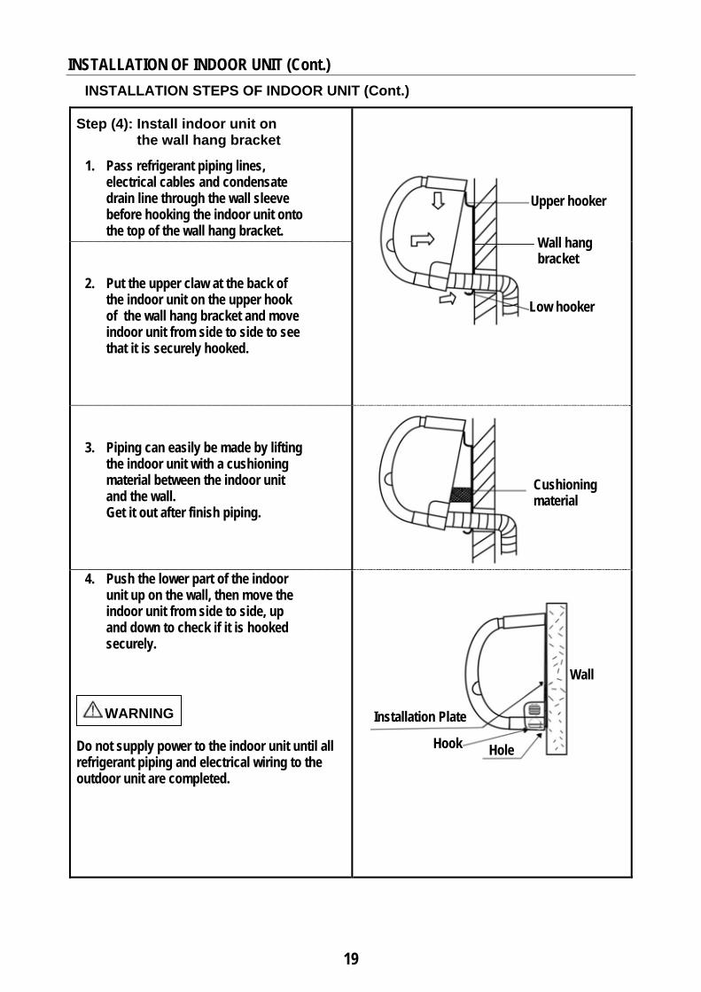
Step (4): Install indoor unit on the wall hang bracket
1. Pass refrigerant piping lines, electrical cables and condensate drain line through the wall sleeve before hooking the indoor unit onto the top of the wall hang bracket.
2. Put the upper claw at the back of the indoor unit on the upper hook of the wall hang bracket and move indoor unit from side to side to see that it is securely hooked.
3. Piping can easily be made by lifting the indoor unit with a cushioning material between the indoor unit and the wall. Get it out after finish piping.
4. Push the lower part of the indoor unit up on the wall, then move the indoor unit from side to side, up and down to check if it is hooked securely.
WARNING
Do not supply power to the indoor unit until all refrigerant piping and electrical wiring to the outdoor unit are completed.
Upper hooker
Low hooker
Cushioning material
Wall hang bracket
Installation Plate
Wall
Hook Hole

20
14. REMOTE CONTROL INSTALLATION
14-1 HOW TO INSERT BATTERIES :
(a) Remove the cover of battery compartment at the back of the remote control by pressing the tab toward outside, in the direction of the arrow.
(c) Press the button (at the front of remote control) with an object not sharp to operate the remote control.
(b) Mount two batteries size AAA 1.5 Volt supplied with the remote control. Then close the cover of the battery component.
Note: During mounting of batteries check battery symbols (+, -) indicated in batteries compartment.
NOTES 1. The remote control uses two alkaline batteries (1.5 Volts) .
2. Do not use old batteries or batteries of different types, as this may cause the remote control to malfunction.
3. If you do not use the remote control for more than a few weeks, please remove the batteries. Other wise battery leakage may damage the remote control.
4. The average battery life during normal use is approximately half a year.
5. Replace the batteries when there is no receiving beep coming from the indoor unit or transmission indicator on the remote control fails to light.
6. Batteries should only be replaced after turning OFF the air conditioner.

21
REMOTE CONTROL INSTALLATION (Cont.) 14-2 INSTRUCTIONS OF USING WIRELESS REMOTE CONTROL 1- The remote control must be directed toward the receiver of indoor unit when pressing the buttons
of the desired functions. An acoustical acknowledgement sound (beep) will indicate that signal has been received.
2- Avoid direct sunlight on the receiver of indoor unit, which may interfere with good signal reception and the air conditioner may not work properly. Draw the curtains to avoid direct sunlight.
3- Avoid obstacles obstructions such as curtains, doors or other materials between the remote control and the receiver of indoor unit to avoid blocking the signals from the remote control to the indoor unit.
4- The maximum operating distance for the remote control is approximately 8 meters.
5- Keep the remote control away from water. Do not let the remote control fall down. 6- Never use objects with sharp point to press the button on the remote control. 7- Prevent any liquid from falling into the remote control. 8- If other electric applications react to the remote control, move these applications.
Remote control
8 meter

a.
W
S(1 (2 (3
Im(1(2(3
FP
15. OUTD
15.1 P Put packe
15.2 W
Wall SuppoSR 1 2 3 4 5 6
teps of wa) Fix back a
by using 22) Fix front a by using 23) Fix top an by using 4
mportant N) Mount sp
2) Tighten n3) Be sure thix wall suppo
Put unit on the
Wall Ins
Detail A
5
6
A
DOOR UNITPREPARAd unit as sho
WALL INSort Parts
Part Right SideLeft Side Back AnglFront & ToNut Spring Wa
all supportangle (item 32 nuts (itemangle (item 42 nuts (itemngle (item 4)4 nuts (item
Notes : ring washer
nut properly hat the final ort into the we wall suppo
stallation
2
4
T INSTALLATION STEown.
STALLATIO
Descriptione
le op Angle
asher t assembly3) with right 5) and 2 sp4) with right 5) and 2 sp) with right s 5) and 4 sp
r before mou with torque appearance
wall rt.
4
3
LATION EPS BEFO
b. Lift unit
ON STEPS
n Qt111288
y t side (item1
pring washert side (item 1
pring washerside (item 1)
pring washer
unting the n wrench wite of assemb
Outdoor Unit
Wall Support
22
ORE INSTAfrom cardboa
S
ty 1 1 1 2 8 8
) and left srs (item 6). 1) and left srs (item 6). ) and left sidrs (item 6).
nut. th tighteningbled wall sup
Put o F
t
1
ALLATIONard.
ide (item 2)
ide (item 2)
de (item 2)
g torque 5.7 pport to be loutdoor unit o
Floor Insta
4 Finalof wa
N
c. Remoremov
Detac remov
Nm to haveeveled and
on the floor s
allation
1 2
2
4
3
l Assembly all support
ove service doving one screh the cable cving one scre
e tight matchsame as fig
support
1
oor (item 2) bew (item 1). clamp by ew.
h. ure.
Outdoor Unit
Floor Support
by

23
16. CONNECTING REFRIGERANT PIPING LINES
16-1 REFRIGERANT CONNECTIONS CHART
(1) Pipes Flaring
(2) Pipes Connections
(3) Air Purging
(4) Leak Check
(5) Pipes Insulation
(6) Opening Valves

24
CONNECTING REFRIGERANT PIPING LINES (Cont.)
16-2 POSSIBLE OUTLET LOCATIONS OF REFRIGERANT PIPING LINES FROM INDOOR UNIT
The refrigerant piping lines can be connected in one of the following four outlet locations:
• Select outlet location of piping from indoor unit which allows easy access to the ends of refrigerant piping lines to facilitate refrigerant leak testing and to facilitate service and maintenance.
NOTES 1. For right side or left side piping, remove the
pipe cover from side panel. • Explain to the client that the pipe cover must
be kept as it may be used when relocate the air conditioner to any other place.
2. For the back right or back left piping, install the piping as shown. Bend the connective pipe to be laid at 43 mm height or less from the wall.
3. Fix the end of the connective pipe.
Indoor Unit Outline Piping
Back right piping
Back left piping
Right side piping
Left side piping
1
2
3
4

CONNEC
16-3 INS
Recomm
TING REFSTRUCTIO
mended
RIGERANTONS OF CO
NRecom
T PIPING LONNECTII
-
-
-
-
--
Not mended
25
LINES (CoNG REFR
Avoid eindoor a
Keep thto avoidperform
Avoid elines be
Keep thto avoidperform
Avoid erefrigerwith bo
Keep thminimucooling
Piping minstallesystems
Piping mbe of re
- Select thto be ins
- All bendsindoor unof refrige
- Do not recouplingready foroutdoor
- The instarun it bet● Do no
at one● When
the piWhen form
- Avoid pip- The mini
less than
nt.) RIGERANT
excessive hand outdo
he height dd alteration
mance.
excessive letween indhe height dd alteration
mance.
excessive nrant pipingth the indo
he number um to avoidg performamust be per accordins practicesmaterials aefrigerant qe pipe diamtalled. s must be nit with ou
erant pipinemove thegs until ther connectiounits. This
aller must tween the ot bend thee place.
n extendingipe by unwming the ppes flatterimum radiu
n 100 mm t
T PIPING L
height diffoor units. difference tn on syste
length of rdoor and odifference tn on syste
number ofg lines durioor and ou of turns ad alterationnce. erformed b
ng to good s. and insulaquality. meters to
considereutdoor unitg lines. protective
e refrigeranon with bos is to keecarefully u indoor ande pipe mor
g the rolledwinding it. pipe. Be caing or kinkus of bendto avoid da
LINES
ference bet
to a strict em cooling
refrigerant outdoor unto a strict
em cooling
f turns anding connecutdoor unitand bends n on syste
by qualifie refrigerat
tion mater
the size of
ed when cot by requir
e caps fromnt piping lioth indoor p piping c
unroll the td outdoor re than thr
d pipe, str areful not tking. ding must namage of p
tween
minimum g
piping its. minimum
g
d bends in ctions ts. to a strict em
d ion
rials must
f system
onnecting red length
m the ines are and
clean. tubing and units.
ree times
raighten
to crush it.
not be piping.
d
.

CONNEC
INSTRUC
TING REFCTIONS OF
Exm
Insulation
RIGERANTF CONNEC
xcessive tubmust be coil
horizontally
n
T PIPING LCTIING RE
bing ed y
CopperPiping
26
LINES (CoEFRIGERA
Wheinsuareaand toge
Whecoilerefrigcoil a The vertioil re
Avoiconnto av
r
nt.) ANT PIPIN
en making ulation anda. Using a t then the inether.
n there is ed horizontgerant is frand toward excessivecally since
eturn to th
d disconnnections afvoid refrige
NG LINES
a bend, thd slides it atube bendnsulation i
excessivetally so tharom the tods the oute tubing me the vertice compres
necting refrfter they herant leaks
(Cont.)
he installeraway fromer makesis replaced
e tubing, it at the flow
op to bottotdoor unit.
must not becal coil affssor.
rigerant pihave been ts.
r cuts the bend the bend d gluing it
must be w of om of the e coiled fects the
iping tightened

CONNEC
16.4 USEThe followiunits where
(A) OUT Slo
(B) OUT• If h
risco
• If hwifirs
(C) OUT An o
facil
Model
53KHRT1253KHRT1853KHRT24
Model
53KHRT1253KHRT1853KHRT24
Model
53KHRT1253KHRT1853KHRT24
CTING REE OF REFRing data refee : L =
H =
TDOOR Up tubing tow
TDOOR Uheight is lesser near the ompressor mheight is moll be at the gst one and s
TDOOR Uoil trap is prlitate oil retu
Meters L H
8 4 20 10 20 10
Outdoor U12K – 18K
Meters L H
8 4 20 10 20 10
Meters L
8 20
4 20
O
EFRIGERRIGERANers to the us= Maximum Maximum
UNIT BELOwards the ou
UNIT ABOVss than or eq Indoor unit
mechanical pore than 4 mgas line neaso on.
UNIT ON THreferred to burn to the co
0 0
nit K
0 0
Outdoor Unit 12K – 18K
Indoor24
Out12
RANT PIPT PIPING se of refrige length of revertical dist
OW INDOOutdoor unit w
VE INDOOqual 4 meter to facilitate parts.
meters, morer to the indo
HE SAME e at the gas
ompressor t
Ind12
r Unit K
tdoor Unit 2K – 18K
27
ING LINELINES rant piping
efrigerant piptance betwe
OR UNIT :with a fall of
OR UNIT :rs, one oil tra oil return to
than one oioor unit and
LEVEL As line at the bto ensure eff
door Unit 2K - 18K
Indoor Un12K – 18
L
ES (Cont.
lines of diamping lines ben outdoor
f at least (6m
ap must be ao the compre
il trap must the followin
S INDOORbase of gas ficiency of c
L
Gas
Indoo24
nit 8K
Indoo24
Oil Trap
L
)
meters equivetween outd and indoor
mm) to (305m
at the gas liessor to ens
exist at the ng one will b
R UNIT: riser near thcompressor
Oil trap
Liquid
r Unit 4K
or Unit 4K
Liquid
Gas
valent to thadoor and indunits.
mm).
ne at the basure efficien
gas line, thebe 4 meters
he Indoor un mechanical
Indo12K
O
at use in door units.
ase of gas ncy of
e first one from the
nit to l parts.
Outdoor Unit18K - 24K
Outdoor Uni24K
oor Unit K – 18K
Outdoor Unit 24K
t
t

28
CONNECTING REFRIGERANT PIPING LINES (Cont.) 16. DIAMETERS AND LENGTHS OF REFRIGERANT PIPING LINES
Model Gas line diameter
Liquid line diameter
Max. Line Length (MT)
53KHRT12 3/8” 1/4” 8
53KHRT18 1/2” 1/4” 20
53KHRT24 1/2” 1/4” 20
16.6 REFRIGERANT CHARGE
(1) The outdoor unit is factory supplied with refrigerant charge for use with refrigerant piping lines of length 3 meters and with added 50 grams for air and moisture purge from the system.
(2) For refrigerant piping lines of length more than 3 meters, add in the field 25 grams of refrigerant
per extra meter more than 3 meters :
Example 1 = For 8 meter lines, refrigerant added = (8-3) x 25 = 125 grams. Example 2 = For 10 meter lines, refrigerant added = (10-3) x 25 = 175 grams.
(3) NOTES
• Refrigerant overcharge may cause a serious trouble of compressor.
• Refrigerant undercharge may cause reduction of system performance.
CONNEC
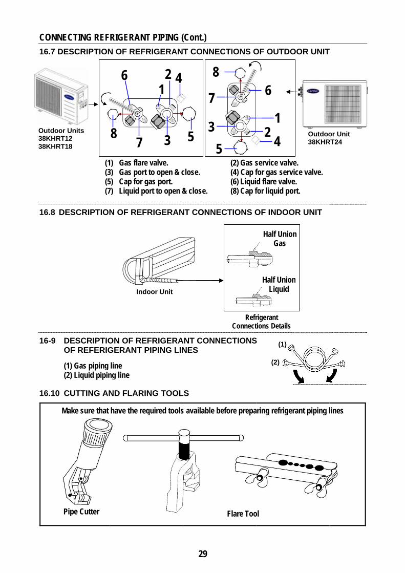
16.7 DES
16.8 DES
16-9 DE OF
(1) (2)
16.10 CU
Mak
Pip
Outdoor Un38KHRT12 38KHRT18
TING REFSCRIPTION
(1(3(5(7
SCRIPTION
ESCRIPTIOF REFERIG
Gas piping Liquid pipin
UTTING AN
ke sure that
pe Cutter
nits
RIGERANTN OF REFR
) Gas flare3) Gas port5) Cap for g7) Liquid po
N OF REF
ON OF REGERANT P
line ng line
ND FLARI
have the req
7
6
8
Ind
T PIPING (RIGERAN
e valve. to open & c
gas port. ort to open &
FRIGERAN
EFRIGERAPIPING LIN
NG TOOL
quired tools
4 2
3
1
oor Unit
29
(Cont.) T CONNE
close.
& close.
NT CONNE
ANT CONNNES
LS
s available b
5 5
3
7
8 CTIONS O
(2) Gas s (4) Cap f (6) Liqui (8) Cap f
ECTIONS O
Refr Connect
NECTIONS
before prepa
Flare Too
5
OF OUTDO
service valvfor gas servd flare valvefor liquid po
OF INDOO
rigerant tions Details
S
aring refriger
Half UnioGas
Half Union Liquid
ol
(1)
(2)
4 2 1
6
OOR UNIT
e. vice valve. e.
ort.
OR UNIT
rant piping l
n
n
Outdoo38KHR
T
lines
or Unit RT24

C1
( IN
S
••
•
S
S•
••
•
CONNECTI
6-11 STEN CASE OF
STEP (1): C
• Remove • Position
required
NOTE • Take care
90° angleillustratioand inco
STEP (2): R o w
This proccarefullygas leaki
NOTE When reabe sure t
STEP (3): F• Use flare
piping lintube and
NOTES 1) Good fla• Inside su• Edge is s
or imperf• Tapered
2) Be sureto preverefrigera
3) Avoid ior cracksurface
ING REFRIEPS OF PR NOT USING
Cutting re
protective c tube end do length with
e to ensure e with the sions for examrrectly.
Removingof refrigerwith a reacess is impo to make a ging out.
aming, hold that no copp
Flaring thee tool to flarenes and then modify the
are should hurface is glosmooth and fections. sides are of
e to apply a sent dust or wation piping
incorrect flaked or inclin.
IGERANT REPARINGG THE OPTIO
efrigerant
caps from coownwards, c a pipe cutte
that the cut de of pipe, a
mples of edg
g burrs at rant pipingamer ortant and sgood flare a
the pipe enper scraps fa
e Piping e ends of bon slide a flar flare.
have the follossy and sm must not ha
f uniform len
sealing cap water from gg lines befor
aring, which ned with une
PIPING LING REFRIGONAL FACT
piping lin
opper pipe ecut the pipe er.
edge remaiand refer to ges cut corr
the ends g lines
hould be dond to preven
nd downwardall into the p
oth gas and re nut on to
owing propeooth. ave any burr
ngth.
or waterprogetting into tre they are u
results in deven thickne
30
NES (ContERANT PORY REFRI
nes
ends. to the
ins at a the ectly
one nt any
d and pipe.
liquid the
erties :
rs
oof tape the
used.
amaged ess
1
2
12
R
t.) IPING LINGERANT PIPipe Cutter
1
: Connectio: Reamer
Recommend
Flare too
RefrigeraPiping
ES BEFOPING LINES
Befo
r
Correct Cutting
90°
on pipes
ded
ol
ant g
1/4” 3/8” 1/2”
RE CONNS WITH THE
Debarring
ore
Inclined Cutting
Flare
Ø A6.35 mm 9.52 mm 12.7 mm
Corrugated Cutting
Wrap Cutting
NECTIONS FLARE NUT
After
Nut
A (+0 ÷ –0.4) 9.1 mm 13.2 mm 16.6 mm
S TS )

COST
S
•
S
•
•
S
•
•
S
•
•
ONNECTIN
TEPS OF
STEP (4): R o i
NOTES
• Do not reindoor unfor conne
STEP (5): R o o
NOTES
• Do not reoutdoor ufor conne
• It is easiethe outdosupport.
STEP (6): M o
• Mount garefrigeran
• Mount liqside of liq
STEP (7):
• Mount gaof gas re
• Mount liqof liquid
NG REFRIGPREPARIN
Removingof gas andindoor uni
emove protenit until refrections.
Removingof gas andof outdoor
emove proteunit until refection. er to removeoor unit befo
Mounting of refrigeras flare nut (nt piping linquid flare nuquid refrige
Mountingends of r
as flare nut (frigerant pip
quid flare nurefrigerant p
GERANT PNG REFRI
g protectivd liquid coit.
ective plasticigerant pipin
g protectivd liquid cor unit.
ective plasticfrigerant pip
e protective ore being in
flare nutsrant piping( large nut )
ne. ut ( small nurant piping l
g flare nutrefrigerant(Large nut) oping line. ut (Small nutpiping line.
PIPING LINIGERANT
ve plastic onnections
c nuts from ng lines are
ve plastic onnections
c nuts from ping lines ar
plastic nutsstalled on th
s on the eng
on the end
t ) on the otline.
ts on the ot piping lion the other
t) on the oth
31
NES (Cont.PIPING L
nuts s of
the ready
nuts s
the re ready
s from he wall
nds
of gas
ther
other nes r end
her end
P
P
) INES BEF
G In
Liq In
Liquid Piping Line
Gas Piping Line
RefConnect
FORE CON
as linen indoor unit
quid line indoor unit
Liquid
Gas Li
frigerant Pipting Flare Nu
NNECTION
t
Line
ine
ping Lines Auts From Bo
NS (Cont.)
After oth Sides

CONNEC 16-12 ST
Connecrespectunions
A. Lubric
line enhalf unoil. This isleaks.
B. For pr
gas uneach othe flasmoot
C. Then hwrencthe tigBe carthread
NOTES
1.
2.
16-13 STE
• Connecpiping flare va
• Repeatrefrigeroutdoo
(Fingers tiseveral tuflare nutsfirst to obsmooth m
TING REF
TEPS OF C
cting gas atively withof indoor
cate flare nund and the tnions of ind
s effective fo
roper connenion pipe another, then fare nuts tighth match.
hold the unich and tighteghtening torreful not to dds.
Insufficientwill cause Over tightewill damagand cause
EPS OF C
cting the othlines respec
alves of the t steps (A), (rant piping l
or unit.
(1) ighten urns the s tightly at btain a match
RIGERANT
CONNECT
and liquidh gas and
unit.
uts of gas anhreads of th
door unit wit
or reducing
ction, align nd flare pipefinger tightehtly at first to
ion side withen the flare nque indicatedamage the
t tightening refrigerant lening the torge the tube f refrigerant
ONNECTI
her ends of ctively with outdoor uni
(B), (C) whenlines to the f
T PIPING (
TING REFR
d piping linliquid half
nd liquid piphe gas and lth anti – free
refrigerant
the centerse straight witen several tuo obtain a
h a double-enut by applyed in the tab flare nut
torque eaks. rque laring leaks.
NG REFR
gas and liqugas and liquit. n connectinflare valve o
32
(Cont.)
RIGERAN
nes f
ping iquid
eze
of th
urns
ended ying ble.
RIGERANT
uid uid
g of the
Tiwiwrwr
Indo
P
in131
T PIPING
T PIPING L
(2) ghten flare nith adjustabrench or torrench.
oor unit tubing
Refrigerant Piping Lines
Flare Nut nch Mm1/4” 6.353/8" 9.521/2” 12.
Indoor U
Tighte
LINES TO
LINES TO
Lubricate
nuts le
rque
g Flar
s
Tightm N.M 5 15-202 31-357 50-55
nit
ening Torqu
O INDOOR
OUTDOOR
Flare SpaTorque W
Indoor Pipin
RefrigePiping L
Pipire Nut
tening TorqKgf - c
0 150-25 310-35 500-5
e
R UNIT
R UNIT
anner or Wrench
Indoor Side
Unit ng
erant Lines
ng Line
ue cm 00 50 50

33
CONNECTING REFRIGERANT PIPING LINES (Cont.)
16-14 AIR PURGING OF INDOOR UNIT AND REFRIGERANT PIPING LINES
16-14-1 INTRODUCTION
• In some countries the law does not permit purging by blowing refrigerant through the lines. If this is the case, please refer to page (35) using the vacuum pump.
• The air in the indoor unit and in the refrigerant piping must be purged. If air remains in the refrigeration piping, it will have undesirable effects as indicated below :
Pressure in the system rises. Operating current rises. Cooling efficiency drops. Moisture in the refrigerant circuit may freeze and block capillary tubing. Water may lead to corrosion of parts in the refrigeration system.
• Be sure, using a torque wrench to tighten the service port cap ( after using the service port ), so that it prevents the gas leakage from the refrigeration cycle.
16-14-2 AIR PURGING OF INDOOR UNIT AND REFRIGERANT PIPING LINES USING REFRIGERANT CONTAINED IN OUTDOOR UNIT The outdoor unit includes an extra 50 grams of refrigerant for air purge.

34
CONNECTING REFRIGERANT PIPING LINES (Cont.)
AIR PURGING OF INDOOR UNIT AND REFRIGERANT PIPING LINES USING REFRIGERANT CONTAINED IN OUTDOOR UNIT (Cont.)
Air purging procedure: (1) Recheck the refrigerant piping connections. (2) Open the valve stem of the 2-way liquid valve counterclockwise approximately 90°,
wait 10 seconds, and then set it to closed position.
• Be sure to use a hexagonal wrench to operate the valve stem. (3) Check for gas leakage from flare connections. (4) Purge the air from the system
• Set the 2-way liquid valve to the open position and remove the cap from the 3-way gas valve’s service port.
• Using the hexagonal wrench to press the valve core pin, discharge for three seconds and then wait for one minute.
(5) Use torque wrench to tighten the service port cap to a torque of 1.8 kg.m. (18 Nm) (6) Set the 3-way gas valve to the open position. (7) Mount the valve stem nuts to the 2-way liquid and 3-way gas valves. (8) Check for gas leakage.
• At this time, especially check for gas leakage from the 2-way and 3-way stem nuts, and from the service port.
CAUTION
If gas leakage is discovered in step (3) above, take the following measures.
• If the leaks stop when the piping connections are tightened further, continue working from step (4).
• If the gas leaks do not stop when the connections are retightened, repair the location of the leak, discharge all of the gas through the service port, and then recharge with the specified amount of gas from a gas cylinder.
35
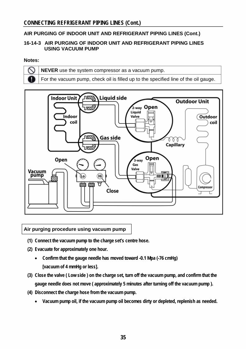
CONNECTING REFRIGERANT PIPING LINES (Cont.) AIR PURGING OF INDOOR UNIT AND REFRIGERANT PIPING LINES (Cont.) 16-14-3 AIR PURGING OF INDOOR UNIT AND REFRIGERANT PIPING LINES
USING VACUUM PUMP Notes:
NEVER use the system compressor as a vacuum pump.
For the vacuum pump, check oil is filled up to the specified line of the oil gauge.
Air purging procedure using vacuum pump
(1) Connect the vacuum pump to the charge set’s centre hose. (2) Evacuate for approximately one hour.
• Confirm that the gauge needle has moved toward -0.1 Mpa (-76 cmHg) [vacuum of 4 mmHg or less].
(3) Close the valve ( Low side ) on the charge set, turn off the vacuum pump, and confirm that the gauge needle does not move ( approximately 5 minutes after turning off the vacuum pump ).
(4) Disconnect the charge hose from the vacuum pump.
• Vacuum pump oil, if the vacuum pump oil becomes dirty or depleted, replenish as needed.

36
CONNECTING REFRIGERANT PIPING LINES (Cont.)
16-15 PUMPING DOWN (RE-INSTALLATION) • INTRODUCTION
Pump down means collecting all the refrigerant in the system back into the outdoor unit. Pump down must be actuated before disconnection of pipes, to avoid loss of refrigerant gas. Pump down is used when the unit is moved to another installation location or when the system is repaired.
Pumping down Procedure (1) Confirm that both the 2-way liquid and 3-way gas valves are set to the open position.
• Remove the valve stem caps and confirm that the valve stems are in the open position. • Be sure to use a hexagonal wrench to operate the valve stems.
(2) Operate the system for 10 to 15 minutes. (3) Stop operation and wait for 3 minutes, then connect the charge set to the service port of the 3-way
gas valve. • Connect the charge hose with the push pin to the gas service port.
(4) Air purging of the charge hose. • Open the low-pressure valve on the charge set slightly to purge air from the charge hose.
(5) Set the 2-way liquid valve to the close position. (6) Operate the air conditioner at the cooling cycle and stop it when the gauge indicates 0.1MPa. (7) Immediately set the 3-way gas valve to the closed position.
• Do this quickly so that the gauge ends up indicating 0.3 to 0.5Mpa. (8) Disconnect the charge set, and mount the 2-way liquid and 3-way gas valve’s stem nuts and service port caps.
• Use a torque wrench to tighten the service port cap to a torque of 1.8 kg.m (18 N.m) Be sure to check for gas leakage.

37
CONNECTING REFRIGERANT PIPING LINES (Cont.) 16-16 REFRIGERANT LEAK CHECK
After connecting the refrigerant piping lines with both outdoor and indoor units check the joints for refrigerant leakage by using one of the following methods : (1) Soapy water method
Apply a soapy water or a liquid detergent on the indoor unit connections or outdoor unit connections by a soft brush to check for leakage of the connecting points of the piping. If bubbles come out, the pipes have leakage and must be repaired.
(2) Refrigerant leak detector method
Use the leak detector to check for leakage.
16-17 INSULATING REFRIGERANT PIPING LINES
To conserve energy and prevent wet floors due to condensation, the gas and liquid piping lines must be well insulated with a proper insulation material.
The thickness of the insulation should be a minimum of 9 mm.
The insulation you select must have good insulation characteristic, be easy to use, resist age and not easily absorb moisture.
Finally wrap the flare couplings and pipes with insulation and tighten this with tape without exerting too much pressure on the insulation.
CAUTION
• After a pipe has been insulated, never try to bend it into a narrow curve, as this way will cause the pipe to break or crack.
• Repair and cover any possible cracks in the insulation • Avoid dripping due to insufficient insulation of piping.
Pipe Insulation
Pipe
Fastening tape

38
17. CONNECTING CONDENSATE DRAIN LINE
17-1 SIZE OF CONDENSATE DRAIN LINE The condensate drain line (not supplied) for indoor unit must be made of PVC piping with an inside diameter of 5/8” (16 mm) and have suitable length for the chosen installation site.
17-2 POSSIBLE OUTLET LOCATIONS OF CONDENSATE DRAIN LINE WITH REFRIGERANT PIPING LINES AND ELECTRICAL CABLES FROM THE INDOOR UNIT
NOTES
1. For the left-hand and right-hand piping, remove the pipe cover from the side panel.
2. Explain to the clients that the pipe
cover must be kept as it may be used when relocate the air conditioner to any other place
Back right condensate drain line
Back left condensate drain line
Right side condensate drain line
Left side condensate drain line
1
2
3
4

(1)
(2)
(3)
(4)
AvAv
AvAv
CONNEC
17-3 INST
The drain hgradually i to the outsof condens
Avoid puttihose end in
Avoid upwathe drain hoover-flowingwater.
Avoid kinkavoid hampdue to air st
void horizontvoid horizont
void vertical kvoid any rise
CTING COTRUCTION
hose must bnclined dowside to ensusate water to
ng the drainnto water.
ards loops inose to avoidg of conden
ks or bends ipering smootagnation.
al kinks or beal drain line w
kinks or bend in drain line
ONDENSATNS OF CO
be wnwards ure flow o outside.
n
n
nsate
in the drain oth drainage
ends with less than
ds
TE DRAINONNECTIN
hose to of water
n 2 % slope
39
N LINE (CoNG CONDE
(5) Avo
(6) Avoi
(7) Avoidsystemust head evacu
(8) DrainCheck thinto the the drain
ont.) ENSATE D
id forming a
d forming a
d connectingem drain wit be calculate in order to auation.
nage Test he drainage unit drain pa
n hose and t
DRAIN LIN
a trap in the
double trap
g condensahout approped accordinallow suffic
of the unit ban and ensuthere is no le
Trap
Trap
Ha
Refrigerant
NE
drain hose
p in the drain
te piping to priate trap. Tng to the uniient and con
by pouring sure it flows feakage from
p
water leaka
Never from
as the same ef
pipe Drain
n hose
sewage Trap height t discharge
ntinuous wa
some water freely throug
m other parts
age will cause
double -trap
ffect as a trap
n pipe
ater
gh s.

40
18. CONNECTING ELECTRICAL WIRING 18-1 ELECTRICAL WIRING BETWEEN ELECTRICAL POWER SUPPLY
AND CIRCUIT BREAKER OF AIR CONDITIONER All electrical connections between electrical power supply and circuit breaker of air conditioner are the responsibility of the customer and must be done by a qualified electrical technician according to national electrical wiring regulations to avoid fire due to short-circuiting.
(A) Operating Voltage The operating voltage of electrical power supply should be within the limits of voltage mentioned
on unit nameplate data. (B) Electrical kWh Counter KWH The capacity of electrical kWh counter should be lager than the operating currents required for air
conditioner(s) and any other electrical domestic appliances in use simultaneously from the same supply.
(C) Electrical Distribution Box The installation of electrical distribution box after the electrical KWH counter is necessary
to properly distribute the electrical loads. The electrical distribution box should be equipped with circuit breakers according to the electrical
loads. For each installed air conditioner, a separate circuit breaker with its own overload should be
installed on the electrical distribution box. (D) Operation On / Off Circuit Breaker The installation of two pole automatic circuit breaker is necessary to operate the air conditioner.
The circuit breaker must be installed to be far away from any flammable materials (curtains…etc.). The circuit breaker must be suitable for air conditioner as the table “ ELECTRICAL DATA “ Page (42) Do not use operation ON / OFF circuit breakers except the approved models for use with air
conditioners. (E) Electrical Cable Do not use electrical connection cables except the approved for use with air conditioners. The power cable should be a complete unit, without extensions. The power cable size must be suitable for the air conditioner with length up to 10 meter.
See table “ ELECTRICAL DATA “ page (42).
(F) Electrical Wiring a. Make ground connection prior to any other electrical connections in accordance with the
electrical codes.
b. Ensure that mains supply connection is made through a switch that disconnects all poles, with contact gap of at least 3 mm.
c. Avoid slack connections of the electrical cords when connected to the terminal blocks of indoor
and outdoor units. These slack connections lead to voltage drop and unit malfunctions.
WARNING
!

41
CONNECTING ELECTRICAL WIRING (Cont.)
18-2 ELECTRICAL WIRING BETWEEN INDOOR UNIT, OUTDOOR UNIT AND CIRCUIT BREAKER OF AIR CONDITIONER
All electrical works including selection, installation of circuit breaker of air conditioner and all electrical connections between the outdoor unit, indoor unit and circuit breaker are the responsibility of the qualified installer and must be done according to national electrical wiring regulations to avoid fire due to short circuiting.
- Both of the outdoor and indoor units leave the factory with complete internal electrical wiring. Do not change any internal electrical wiring of both units. - It is very important before making the electrical connections between the indoor, outdoor units,
and the power supply, to pay attention to the following safety instructions:
(A) Operating Voltage The operating voltage of electrical power supply should be within the limits of voltage mentioned on
unit nameplate data shown on the indoor and outdoor units of the air conditioner.
(B) Field Electrical Connection Cables * Do not use electrical connection cables except the approved one for use with air conditioners. * Each cable should be a complete unit, without extensions. * Do not use extension cables, If extension cables are needed, use terminal block.
(C) Electrical Connections a. Electrical connections must be performed in compliance with national and local wiring codes and
standards.
b. Check that the electrical connections between the terminal blocks of indoor and outdoor units are in accordance with the wiring diagrams and caution field electrical wiring contained in the manual.
Miswiring may cause malfunction of the system and an electric shock. c. Do not connect wires when power is ON. d. Make ground connection prior to any other electrical connections in accordance with the electrical
local codes.
e. Make electrical connections between outdoor and indoor units prior to proceeding to mains supply connection.
f. Before proceeding with the unit connection to the mains supply locates live L and neutral N, then make connections as shown in the wiring diagram.
Be sure that the live and neutral wire connected respectively to the Live (L) and the Neutral (N) terminals of terminal block of outdoor units.
g. Ensure that mains supply connection is made through a switch that disconnects all poles, with contact gap of at least 3 mm.
h. Avoid slack connections of the electrical cables when connected to the terminal blocks of indoor and outdoor units. and also to circuit breaker These slack connections lead to voltage drop and unit malfunctions. Every wire must be connected firmly.
WARNING
!

42
CONNECTING ELECTRICAL WIRING (Cont.) 18-3 ELECTRICAL DATA
Split System Model
Starting Current (Note 1)
Nominal System Power Supply
Electrical Consumption Circuit
Breaker 35 °C *
46 °C **
52 °C ***
Cool Only Amp V/1Ph/50Hz Amp Watt Amp Watt Amp Watt Amp
53KHRT12 35 220-240 5.8 1250 7.2 1475 8.1 1803 16
53KHRT18 52 220-240 8.9 1889 10.4 2255 11.2 2461 20
53KHRT24 82 220-240 11.7 2355 12.6 2827 14.2 3075 25
NOTES
1. Starting Current duration is usually less than 1 Second.
2. Operating Conditions. * @ 35ºC db outdoor temperature :
27/19ºC db/wb Indoor Temperature. High air flow of indoor unit motor ** @ 46ºC db outdoor temperature :
29/19ºC db/wb Indoor Temperature. High air flow of indoor unit motor *** @ 52ºC db outdoor temperature :
32/23ºC db/wb Indoor Temperature. High air flow of indoor unit motor

43
CONNECTING ELECTRICAL WIRING (Cont.)
18-4 FILED CONNECTIONS ELECTRICAL WIRING
systems 53KHRT12 & 53KHRT18 system 53KHRT24
LEGEND Earth 1 Live power supply. 2 Neutral power supply.
LEGEND Earth L Live power supply. N Neutral power supply. 1 Live connection indoor unit / outdoor unit. 2 Neutral connection indoor unit / outdoor unit S Communication connection indoor unit / outdoor units
Sizes of electrical wires Model L N 1 2
53KHRT12 3 mm2
3 mm2
3 mm2
3 mm2
53KHRT18 4 mm2
4 mm2
4 mm2
4 mm2
Sizes of electrical wires Model L N 1 2 S
53KHRT24 4 mm2
4 mm2
1 mm2
1 mm2
1 mm2
NOTES (1) Connect the power supply to the
indoor unit and then get the power required for the outdoor unit from the indoor unit.
(2) All dotted lines to be fitted by installer. (3) Refer to wiring diagrams and
stickers-caution sticked inside the outdoor & indoor units.
NOTES (1) Connect the power supply to the outdoor unit and then
get the power required for the indoor unit from the outdoor unit.
(2) All dotted lines to be fitted by installer. (3) Refer to wiring diagrams and stickers-caution sticked inside the outdoor & indoor units.
Live Neutral
220-
240V
~ 50
Hz 1
Ph
Circuit Breaker
Main Switch
Indoor Unit
Earth
Outdoor Unit
220-
240V
~ 50
Hz 1
Ph
Circuit Breaker Main Switch
Outdoor Unit
Indoor Unit

44
Piping
Decorative TapeSaddles
19. FINISHING INSTALLATION
FINISHING STEPS FOR INSTALLATION
a. Tie together refrigerant piping, drain hose, electrical connection cords. Form the refrigerant piping in the required direction and bind the drain hose, electrical connection cord and signal line together with vinyl tape. • The drain hose should be always at the bottom
of lump to assure smooth drainage. • The lump must be of circular shape. • Fix piping with pipe clamps and check that any
pipe vibrations cannot be transmitted to the building structure.
d . Ensure that the remote control and control functions are working properly
b. Fill the gap between the outside wall pipe hole and the piping with sealing wall sleeve, wall cap and sealer so that rain and wind cannot enter.
e . Adjust the vertical louvers of supply air for correct air diffusion to the right or left direction as per the requirements for the room to be air-conditioned
c. After completion of electrical wiring to the indoor unit : Install the window cover of the terminal block and fixit by using the fixing screw.
f. Ensure that the air distribution in the room is uniform by properly adjusting the air flow direction.
g. After completion of electrical wiring to the outdoor unit:
• Fasten the electrical cords with the cable clamp. • Install again the service door.
Wall Sleeve Wall Cap
Sealer Putty
Outdoor side Wall
Indoor Side
Liquid Line
Drain Hose
Suction Line
Panel
Window cover
Vertical Louver
45
20. TEST RUNNING
20.1 PRECAUTIONS BEFORE TEST RUNNING
- Operate test running after checking that the air filters and front panel are properly mounted. - Operate testing running after completion of connecting refrigerant piping lines,
drain line and electrical wiring
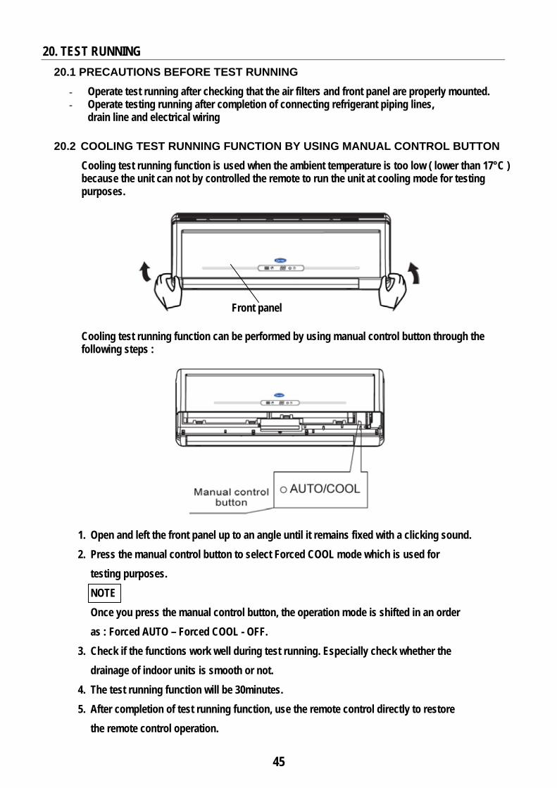
20.2 COOLING TEST RUNNING FUNCTION BY USING MANUAL CONTROL BUTTON Cooling test running function is used when the ambient temperature is too low ( lower than 17°C ) because the unit can not by controlled the remote to run the unit at cooling mode for testing purposes.
Cooling test running function can be performed by using manual control button through the following steps :
1. Open and left the front panel up to an angle until it remains fixed with a clicking sound. 2. Press the manual control button to select Forced COOL mode which is used for
testing purposes. NOTE Once you press the manual control button, the operation mode is shifted in an order as : Forced AUTO – Forced COOL - OFF.
3. Check if the functions work well during test running. Especially check whether the drainage of indoor units is smooth or not.
4. The test running function will be 30minutes. 5. After completion of test running function, use the remote control directly to restore
the remote control operation.
Front panel

46
TEST RUNNING (Cont.) 20.3 STEPS OF COOLING TEST RUNNING for model 53KHRT12
(1) Move circuit breaker to ON position. (2) Operate the system for cooling at high fan speed by using wireless remote control (3) After system operation becomes stabilized: - Measure low pressure to check correct
refrigerant charge. (See figure & table) - Measure total Amps consumed by the system.
System Cooling Test Running
SYSTEM MODEL 53KHRT12 53KHRT18 AMBIENT TEMP ºC 35 46 52 35 46 52 LOW PRESSURE PSI 70 74 76 60 62 63 TOTAL AMPS 5.6 7.2 8.1 8.9 10.4 11.2
Note: Readings at 220 volt and 27 ºC return air to indoor unit and high speed of indoor unit motor.
20.3 STEPS OF COOLING TEST RUNNING for models 53KHRT18 & 53KHRT24
(1) Move circuit breaker to ON position. (2) Operate the system for cooling at high fan speed by using wireless remote control (3) After system operation becomes stabilized: - Measure low pressure to check correct
refrigerant charge. (See figure & table) - Measure total Amps consumed by the system.
System Cooling Test Running
SYSTEM MODEL 53KHRT24 AMBIENT TEMP ºC 35 46 52 LOW PRESSURE PSI 69 72 73.5 TOTAL AMPS 11.7 13.3 14.2
Note: Readings at 220 volt and 27 ºC return air to indoor unit and high speed of indoor unit motor.
Outdoor Unit
Details (1)
(1) Low Pressure Measuring.
(1) Low Pressure Measuring.
(1)
Outdoor Unit Details
47
21. AIR CIRCULATION FOR INDOOR UNIT
AIR FLOW DIRECTION CONTROL Air is supplied into the room through the supply air louvers located on the bottom of the indoor unit. Air from the room is drawn into the indoor unit through the front panel and filters which are located
behind the front panel.
Make absolutely sure that the supply and return air flow of the indoor unit are not obstructed (even partially).
• Adjust supply air direction properly otherwise, it might
cause discomfort or cause uneven room temperatures.
• Adjust the horizontal louver using the remote control.
• Adjust the vertical louvers manually.
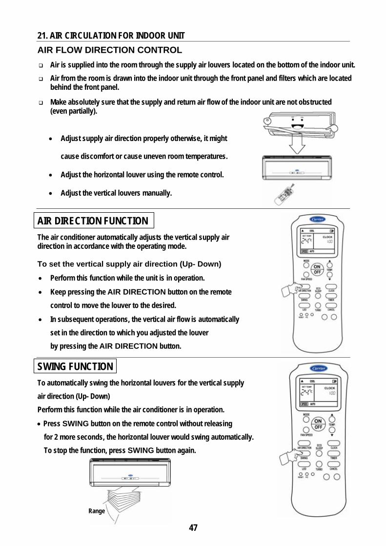
AIR DIRECTION FUNCTION The air conditioner automatically adjusts the vertical supply air direction in accordance with the operating mode. To set the vertical supply air direction (Up- Down)
• Perform this function while the unit is in operation.
• Keep pressing the AIR DIRECTION button on the remote control to move the louver to the desired.
• In subsequent operations, the vertical air flow is automatically set in the direction to which you adjusted the louver by pressing the AIR DIRECTION button.
SWING FUNCTION To automatically swing the horizontal louvers for the vertical supply air direction (Up- Down) Perform this function while the air conditioner is in operation.
• Press SWING button on the remote control without releasing for 2 more seconds, the horizontal louver would swing automatically. To stop the function, press SWING button again.
Range

48
AIR CIRCULATION FOR INDOOR UNIT (Cont.)
CAUTION
• The AIR DIRECTION and SWING buttons will be disabled when the air conditioner is not in operation ( including when the TIMER ON is set ).
• Do not operate the air conditioner for long periods with the supply air direction set downward in cooling or dry mode. Otherwise, condensation may occur on the surface of the horizontal louver causing moisture to drop on to the floor or on furnishings.
• Do not move the horizontal louver manually. Always use the AIR DIRECTION or SWING button. If you move horizontal louver manually, it may malfunction during operation. If the louver malfunctions, stop the air conditioner once and restart it.
• When the air conditioner is started immediately after it was stopped, the horizontal louver might not move for approximately 10 seconds.
• Open angle of the horizontal louver should not be set too small, as cooling performance may be impaired due to too restricted air flow area.
• Do not operate unit with horizontal louver in closed position.
• When the air conditioner is connected to power (initial power), the horizontal louver may generate a sound for 10 seconds, this is a normal operation.
To set the horizontal supply air direction (left - right)
Adjust the vertical louvers manually using the lever on the vertical louver arm. Take care not to catch fingers on the fan, horizontal louver or to damage vertical louvers. When the air conditioner is in operation and the horizontal louver is in a specific position, move the lever of vertical louvers to right or left to adjust horizontal supply air.
Range
Vertical Louver

49
22. AFTER INSTALLATION CHECK LIST
22.1 INDOOR UNIT
a. The installation location is adequate.
b. The unit is solidly mounted and leveled.
c. The air filters are installed correctly.
d. The vertical deflectors of supply air are manually adjusted for correct air diffusion.
22.2 OUTDOOR UNIT
a. The installation location is adequate.
b. The unit is solidly mounted and leveled.
c. The wall support is fixed properly with the wall.
d. The service door and its fixing screw are replaced.
22.3 REFRIGERANT PIPING LINES CONNECTIONS
a. The refrigerant piping lines are adequate with system model.
b. The insulation is wrapped on the coupling connections.
c. The air purge is properly done.
d. The refrigerant piping lines are tested for refrigerant leakage.
e. The gas and liquid service valves in outdoor unit are open.
f. The cap nuts for flare valves are properly tightened.
22.4 CONDENSATE DRAIN LINE CONNECTIONS a. The Condensate drain line from indoor unit is gradually inclined downwards to the
outside.
b. The Condensate water flow smoothly.
22.5 ELECTRICAL CONNECTIONS a. The operating voltage electrical power supply is in the voltage range shown on the
unit’s nameplates.
b. The sizes of electrical connection cords are adequate according to system model.
c. The size and type of unit circuit breaker are adequate according to system model. d. The electrical wiring connections between power supply, outdoor unit, indoor unit
and circuit breaker are adequate.
e. All fields electrical wiring connections are tightened and secured.
f. The earth wire is connected to the ground.

50
AFTER INSTALLATION CHECK LIST (Cont.)
22.6 FINISHING INSTALLATION a. The refrigerant piping lines, electrical cables and drain hose are lumped together.
The drain hose is at the bottom of lump.
b. The wall passage hole is properly sealed.
22.7 TESTING RUNNING a. The cooling cycles are tested
At least one complete cooling cycle of unit operation is observed.
b. There is no any abnormal noise or vibration from the outdoor unit during operation.
c. There is no any abnormal noise or vibration from the indoor unit during operation.
d. The wireless remote control operate Correctly.
e. Each lamp on the indoor unit lights normally.
22.8 CUSTOMER GUIDANCE a. The correct operation of the air conditioner has been explained to the customer
including the following points:
• Starting and stopping of air conditioner
• Operation mode adjustment
• Temperature adjustment
• Fan speed adjustment
• Horizontal supply air flap adjustment
• Vertical supply air flap adjustment
• Other remote control functions
• Filter removal and cleaning
b. The owner’s and installation manuals have been given to the customer.

23. SELF
EXPLAINA
- Self-diag- The prin
to detec - Once a m
MaR
Return Air ( open or sIndoor Coi( open or sIndoor Fanout of cont1 minute Compressocuts out 4 Electronic ( EEPROM
No over – z
Refrigeran
Leds Statu
X = OFF = ON = Flas = Flas
1- Priorbreak
2- After 2-1 c 2-2 o
F DIAGNOSATION OFgnostic func
nted circuit bct malfunctiomalfunction
Hi Wall S53KHR53KHR
lfunction Reason
Sensor short circuit l Sensor
short circuit n Motor has trol for over
or Overload times Control PCB error )
zero signal
nt leak
us Refers
F
sh at 5Hz sh continuo
r to the malfuker to OFF pr repairing thconnect the operate the a
STIC FUNCF SELF-DIAction is the boards existon and autom is detected
plit SystemRT12-708 RT18-708
L
)
) been
d XB
To Malfun
ously
unction repaposition. he malfunctelectrical mair condition
Indoor U
CTION FORAGNOSTICkey for succting inside tmatically sto
d, the lamps
ms
Led
Le
X
X
ction Reas
air, disconn
tion: main supply bner by using
nit
51
R MALFUNC FUNCTIOcess of air cthe indoor uops the ope of the indoo
ed
Ret
( op
Ind
( op
X Out( op
Com
cut
Ele
( EE
Ind
Com
Out
wor Ref
son Le
X
NOTES ect the elec
by moving tg the wireles
NCTIONS DON conditioner onit are equipration at theor unit be as
H
MalfunctReaso
turn Air Senpen or shortoor Coil Senpen or short
tdoor Coil Spen or short
mpressor Ots out 4 timectronic ConEPROM defeoor / Outdoommunicatiotdoor unit prks frigerant lea
ds Status
X = OFF = ON = Flash = Flash
trical mains
he circuit brss remote co
DETECTIO
operation. pped with see air conditios per the bel
Hi Wall Sp53KHR
tion n
nsor t circuit ) nsor t circuit )
Sensor t circuit )
verload es ntrol PCB ect ) or units n error rotection
ak
Refers To
h at 5Hz h continuou
s supply by m
reaker to ONontrol.
N
elf-diagnostoner. low tables :
plit SystemRT24-708
Led
X
X
X
X
Malfuncti
usly
moving the
N position
Display Pa
tic function
ms
Led
X
X
X
X
on Reason
circuit
nel
Led
X
X
X
X
X
X
n

www.miraco.com.eg


![[Castagna J.P.] AVO Course Notes, Part 3. Poor AVO](https://img.pdfslide.net/doc/110x75/563db964550346aa9a9ce6c7/castagna-jp-avo-course-notes-part-3-poor-avo.jpg)