Embed Size (px)
Citation preview

Hiding Signatures in Graph ColoringSolutions
Gang Qu and Miodrag PotkonjakComputer Science Department, University of California, Los Angeles, CA 90095, USA
fgangqu,[email protected]
Abstract. One way to protect a digital product is to embed an au-thor's signature into the object in the form of minute errors. However,this technique cannot be directly applied to protect intellectual proper-ties such as solutions to hard problems which must maintain the cor-rect functionality. This paper proposes a constraint-based watermarking
technique and lays out a theoretical framework to evaluate this type oftechnique. Based on this framework, we analyze three watermarkingtechniques for the graph coloring problem because of its theoretical im-portance in complexity theory and numerous applications in real life.The �rst adds extra edges between some pairs of vertices and thereforeforces them to be colored by di�erent colors. The second pre-colors a setof well-selected vertices according to the watermark. And the last intro-duces new vertices and edges to the graph. Since credibility and overheadare the most important criteria for any e�cient watermarking technique,we derive formulae which explicitly illustrate the trade-o� between highcredibility and low overhead. Asymptotically we prove that for almostall random graphs Gn;p, an arbitrarily high credibility can be achievedby all proposed watermarking techniques with at most 1-color-overhead.Numerical simulation on random graphs shows that a large amount of in-formation can be embedded with very low overhead. We also watermarkseveral sets of graphs generated from real-life benchmarks. Almost allthe watermarked graphs, with a huge watermark embedded, can be col-ored with the known minimal number of colors for the original instanceswith no run-time overhead.
1 Introduction
Suppose that you have developed a very e�cient heuristic to solve a well-knownhard problem, for example the graph (vertex) coloring (GC) problem. You testyour program on real-life benchmarks and your solutions outperform the bestknown solutions, then you decide to put your solutions online on a pay-per-usebase to recoup the cost of developing your software. Since the solutions you postare heavily used in real-life and soon you will �nd yourself a target of pirates,who purchase your solutions and then resale them at a lower price. Even if youcatch the dishonest buyer, he/she can claim that he/she solves the problem byhimself/herself. To protect your intellectual property (IP), you need to prove toa third-party that your are the creator and owner of this solution.
In this paper, we propose a constraint-based watermarking technique for in-
1

tellectual property protection (IPP). Instead of solving the real problem andposting the answer directly, we build a watermarking engineer which takes thereal problem and the owner's signature as input and gives a solution to the initialproblem. Inside the watermarking engineer, we translate the signature into aset of additional constraints and add them into the original problem. Therefore,the solution will satisfy both the original and additional constraints. I.e., in thissolution, there exist special structures that cannot be easily discovered withoutthe owner's signature. Now the owner can claim his/her authorship by showingthe small probability that such structures exist in a random solution withoutthe signature. Since the signature is embedded as extra constraints, there mightbe some degradation in the quality of the IP. The trade-o� between credibility(measures for the strength of proof for authorship) and overhead (measures forthe degradation of quality of the IP) has to be balanced, based on which webuild a framework to evaluate watermarking techniques. As an attempt to the-oretically analyze watermarking techniques, the primary objective of this paperis to lay out analytical foundations for all watermarking techniques, not onlythose which we discuss here.
We take the GC problem as an example to illustrate our approach becauseof its theoretical importance in complexity theory and numerous applications inreal life. The GC problem is to color the vertices of a graph with the fewestnumber of colors such that no vertices connected by an edge receive the samecolor. A watermarked solution is a coloring scheme from which the embeddedinformation can be retrieved. We propose three watermarking techniques toembed signatures into solutions of the GC problem. For each technique, weexplain how signatures can be put into the graph as extra constraints, then we dothe asymptotic analysis to answer the questions about credibility and overhead(number of extra colors required in the GC problem). Surprisingly, the resultshows that an arbitrarily high credibility can be achieved with at most one coloroverhead by all proposed watermarking techniques. This is tested by numericalsimulation on random graphs. Finally we color several sets of random graphs,graphs from real-life benchmarks and the DIMACS challenge graph. For mostinstances, the watermarked graphs can be colored with no overhead with thesame amount of run-time.
The rest of the paper is organized as follows. In section 2, we survey therelated work on watermarking, random graphs and outline the constraint-basedwatermarking IPP techniques. The framework for evaluating watermarking tech-niques is then illustrated by analyzing the three watermarking techniques for thegraph coloring problem. We report the numerical simulation and experimentalresults in section 6 and summarize our work in section 7. The proof and pseudo-code are listed in the Appendices.
2 Preliminary
Data watermarking, also known as data hiding, embeds data into digital mediafor the purpose of identi�cation, annotation, and copyright. Recently, the pro-
2

liferation of digitized media and the Internet revolution are creating a pressingneed for copyright enforcement schemes to protect copyright ownership. Severaltechniques for data hiding in digital images, audios, videos, texts and multimediadata have been developed [1, 3, 4, 5, 9, 10, 11]. All these techniques take advan-tage of the limitation of human visual and auditory systems, and simply embedthe signature to the digital data by introducing minute errors. The transparencyof the signature relies on human's insensitiveness to these subtle changes.
Watermarking for the purpose of IPP, on the other hand, is more di�cult be-cause it has to maintain the correct functionality of the initial IP. A conceptuallynew method [6], constraint-based watermarking, translates the to-be-embeddedsignature into a set of additional constraints during the design and implemen-tation of IP in order to uniquely encode the signature into the IP. The proof ofauthorship is shown by arguing the small probability for a random solution tosatisfy all these extra constraints. The e�ectiveness of this generic scheme hasbeen demonstrated at all stages of the design process [6].
A generic watermarking procedure consists of the following components:
� An optimization problem with known di�cult complexity. By di�cult, wemean that either achieving an acceptable solution, of enumerating enoughacceptable solutions, is prohibitively costly. The solution space of theoptimization problem should be large enough to accommodate a digitalwatermark.
� A well-de�ned interpretation of the solutions of the optimization problemas intellectual property.
� Existing algorithms and/or o�-the-shelf software that solve the optimiza-tion problem. Typically, the \black box" software model is appropriate,and is moreover compatible with de�ning the watermarking procedure bycomposition with pre- and postprocessing stages.
� Protection requirements that are largely similar to well-understood protec-tion requirements for currency watermarking.
A non-intrusive watermarking procedure then applies to any given instanceof the optimization problem, and can be attached to any speci�c algorithmssolving it. Such a procedure can be described as:
� A use model or protocols for the watermarking procedure. In general, eachwatermarking scheme must be aware of attacks based on design symme-tries, renaming, reordering, small perturbations (which may set require-ments for the structure of the solution space), etc.
� Algorithmic descriptions of the pre- and post-processing steps of the wa-termarking procedure. Pre- and post processing preserve the algorithmsand/or software as a \black box".
� Strength and feasibility analyses showing that the procedure satis�es givenprotection requirements on a given instance. Strength analysis requiresmetrics, and structural understanding of the solution space (e.g., \barri-ers" (with respect to local search) between acceptable solutions). Feasibil-ity analysis requires measures of solution quality, whether a watermarkedsolution remains well-formed, etc.
3

� General robustness analyses, including discussion of susceptibility to typ-ical attacks, discussion of possible new attacks, performance guarantees(including complexity analysis) and implementation feasibility.
In addition to maintaining the correct functionality of the IP, an e�ectivewatermark must satisfy the following properties:
� high credibility: The watermark should be readily detectable for the proofof the authorship. The probability of coincidence should be low.
� low overhead: The degradation of the software or design by embedding thewatermark should be minimized.
� resilience: The watermark should be di�cult or impossible to remove with-out the complete knowledge of the software or design.
� transparency: The addition of the watermark to software and designsshould be transparent so that it can be used for existing design tools.
� perceptual invisibility: The watermark must be very di�cult to detect.This is related to but not the same as the resilience problem.
� part protection: Ideally, a good watermark should be distributed all overthe software or design in order to protect all parts of it.
The theory of random graphs was founded by Erd�os and R�enyi after Erd�oshad discovered, in the middle of this century, that probabilistic methods wereoften useful in tackling extremal problems in graph theory. The traditional wayof estimating the proportion of graphs having a certain property is to obtainexact but complicated formulae. The new probabilistic approach is to approxi-mate a variety of exact values by appropriate probability distributions and usingprobabilistic ideas.
Random graphs play a very important role in many �elds of computer science.The two most frequently occurring models of random graphs are G(n;M) andG(n; p). The �rst consists of all graphs with n vertices and M edges, the secondconsists of all graphs with n vertices and the edges are chosen independentlywith probability p(0 < p < 1). We will focus on the second model and usethese conventional notations: Gn;p for an element of G(n; p), q = 1 � p; b = 1
q,
�(Gn;p) is the independent number of graph Gn;p (i.e., the maximal cardinalityof independent sets.), and �(Gn;p) denotes the chromatic number of Gn;p (i.e.,the minimum number of colors required to color the graph.). For almost allgraphs Gn;p, we have [2]:
(1) �(Gn;p) = (2 + o(1)) logb n
(2) �(Gn;p) = ( 12 + o(1)) nlogb n
The graph (vertex) coloring problem is to label the vertices of a graph withminimal number of colors such that vertices connected by an edge do not receivethe same color. This problem is NP-complete and has a lot of applications invarious �elds1. Many heuristics have been developed dedicated to it[12]. In thenext three sections, we propose techniques for watermarking the solutions tothe GC problem, and lay out the theoretical framework for technique evaluationthrough the analyses of these techniques.
1For example, Toft stated 75 interesting and easily-formulated graph coloring problems[8].
4

3 Watermarking Technique #1|Adding Edges
3.1 Generic Watermarking Procedure for the Graph Col-
oring Problem
The essence of constraint-based watermarking techniques is to add extra designconstraints in order to get a rather unique solution. This is shown explicitly inFigure 1 for the GC problem.
Suppose we have a graph Gwhich is k-colorable, the innerand outer regions in Figure 1 rep-resent the solution spaces of k-color and (k+1)-color solutionsto G respectively. We assumethat when a k-color solution isrequired, every solution in the in-ner region has equal probabilitybeing picked. The shaded area isthe solution space for the water-marked graph G0, where we im-pose our signature as additionalconstraints. Since graph G0 in-herits all the constraints of graph
�������������������������������������������������������������������������������������������������������������������������������������������������������������������������������������������������������������������������������������������������������������������������������������������������������������������������������������������������������������������������������������������������������������������
�������������������������������������������������������������������������������������������������������������������������������������������������������������������������������������������������������������������������������������������������������������������������������������������������������������������������������������������������������������������������������������������������������������������
(k+1)-color solution schemes.
Solution space for the original graph G.
k-color solution schemes.
Solution space for the watermarked graph G’.
S
A solution to theoriginal graph G.
Figure 1: Additional constraints cut thesolution space.
G, a solution to G0 is also valid for G. However, the solutions to G may violatethe new constraints in G0. By coloring graph G0 instead of G, we can obtainsolutions to G and more important, we force the solutions fall into the shadedarea. Denote nk and n0k the numbers of k-color solutions for graphs G andG0. The chance to get a particular solution S from the constraints in G is 1
nk,
which increases to 1n0k
if from the more-constrained graph G0. When nk is large
and n0k << nk, the di�erence between1nk
and 1n0k
is signi�cant and becomes a
credible evidence for the authorship.
High credibility depends not only on the amount of constraints, but alsothe \quality" of the constraints. For example, one constraint that cuts thesolution space by half is de�nitely better than 20 constraints each cutting thesolution space by less than 1%. Constraints for the GC problem are the edges:vertices connected by an edge have to receive di�erent colors. One type ofstraightforward watermarks is extra edges. By translating signature as extraedges, we make the original graph more constrained, and some solutions to theoriginal graph will become invalid for the watermarked graph. The solution spaceeventually shrinks. There are other interpretations of signatures as constraints.However, to have a transparent watermark, we require that the watermarkedgraph preserve the characteristics (e.g. connectivity, randomness, acyclicity.) ofthe original graph. In the following sections, we propose three watermarkingtechniques for the GC problems of random graphs, and investigate the impactof the corresponding watermarks to the solution space.
5

3.2 Technique Statement
Signature embedding:
Given a graph G(V;E) and a message M to be embedded in G. Let V =(v0; v1; � � � ; vn�1) and we encrypt the message into a binary stringM = m0m1 � � �(by stream ciphers, block ciphers, or cryptographic hash functions). Figure 2shows how M is embedded into the graph G as additional constraints.
Input: a graph G(V;E),a message M = m0m1 : : :
Output: new graph with message M embeddedAlgorithm:
copy G(V;E) to G0(V;E0);foreach bit mi
f �nd the nearest two vertices vi1 , vi2 thatare not connected to vertex vi;if mi = 0 add edge (vi; vi1 ) to E
0
else add edge (vi; vi2 ) to E0
greport graph G0(V;E0);
Figure 2: Pseudo code for technique # 1.
�������������������������
�������������������������
����������������������������
����������������������������
����������������������������
����������������������������
��������������������������������
��������������������������������
��������������������
��������������������
0 1 2
3 4 5
6 7 8
9 10
1 1 1
1 10
0 1
1
1
0
Figure 3: An example.
By the nearest two vertices vi1 and vi2 which are not connected to vertexvi, we mean that i2 > i1 > i (mod n), the edges (vi; vi1); (vi; vi2) =2 E and(vi; vj) 2 E for all i < j < i1; i1 < j < i2 (mod n). For example, in Figure 3,vertices 2 and 3 are the nearest two vertices that are not connected to vertex 0.The essence of this technique is to add an extra edge between two vertices, thesetwo vertices have to be colored by di�erent colors which may not be necessaryin the original graph G. Figure 3 shows a graph of 11 nodes with solid lines fororiginal edges. The message 199810 = 111110011102 has been embedded by 11dotted edges, each represents one bit marked on the edge. A 4-color scheme,ffv0; v2; v6g; fv1; v7; v10g; fv3; v8; v9g; fv4; v5gg, is shown as well.
Signature recovering:
How can we read the watermark from the solution? Given the original graph,we claim that some pairs of vertices will have di�erent colors. For example, inFigure 3, these pairs are fv0; v3g; fv1; v4g; fv2; v5g; � � � ; fv10; v0g. In the originalgraph, every such pair of vertices are not directly connected by an edge, so itis not necessary to assign them di�erent colors. However we observe that thishappens in the coloring scheme shown in Figure 3. For each such pair fvi; vjg, wecan retrieve one bit of information by counting how many nodes in between (i.e.,nodes with indices bewteen i and j) are not connected to vi. If there is none, thehidden bit is 0; if there is only 1, the hidden bit is 1; and if there are more than1, reverse the order of vi and vj . This binary string is the (encrypted) message.In the same manner, it is not di�cult to construct many other binary strings,even if the vertices have a standard order and the watermark is embedded in thewell-accepted manner. For example, node 0 in Figure 3 has di�erent color fromboth nodes 2 and 3, which are the nearest two vertices that are not connected to
6

node 0. So both bits 0 and 1 can be claimed as the hidden bit in this case andone may have a di�erent binary string. However, it will be hard to build onewith a piece of meaningful information. In particular, if the original messageis encrypted by one-way functions, forging a watermark with the same level ofcredibility needs to break the one-way functions.
3.3 Technique Analysis
The signature or message can be anything that is capable of identifying author-ship. We can transfer it into binary (e.g., in ASCII), encrypt it by stream ciphersor cryptographic hash functions and assume the �nal bit stream is random. Tohave a quantitative analysis, we assume that exactly � colors are required tocolor the graph Gn;p, where � is given by2:
(3) �(Gn;p) = d n2 logb n
e
It follows immediately that after adding k extra edges into the graph Gn;p ac-cording to the signature , the resulting graph remains random3 with the samenumber of vertices and a new edge probability:
(4) p0 = p+ 2kn(n�1)
So formula (3) for the chromatic number still holds, we denote this number by�0. The overhead is de�ned to be �0 � �, i.e., the number of extra colorsrequired to color the watermarked graph. Intuitively, the more edges we add,the more colors we need to mark the graph. Since the number of colors is oneof the most important criteria for the quality of coloring scheme, we want tokeep this overhead as low as possible. One question is: how many edges can weadd into the graph without introducing a large amount of overhead? Formallyspeaking: �nding k(n), the number of edges can be embedded into an n-vertexrandom graph, such that lim
n!1�0 � � <1.
Theorem 3.1
Adding k(n) edges to a random graph Gn;p, for almost all Gn;p, limn!1
�0�� =1
i� k(n) 2 !(n logn).
Corollary 3.2 (1-color overhead)
Adding k(n) edges to graphGn;p, if limn!1k(n)n lnn
= l, then limn!1
�0�� � 1+ l1�p
.
In particular, if k(n) 2 o(n logn), for almost all Gn;p, the overhead is at most 1.
A good watermark should be able to provide any desired level of con�dence.I.e., the authorship can be proved with a probability almost 1 when the graph
2We choose expression (3) instead of (2) to simplify the asymptotic analysis, all the resultshold if we replace (3) by (2).
3In general, the graph is not random unless k is a multiple of n. The randomness can bemaintained by modifying this technique in the following way: in Figure 2, select the �rst vertexof each pair according to the message M instead of the given order for the vertices. E.g., the�rst node will be vl where the binary expression of l: l2 = m0m1 � � �mblog2 nc
. In practice, we
restrict k to be multiples of n to keep the randomness.
7

goes large. Obviously one extra edge cannot bring high credibility. The followingtheorem answers the question: �nding k(n), the number of edges to be embeddedinto a n-vertex random graph, such that Prob[E ] ! 0 as n ! 1, where E isthe event that in a random solution all these k(n) constraints are satis�ed.
Theorem 3.3 (arbitrarily high credibility)Adding k(n) edges to a random graph Gn;p, let E be the event that a randomsolution to the original graph also satis�es all these k(n) extra constraints. Thenfor almost all Gn;p, lim
n!1Prob[E ] = 0 if k(n) 2 !( n
logn ).
To summarize the \adding edges" technique, we conclude: adding k(n) 2!( n
logn )\o(n log n) extra edges into graph Gn;p, as n goes large, arbitrarily highcredibility can be achieved with at most 1-color-overhead. More precisely, wede�ne the watermark potential (by adding edges) for graph Gn;p:
(5) WP (Gn;p) = �(Gn;p)�n
2 logb n
This function describes the power of the \adding edges" technique on randomgraphs. We list several properties of this function with respect to n (for p, similarresults hold):
(a) 0 �WP (Gn;p) < 1 for all graph Gn;p.(b) periodic: � is a non-decreasing step function and n
2 logb nis continuous
and increasing. So WP (Gn;p) behaves periodically for di�erent values of�,
(c) starting points: � increases by 1 at the start of each period WP (Gn;p)achieves its local maximum.
(d) locally decreasing: In each period, since � is constant, as n increases,WP (Gn;p) decreases.
(e) increasing period: When n grows by 1, n2 logb n
will increase roughly by1
2 logb n. Thus, the period is about 2 logb n. ( a little larger than 2 logb n to
be more precise, since b = 11�p
also increases.)
4 Watermarking Technique #2| Selecting MIS
4.1 Technique Statement
A maximal independent set (MIS) of a graph is a subset of vertices S such thatvertices in S are not connected and vertices not in S are connected to at leastone vertex of S. This second technique takes advantage of the fact that verticesin one MIS can all be labeled by a single color.
Signature embedding:
Given a graph G(V;E) and a message M to be embedded in G. We orderthe vertices set V = (v0; v1; � � � ; vn�1) and encrypt the message into a binarystring M = m0m1 � � �. The message M is embedded into the graph G as shownin Figure 9 (see the Appendices). The idea is to select one or more MISes
8

according to M , assign each MIS with one color and then color the rest of thegraph. The MIS containing M is constructed in the following way: choose vi asthe �rst vertex of the MIS, where the binary expression of i coincides the �rstblog2 nc bits of M ; then we cut vi and its neighbors from the graph since theycannot be in the same MIS as vi; we reorder the vertices and select the nextvertex of the MIS based on M . When we get a MIS, we color it with one color,remove it from the original graph and start constructing the second MIS if Mhas not been completely embedded.
A small example of an 11-node graph with the embedded message 199810 =111110011102 is shown in Figure 4, where we use three colors to color the graph
fv1; v4; v7; v10g; fv0; v2; V5; v6g, and fv3; v8; v9g.From 11 nodes, we choose node 7 to embed the�rst three bits of M ,111. Then all node 7'sneighbors are crossed and the rest nodes arereordered; the node with the new index 3 ispicked based on the next two bits 11; after cut-ting this node's neighbors, we obtain a MIS ofthe original nodes f1,4,7,10g which we mark byone color; reorder the rest 6 nodes and continuethe procedure till M is completely embedded.
����������������������������
����������������������������
��������������������������������
��������������������������������
��������������������������������
��������������������������������
����������������������������������������
����������������������������������������
0 1 2
3 4 5
6 7 8
109
Figure 4: An example.Signature recovering:
The selected MIS with a particular order of its vertices is the watermark.We can retrieve a binary string from this watermark by reconstructing the MISin the speci�c order. For example, in Figure 4, 11111 is the information hiddenbehind the MIS fv7; v4; v1; v10g in that order. The �rst vertex v7 is node No. 7in the original 11-vertex graph, so we have the �rst three bits 1112(= 710). Afterdeleting v7 and its neighbors, there are 7 vertices left. We reorder the verticesand claim the next two bits from the second vertex of the MIS v4, which is nownode No. 3 in the new graph. From the number 3 we get bits 11. Removingv4 and its neighbors from the new graph gives us two isolated vertices v1 andv10, no further information can be hidden and this completes the given MIS.Similarly, the rest of the (encrypted) message 001110 is hidden in the secondMIS fv0; v6; v5; v2g in that order.
The uniqueness of the selected MIS determines the credibility. In Figure 4,vertex v1 may be involved in any of the followingMISes: fv1; v3; v7; v8; v9g; fv1; v4;v6; v10g; fv1; v4; v7; v10g; fv1; v6; v8g. The order of the vertices in the MIS alsoplays a very important role4. If we order the MIS fv1; v4; v7; v10g by the indices,following the same watermarking scheme, the hidden binary string becomes to0010101 instead of 11111.
4For a given MIS of size k, selecting these k vertices in di�erent orders delivers di�er-ent messages. However, it is unlikely to get the same MIS from di�erent messages (afterencryption).
9

4.2 Technique Analysis
Our goal is to analyze this technique follow the framework we built in the pre-vious section. In particular, we are interested in �nding formulae for overheadand credibility.
First, we claim that after removing one randomly selected MIS, the remaininggraph is still random with the same edge probability. One way to generate arandom graph Gn+1;p is to add one new vertex into a random graph Gn;p andadd an edge between the new vertex and each of the old vertex in Gn;p withprobability p. Reversing this procedure says that deleting one vertex from Gn;p
results in a random graph Gn�1;p. Since the neighbors of one vertex are alsorandom, it follows that the graph will maintain its randomness after erasing onevertex and all its neighbors.
The �rst vertex of the MIS can be selected randomly, while the choices forthe second vertex are restricted to (1� p)n = qn, because all the pn neighborsof the �rst vertex have been eliminated. In general, only qkn vertices are left ascandidate for the (k+1)th vertex of the MIS. Therefore, we have:
Lemma 4.1
Given random graph Gn;p, almost all randomly selected MIS is of size logb n,where b = 1
1�p.
The strength of the watermark relies on the uniqueness of the MISes weconstructed as well as a speci�c order of the vertices in each MIS. To create aconvincible watermark in a large graph, we have to add !( n
logn ) edges by the�rst technique. The same goal can be achieved by selecting only one MIS:
Theorem 4.2 (arbitrarily high credibility with 1-color overhead)Given a random graph Gn;p, we select one MIS as in Figure 9. Let E be theevent that in a random solution, all vertices in this MIS have the same colorand they are in the order as speci�ed by Figure 4. Then lim
n!1Prob [E ] = 0.
Furthermore, this introduces at most 1-color overhead.
By selecting one vertex from an n-vertex graph, we can embed blog2 nc bits.From Lemma 4.1, at most log2 �n logb n bits of information could be embeddedinto the MIS. To embed long messages, we have to construct more MISes,5 whichmay result in huge overhead.
Theorem 4.3
Given a random graph Gn;p, if we select k(n) MISes as in Figure 9, assign eachMIS one color and color the rest of the graph, then the overhead is at most k(n)
and on average at least k(n)2 .
5Alternatively, we can map long messages to a �xed length message by hash functions.Since hash function is many-to-one, this brings ambiguity which depends on the hash functionitself. Such analysis is out of the scope of this paper.
10

5 Watermarking Technique # 3 { Adding Nodes
and Edges
5.1 Technique Statement
Signature embedding:
Given a random graph Gn;p and a message M to be embedded. We orderthe vertices set V = (v0; v1; � � � ; vn�1) and encrypt the message into a binarystring M = m0m1 � � � which is then embedded into Gn;p as follows: introduce anew node v, take the �rst blognc bits from M , �nd the corresponding vertex v0
and connect it to v; take the next blogn� 1c bits and locate the next vertex towhich v is connected (n� 1 since v0 has to be excluded); continue till we add npedges starting from v and get a new graph Gn+1;p; introduce another new nodeif M has not been completely embedded. We color the new graph, restrict thecoloring scheme to the original graph Gn;p and we have a solution with messageM embedded.
Signature recovering:
This watermark is hard to detect because of the invisibility of the new addednodes and their associated edges. To exhibit the hidden signature in a coloredgraph, we have to go through the signature embedding procedure again andshow that the encrypted signature can be added into the colored graph as edgesto the newly inserted vertices without any con icts. This has to be coupled witha statement of the unlikelihood that this happens for any random message. Aswe discussed earlier, many di�erent binary strings can be generated in the sameway from the same colored graph, but to fake one corresponds to a one-wayfunction with a speci�c information is not easy.
5.2 Technique Analysis
Suppose k new nodes have been added into the initial graph Gn;p to accom-modate the message, similar to the previous two techniques, it is clear that theembedded graph is an instance of Gn+k;p
6. This guarantees that randomness ofthe watermarked graph and hence the validity of the formula (3) which impliesan overhead in the amount of �0 � � = d n+k
2 logb(n+k)e � d n2 logb n
e, where b = 11�p
.
We have de�ned the watermark potential for graph Gn;p as WP (Gn;p) =�(Gn;p) �
n2 logb n
. A large WP (Gn;p) means there is still room for adding new
nodes and/or edges into Gn;p without introducing a new color, especially at thestarting point of each period (property (c) of function WP (Gn;p) in section 3.3).From the step function nature of �, we have
Theorem 5.1 (1-color overhead)Given a random graph Gn;p, we introduce k(n) new vertices and associate edgesbased on the signature, then for almost all Gn;p, the overhead is at most 1 ifk(n) 2 o(logn).
6For the last node, we can add edges randomly or repeat the message to make sure it has(n+ k � 1)p neighbors.
11

A graph of � colors is essentially a partition of the vertices to � independentsets. The neighbors of any new vertex can be selected randomly from these � set.However, to add one new vertex v without bringing a new color, v's neighborshave to be chosen from at most � � 1 independent sets. It is not hard to seethat when many edges have to be added, it is unlikely that none of these edgesending into a speci�c independent set.
Theorem 5.2 (arbitrarily high credibility)We build graph Gn+1;p from a given random graph Gn;p by introducing onenew vertex and np edges. A coloring scheme to the initial Gn;p is obtained bycoloring Gn+1;p. Let E be the event: add a vertex v to the colored graph Gn;p,connect v to np random vertices, and v does not require a new color. Thenlimn!1
Prob[E ] = 0 for almost all Gn;p.
6 Simulation and Experimental Results
6.1 Numerical Simulation for Techniques # 1 and # 2
We conduct simulation in the ideal case assuming we know how to color the graphoptimally. In the \adding edges" technique, we add extra edges into the originalgraph corresponding to the signature. Figure 5 shows for graph Gn;0:5 (500 �n � 1000), the number of edges can be added (y-axis) with 0-overhead (k0(n),shown as black dots) and 1-color overhead (k1(n), shown as grey triangles), thecurve in between is the di�erence of k0(n) and k1(n). Revisiting the propertiesof the watermark potential function, we see that WP (Gn;p) describes correctlythe amount of information can be embedded into graph Gn;p.
0
1000
2000
3000
4000
5000
6000
7000
500 600 700 800 900 1000
edges with 0-overheadedges with 1-overheadgain with 1-overhead
Figure 5: Numerical data for # 1.0
1
2
3
4
500 510 520 530 540 550
# of MIS with 0-overhead# of MIS with 1-overhead# of MIS with 2-overhead
Figure 6: Numerical data for # 2.
In Figure 6, for graph Gn;0:5 (500 � n � 550),the numbers of MISes (y-axis)that can be constructed within 2-color overhead are given. One observation isthat the number of MISes as a function of n for the same number of overheadis piecewise constant. This has been predicted from the proof of Theorem 4.3.Another fact is that when we select one MIS, with 50% probability there will bea 1-color overhead. The reason is that the increment on n
2 logb nby selecting one
MIS is around 12 and Prob[dx� 1
2e = dxe] = 0:5.
12

6.2 Experimental Results
The main goal of the experiment is to compare the di�culty of coloring theoriginal graphs vs. the watermarked graphs, as well as the quality of the solution.For this purpose, we choose three types of graphs: random graphs Gn;p, graphsgenerated from real-life benchmarks, and the DIMACS challenge graph. Foreach type of graphs, we do the simulation in three steps: (1) color the originalgraph, (2) apply the watermarking techniques to embed a random message, (3)color the watermarked graph. Each graph is colored 10 times and the averageresult is reported. All experiments are conducted on 200MHz UltraSparcII and40 MHz SPARC 4 processors using the algorithm in [7]. The same parametersare used for the original and watermarked graph.
Original Adding Adding SelectingGn;0:5 n Edges 2n Edges 1 MIS
n color best color best mesg color best mesg color best mesg
125 19 19 19 19 125 19 19 250 19 19 42250 30 30 30.2 30 250 30.2 30 500 30 30 80500 50.1 50 50.4 50 500 50.6 50 1000 50.2 50 811000 85.8 85 86 85 1000 86.8 86 2000 86 85 110
Table 1: Coloring the watermarked Gn;0:5.
Table 1 shows the results on random graphs Gn;0:5, and the correspondingwatermarked graphs by adding n and 2n random edges or by selecting one MIS.The columns labeled color are the average numbers of colors on 10 trials for eachinstance, while the best columns are the best solutions from the 10 trials, andthe columns mesg measure the amount of information (in bits) being embeddedin the graph.
Table 2 is the result on dense/sparse random graphs. For dense graphsGn;0:9,there is not much space left to add extra edges, so it is expensive to watermarkdense graphs by adding edges. On the other hand, the size of MIS for dense
graph is relatively small,therefore very limited infor-mation can be embedded byselecting MISes. For sparsegraphs Gn;0:1, both tech-niques perform well.
Original Gn;p Add n Add 2n Select Selectn p color Edges Edges 1 MIS 2 MISes
125 0.9 46 49.1 52 47 47.3250 0.9 77.9 79 82 77.2 77250 0.1 9 9.1 9.8 9 9.8500 0.1 13.9 14 14.2 14 14.2
Table 2: Coloring other watermarked Gn;p.
When applying to the on-line challenge graph at the DIMACS site [12], forthe graph with 1000 vertices and 249826 edges which implies an edge probabilityslightly larger than 0.5, we restrict the run-time to 1 hour and get the resultsfrom 10 trials shown in Table 3. In the 10 trials for the original graph, we �ndtwo 85-color solutions and the average number of colors is 86.1. The secondcolumn is the amount of information (in bits) being added into the graph. Thelast column shows the probability of coincidence, where low coincidence meanshigh credibility. One can see both methods provide high credibility with littledegradation of the solution's quality.
For the technique of \adding vertices and edges", we start from a randomgraph G125;0:5 and introduce new vertex (and certain number of edges to keep
13
Edges Added Information Colors Overhead Coincidence
0 0 86.1 - -500 500 85.8 -0.3 2.89e-031000 1000 87 0.9 9.55e-063000 3000 87 0.9 8.71e-16
MIS Selected Information Colors Overhead Coincidence
1 110 86.2 0.1 3.52e-172 210 86.4 0.3 1.24e-333 300 87 0.9 8.51e-504 390 87.4 1.3 5.85e-665 480 87.4 1.3 2.06e-826 590 87.9 1.8 7.24e{99
Table 3: Coloring the watermarked DIMACS benchmark.
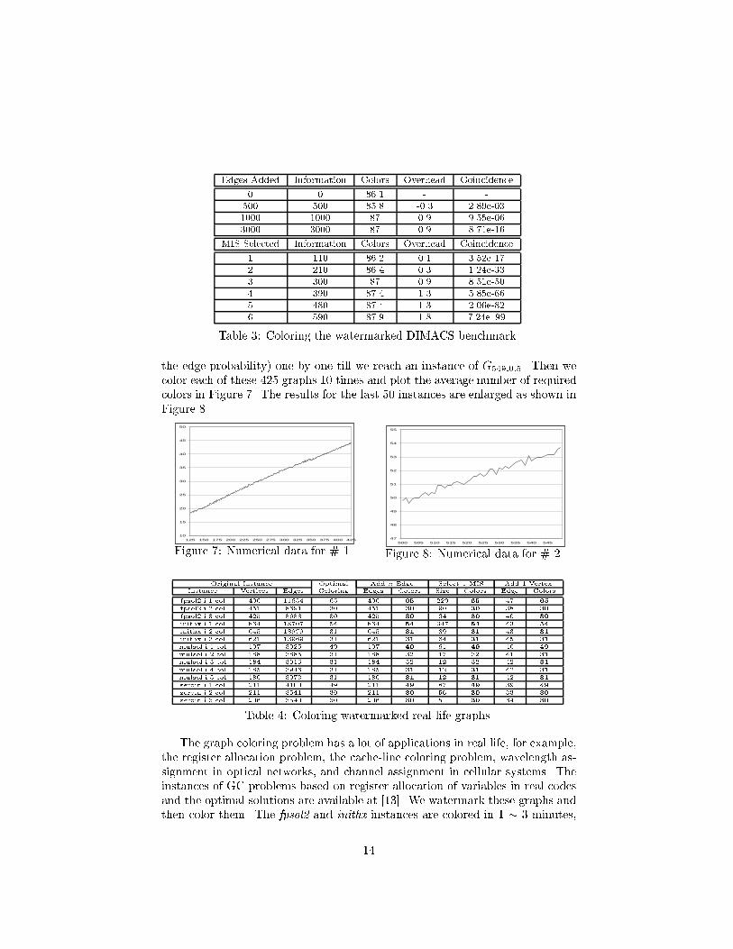
the edge probability) one by one till we reach an instance of G549;0:5. Then wecolor each of these 425 graphs 10 times and plot the average number of requiredcolors in Figure 7. The results for the last 50 instances are enlarged as shown inFigure 8
10
15
20
25
30
35
40
45
50
125 150 175 200 225 250 275 300 325 350 375 400 425
Figure 7: Numerical data for # 1.47
48
49
50
51
52
53
54
55
500 505 510 515 520 525 530 535 540 545
Figure 8: Numerical data for # 2.
Original Instance Optimal Add n Edge Select 1 MIS Add 1 VertexInstance Vertices Edges Coloring Edges Colors Size Colors Edge Colors
fpsol2.i.1.col 496 11654 65 496 65 229 65 47 65
fpsol2.i.2.col 451 8691 30 451 30 90 30 38 30
fpsol2.i.3.col 425 8688 30 425 30 64 30 40 30
inithx.i.1.col 864 18707 54 864 54 347 54 43 54
inithx.i.2.col 645 13979 31 645 31 89 31 43 31
inithx.i.3.col 621 13969 31 621 31 64 31 45 31
mulsol.i.1.col 197 3925 49 197 49 61 49 40 49
mulsol.i.2.col 188 3885 31 188 32 17 32 41 31
mulsol.i.3.col 184 3916 31 184 32 12 32 42 31
mulsol.i.4.col 185 3946 31 185 31 12 31 42 31
mulsol.i.5.col 186 3973 31 186 31 12 31 42 31
zeroin.i.1.col 211 4100 49 211 49 87 49 39 49
zeroin.i.2.col 211 3541 30 211 30 56 30 33 30
zeroin.i.3.col 206 3540 30 206 30 51 30 34 30
Table 4: Coloring watermarked real-life graphs.
The graph coloring problem has a lot of applications in real life, for example,the register allocation problem, the cache-line coloring problem, wavelength as-signment in optical networks, and channel assignment in cellular systems. Theinstances of GC problems based on register allocation of variables in real codesand the optimal solutions are available at [13]. We watermark these graphs andthen color them. The fpsol2 and inithx instances are colored in 1 � 3 minutes,
14

while the others are all colored in less than 0.5 minute. Table 4 reports thedetails. The �rst four columns shows the characteristic of the original graphand the known optimal solution; the next two are for technique #1, showing thenumber of edges (information in bits) being embedded and the overhead; fol-lowed by two columns for technique #2, where the Size columns are the numberof vertices in the selected MISes. The last two columns are for technique #3,where we compute the average edge probability of the original graph and addedges to keep this probability unchanged. Again, in almost all examples, thereis no overhead.
7 Conclusion
Most watermarking techniques lack formal analysis and their e�ectiveness solelyrelies on the experiments. In this paper, we build the �rst theoretical frameworkfor analyzing watermarking techniques. In particular, we select two of the mostimportant criteria for any e�ective watermark, namely high credibility and lowoverhead, as the basis of our analysis. We propose three watermarking techniquesfor the graph coloring problem, which are provably capable to provide highcredibility with at most 1-color overhead for large graphs. Asymptotic formulaeare given on the amount of information that can be embedded into the graphwithout too much overhead as well as the amount of information that shouldbe embedded to provide high credibility. Numerical data from simulation hasbeen analyzed and con�rms our results. Also, we watermark and then color alarge range of graphs from random graphs, DIMACS challenge graph to graphsgenerated from real life problems. With the same amount of run-time as for theoriginal graphs, for almost all instances, we obtain solutions of the same qualitywith no overhead.
References[1] H.Berghel and L.O'Gorman. Protecting ownership rights through digital watermarking. IEEE
computer, 29(7): 101-103, 1996.[2] B.Bollob�as. Random Graphs. Academic Press, London, 1985.[3] L.Boney, A.H.Tew�k, and K.N.Hamdy. Digital watermark for audio signals. International
Conference on Multimedia Computing and Systems, pp. 473-480, 1996.[4] I.J.Cox, J.Kilian, T.Leighton, and T.Shamoon. A secure, imperceptible yet perceptually
salient, spread spectrum watermark for multimedia. Southcon, pp. 192-197, 1996.[5] F. Hartung, and B. Girod, Digital watermarking of rae and compressed video. In Proceedings
of the SPIE-The Internation Society for Optical Engineering, volume 2952, pages 205-213, 1996.[6] A.B. Kahng, J. Lach, W.H. Magione-Smith, S. Mantik, I.L. Markov, M. Potkonjak, P. Tucker,
H. Wang and G. Wolfe. Watermarking Techniques for Intellectual Property Protection. 35thDesign Automation Conference Proceedings, pp. 776-781, 1998.
[7] D.Kirovski and M.Potkonjak. E�cient Coloring of a Large Spectrum of Graphs. 35th DesignAutomation Conference Proceedings, pp. 427-432, 1998.
[8] R. Nelson, and R.J. Wilson (Editors) Graph Colourings. Longman Scienti�c & Technical,Harlow,Essex, UK 1990.
[9] C. Podilchuk, W. Zeng, Perceptual watermarking of still images. IEEE Workshop on Multi-media Signal Processing, pp. 363-368, 1997.
[10] M.D.Swanson, B.Zhu, B.Chau, and A.H.Tew�k. Object-based transparent video watermarking.IEEE Workshop in Multimedia Signal Processing, pp. 369-374, 1997.
[11] M.M.Yeung, F.C.Mintzer, G.W.Braudaway, and A.R.Rao. Digital watermarking for high-quality imaging. IEEE Workshop on Multimedia Signal Processing, pp. 357-362, 1997.
[12] http://dimacs.rutgers.edu/[13] http://mat.gsia.cmu.edu/COLOR/instances.html
15

8 Appendices
8.1 Proof of Theorem 3.1
Theorem 3.1
Adding k(n) edges to a random graph Gn;p, for almost all Gn;p, limn!1
�0 � � = 1 i�
k(n) 2 !(n log n).
Proof:
In the original graph Gn;p, let b =1
1�pand � = d n
2 logb ne as given by (3). After
adding k(n) extra edges, the edge probability increases to p0 = p + 2kn(n�1)
, and b0 =1
1�p0, �0 = d n
2 logb0 ne.
�0 � � = d n
2 logb0 ne � d n
2 logb ne � n
2 logb0 n� n
2 logb n� 1 = logn (
b0
b)n=2 � 1
where b0
b= 1�p
1�p0= 1 + 2k=n(n�1)
(1�p)�2k=n(n�1):
It is clear that k(n) 2 O(n2), and further if k(n) 2 �(n2) then �0 � � ! 1 asn!1. Therefore,
limn!1
(b0
b)n2 = lim
n!1(1 +
2
1� p
k
n(n� 1))n2 = lim
n!1e
k(1�p)(n�1)
and
limn!1
�0 � � � lim
n!1logn (
b0
b)n=2 � 1 = lim
n!1
k
(1� p)(n� 1) lnn� 1
So, if k(n) 2 !(n log n), limn!1
�0 � � =1.
On the other hand, since
�0 � � = d n
2 logb0 ne � d n
2 logb ne � n
2 logb0 n+ 1� n
2 logb n= logn (
b0
b)n=2 + 1
similarly, we can see if k(n) 2 O(n log n), �0 � � will be bounded.
8.2 Proof of Theorem 3.3
Theorem 3.3 (arbitrarily high credibility)Adding k(n) edges to a random graph Gn;p, let E be the event that a random solutionto the original graph also satis�es all these k(n) extra constraints. Then for almost allGn;p, lim
n!1Prob[E ] = 0 if k(n) 2 !( n
logn).
Proof:
The event E is probabilistic equivalent to �xing a GC solution, then selecting k(n)pairs of disconnected vertices and each pair do not have the same color. For randomgraph Gn;p, each vertex has p(n � 1) neighbors, and if the graph is color by � =d n2 logb n
e colors as given by (3), in average there will be b2 logb nc vertices for eachcolor. Hence, when we select two disconnected vertices, the probability that they havedi�erent colors is 1 � b2 logb nc�1
q(n�1). Assuming that k(n) pairs of vertices are picked
independently, then the probability that the vertices in each pair are of di�erent colorsis (1� b2 logb nc�1
q(n�1))k(n).
i

limn!1
Prob[E ] = limn!1
(1� b2 logb nc � 1
q(n� 1))k(n) � lim
n!1(1� logb n
qn)k(n)
= limn!1
(1� logb n
qn)
qnlogb n
k(n) logb n
qn = limn!1
e�
k(n) logb n
qn
= 0 ( if k(n) 2 !(n
log n) = !(�):)
8.3 Proof of Theorem 4.2
Theorem 4.2 (arbitrarily high credibility with 1-color overhead)Given a random graph Gn;p, we select one MIS as in Figure 9. Let E be the event thatin a random solution, all vertices in this MIS have the same color and they are in theorder as speci�ed by Figure 4. Then lim
n!1Prob [E ] = 0. Furthermore, this introduces
at most 1-color overhead.
Proof:
For a random graph Gn;p, the technique in Figure 4 gives us a MIS of size logb nby Lemma 4.1. Given a �xed solution to Gn;p, event E has the same probability as:constructing all MISes of size logb n with a speci�c order and one randomly picked MIShas all its logb n vertices the same color.
From the Stirling formula:
k! = (k
e)kp2�ke�k
where 112k+1
< �k <1
12k, we have:
Prob[E ] =1
(nq)�(nq2)�����(nqlogb n�1)
(logb n)!
= (1
q)logb n(logb n�1)
2 (1
n)logb n�1(logb n)!
= (blogb n)logb n�1
2 (1
n)logb n�1(logb n)! = n
1�logb n
2 (logb n)!
= n1�logb n
2 (logb n
e)logb n
p2�logb ne
�logb n
=p2�nlogb ne
�logb n(logb n
epn)logb n
! 0 (n!1)where 1
12logb n+1< �logb n < 1
12logb n.
It costs exactly one color for the selected MIS, and coloring the remaining graphrequires no more than the number of colors for the original graph. Therefore, thisintroduces at most one extra color overhead.
8.4 Proof of Theorem 4.3
Theorem 4.3
Given a random graph Gn;p, if we select k(n) MISes as in Figure 9, assign each MISone color and color the rest of the graph, then the overhead is at most k(n) and on
average at least k(n)
2.
ii

Proof:
The �rst part is trivial from the fact that � is non-decreasing in terms of n.
By Lemma 4.1, the MIS is of size logb n. Assuming the message is random, afterwe cut this MIS from the original graph Gn;p, the remaining graph will still be randomwith n0 = n� logb n vertices and the same edge probability p. Therefore, from formula
(4) in section 3.2, we need �0 = d n0
2 logb n0e colors to color this remaining graph, taking
into account one more color for the selected MIS, we use a total of �0 + 1 colors tocolor the original graph Gn;p.
�0 + 1� � = d n0
2 logb n0e+ 1� d n
2 logb ne = d n� logb n
2 logb (n � logb n)e+ 1 � d n
2 logb ne
= d( n
2 logb n� 1
2)log(n�logb n)
ne+ 1� d n
2 logb ne
� d n
2 logb n� 1
2e+ 1� d n
2 logb ne
since log(n�logb n)n > 1
For a uniformly distributed real number x, Prob(dx� 12e = dxe) = 0:5. Therefore,
when we construct one MIS by Figure 9, we will introduce one extra color overheadwith probability at least 50%. And when we construct two MISes, for sure we willintroduce at least one-color-overhead since d�� 1e = d�e � 1. In general, when k(n)MISes are selected, the size of the remaining graph n0 � n� k logb n because the sizeof MIS decreases with the size of the graph. So
�0 + k(n)� � � d n
2 logb n� k(n)
2e+ 1� d n
2 logb ne � k(n)
2
8.5 Pseudo-code for Technique #2
Input: a graph G(V;E), a message M = m0m1 : : :
Output: new graph with message M embeddedAlgorithm:
current graph = original graph G(V;E);previous graph = current graph;MIS = �;do f if (current graph is empty)
f current graph = previous graph - MIS;previous graph = current graph;report MIS and reset MIS = �; g
if (current graph has more than 2 vertices or is connected)f �nd the vertex v corresponding to the next blog2 ncbits of M , where n is the size of the current graph;cut v and all its neighbors from the current graph;current graph = current graph - fv and its neighborsg;MIS = MIS + v;reorder the vertices in current graph;advance message M .
g else MIS = MIS + current graph;gwhile(M is not empty)
report the current graph;
Figure 9: Pseudo code for watermarking technique # 2.
iii