Embed Size (px)
Citation preview

Copyright 1997ASSET InterTech, Inc.Texas Instruments Inc.All Rights Reserved
Revision A31 Aug 1992Authors: Adam Sheppard, Giridhar V.
PRELIMINARY
Hierarchical ScanDescription LanguageSyntax Specification
ASSET InterTech,Inc.
i
Table of Contents1. Identification ............................................................................................................. 1
1.1. Product Statement............................................................................................... 11.2. Scope.................................................................................................................. 21.3. Important Notice .................................................................................................. 21.4. Nomenclature ...................................................................................................... 21.5. Related Documents ............................................................................................. 71.6. Constraints .......................................................................................................... 8
2. Introduction to Hierarchical Scan Description Language............................................ 92.1. Language Elements............................................................................................. 9
2.1.1. The VHDL Statement Subset......................................................................... 92.1.2. The Entity, the Package, and the Package Body ........................................... 9
2.2. The Entity Description for a Device...................................................................... 92.2.1. Generic Parameter ........................................................................................ 102.2.2. Logical Port Description................................................................................. 102.2.3. Use Statement(s) .......................................................................................... 102.2.4. Optional Device Description .......................................................................... 102.2.5. Optional Port Description(s)........................................................................... 102.2.6. Package Pin Mapping.................................................................................... 112.2.7. Scan Port Identification ................................................................................. 112.2.8. Device-Dependent Descriptions..................................................................... 112.2.9. Optional Data Registers(s)............................................................................. 122.2.10. Optional Symbol Table(s) .............................................................................. 122.2.11. Register Access............................................................................................. 142.2.12. Optional Register Information........................................................................ 142.2.13. Boundary Register Description ...................................................................... 152.2.14. Optional Boundary Register Symbol(s) .......................................................... 152.2.15. Optional Bus Description(s) ........................................................................... 152.2.16. Optional Constraint Description(s) ................................................................. 162.2.17. Optional Design Warning............................................................................... 16
2.3. The Entity Description for a Module ..................................................................... 162.3.1. Generic Parameter ........................................................................................ 172.3.2. Logical Port Description................................................................................. 182.3.3. Use Statement(s) .......................................................................................... 182.3.4. Optional Module Description.......................................................................... 182.3.5. Optional Port Description(s)........................................................................... 182.3.6. Package Pin Mapping.................................................................................... 182.3.7. Scan Port Identification ................................................................................. 182.3.8. Optional Member Description(s) .................................................................... 192.3.9. Optional Symbol Table Description(s)............................................................ 202.3.10. Optional Bus Description(s) ........................................................................... 202.3.11. Path Descriptions .......................................................................................... 202.3.12. Optional External Path Declaration(s)............................................................ 242.3.13. Static Path Declaration(s).............................................................................. 252.3.14. Optional Dynamic Path Declaration(s) ........................................................... 262.3.15. Optional Member Connections ...................................................................... 272.3.16. Path Requirements........................................................................................ 272.3.17. Optional Constraint Description(s) ................................................................. 302.3.18. Optional Design Warning............................................................................... 30
3. Using HSDL............................................................................................................... 313.1. Describing Architectures Above the Device Level................................................ 313.2. Describing a Board, Box, Subsystem, or System ................................................. 323.3. Describing a Multichip Module ............................................................................. 333.4. Describing a Backplane ....................................................................................... 333.5. Assigning a Name to a Subset of a Test Register ................................................ 34

ii
3.6. Assigning a Name to a Bus on a Board................................................................ 353.7. Assigning a Symbolic Name to a Value ............................................................... 353.8. Assigning Symbolic Names to a Test Register or Bus .......................................... 353.9. Preventing Illegal Hardware Conditions ............................................................... 363.10. Adding Descriptions to Each Item in the Entity..................................................... 363.11. Controlling Ad-Hoc Scan Path Multiplexing.......................................................... 36
4. Example HSDL Device Description........................................................................... 375. Example HSDL Module Descriptions......................................................................... 41
5.1. HSDL for General Demonstration Module............................................................ 415.2. HSDL for Figure 3-1 of IEEE Std 1149.1-1990..................................................... 425.3. HSDL for Figure 3-2 of IEEE Std 1149.1-1990..................................................... 435.4. HSDL for Figure 3-3 of IEEE Std 1149.1-1990..................................................... 445.5. HSDL for Fictional Module................................................................................... 45
A. Hierarchical Scan Description Language Syntax ....................................................... 49A.1. List of HSDL Statements ..................................................................................... 49
B. HSDL Standard VHDL Package Definitions............................................................... 102B.1. HSDL_device Standard VHDL Package............................................................... 102B.2. HSDL_module Standard VHDL Package ............................................................. 102

Revision A HSDL Syntax Specification
PRELIMINARY 1 31-Aug-1992
1.Identification
1.1. Product StatementDuring late 1989 and 1990, representatives of Hewlett-Packard developed and promoted alanguage for describing boundary-scan devices, called Boundary Scan Description Language5(BSDL). The intended applications of BSDL were as input to a test driver, as input to acompliance monitor, and as input to an automated boundary-scan synthesis tool. All threeintended applications are automated, utilizing software to drive, validate, or even create theboundary-scan hardware.
Also during this time, Texas Instruments released the ASSET Scan-Based Diagnostic System,10the first system to support IEEE Std 1149.1-1990. The first generation of ASSET usedConfiguration Files to describe 1149.1 devices, boards, and systems. ASSET ConfigurationFiles were given to HP to aid in the development of BSDL.
HP has done an excellent job in working with industry to fan out the BSDL requirementsspecifications and accept inputs for improvements. BSDL has become a de-facto standard, and15is supported by many ATE, CAE, and semiconductor vendors and customers.
BSDL focuses on describing only 1149.1 compliant devices. It does not address 1149.1 at theboard, system, or multi-chip module levels. BSDL also needs a few device-level features addedto better support interactive debug. Manipulating test registers as a stream of bits is not easy,and determining the values on device pin buses or on fields within test data registers by looking20at binary or hexadecimal output is impossible. ASSET 1.X Configuration Files, as simple as theywere, addressed this issue.
ASSET marketing and support personnel began being questioned about when ASSET wouldsupport BSDL. In addition, customers also began asking for enhancements to the ASSET 1.XConfiguration File language. They wanted compatibility with existing BSDL files to avoid rework,25and they wanted more flexibility to add convenience features for interactive use.
In response, Hierarchical Scan Description Language was created. It addresses a number ofdeficiencies in both BSDL and Configuration Files. HSDL supports all the features of BSDL forindustry compatibility, providing support for automatic test-pattern generation, validation, andsynthesis tools. HSDL also supports all the convenience features of Configuration Files,30providing the ability to describe boards, name subsets of test registers, create symbol tables fortest registers or fields that use symbolic, named values, prevent illegal states from beingestablished, and so forth.
In addition, HSDL supports new features that increase its powers in the areas covered by bothBSDL and Configuration Files. For automated tools, HSDL includes new features such as those35for describing different status values captured by a test register and designating them as "pass"or "fail" values. For interactive use, HSDL includes new features such as those for addingdescriptive text to each item in the entity.
HSDL is a strict superset of BSDL. All statements that are part of HSDL device entities but notpart of BSDL are optional. Thus, BSDL is acceptable input to an HSDL translator. HSDL device40entities can be made acceptable to a BSDL translator simply by feeding them to the BSDLtranslator and deleting all the new statements that cause syntax errors, with no loss or change inmeaning.
HSDL is similar to an ongoing effort in the EDIF Test Committee, which is seeking to define BST(Boundary-Scan Test) as an area of EDIF that will describe boundary-scan devices and boards.45Much of BST and its predecessor EBST has been incorporated into HSDL. BST includes netlistinformation (because EDIF does) and test vector information for the device and board being
Revision A HSDL Syntax Specification
PRELIMINARY 2 31-Aug-1992
described. These items were omitted from HSDL to keep it focused on the original spirit ofBSDL.
TI is supporting BSDL by making BSDL files available for TI devices, and has upgraded the first50generation of ASSET to take BSDL as an input. TI and Teradyne have jointly developed theSerial Vector Format (SVF) and have placed this specification in the public domain for review.The industry did not have a common serial vector format standard, and SVF was developed toaddress this problem. With the introduction of HSDL, TI continues its effort of working withindustry to develop or promote standard data formats that make it easier for customers to adopt551149.1.
1.2. ScopeThis document describes in detail the new statements of HSDL and their meaning. It does notdescribe BSDL, as many sources of information on BSDL already exist and HSDL does notchange any of the original BSDL statements in any way.60
1.3. Important NoticeThis document defines Texas Instruments' (TI) Hierarchical Scan Description Language (HSDL).Texas Instruments reserves the right to make changes to this document without notice. TIadvises its customers to obtain the latest version of the relevant information to verify that theinformation being relied upon is current.65
Although TI hereby expressly disclaims any and all warranties whatsoever regarding the HSDLSyntax Specification, TI has published this document with the intent that HSDL will be seriouslyconsidered and adopted, in whole, by the test and measurement and semiconductormarketplaces.
To obtain copies of the current HSDL Syntax Specification, please contact the Test Technology70Center of Texas Instruments:
Mailing Address: Test Technology CenterP.O. Box 869305M/S 8407Plano, TX 75086
Phone: (214) 575-2577X.400 E-mail Address: /ADMD=MCI/PRMD=TI/C=US/G=ADAM/S=SHEPPARDMCIMail ID: 5333075
TI welcomes all feedback in order to improve the HSDL Syntax Specification as necessary.Please direct comments to Adam Sheppard:
75Phone: (214) 575-2599X.400 E-mail Address: /ADMD=MCI/PRMD=TI/C=US/G=ADAM/S=SHEPPARDMCIMail ID: 5333075
This document is Copyright 1992, Texas Instruments Incorporated.
1.4. Nomenclature
ambiguous........................ Ambiguous values have combinations of don't-care bits such thattwo such values could be selected as a replacement for the same bitpattern.80
ASSET ............................ A design debug and verification tool from ASSET InterTech, Inc.
Revision A HSDL Syntax Specification
PRELIMINARY 3 31-Aug-1992
arithmetic operator........... A constraint operator that performs multiplication, division, addition,or subtraction of two values.
associative operator......... An arithmetic, logical, or relational operator whose left and rightoperands can be exchanged without altering the result.85
attribute............................. A VHDL attribute is a named item and associates some value withanother named object, such as the entity.
BIST .................................. Built-in self test.
BSDL ................................. Boundary-Scan Description Language. Hardware descriptionlanguage developed by Hewlett-Packard Company.90
bus .................................... A collection of bits from one or more test registers or buses, chosento represent a natural grouping of data in a design. An HSDL bus asdeclared in the BUS_COMPOSITION attribute.
cell..................................... An 1149.1 scan cell designed into a device. A BSDL constant thatdefines the characteristics of a scan cell.95
CLAMP .............................. A new instruction in 1149.1 Supplement A that shifts through theBYPASS register, but drives device outputs based on the contentsof the BOUNDARY register.
constraint.......................... An expression that is evaluated prior to each scan operation, thatdetermines if the values to be shifted into the hardware will violate a100design constraint and cause possible hardware damage. An HSDLconstraint as declared in the CONSTRAINTS attribute.
concatenated test registerA test register comprised of two or more other test registers.
configuration file .............. A file format used by ASSET 1.X to describe devices and modules.Two formats were used: device configuration files and module105configuration files. Each consisted of five different statement typesdescribing such things as test registers, instructions, register fields,members, paths, module buses, and constraints.
data-register scan............. A scan operation that includes shifting new data into test dataregisters from the TDI buffers and shifting captured data out into the110TDO buffers while the TAP controller is in Shift-DR state. The testcontroller automatically shifts a number of bits equal to thecombined length of the selected test data registers of all devices inthe scan path.
description........................ An HSDL or BSDL file containing an entity describing a unit under115test. Any comments attached to an item in the HSDL entity with a..._DESCRIPTION attribute to increase understandability.
device entity ..................... An HSDL device entity describes an 1149.1 device, with testregisters, instructions, and a TAP.
device under test.............. A unit under test that is a device.120
Revision A HSDL Syntax Specification
PRELIMINARY 4 31-Aug-1992
don't-care.......................... A BIT value representing a bit whose value does not matter.
DR scan............................. See data-register scan.
dynamic path .................... A set of controlled paths that may be attached to the TMS signal ofthe scan path or have their TMS lines forced high or low. Ahardware construct described by an HSDL DYNAMIC_PATH125attribute.
dynamic path case ........... A certain configuration of a dynamic path, where one of thecontrolled paths is attached to the TMS line.
entity ................................. An HSDL entity or entity identifier as defined in the BSDL entitystatement.130
external path..................... A connector of any type where TDO leaves the module and TDIreturns without a connection between. An item described by anHSDL EXTERNAL_PATH constant.
generic .............................. A parameter to the entity, used in BSDL and HSDL to contain thepackage type used in the design.135
HIGHZ................................ A new instruction in 1149.1 Supplement A that shifts through theBYPASS register, but places all three-state or bidirectional deviceoutputs in a high-impedance state.
HSDL ................................. Hierarchical Scan Description Language. A superset of BSDLdeveloped by Texas Instruments Incorporated.140
identifier............................ A sequence of characters used to name an object.
implementation-defined ... Behavior that is described as implementation-defined is subject tointerpretation by each implementation of a test controller. Each testcontroller may behave differently when an implementation-definedconstruct is used.145
in port................................ A port that describes an input pin.
inout port .......................... A port that describes a bidirectional pin.
instruction ........................ An HSDL instruction opcode described by the HSDLINSTRUCTION_OPCODE attribute.
instruction-register scan.. A scan operation that includes shifting new data into instruction150registers from the TDI buffers and shifting captured data out into theTDO buffers while the TAP controller is in Shift-IR state. The testcontroller automatically shifts a number of bits equal to thecombined length of the instruction registers of all devices in the scanpath.155
IR scan .............................. See instruction-register scan.
logical operator ................ A constraint operator that performs operations on individual bits of avalue.
Revision A HSDL Syntax Specification
PRELIMINARY 5 31-Aug-1992
LSB.................................... Least-significant bit. The bit whose binary value is 20.
member ............................. A device or module mounted on a module. An HSDL device or160module entity contained as a member within a module entity.
member connection ......... An HSDL CONNECTIONS attribute used to connect something toeach of the external paths of the members of a module.
module entity.................... An HSDL module entity describes an 1149.1 module, which containsother device and module entities arranged along a scan path.165
MSB................................... Most-significant bit. The bit whose binary value is 2n-1, where n isthe number of bits in the value.
net ..................................... A set of device pins that are all interconnected.
netlist ................................ A list of interconnections on a device or module. See net.
normal mode..................... A normal-mode instruction does not affect the functionality of a170device in any way.
operator ............................ The person performing a test. In the context of constraints, a wordor special symbol that represents a logical, relational, or arithmeticoperation to perform.
out port ............................. A port that describes an output pin.175
package............................. An HSDL package identifier declared in the PIN_MAP_STRINGconstant.
path ................................... An HSDL path declared in an STATIC_PATH, DYNAMIC_PATH, orEXTERNAL_PATH constant.
path entry.......................... Something that can be listed in a static path or dynamic path180declaration. A static path, dynamic path, external path, member, ormember's external path.
port.................................... Represents a named device pin. An HSDL port declared in thePORT statement.
primary scan path ............ A scan path that is a complete TDI-to-TDO connection from a TDI185input of the module to a TDO output of the module, including allmember devices, member modules, external paths, static paths, anddynamic paths that make up the primary scan path.
private instruction ............ An instruction opcode that performs proprietary or dangerousoperations when shifted into the instruction register. A private190instruction cannot be shifted in by the test controller.
pure test connector .......... A connector whose TAP_SCAN_CLOCK, TAP_SCAN_MODE, andTAP_SCAN_RESET ports are all in ports so that a test controllercan be plugged into it.
Revision A HSDL Syntax Specification
PRELIMINARY 6 31-Aug-1992
pure UUT connector......... A connector whose TAP_SCAN_CLOCK, TAP_SCAN_MODE, and195TAP_SCAN_RESET ports are all out ports so that a scannable UUTcan be plugged into it.
relational operator............ A constraint operator that compares the equality or ordering of twovalues.
reserved word................... A language element (identifier) that is used as part of the language200and that cannot be used to name an object in a declaration.
scan operation.................. An operation that manipulates the IEEE Std 1149.1 test bus toperform test operations.
scan path .......................... A serial TDI-to-TDO connection of devices and modules forming acomplete 1149.1 test bus.205
Scan Path Linker .............. A device (SN74ACT8997) from Texas Instruments that multiplexessecondary scan paths in and out of the primary scan path.
selected test connector.... The test connector that the test controller is plugged into for theduration of the test.
semantics.......................... Rules that specify the restrictions and meaning of a computer210language.
standard practice ............. Rules followed when writing VHDL for use in BSDL or HSDL entitiesthat simplify the computer programs that translate BSDL and HSDL.
static path ......................... A serial TDI-to-TDO connection of member devices, membermodules, and scan paths that all share the same TAP control215signals. A scan path described by an HSDL STATIC_PATHconstant.
symbol .............................. An identifier that represents a list of one or more numbers orpatterns. An HSDL symbol declared in the SYMBOL_TABLEconstant.220
symbol table ..................... A collection of related symbols. An HSDL symbol table declared inthe SYMBOL_TABLE constant.
syntax................................ The rules that describe what characters to write to form a program.The program is meaningless without semantics.
TAP control signals.......... For the purposes of this specification, the TAP control signals are225Test Clock (TCK), described by the TAP_SCAN_CLOCK attribute;Test Mode Select (TMS), described by the TAP_SCAN_MODEattribute, and Test Reset (TRST), described by theTAP_SCAN_RESET attribute.
TDI symbol........................ A symbol that may be used to represent a value to shift into a UUT,230but not to represent a value that is shifted out.
TDO symbol...................... A symbol that may be used to represent a value shifted out of aUUT, but not to represent a value to shift in.

Revision A HSDL Syntax Specification
PRELIMINARY 7 31-Aug-1992
test connector .................. A connector that a test controller can be plugged into. See pure testconnector.235
test controller ................... The computer system, hardware, and/or software used to test theunit under test by applying stimuli and observing the response.
test mode .......................... A test-mode instruction affects the functionality of a device in someway, usually by overriding the device outputs or the system logicinputs.240
test register....................... An HSDL test register declared in the HSDL REGISTER_ACCESSattribute.
undefined.......................... Behavior that is described as undefined causes unpredicablebehavior in a test controller. An HSDL description may not rely onundefined behavior in a construct.245
unit under test .................. The HSDL entity, either a device or module, that is being tested bythe test controller.
user-defined package....... A BSDL package and package body that defines cells for use in theBOUNDARY_REGISTER attribute.
UUT ................................... See unit under test.250
UUT connector ................. A connector that a scannable UUT can be plugged into. See pureUUT connector.
VHDL ................................. VHSIC Hardware Description Language
VHSIC ................................ Very High Speed Integrated Circuit
violated constraint ........... A constraint that evaluates true. A violated constraint indicates that255a hardware design constraint would be violated, resulting in possibledamage to the unit under test.
1.5. Related DocumentsAdvanced Logic and Bus Interface Logic. Texas Instruments, 1991.
ASSET Scan-Based Diagnostics User's Guide. Texas Instruments, 1991.260
HP Boundary-Scan Tutorial and BSDL Reference Guide. Hewlett-Packard Company, 1990.
IEEE Std 1149.1-1990, Test Access Port and Boundary-Scan Architecture. IEEE, 1990.
IEEE Std 1149.1-1990 Supplement A. IEEE, 1992.
IEEE Std 1149.1-1990 Unofficial Supplement B, Boundary-Scan Description Language. 1149.1BSDL Working Group, 1992.265
IEEE Std 1076-1987, VHDL Language Reference Manual. IEEE, 1987.
Revision A HSDL Syntax Specification
PRELIMINARY 8 31-Aug-1992
1.6. ConstraintsHSDL supports only IEEE Std 1149.1-1990 compliant devices and modules.
A great deal of leniency is provided when describing modules, as allowed by 1149.1. Somepathologically complex modules cannot be described by HSDL in the interests of keeping the270language manageable. Fully describing all modules requires a netlist for the scan paths and asimulation model for the dynamic scan paths, which is considered beyond the scope of HSDL.
The language is designed in the spirit of BSDL, and hence the pros and cons of BSDL syntaxremain.
HSDL may undergo changes based on the inputs received from the industry when this document275is circulated.
Revision A HSDL Syntax Specification
PRELIMINARY 9 31-Aug-1992
2.Introduction to Hierarchical Scan Description Language
2.1. Language Elements
2.1.1. The VHDL Statement Subset280
HSDL employs the same subset of VHDL statements used by BSDL. However, the VHDLstatements are used in more flexible ways in HSDL than in BSDL. For example, BSDL onlyattaches attributes to the entity. HSDL attaches attributes to the entity, the ports, and toSymbol Table and Path constants.
2.1.2. The Entity, the Package, and the Package Body285
These three different VHDL items are used in the same manner in HSDL as they are inBSDL. HSDL has two types of entities, however: device entities and module entities. Adevice entity describes an 1149.1 device, with test registers, instructions, and a TAP. Amodule entity describes an 1149.1 module, which contains other device and module entitiesarranged along a scan path.290
A user-defined package for creating new cell types is of no use in a module entity, so amodule entity cannot contain user-defined packages.
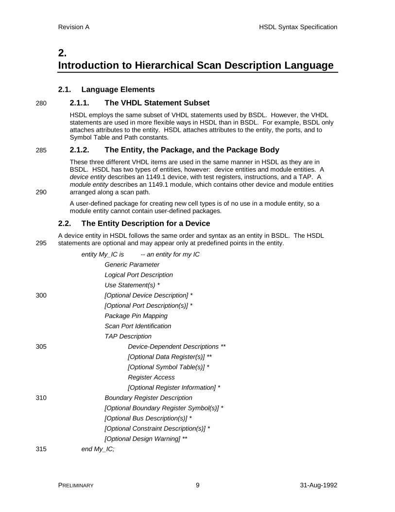
2.2. The Entity Description for a DeviceA device entity in HSDL follows the same order and syntax as an entity in BSDL. The HSDLstatements are optional and may appear only at predefined points in the entity.295
entity My_IC is -- an entity for my ICGeneric ParameterLogical Port DescriptionUse Statement(s) *[Optional Device Description] *300[Optional Port Description(s)] *Package Pin MappingScan Port IdentificationTAP Description
Device-Dependent Descriptions **305[Optional Data Register(s)] **[Optional Symbol Table(s)] *Register Access[Optional Register Information] *
Boundary Register Description310[Optional Boundary Register Symbol(s)] *[Optional Bus Description(s)] *[Optional Constraint Description(s)] *[Optional Design Warning] **
end My_IC;315
Revision A HSDL Syntax Specification
PRELIMINARY 10 31-Aug-1992
An asterisk (*) designates areas of HSDL that are new or that were enhanced from BSDL. Twoasterisks (**) designate areas of HSDL that are BSDL but that were not completely discussed inthe HP Boundary-Scan Tutorial and BSDL Reference Guide.
The order of elements shown above is a required standard practice in order to simplify non-VHDL applications, like BSDL or HSDL translators. Each element of the entity is examined and320discussed in the subsections that follow.
2.2.1. Generic ParameterUnchanged from BSDL. See generic (BSDL) in the HP Boundary-Scan Tutorial and BSDLReference Guide. The generic parameter is mandatory.
2.2.2. Logical Port Description325
Unchanged from BSDL. See port (BSDL) in the HP Boundary-Scan Tutorial and BSDLReference Guide. The port statement is mandatory.
2.2.3. Use Statement(s)The use statement is primarily unchanged from BSDL. See use (BSDL) in the HPBoundary-Scan Tutorial and BSDL Reference Guide. The statement use330STD_1149_1_1990.all; is mandatory and must appear first, followed by the optional user-defined packages.
A new package has been defined for HSDL device entities that declares all attributes andsubtypes used by a device entity. In addition, it identifies the entity as an HSDL device, andnot simply a BSDL device. The new package is HSDL_device, as shown in this example.335
use HSDL_device.all; -- identifies the entity as a device with HSDL extensions
2.2.4. Optional Device DescriptionThis optional statement describes the device. It appears primarily for documentationpurposes. Ideally, it should describe the functionality of the device in sufficient detail tomeet the requirements for documenting devices found in Chapter 12 of IEEE Std 1149.1-3401990. As a description, it may be displayed by interactive tools or by the test controller itselfas a description of the device under test.
attribute DEVICE_DESCRIPTION of ttl74bct8374 : entity is "SN74BCT8374 is a Scan Test Devices with Octal D-Type Edge-Triggered " & "Flip-Flops. In normal mode, on the positive transition of CLK the Q " &345 "outputs take on the logic levels setup up at the D inputs. The " & "output enable OC_NEG is used to place the Q outputs in the " & "high-impedance state, but does not affect the internal operations " & "of the flip-flop.";
2.2.5. Optional Port Description(s)350
Next comes optional statements for describing the ports of the device. The same syntax isused in the HSDL module entity for describing the ports of the module. The normal functionof each port should be described in sufficient detail so that the operator can understand howthe device normally operates.
Revision A HSDL Syntax Specification
PRELIMINARY 11 31-Aug-1992
Descriptions need not be supplied for the ports identified as scan ports by the355TAP_SCAN_IN, TAP_SCAN_OUT, TAP_SCAN_CLOCK, TAP_SCAN_MODE, andTAP_SCAN_RESET attributes (see Scan Port Identification). The description of these portsis already known and is described in full by IEEE Std 1149.1-1990. Suitable descriptions aresynthesized by the HSDL translator for these ports if no description has been supplied forthem.360
attribute PORT_DESCRIPTION of OC_NEG : signal is "Output control of the device. All pins on the output bus Q can be " & "set to high-impedance by placing a 1 on the OC_NEG pin. Disabling " & "the output bus Q has no effect on the internal operation of the " & "flip-flops.";365
2.2.6. Package Pin MappingUnchanged from BSDL. See attribute PIN_MAP (BSDL) and constant-(entity) (BSDL) in theHP Boundary-Scan Tutorial and BSDL Reference Guide. The PIN_MAP attribute ismandatory and must appear first, followed by one or more PIN_MAP_STRING constants.
2.2.7. Scan Port Identification370
Unchanged from BSDL. See attribute TAP_SCAN_CLOCK (BSDL), attribute TAP_SCAN_IN(BSDL), attribute TAP_SCAN_MODE (BSDL), attribute TAP_SCAN_OUT (BSDL), andattribute TAP_SCAN_RESET (BSDL) in the HP Boundary-Scan Tutorial and BSDLReference Guide. The statements may appear in any order. All but the TAP_SCAN_RESETattribute are required.375
2.2.8. Device-Dependent DescriptionsAll device-dependent descriptions are retained unchanged from BSDL. See attributeINSTRUCTION_LENGTH (BSDL), attribute INSTRUCTION_OPCODE (BSDL), attributeINSTRUCTION_CAPTURE (BSDL), attribute INSTRUCTION_DISABLE (BSDL), andattribute INSTRUCTION_PRIVATE (BSDL) in the HP Boundary-Scan Tutorial and BSDL380Reference Guide. The INSTRUCTION_LENGTH attribute is mandatory and must appearfirst, followed by the mandatory INSTRUCTION_OPCODE attribute and the mandatoryINSTRUCTION_CAPTURE attribute. The optional INSTRUCTION_DISABLE andINSTRUCTION_PRIVATE attributes may appear next in any order. In addition, the recentlyintroduced INSTRUCTION_GUARD attribute of BSDL is also available.385
Private instructions identified by the INSTRUCTION_PRIVATE attribute cannot be shiftedinto the device using HSDL. Private instructions invoke proprietary or dangerous testoperations in the device and cannot safely be used.
The optional INSTRUCTION_GUARD attribute of BSDL identifies an opcode that places theBypass Register between TDI and TDO, and drives the outputs of the device using the390previous contents of the Boundary-Scan Register. This is the behavior defined by theCLAMP instruction of IEEE Std 1149.1-1990 Supplement A. This statement identifies theopcode to software. An example of this type of statement appears in the BSDL for the BCToctals from Texas Instruments.
attribute INSTRUCTION_GUARD of ttl74bct8374 : entity is "SETBYP";395
The optional INSTRUCTION_NORMAL and INSTRUCTION_TEST attributes of BSDLidentify an opcode as either a normal-mode or test-mode instruction. Normal-modeinstructions do not affect the normal operation of the device in any way. Test-modeinstructions affect the normal operation, but the exact effect is unspecified. All or part of thenormal operation of the device is suspended and replaced with a test operation.400
The instructions BYPASS, SAMPLE, IDCODE, and USERCODE, defined by 1149.1, mustbe normal-mode instructions and do not need to be listed in the INSTRUCTION_NORMALattribute. The instructions EXTEST, INTEST, RUNBIST, HIGHZ, and CLAMP, defined by
Revision A HSDL Syntax Specification
PRELIMINARY 12 31-Aug-1992
1149.1 and Supplement A, must be test-mode instructions and do not need to be listed in theINSTRUCTION_TEST attribute. If an instruction is not defined by 1149.1 and is not listed in405either the INSTRUCTION_NORMAL or INSTRUCTION_TEST attributes, its effect on thehardware is unknown.
attribute INSTRUCTION_NORMAL of ttl74bct8374 : entity is "BYPASS, SAMPLE, READBN, CELLTST, SCANCN";
attribute INSTRUCTION_TEST of ttl74bct8374 : entity is410 "EXTEST, INTEST, TRIBYP, SETBYP, RUNT, READBT, TOPHIP, SCANCT";
An optional HSDL statement, INSTRUCTION_DESCRIPTION, follows the BSDL instructionstatements and can be used to provide descriptions of each instruction listed in theINSTRUCTION_OPCODE attribute. The descriptions may be displayed by the testcontroller to help the operator understand the purpose and function of each instruction.415
Descriptions need not be supplied for the standard instructions required by IEEE Std 1149.1-1990 and by Supplement A. These instructions include EXTEST, SAMPLE/PRELOAD,BYPASS, INTEST, RUNBIST, IDCODE, USERCODE, CLAMP, and HIGHZ. The descriptionof these instructions is already known and is described in full by IEEE Std 1149.1-1990.Suitable descriptions are synthesized by the HSDL translator for these instructions if no420description has been supplied for them. If instruction descriptions are used, it isrecommended that descriptions for INTEST and RUNBIST be supplied rather thansynthesized, as the operation of these instructions can vary from device to device.
attribute INSTRUCTION_DESCRIPTION of My_IC : entity is "BYPASS ('Select BYPASS register in normal mode.')," &425 "EXTEST ('Select Boundary-Scan register in test mode; control device" & "inputs and outputs using the contents of the Boundary.')," & "SAMPLE ('Select Boundary-Scan register in normal mode; sample " & "device inputs and outputs into the Boundary.')";
2.2.9. Optional Data Registers(s)430
Unchanged from BSDL. See attribute IDCODE_REGISTER (BSDL) and attributeUSERCODE_REGISTER (BSDL) in the HP Boundary-Scan Tutorial and BSDL ReferenceGuide. The optional IDCODE_REGISTER attribute must appear first, followed by theoptional USERCODE_REGISTER attribute.
2.2.10. Optional Symbol Table(s)435
Next the optional HSDL statements describing symbol tables may appear. Symbol tablesare groups of related symbol names. Each symbol name stands for one or more symbolvalues.
Symbol tables are useful for describing values by name rather than by number. IEEE Std1149.1-1990 already contains one example of a test register with an associated symbol440table: the instruction register. The standard never refers to "instruction 0"; instead it refersto "the EXTEST instruction". Other test registers or subsets of test registers often havenamed opcodes defined in the data sheet to describe the possible values in a mnemonicway.
Symbol tables are defined separately from the elements (test registers, buses, ports) that445they are associated with. If more than one test register in the entity uses the same opcodes,only one symbol table needs to be defined. That symbol table is then associated with eachof the test registers.
constant BCR_Opcodes : SYMBOL_TABLE :=-- symbol (value, ..., value)450 "SAMTOG (00)," & "PRPG (01)," & "PSA (10)," & "PSAPRPG (11)";
Revision A HSDL Syntax Specification
PRELIMINARY 13 31-Aug-1992
Multiple symbol tables may be created. The symbol table itself must be defined before any455of the attributes for it, because all the attributes refer to both the symbol table name and thesymbol names. The optional attributes for a symbol table may appear in any order followingthe symbol table.
Consider the uses for symbols. Symbols can be used in place of values being shifted intothe device, and symbols could be displayed in place of values shifted out of the device. This460suggests two possible types of symbols: symbols that can be shifted in and symbols that canbe shifted out. HSDL allows symbols to be classified as used only for shifting in(SYMBOL_OF_TDI), only for shifting out (SYMBOL_OF_TDO), or both (the default).
If a symbol name is not listed as a SYMBOL_OF_TDI or as a SYMBOL_OF_TDO for thesymbol table, it is considered to be both. The symbol can be used to represent a value to465shift into the device, and it can be displayed instead of a value shifted out of the device.
Why make this distinction? The 1149.1 standard contains a precedent: the instructionregister captures and shifts out a status value, but the value shifted into the instructionregister and latched is an instruction. Two different types of patterns with two totally differentmeanings are thus used by the instruction register. The status values captured and shifted470out are SYMBOL_OF_TDO, whereas the instructions shifted in and latched areSYMBOL_OF_TDI.
constant INSTRUCTIONS : SYMBOL_TABLE := "EXTEST (000)," & "SAMPLE (001)," &475 "BYPASS (1XX, 01X)," & "GOOD_STATUS (001)," & "BAD_STATUS (XX0)";attribute SYMBOL_OF_TDI of INSTRUCTIONS : constant is "EXTEST, SAMPLE, BYPASS";480attribute SYMBOL_OF_TDO of INSTRUCTIONS : constant is "GOOD_STATUS, BAD_STATUS";
Symbols designated SYMBOL_OF_TDO (either explicitly, or by defaulting to both TDI/TDO)cannot have ambiguous values. Ambiguous values have combinations of don't-care bitssuch that two symbols could be selected as a replacement for the same bit pattern. If TDO485symbols were allowed to be ambiguous, the test controller would potentially need to selectan infinite number of symbols for replacement, and thus the output would appear as a longlist of symbol names rather than just one.
Descriptions can be associated with each symbol. The descriptions should indicate thepurpose, function, and meaning of the symbol. The test controller may display this490description to help the operator select a symbol for shifting in, or interpret the meaning of asymbol that has been shifted out.
attribute SYMBOL_DESCRIPTION of BCR_Opcodes : constant is-- symbol (description) "SAMTOG ('Samples device inputs on input bus; toggles device outputs " &495 "from output bus.')," & "PRPG ('Conducts 16-bit Pseudo-Random Pattern Generation using the " & "contents of the input and output buses of the Boundary-Scan " & "register as an initial value. The Q outputs of the device " & "will be set to the value in the output bus. A new pattern " &500 "is generated on each TCK in Run-Test/Idle state.')," & "PSA ('Conducts 16-bit Parallel Signature Analysis using the " & "contents of the input and output buses of the Boundary-Scan " & "register as an initial value. The Q outputs of the device " & "will be set to the value in the output bus. A new checksum" &505 "is generated on each TCK in Run-Test/Idle state.')," & "PSAPRPG('Simultaneous 8-bit PSA on the D inputs and 8-bit PRPG on " & "the Q outputs.')";
Finally, a TDO or TDI/TDO symbol may be designated as the "default" TDO symbol. Thatsymbol will be displayed when no symbol's values directly match the bit pattern shifted out.510
attribute SYMBOL_DEFAULT of BIT_RESULTS : constant is "BIT_FAILED";
Revision A HSDL Syntax Specification
PRELIMINARY 14 31-Aug-1992
2.2.11. Register AccessUnchanged from BSDL. See attribute REGISTER_ACCESS (BSDL) in the HP Boundary-Scan Tutorial and BSDL Reference Guide. The REGISTER_ACCESS attribute ismandatory.515
2.2.12. Optional Register InformationHSDL provides the ability to define several additional types of information about the testregisters in a device. Test register concatenation, symbol tables, descriptions, Capture-DRvalues, Test-Logic-Reset values, and privacy can all be described. The new attributes canoccur in any order following the REGISTER_ACCESS attribute.520
A major deficiency of BSDL from a data-integrity viewpoint is its inability to describeconcatenated test registers. This hardware construct, where a third test register is formedfrom two other test registers (for example), is allowed by IEEE Std 1149.1-1990. However,in BSDL the third test register must be described as a completely separate register, sharingno hardware whatsoever. Conflicts can arise between what the test controller believes is525currently in the hardware and what the hardware believes is currently in the hardware.
attribute REGISTER_COMPOSITION of My_IC : entity is-- reg (reg, reg[bit], reg[bit,bit], ...) "BCR (REPS[1], REPS[3])," & "EMUL (REPS[5,12])";530
Each test register may have a symbol table associated with it, providing a set of symbolsthat can be shifted into the test register and used to represent values shifted out of the testregister.
attribute REGISTER_SYMBOLS of My_IC : entity is-- reg (symbol_table)535 "BCR (BCR_SYMBOLS)," & "EMUL (EMUL_SYMBOLS)";
Each test register can have a description associated with it.attribute REGISTER_DESCRIPTION of ttl74bct8374 : entity is-- reg (description)540 "BOUNDARY ('The Boundary-Scan register contains the cells attached " & "to the pins of the device.')," & "BYPASS ('The BYPASS register is a one-bit register that always " & "loads a 0 in the Capture-DR state. It is used to speed " & "up scanning to the UUT when a device is not used during " &545 "a test.')," & "BCR ('The Boundary Control Register is a design-specific " & "test data register used to specify the test operation - " & "PSA, PRPG - that will be performed by the RUNT " & "instruction.')";550
If the values captured by a test register in the Capture-DR state can be considered statusvalues, they can be placed in the REGISTER_CAPTURE attribute. Good and bad statusvalues can be identified, along with a description of the value. The description may bedisplayed for the operator to better understand the cause of success or failure.
attribute REGISTER_CAPTURE of ttl74bct8374 : entity is555-- reg (capturevalue, pass/fail, description) "BYPASS (0, pass, 'The BYPASS register is working correctly.')," & "EMUL (OKON, pass, 'The Emulation logic is working correctly; " & "emulation is enabled.')," & "EMUL (OKOFF, pass, 'The Emulation logic is working correctly; " &560 "emulation is disabled.')," & "EMUL (ERROR, fail, 'The Emulation logic is not working.')";

Revision A HSDL Syntax Specification
PRELIMINARY 15 31-Aug-1992
If a test register loads a constant value during Test-Logic-Reset, that value can be listed inthe REGISTER_RESET attribute. This is a data integrity feature of HSDL.
attribute REGISTER_RESET of ttl74bct8374 : entity is565-- reg (resetvalue) "INSTRUCTION (BYPASS)," & "BCR (PSA)";
2.2.13. Boundary Register DescriptionUnchanged from BSDL. See attribute BOUNDARY_CELLS (BSDL), BOUNDARY_LENGTH570(BSDL), and BOUNDARY_REGISTER (BSDL) in the HP Boundary-Scan Tutorial and BSDLReference Guide. These statements are mandatory and must appear in the order they arelisted here.
2.2.14. Optional Boundary Register Symbol(s)The optional HSDL BOUNDARY_SYMBOLS attribute may appear following all BSDL575boundary register statements. The BOUNDARY_SYMBOLS attribute is used to associatesymbol tables with certain types of cells attached to ports of the device. For example, a cellon a control pin could have a symbol table associated with it that defined ENABLE andDISABLE values.
attribute BOUNDARY_SYMBOLS of ttl74bct8374 : entity is580 "CLK (input, clk_symbols)," & "OC_NEG (input, oc_symbols)";
2.2.15. Optional Bus Description(s)The optional HSDL bus descriptions define buses, logical groupings of subsets of bits fromone or more test registers or buses. The most common use for buses in a device is to define585the fields contained within various test registers. For example, the IdCode Register consistsof version number, part number, and manufacturer fields. Each of these test registersubsets could be described using a bus.
attribute BUS_COMPOSITION of My_IC : entity is "version[4] (idcode[31,28])," &590 "part_number[16] (idcode[27,12])," & "manufacturer[11] (idcode[11, 1])";
attribute BUS_COMPOSITION of ttl74bct8374 : entity is-- bus[length] (reg, reg[bit], reg[bit,bit], ...) "inputs[8] (BOUNDARY[ 8,15])," &595 "outputs[8] (BOUNDARY[ 0, 7])," & "aux[2] (BOUNDARY[16,17])," & "lfsr[16] (BOUNDARY[ 0,15])";
A bus may have a symbol table associated with it. Again using the IdCode Register as anexample, the manufacturer field could have a large number of symbols associated with it,600describing the manufacturers.
attribute BUS_SYMBOLS of My_IC : entity is "manufacturer (List_Of_Manufacturers)";
attribute BUS_SYMBOLS of ttl74bct8374 : entity is-- bus (symbol_table)605 "aux (AUX_SYMBOLS)";

Revision A HSDL Syntax Specification
PRELIMINARY 16 31-Aug-1992
Each bus in the design can optionally have a description associated with it.attribute BUS_DESCRIPTION of My_IC : entity is "version ('The version number of the device.')," & "part_number ('The part number of the device.'), " &610 "manufacturer ('The manufacturer''s JEDEC code.')";
attribute BUS_DESCRIPTION of ttl74bct8374 : entity is-- bus (description) "inputs ('The eight cells of the Boundary-Scan register " & "that are connected to the D inputs are combined " &615 "to form the input bus.')," & "outputs ('The eight cells of the Boundary-Scan register " & "that are connected to the Q outputs are " & "combined to form the output bus.')," & "aux ('The two cells of the Boundary-Scan register " &620 "that are connected to the CLK and OC_NEG pins " & "are combined to form the aux bus.')," & "lfsr ('A bus used by the bcr.')";
2.2.16. Optional Constraint Description(s)The design of hardware inevitably involves some constraints, illegal conditions that cannot625be established without unpredictable or damaging results. Constraints consist of logical andrelational expressions that are evaluated before each scan operation. If any of theconstraints are TRUE, an illegal condition has been created and no scanning can beperformed until the constraint is FALSE.
attribute CONSTRAINTS of My_IC : entity is630-- constraint (expression) "shared_cells (BCR = SAMTOG and EMUL = STEP)," & "bad_device (BYPASS = 1)";
Constraints may also have a description associated with them. The description may bedisplayed by the test controller when the constraint has been violated to aid the operator in635correcting the problem.
attribute CONSTRAINT_DESCRIPTION of My_IC : entity is-- constraint (description) "shared_cells ('Physical cells are shared by the Boundary Control " & "Register and the EMUL emulation register.')," &640 "bad_device ('The device fails if BYPASS is a 1 (not true)!')";
2.2.17. Optional Design WarningUnchanged from BSDL. The DESIGN_WARNING attribute is not discussed in the BSDLSyntax chapter of the HP Boundary-Scan Tutorial and BSDL Reference Guide, but isdescribed in the Introduction to BSDL chapter under the section Miscellaneous Declarations.645This statement is optional.
2.3. The Entity Description for a ModuleA module is defined as a collection of devices and other modules whose TAP ports areconnected to define a scan path. Since modules can contain other modules as members, ahierarchy is formed (hence the name Hierarchical Scan Description Language). The simplest650module represents a board containing one or more devices connected into a single scan path.More complicated modules can represent multi-chip modules, backplanes, boxes, subsystems,or entire systems.
A module entity in HSDL uses much of the same syntax as a device entity. New statementshave been added to list the device and module entities mounted on the module entity and to655describe how these member entities are interconnected. Existing BSDL statements have beenremoved where they did not apply to the description of modules.
A module does not have to directly represent a physical board, box, etc. A module entity can beused to define any collection of members that is convenient. Usually, the most convenient

Revision A HSDL Syntax Specification
PRELIMINARY 17 31-Aug-1992
module entity is one that corresponds directly to a real board, but occasionally other divisions660may be useful.
Modules and devices have many similiarities. Both have ports, different packaging options, TestAccess Port(s), symbol tables, buses, and constraints. The main differences are that a deviceconsists of test registers connected in a certain way and controlled by instructions, whereas amodule consists of member devices and modules connected in a certain way and controlled by665scan paths.
entity My_Board is -- an entity for my board
Generic Parameter
Logical Port Description
Use Statement(s) *670
[Optional Module Descriptions] *
[Optional Port Description(s)] *
Package Pin Mapping
Scan Port Identification
[Optional Member Description(s)] *675
[Optional Symbol Table Description(s)] *
[Optional Bus Description(s)] *
Path Description(s) *
[ Optional External Path Declaration(s)] *
Static Path Declaration(s) *680
[ Optional Dynamic Path Declaration(s)] *
[ Optional Member Connections] *
[Optional Constraint Description(s)] *
[Optional Design Warning] **
end My_Board;685
An asterisk (*) designates areas of HSDL that are new or that were enhanced from BSDL. Twoasterisks (**) designate areas of HSDL that are BSDL but that were not completely discussed inthe HP Boundary-Scan Tutorial and BSDL Reference Guide.
In a sense, all the statements of a module entity are new, because BSDL could not describemodules. However, the syntax and meaning of many of the statements is the same. For this690reason, an HSDL module entity cannot be converted into BSDL, because no equivalent BSDLexists.
The order of elements shown above is a required standard practice in order to simplify non-VHDL applications, like BSDL or HSDL translators. Each element of the entity is examined anddiscussed in the subsections that follow.695
2.3.1. Generic ParameterUnchanged from BSDL. See generic (BSDL) in the HP Boundary-Scan Tutorial and BSDLReference Guide. The generic parameter is mandatory.

Revision A HSDL Syntax Specification
PRELIMINARY 18 31-Aug-1992
2.3.2. Logical Port DescriptionUnchanged from BSDL. See port (BSDL) in the HP Boundary-Scan Tutorial and BSDL700Reference Guide. The port statement is mandatory.
2.3.3. Use Statement(s)The use statement is primarily unchanged from BSDL. See use (BSDL) in the HPBoundary-Scan Tutorial and BSDL Reference Guide. The statement useSTD_1149_1_1990.all; is mandatory and must appear first, followed by the HSDL module705package.
HSDL modules cannot use user-defined packages. These packages only contain celldefinitions for the boundary register, and a module does not have a boundary register.
A new package has been defined for HSDL module entities that declares all attributes andsubtypes used by a module entity. In addition, it identifies the entity as an HSDL module.710The new package is HSDL_module, as shown in this example.
use HSDL_module.all; -- identifies the entity as an HSDL module
2.3.4. Optional Module DescriptionThis optional statement describes the module. It appears primarily for documentationpurposes. Ideally, it should describe the functionality of the module in sufficient detail to715help the test engineer or operator understand the function, purpose, and usage of themodule. As a description, it may be displayed by interactive tools or by the test controlleritself as a description of the module under test.
attribute MODULE_DESCRIPTION of gdm: entity is "The General Demonstration Module (GDM) is an example board that was " &720 "designed to demonstrate some of the capabilities of an 1149.1 UUT.";
2.3.5. Optional Port Description(s)Same as the HSDL device entity.
2.3.6. Package Pin MappingUnchanged from BSDL. See attribute PIN_MAP (BSDL) and constant-(entity) (BSDL) in the725HP Boundary-Scan Tutorial and BSDL Reference Guide. The PIN_MAP attribute ismandatory and must appear first, followed by one or more PIN_MAP_STRING constants.
2.3.7. Scan Port IdentificationSyntax is unchanged from BSDL. See attribute TAP_SCAN_CLOCK (BSDL), attributeTAP_SCAN_IN (BSDL), attribute TAP_SCAN_MODE (BSDL), attribute TAP_SCAN_OUT730(BSDL), and attribute TAP_SCAN_RESET (BSDL) in the HP Boundary-Scan Tutorial andBSDL Reference Guide. The statements may appear in any order. All but theTAP_SCAN_RESET attribute are required.
IEEE Std 1149.1-1990 compliant devices have a single Test Access Port (TAP). Modules,however, can have many TAPs and many scan paths. Two different scan paths may735actually share some of the ports of their TAPs.
The TAP_SCAN_IN, TAP_SCAN_OUT, TAP_SCAN_CLOCK, TAP_SCAN_MODE, andTAP_SCAN_RESET attributes must be used to identify every port that can be connected toa member device or module. The 1149.1 standard itself shows some examples of boardswith multiple TMS or multiple TDI/TDO signals.740
A TAP_SCAN_IN port must be an in port. Likewise, a TAP_SCAN_OUT port must be anout port. The TAP control lines (TAP_SCAN_CLOCK, TAP_SCAN_MODE,TAP_SCAN_RESET) can be all in ports, all out ports, or all inout ports, depending on the

Revision A HSDL Syntax Specification
PRELIMINARY 19 31-Aug-1992
hardware design. If the connector these ports reside on is designed only to allow ascannable UUT to be plugged in to the connector, it is a pure unit-under-test connector, and745the ports are all out. If the connector these ports reside on is designed only to allow a testcontroller to be plugged in to the connector, it is a pure test connector, and the ports are allin (like BSDL device entities). If the connector is designed to allow either a scannable UUTor a test controller to be plugged in, it may be a test connector or a unit-under-test connector,and the ports are all inout. In this way, there is no "magic" connector on the module that the750test controller must always be plugged into.
The TAP_SCAN_CLOCK frequency specifies the maximum TCK operating frequency of themodule itself, not including the devices mounted on the module. The module's physicaldesign may have frequency limitations that place its maximum operating frequency far belowthat of the member devices and member modules mounted on the module. A member755device or member module may likewise have a lower maximum operating frequency thanthe module it is mounted on. The test controller must use the lowest of allTAP_SCAN_CLOCK frequencies to accurately determine the maximum TCK frequencyused to test the UUT.
Consider the following example board with five different TAPs:760-- Scan Port Identificationattribute TAP_SCAN_IN of TDI : signal is true;attribute TAP_SCAN_MODE of TMS : signal is true;attribute TAP_SCAN_OUT of TDO : signal is true;attribute TAP_SCAN_RESET of TRST : signal is true;765attribute TAP_SCAN_CLOCK of LCLK : signal is (20.0e6, BOTH);
attribute TAP_SCAN_IN of J2_TDO : signal is true;attribute TAP_SCAN_MODE of J2_TMS : signal is true;attribute TAP_SCAN_OUT of J2_TDI : signal is true;770attribute TAP_SCAN_CLOCK of J2_TCK : signal is (20.0e6, BOTH);
attribute TAP_SCAN_IN of J3_TDO : signal is true;attribute TAP_SCAN_MODE of J3_TMS : signal is true;attribute TAP_SCAN_OUT of J3_TDI : signal is true;775attribute TAP_SCAN_CLOCK of J3_TCK : signal is (20.0e6, BOTH);
attribute TAP_SCAN_IN of J4_TDO : signal is true;attribute TAP_SCAN_MODE of J4_TMS : signal is true;attribute TAP_SCAN_OUT of J4_TDI : signal is true;780attribute TAP_SCAN_CLOCK of J4_TCK : signal is (20.0e6, BOTH);
attribute TAP_SCAN_IN of J5_TDO : signal is true;attribute TAP_SCAN_MODE of J5_TMS : signal is true;attribute TAP_SCAN_OUT of J5_TDI : signal is true;785attribute TAP_SCAN_CLOCK of J5_TCK : signal is (20.0e6, BOTH);
2.3.8. Optional Member Description(s)Next come the declarations of all the members of the module. Members represent devicesor other modules that are "mounted" on the module. Usually members representcomponents, but some boards may contain scannable daughterboards, card slots, etc. that790require member modules to describe them.
A member declaration names all the parts mounted on the module, selecting an entity and apackaging option for each. The MEMBERS attribute does not indicate whether the memberis a device or a module - it does not matter, and can be determined by the HSDL translatorafter reading the member's entity.795
attribute MEMBERS of gdm : entity is "u19 (ttl74bct8244, NT_PACKAGE)," & "u21 (ttl74bct8244, NT_PACKAGE)," & "u9 (ttl74bct8244, NT_PACKAGE)," & "u8 (ttl74bct8244, NT_PACKAGE)," &800 "u1 (ttl74bct8244, NT_PACKAGE)," & "u22 (ttl74bct8373, NT_PACKAGE)," & "u20 (cf93279, FK_PACKAGE)";
Revision A HSDL Syntax Specification
PRELIMINARY 20 31-Aug-1992
Each member can have a description associated with it. The difference between a memberdescription and a device or module description is that a device or module description805describes the particular type of device or module, whereas a member description describesthe particular usage of the member within the module. For example, a device descriptionmay indicate that a device is a buffer, but a member description will indicate that the bufferis used to buffer signals being fed to a backplane bus.
attribute MEMBER_DESCRIPTION of PC : entity is810 "u1 ('CPU.')," & "u2 ('The SPL is used to isolate motherboard RAM and the 32-bit slot " & "from the rest of the test logic to improve failure analysis.')," & "u3 ('Data bus between i486 and memory, lines d0-d7.')," & "u4 ('Data bus between i486 and memory, lines d8-d15.')," &815 "u5 ('Data bus between i486 and memory, lines d16-d23.')," & "u6 ('Data bus between i486 and memory, lines d24-d32.')," & "u7 ('Chipset override control logic.')," & "u8 ('Hard disk controller override logic.')," & "u9 ('DSP used to oversee multimedia functions.')," &820 "u10 ('Keyboard override control logic.')" ;
2.3.9. Optional Symbol Table Description(s)Same as the HSDL device entity.
2.3.10. Optional Bus Description(s)Same as the HSDL device entity. Buses in an HSDL module can be built of module buses,825member module buses, member device buses, and member device test registers.
2.3.11. Path DescriptionsModule paths can be a confusing subject. Module paths are intended to describe the netlistof TAP signals (scan paths) on the board. Some introduction is in order.
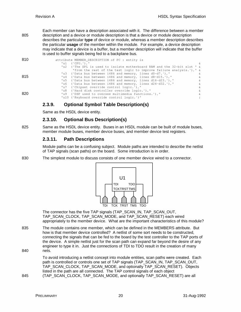
The simplest module to discuss consists of one member device wired to a connector.830
U1TDI TDOTCK TMS
TDI TDOTCK TMS
TRST
TRST
The connector has the five TAP signals (TAP_SCAN_IN, TAP_SCAN_OUT,TAP_SCAN_CLOCK, TAP_SCAN_MODE, and TAP_SCAN_RESET) each wiredappropriately to the member device. What are the important characteristics of this module?
The module contains one member, which can be defined in the MEMBERS attribute. But835how is that member device controlled? A netlist of some sort needs to be constructed,connecting the signals that can be fed to the board by the test controller to the TAP ports ofthe device. A simple netlist just for the scan path can expand far beyond the desire of anyengineer to type it in. Just the connections of TDI to TDO result in the creation of manynets.840
To avoid introducing a netlist concept into module entities, scan paths were created. Eachpath is controlled or controls one set of TAP signals (TAP_SCAN_IN, TAP_SCAN_OUT,TAP_SCAN_CLOCK, TAP_SCAN_MODE, and optionally TAP_SCAN_RESET). Objectslisted in the path are all connected. The TAP control signals of each object(TAP_SCAN_CLOCK, TAP_SCAN_MODE, and optionally TAP_SCAN_RESET) are all845
Revision A HSDL Syntax Specification
PRELIMINARY 21 31-Aug-1992
wired together. The TAP_SCAN_IN of each object is wired to the TAP_SCAN_OUT of thenext object.
To represent the simple board described earlier using this scheme, all that is required is toindicate that the connector and the device are in the same scan path, and that the connectorhas certain scan ports on it.850
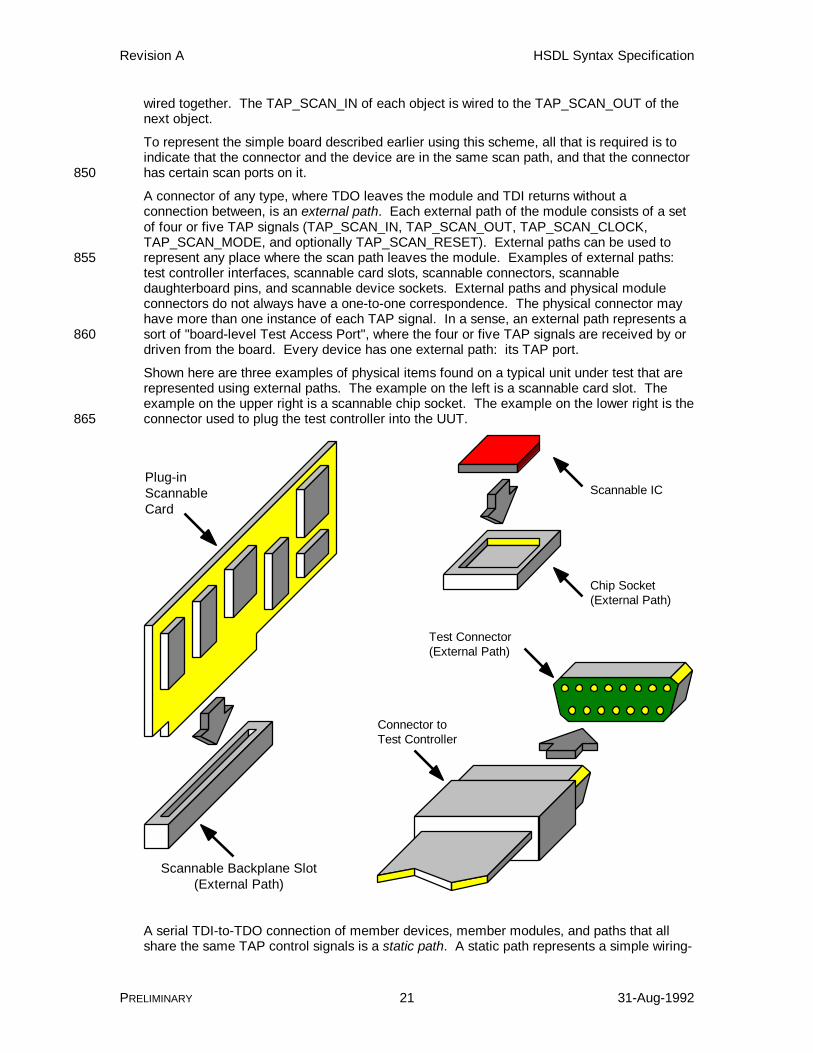
A connector of any type, where TDO leaves the module and TDI returns without aconnection between, is an external path. Each external path of the module consists of a setof four or five TAP signals (TAP_SCAN_IN, TAP_SCAN_OUT, TAP_SCAN_CLOCK,TAP_SCAN_MODE, and optionally TAP_SCAN_RESET). External paths can be used torepresent any place where the scan path leaves the module. Examples of external paths:855test controller interfaces, scannable card slots, scannable connectors, scannabledaughterboard pins, and scannable device sockets. External paths and physical moduleconnectors do not always have a one-to-one correspondence. The physical connector mayhave more than one instance of each TAP signal. In a sense, an external path represents asort of "board-level Test Access Port", where the four or five TAP signals are received by or860driven from the board. Every device has one external path: its TAP port.
Shown here are three examples of physical items found on a typical unit under test that arerepresented using external paths. The example on the left is a scannable card slot. Theexample on the upper right is a scannable chip socket. The example on the lower right is theconnector used to plug the test controller into the UUT.865
Plug-inScannableCard
(External Path)Scannable Backplane Slot
Test Controller
Test Connector(External Path)
Connector to
Scannable IC
Chip Socket(External Path)
A serial TDI-to-TDO connection of member devices, member modules, and paths that allshare the same TAP control signals is a static path. A static path represents a simple wiring-
Revision A HSDL Syntax Specification
PRELIMINARY 22 31-Aug-1992
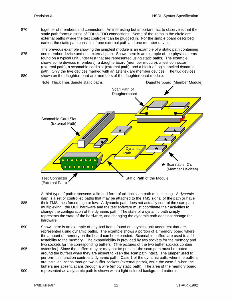
together of members and connectors. An interesting but important fact to observe is that the870static path forms a circle of TDI-to-TDO connections. Some of the items in the circle areexternal paths where the test controller can be plugged in. For the simple board describedearlier, the static path consists of one external path and one member device.
The previous example showing the simplest module is an example of a static path containingone member device and one external path. Shown here is an example of the physical items875found on a typical unit under test that are represented using static paths. The exampleshows some devices (members), a daughterboard (member module), a test connector(external path), a scannable card slot (external path), and a block of logic labelled dynamicpath. Only the five devices marked with an asterisk are member devices. The two devicesshown on the daughterboard are members of the daughterboard module.880
(External Path)Scannable Card Slot
Test Connector(External Path)
Daughterboard (Member Module)
Scan Path ofDaughterboard
DynamicPath
Scannable IC's(Member Devices)
*
**
**
*
Static Path of the Module
Note: Thick lines denote static paths.
A third type of path represents a limited form of ad-hoc scan path multiplexing. A dynamicpath is a set of controlled paths that may be attached to the TMS signal of the path or havetheir TMS lines forced high or low. A dynamic path does not actually control the scan path885multiplexing; the UUT hardware and the test software must coordinate their activities tochange the configuration of the dynamic path. The state of a dynamic path simplyrepresents the state of the hardware, and changing the dynamic path does not change thehardware.
Shown here is an example of physical items found on a typical unit under test that are890represented using dynamic paths. The example shows a portion of a memory board wherethe amount of memory on the board can be expanded. Scannable buffers are used to addtestability to the memory. The expandability is provided by two sockets for the memory andtwo sockets for the corresponding buffers. (The pictures of the two buffer sockets containasterisks.) Since the buffers may or may not be present, the scan path must be routed895around the buffers when they are absent to keep the scan path intact. The jumper used toperform this function controls a dynamic path. Case 1 of the dynamic path, when the buffersare installed, scans through two buffer sockets (external paths), while the case 2, when thebuffers are absent, scans through a wire (empty static path). The area of the memory boardrepresented as a dynamic path is shown with a light-colored background pattern.900

Revision A HSDL Syntax Specification
PRELIMINARY 23 31-Aug-1992
Scannable Buffer IC (Member Device)
Memory IC
Socket for AdditionalMemory IC
Jumper for AlteringScan Path(Dynamic Path)
Socket for Additional Scannable Buffer IC (External Path)
Scan Path for Memory Module (Static Path)
*
*
*
Case 1 (Buffers)
Case 2 (Wire)
= Dynamic Path
Using these three types of paths, how is the netlist of TAP signals represented? Each pathconsists of a set of four or five TAP signals. When an external path is defined, a set of fouror five TAP ports of the module must be associated with the external path. These portsrepresent physical pins on the module connector. When a static path is defined, at least one905external path is (eventually) included in the static path. This implicitly connects the TAPsignals of the scan path to the TAP ports of the external path. Static paths or dynamic pathsthat do not have an external path in them must be included inside another static path ordynamic path, and eventually all paths of any type are tied in to a master static path for themodule that does have external paths. In this way, all TDI-to-TDO nets are identified, and all910TMS signals, all TCK signals , and all optional TRST signals of the external paths are tiedtogether to form three nets (one for TMS, one for TCK, and one for TRST).
Another way of thinking about paths is that each item in a module has its own TAP. For anexternal path, the TAP is defined by the ports attached to the external path. Static anddynamic paths have a TAP. Devices have TAPs, and member modules (by virtue of their915external paths) also have TAPs. Listing an item in a path connects the TAP of the path tothe TAP of the item, building a netlist.
In the simple case described earlier (a board with one device and one test connector), manysimplifications can be made. An external path is not needed to describe this board, becauseonly one set of TAP signals exists for the board. Thus, only one path statement is needed, a920static path listing the single device on the board. The connection of the TAP signals to thestatic path and the creation of an external path for the board are all implied and do not needto be stated explicitly in this case.
External paths, static paths, and dynamic paths form a hierarchy of paths. The lowest-levelsubpaths are defined first and later included in the definitions of higher-level paths, until at925last the primary scan paths of the module are defined, incorporating all lower-level paths.

Revision A HSDL Syntax Specification
PRELIMINARY 24 31-Aug-1992
The example module HSDL entities shown later in this document should make the netlistand path concepts clearer.
Another statement related to external paths, the member connection, is used to attachmembers or paths to the external paths of a member module or device. For example, a930backplane module has several external paths. When that backplane module is included as amember in a higher-level, system module, the system module must plug items into theexternal paths of the backplane member. All the external paths of the backplane exceptone must have something plugged in to them. The one remaining external path is where thebackplane module is connected to the system module, usually in a static path.935
The declarations for external paths, static paths, and dynamic paths may be listed in anyorder necessary to describe the module. Modules may be built containing more than oneprimary scan path. If any members contain unresolved external paths, the memberconnections must be listed following all path declarations.
An example of a module that cannot be described using HSDL is shown here.940
U1 U2
TDI TDO
TCK1 TMS1 TCK2 TMS2
In this module, the connection of devices does not correspond to the HSDL definition of ascan path; that is, serially connected members or paths sharing the same set of TAPcontrol signals. These devices are serially connected, but they are connected to differentTAP_SCAN_CLOCK and TAP_SCAN_MODE ports.945
2.3.12. Optional External Path Declaration(s)External paths usually represent external connectors that contain a set of TAP signals, oneeach of TAP_SCAN_IN, TAP_SCAN_OUT, TAP_SCAN_CLOCK, TAP_SCAN_MODE, andoptionally TAP_SCAN_RESET ports. An external path is given a name so that it can bereferenced by other path declarations.950

Revision A HSDL Syntax Specification
PRELIMINARY 25 31-Aug-1992
External paths are declared with a constant, and list the TAP ports associated with theexternal path.
port (LCLK : inout bit; UUTCLK : out bit;955 TMSR : in bit; GND : linkage bit_vector (1 to 7); EVT0 : linkage bit; TDI : in bit; TDO : out bit;960 TMS, TRST : inout bit;
-- ram32 slot connectors J2_TCK, J2_TMS : inout bit; J2_TDI : out bit;965 J2_TDO : in bit; J2_DATABUS : inout bit_vector (31 downto 0); J2_ADDRBUS : out bit_vector (23 downto 0); J2_RW : out bit;
.970
.
.-- Scan Port Identificationattribute TAP_SCAN_IN of TDI : signal is true;attribute TAP_SCAN_MODE of TMS : signal is true;975attribute TAP_SCAN_OUT of TDO : signal is true;attribute TAP_SCAN_RESET of TRST : signal is true;attribute TAP_SCAN_CLOCK of LCLK : signal is (20.0e6, BOTH);
attribute TAP_SCAN_IN of J2_TDO : signal is true;980attribute TAP_SCAN_MODE of J2_TMS : signal is true;attribute TAP_SCAN_OUT of J2_TDI : signal is true;attribute TAP_SCAN_CLOCK of J2_TCK : signal is (20.0e6, BOTH);
.
.985
.constant J1 : EXTERNAL_PATH := "TDI, TDO, TMS, LCLK, TRST";constant J2 : EXTERNAL_PATH := "J2_TDI, J2_TDO, J2_TMS, J2_TCK";
In the example above, two external paths are shown. Both external paths use ports that aredefined such that either a test controller or a scannable module or device could be plugged990into them.
Note that if a board contains only one set of TAP signals, no external path need be defined.Its existence can be assumed.
A module must contain at least one external path where the TAP_SCAN_CLOCK,TAP_SCAN_MODE, and optional TAP_SCAN_RESET ports are either in or inout.995Otherwise, no test connector would exist on the module for plugging in the test controller.
An optional PATH_DESCRIPTION statement can be given for each external path. Thepurpose and function of the external path should be described in sufficient detail so that theoperator can understand what the external path represents.
attribute PATH_DESCRIPTION of J1 : constant is1000 "J1 is the scan test connector for this board.";
2.3.13. Static Path Declaration(s)Static paths define known, fixed, serially-connected member devices, member modules, orother paths. The items listed in the static path are connected serially, with the TDO of oneitem connected to the TDI of the item on its right. The TAP control signals1005(TAP_SCAN_CLOCK, TAP_SCAN_MODE, and optional TAP_SCAN_RESET) of all itemslisted are interconnected: all clocks on one net, all mode selects on another net, and allresets on a third net.
Revision A HSDL Syntax Specification
PRELIMINARY 26 31-Aug-1992
constant subpath1 : STATIC_PATH := "u3, u4, u5, u6";constant short : STATIC_PATH := "";1010 -- subpath2 is equivalent to "u19, u3, u4, u5, u6, u18"constant subpath2 : STATIC_PATH := "u19, subpath1, u18";constant boardpath : STATIC_PATH := "J1, u1, u2, u7, J3, J4, J5, u8, dpath, u10";
The examples above show three static paths. Subpath1 is a simple static path consisting offour serially connected devices. Short is an empty static path, which simply shorts TDI to1015TDO. A short can be useful for "closing" external paths and for creating emptyconfigurations of a dynamic path. Boardpath is a static path containing devices (beginningwith "u"), external paths (beginning with "J"), and a dynamic path (beginning with "d").
Static paths are "circular" in the sense that the TDI of the first item in the static path isimplicitly connected to the TDO of the last item in the static path. When a static path is1020listed as an item in a new path, the TDI of the first item in the first static path is connected tothe TDO of the preceding item in the new path, and the TDO of the last item in the first staticpath is connected to the TDI of the following item in the new path. Conceptually, each staticpath has a TAP, and when one is listed in another, their TAPs are connected.
In the example shown here, boardpath is intended to be the primary scan path of the1025module. The presence of external paths in this static path is a clue. If boardpath is notincluded in any other path, it is (one of) the primary scan path(s) of the module.
An optional PATH_DESCRIPTION statement can be given for each static path. Thepurpose and function of the static path should be described in sufficient detail so that theoperator can understand what portion of the unit under test is covered by the static path.1030
attribute PATH_DESCRIPTION of short : constant is "Short is an empty static path, representing a wire between TDI and TDO.";
2.3.14. Optional Dynamic Path Declaration(s)A dynamic path describes a limited form of ad-hoc scan path multiplexing. A fixed set ofitems (paths or members) may be multiplexed. A dynamic path has one or more1035configurations, where each configuration selects one of the items from the set to be placedin the scan path (connected to the TAP_SCAN_MODE signal), and the other items are eitherin Test-Logic-Reset or Run-Test/Idle state.
constant dpath : DYNAMIC_PATH := "0 (u9:dpath, short:1 )," &1040 "1 (u9:1, short:dpath) " ;
In this example, the dynamic path named dpath has two different configurations, or dynamicpath cases. Each configuration indicates that one of the two items is connected to the TMSsignal of the scan path and the other item is placed in Test-Logic-Reset. Case 0 connectsthe TAP_SCAN_MODE signal of member device u9 to the TAP_SCAN_MODE signal of the1045dynamic path, and the TAP_SCAN_MODE signal of the static path short to a fixed high (1),forcing it to Test-Logic-Reset. Case 1 connects the u9's TAP_SCAN_MODE signal to afixed high (1) and short's TAP_SCAN_MODE signal to the dynamic path'sTAP_SCAN_MODE signal.
Items in a dynamic path case that are not connected to TMS are assumed to be built so that1050their TDI/TDO ports are multiplexed out of the serial TDI-to-TDO chain, so that shiftingoperations do not involve them.
It is undefined whether the operation of multiplexing an item out of the dynamic path stopsthe test clock for that item or allows it to continue running. HSDL translators must assumethat the test clock is stopped (this is the worst-case assumption). It is also undefined1055whether an item is placed in Test-Logic-Reset by manipulating its TAP controller state(pulling TMS high and clocking TCK five cycles) or by pulling TRST low. In other words, theactions of the item described by the dynamic path may not exactly describe what thehardware is doing. The only requirement is that the condition of the test controller's software

Revision A HSDL Syntax Specification
PRELIMINARY 27 31-Aug-1992
model of the item described by the dynamic path matches the condition of the hardware1060when it is multiplexed back into the scan path.
An optional PATH_DESCRIPTION statement can be given for each dynamic path. Thepurpose and function of the dynamic path should be described in sufficient detail so that theoperator can understand what the dynamic path models and what it is used for.
attribute PATH_DESCRIPTION of dpath : constant is1065 "The dynamic path dpath is used to remove the C40 from " & "the scan path if the device is not mounted on the board.";
2.3.15. Optional Member ConnectionsA requirement of HSDL is that all external paths of a member be connected to something,except the one external path that is used to control the member. What does this1070requirement mean, and why is there one exception?
Consider a backplane module intended for incorporation into a computer module. Thebackplane has one test connector (an external path) and multiple card slots (also externalpaths). The computer module declares the backplane module as a member. To plug thebackplane module into one of the scan paths of the computer module, HSDL must know1075which one to use. How can this be determined? One of the external paths of the backplanemember is listed in a static path or dynamic path, and the other external paths must havesomething plugged into them with the CONNECTIONS attribute.
A secondary reason for forcing all external paths to have something plugged in to them isthat the test controller will only have to check the highest-level entity of the UUT for1080unresolved external paths when the UUT's entity is loaded by the test controller. If the useraccidentally forgot to plug something into an external path five levels deep in the hierarchy,it could be weeks before the error is caught. To improve error detection in HSDL, allmembers with external paths must have those external paths resolved.
Sometimes it is desirable to leave external paths empty so that something may be plugged1085into them in a higher-level entity. To do this, a new external path is defined in the currententity and plugged in to the member's external path. This extra effort may be tedious butcan avoid many errors and much complication of the test controller.
To plug items into member external paths, the CONNECTIONS attribute is used. TheCONNECTIONS attribute must appear following all path declarations only if any member1090devices or member modules contain unresolved external paths.
attribute CONNECTIONS of fiction : entity is "u2 (ssp1:subpath1, ssp2:j2, ssp3:*, ssp4:*)";
In this example, the member named u2 has five external paths (remember that one of theseexternal paths is not shown). Member u2's external path ssp1 has a static path named1095subpath1 attached to it. Member external path ssp2 has another external path connected toit named j2. External paths ssp3 and ssp4 are permanently not connected to anything(permanently open).
Normally this is illegal (it creates a permanent open in the scan path), but u2 happens to be aTI Scan Path Linker, SN74ACT8997. This device has four external paths that are under the1100control of dynamic paths, and these external paths can be multiplexed out of the scan path.Leaving the external paths permanently open implies that the test controller must forbid theoperator from using certain configurations of the dynamic paths in the device.
2.3.16. Path RequirementsThis section defines the rules that must be followed when combining EXTERNAL_PATH1105constants, STATIC_PATH constants, DYNAMIC_PATH constants, and the CONNECTIONSattribute to completely describe all scan paths of the unit under test.

Revision A HSDL Syntax Specification
PRELIMINARY 28 31-Aug-1992
A primary scan path represents a complete TDI-to-TDO connection from a TDI input of themodule to a TDO output of the module. It includes all member devices, member modules,external paths, static paths, and dynamic paths that make up the primary scan path. All1110modules have at least one primary scan path, but may have more. The ultimate purpose ofdefining external, static and dynamic paths is to define the primary scan paths of themodule.
Primary Path of the Module
Module Containing One Primary Path
Another Primary Path of the Module
Module Containing Two Primary PathsOne Primary Pathof the Module
1115A test connector is an external path whose TAP_SCAN_CLOCK, TAP_SCAN_MODE, and, ifpresent, TAP_SCAN_RESET ports all have mode IN or mode INOUT. Such an externalpath may be controlled by a test controller. A unit-under-test connector is an external pathwhose TAP_SCAN_CLOCK, TAP_SCAN_MODE, and, if present, TAP_SCAN_RESET portsall have mode INOUT or mode OUT. Such an external path may drive a unit-under-test.1120Every module must define at least one test connector. An external path whoseTAP_SCAN_CLOCK, TAP_SCAN_MODE, and, if present, TAP_SCAN_RESET ports allhave mode IN is a pure test connector, all have mode INOUT may be a test connector or aunit-under-test connector, or all have mode OUT is a pure unit-under-test connector. Theselected test connector is the test connector that the test controller is connected to for the1125duration of the test.
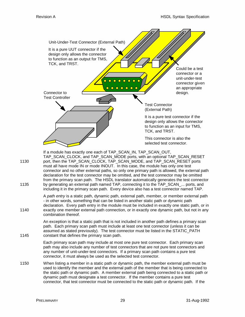
Revision A HSDL Syntax Specification
PRELIMINARY 29 31-Aug-1992
Unit-Under-Test Connector (External Path)
Test Connector(External Path)
Could be a testconnector or aunit-under-testconnector givenan appropriatedesign.
Test ControllerConnector to
This connector is also theselected test connector.
It is a pure test connector if thedesign only allows the connectorto function as an input for TMS,TCK, and TRST.
It is a pure UUT connector if thedesign only allows the connectorto function as an output for TMS,TCK, and TRST.
If a module has exactly one each of TAP_SCAN_IN, TAP_SCAN_OUT,TAP_SCAN_CLOCK, and TAP_SCAN_MODE ports, with an optional TAP_SCAN_RESETport, then the TAP_SCAN_CLOCK, TAP_SCAN_MODE, and TAP_SCAN_RESET ports1130must all have mode IN or mode INOUT. In this case, the module has only one testconnector and no other external paths, so only one primary path is allowed, the external pathdeclaration for the test connector may be omitted, and the test connector may be omittedfrom the primary scan path. The HSDL translator automatically generates the test connectorby generating an external path named TAP, connecting it to the TAP_SCAN_... ports, and1135including it in the primary scan path. Every device also has a test connector named TAP.
A path entry is a static path, dynamic path, external path, member, or member external path- in other words, something that can be listed in another static path or dynamic pathdeclaration. Every path entry in the module must be included in exactly one static path, or inexactly one member external path connection, or in exactly one dynamic path, but not in any1140combination thereof.
An exception is that a static path that is not included in another path defines a primary scanpath. Each primary scan path must include at least one test connector (unless it can beassumed as stated previously). The test connector must be listed in the STATIC_PATHconstant that defines the primary scan path.1145
Each primary scan path may include at most one pure test connector. Each primary scanpath may also include any number of test connectors that are not pure test connectors andany number of unit-under-test connectors. If a primary scan path contains a pure testconnector, it must always be used as the selected test connector.
When listing a member in a static path or dynamic path, the member external path must be1150used to identify the member and the external path of the member that is being connected tothe static path or dynamic path. A member external path being connected to a static path ordynamic path must designate a test connector. If the member contains a pure testconnector, that test connector must be connected to the static path or dynamic path. If the

Revision A HSDL Syntax Specification
PRELIMINARY 30 31-Aug-1992
member has only one test connector, the member name alone may be used, and the1155member test connector is implicitly connected to the static path or dynamic path.
Each external path of a member is connected to one of the primary scan paths of themember. More than one of these may be test connectors, but only one may be a pure testconnector. Exactly one external path per primary scan path of a member may be connectedto a static path or dynamic path. If two could be connected, a subpath would be created that1160could not be controlled by a test controller.
All external paths of each member must be connected to a path entry. When a member hasmore than one external path, the CONNECTIONS attribute must be used to connect themember external paths that were not included in a static path or dynamic path. If used, theCONNECTIONS attribute must follow all EXTERNAL_PATH, STATIC_PATH, and1165DYNAMIC_PATH constants.
The maximum operating frequencies for all TAP_SCAN_CLOCK ports that are part of theexternal paths in a primary path must be the same. The frequencies may be different forexternal paths in different primary paths. The port's TAP_SCAN_CLOCK frequency isinterpreted as the maximum operating frequency of the primary path.1170
2.3.17. Optional Constraint Description(s)Same as the HSDL device entity.
2.3.18. Optional Design WarningUnchanged from BSDL. The DESIGN_WARNING attribute is not discussed in the BSDLSyntax chapter of the HP Boundary-Scan Tutorial and BSDL Reference Guide, but is1175described in the Introduction to BSDL chapter under the section Miscellaneous Declarations.This statement is optional.
Revision A HSDL Syntax Specification
PRELIMINARY 31 31-Aug-1992
3. Using HSDL
This section describes how HSDL can be used to solve selected scan description problems.Many HSDL statements are covered informally during the discussion.1180
3.1. Describing Architectures Above the Device LevelIn HSDL, any level of scan architecture above the device level is called a module. To describe amodule, an HSDL module entity is created. Module entities begin just like device entities butdiffer substantially after the use statements.
Begin the module with an entity statement, a generic statement, a port statement listing all the1185module pins, and a use STD_1149_1_1990.all statement. This part of the module description isexactly like the corresponding parts of the device description. Note that in a module, many morepins (called ports in HSDL) may need to be listed depending on the complexity of the module.
entity gdm is -- Generic Parameter1190 generic (PHYSICAL_PIN_MAP : string := "UNDEFINED");
-- Logical Port Description port (LCLK : in bit; UUTCLK : out bit;1195 TMSR : in bit; GND : linkage bit_vector (1 to 7); EVT0 : linkage bit; TDO : out bit; TMS, TDI, TRST : in bit);1200
-- Use Statement use STD_1149_1_1990.all; -- Get Std 1149.1-1990 attributes and definitions
Module entities contain the use HSDL_module.all statement after the statement useSTD_1149_1_1990.all to indicate that a module is being described. These are the only use1205statements that are needed, and the only two that are allowed, in a module entity.
use HSDL_module.all; -- Get HSDL extensions for modules
After the two use statements, define the different packages for the module. Most modules onlyhave one package type. Define the packages using the PIN_MAP attribute followed byPIN_MAP_STRING constants, one for each package. Pin numbering can use identifiers like1210J1_2 as well as numbers like 5. Identifiers are more common for boards that contain severalslots, sockets, connectors, etc.
-- Package Pin Mapping attribute PIN_MAP of gdm : entity is PHYSICAL_PIN_MAP; constant ONLY_PACKAGE : PIN_MAP_STRING :=1215 "LCLK: 1, UUTCLK: 2, TDI: 3, TDO: 4, TMS: 5, TMSR: 6, TRST: 7," & "EVT0: 8, GND: (9, 10, 11, 12, 13, 14, 15)";
Scan port identification appears next. Include the attributes TAP_SCAN_IN, TAP_SCAN_OUT,TAP_SCAN_CLOCK, TAP_SCAN_MODE, and TAP_SCAN_RESET (if the module has anyTRST signals) for each 1149.1 signal on the module that can be accessed from a port on the1220module. Again, most modules only have one TAP, so only one each of the TAP_SCAN_...attributes is needed.
-- Scan Port Identification attribute TAP_SCAN_IN of TDI : signal is true; attribute TAP_SCAN_MODE of TMS : signal is true;1225 attribute TAP_SCAN_OUT of TDO : signal is true; attribute TAP_SCAN_RESET of TRST : signal is true; attribute TAP_SCAN_CLOCK of LCLK : signal is (20.0e6, BOTH);
At this point the module entity begins to look quite different from the device entity. Statementsin the device entity that described the instruction register, idcode and usercode registers,1230instructions, user-defined test registers, and the boundary are not needed and make no sense for
Revision A HSDL Syntax Specification
PRELIMINARY 32 31-Aug-1992
a module entity. In their place, new statements describe the devices and modules contained inthis module and the order of these devices and modules in the scan path.
Include the MEMBERS attribute to list each of the devices and modules that are contained in themodule being described. Many modules contain only devices. Assign a different name to each1235member, using the reference designator from the schematic as the name to avoid confusion.The entity and package used for each member must also be defined. Look in the entity file foreach device and module used to decide which package pinout is used on the hardware and listthat package name in the MEMBERS attribute.
-- Member Description1240 attribute MEMBERS of gdm : entity is "u19 (ttl74bct8244, NT_PACKAGE)," & "u21 (ttl74bct8244, NT_PACKAGE)," & "u9 (ttl74bct8244, NT_PACKAGE)," & "u8 (ttl74bct8244, NT_PACKAGE)," &1245 "u1 (ttl74bct8244, NT_PACKAGE)," & "u22 (ttl74bct8373, NT_PACKAGE)," & "u20 (cf93279, FK_PACKAGE)";
Finally, describe the scan paths of the module. Most modules contain only a simple serial scanpath that can be described with one STATIC_PATH constant. List the members in the1250STATIC_PATH constant in the order they appear on the module, listing the member closest toTDI first and the member closest to TDO last.
-- Paths of the module constant path1 : STATIC_PATH := "u22, u1, u8, u19, u21, u20, u9";
The last statement of the module is the end entity statement, completing the description.1255end gdm;
Only ten different types of statements are needed to describe a simple module, as shown here:entity, generic, port, use, PIN_MAP attribute, PIN_MAP_STRING constants, TAP_SCAN_...attributes, MEMBERS attribute, STATIC_PATH constant, and end.
3.2. Describing a Board, Box, Subsystem, or System1260
The method for describing a module is used to describe any board, box, subsystem, or system.As the module being described gets higher in the hierarchy of the unit under test, fewer membersof the module are devices and more members are modules. This does not involve any newconcepts - HSDL module descriptions treat a module and a device in the same way. Both aremembers.1265
Complex boards, especially backplanes used in more complex systems, may contain scannablecard slots, chip sockets, card edge connectors, and even more than one test connector forplugging in the test controller. Describe these hardware constructs, which each involve an openin the scan path that is resolved later, using external paths. See Describing a Backplane fordetails.1270
Some boards may be designed with scannable devices that may or may not be installed. Thescan path around the scannable devices may be jumpered to skip around them. Later, when theboard is upgraded, the scan path is rejumpered to include the devices. This is an example of ad-hoc scan path multiplexing. Other such ad-hoc methods are possible, such as using a scannablebuffer and a multiplexer to enable and disable secondary scan paths. Boards and other modules1275that use ad-hoc methods are described using dynamic paths. See Controlling Ad-Hoc Scan PathMultiplexing for details.
Module-level designs often include new buses and signals that are not directly related to thenames of the signals provided by devices. For example, four different eight-bit buffers may beused to drive a data bus. A natural desire is to want to use the name of the data bus to perform1280testing, not the names of each of the device pins. In HSDL, bus names can be assigned to anycombination of member signals. See Assigning a Name to a Bus on a Board for details.

Revision A HSDL Syntax Specification
PRELIMINARY 33 31-Aug-1992
Boards often have design constraints that disallow certain hazardous conditions from beingestablished. The constraints prevent damage to the board. During testing, these designconstraints may be overridden by test-mode instructions. Constraint expressions can be used to1285prevent damage from occurring, even when a test-mode instruction is in effect. See PreventingIllegal Hardware Conditions for details.
3.3. Describing a Multichip ModuleIn HSDL, multichip modules (MCMs) are conceptually no different from a regular board, and aredescribed using the same set of statements. See Describing a Board, Box, Subsystem, or1290System for details.
3.4. Describing a BackplaneComplex boards, especially backplanes used in more complex systems, may contain scannablecard slots, chip sockets, card edge connectors, and even more than one test connector forplugging in the test controller. Describe these hardware constructs, which each involve an open1295in the scan path that is resolved later, using external paths.
Define an external path using the EXTERNAL_PATH constant. Each external path has a TAPassociated with it, consisting of a set of four test signals (or five, if TRST is present). Define theTAP for an external path by listing the names of each test signal in the string following theEXTERNAL_PATH.1300
constant j1 : EXTERNAL_PATH := "TDI, TDO, TMS, TCK, TRST";
An external path is used to describe each slot, socket, connector, and so on that contains testsignals going off or coming onto the module. External paths are classified three ways,depending on whether the test signals are input only, output only, or input/output. The TDI signalis always an input and the TDO signal is always an output.1305
A card slot or chip socket that a scannable board or device can be plugged into is normallydesigned so that its TMS, TCK, and TRST signals are all outputs. In HSDL terminology, this is aunit-under-test connector. The EXTERNAL_PATH names four or five ports that are listed inTAP_SCAN_... attributes. Define the ports named by TAP_SCAN_MODE, TAP_SCAN_CLOCK,and TAP_SCAN_RESET as out ports in the port statement.1310
port (TDI : in bit; TDO : out bit; TMS, TCK, TRST : out bit); -- all outputs
. .1315 .
constant slot1 : EXTERNAL_PATH := "TDI, TDO, TMS, TCK, TRST";
A connector that the test controller can be plugged into is normally designed so that its TMS,TCK, and TRST signals are all inputs. In HSDL terminology, this is a test connector. TheEXTERNAL_PATH names four or five ports that are listed in TAP_SCAN_... attributes. Define1320the ports named by TAP_SCAN_MODE, TAP_SCAN_CLOCK, and TAP_SCAN_RESET as inports in the port statement.
port (TDI : in bit; TDO : out bit; TMS, TCK, TRST : in bit); -- all inputs1325 . . .
constant test : EXTERNAL_PATH := "TDI, TDO, TMS, TCK, TRST";
It is possible, although unlikely, that a card slot may be designed so that either a scannable card,1330which receives TAP signals, or a test controller, which drives TAP signals, could be plugged intoit. A backplane of such slots would not require a dedicated test connector, although the designwould probably be expensive in terms of real estate, speed, and so on. To describe such a slot,
Revision A HSDL Syntax Specification
PRELIMINARY 34 31-Aug-1992
define the ports named by TAP_SCAN_MODE, TAP_SCAN_CLOCK, and TAP_SCAN_RESETas inout ports in the port statement.1335
port (TDI : in bit; TDO : out bit; TMS, TCK, TRST : inout bit); -- all inouts
. .1340 .
constant test : EXTERNAL_PATH := "TDI, TDO, TMS, TCK, TRST";
The primary scan path for a backplane is still described using a STATIC_PATH constant. Thetest connector must be listed in the static path, and by convention it is listed first. Then list theexternal path names, which define the slots, sockets, and so forth, and the member devices on1345the backplane in the order they appear. List the item closest to TDI right after the name of thetest connector, and the item closest to TDO last.
constant primary : STATIC_PATH := "j1, slot1, slot2, slot3, u1";
3.5. Assigning a Name to a Subset of a Test RegisterTest register names and contents are not usually the most convenient way to examine the data1350shifted into and out of a device. The instruction register and bypass register contain only oneitem of information, the instruction opcode and bypass bit, respectively. But many other testregisters, including the identification register and the boundary register, are broken up intonamed subsets.
The identification register contains four subsets: a fixed '1' bit in the LSB, an 11-bit manufacturer1355identity field, a 16-bit part number field, and a 4-bit version field. The boundary potentiallycontains dozens of different fields, each corresponding to a grouping of cells connected torelated device pins. For example, all output cells connected to a 32-bit data bus might need tobe controlled or observed.
User-defined instructions and test registers, in order to reduce the overhead needed to1360implement testability features, often place many items of information in the same test register, ormay even use a single test register in the hardware to load many kinds of information dependingon the instruction used to shift through that register.
Define buses in the device entity, using the BUS_COMPOSITION attribute, to assign names toeach of these test register subsets. Usually a bus consists of adjacent bits from one test register,1365making description easy. List the bus name and length, followed by the test register name andbit numbers giving the MSB and LSB of the bus. Remember from 1149.1 that bit 0 is the LSBand is closest to TDO. By reversing the MSB and LSB, the bit ordering in the bus can be theinverse of the bit order in the test register.
attribute BUS_COMPOSITION of My_IC : entity is1370 "version[4] (IDCODE[31,28])," & "part_number[16] (IDCODE[27,12])," & "manufacturer[11] (IDCODE[11, 1])";
attribute BUS_COMPOSITION of ttl74bct8374 : entity is "inputs[8] (BOUNDARY[ 8,15])," &1375 "outputs[8] (BOUNDARY[ 0, 7])," & "aux[2] (BOUNDARY[16,17])," & "lfsr[16] (BOUNDARY[ 0,15])";
Buses can contain any number of cells in any order from any number of test registers or evenbuses. In cases where the hardware design has been heavily optimized the bits may be1380scattered throughout a test register in any order. In rare instances related bits of informationmay be located in different test registers. A bus can describe all these cases by using a list ofbus components.
Revision A HSDL Syntax Specification
PRELIMINARY 35 31-Aug-1992
attribute BUS_COMPOSITION of My_FPGA : entity is "databus_inputs[32] (BOUNDARY[ 0], BOUNDARY[ 3], BOUNDARY[ 6], BOUNDARY[ 9]," &1385 "BOUNDARY[12], BOUNDARY[15], BOUNDARY[18], BOUNDARY[21]," & "BOUNDARY[24], BOUNDARY[27], BOUNDARY[30], BOUNDARY[33]," & "BOUNDARY[36], BOUNDARY[39], BOUNDARY[42], BOUNDARY[45]," & "BOUNDARY[48], BOUNDARY[51], BOUNDARY[54], BOUNDARY[57]," & "BOUNDARY[60], BOUNDARY[63], BOUNDARY[66], BOUNDARY[69]," &1390 "BOUNDARY[72], BOUNDARY[75], BOUNDARY[78], BOUNDARY[81]," & "BOUNDARY[84], BOUNDARY[87], BOUNDARY[90], BOUNDARY[93] " ;
3.6. Assigning a Name to a Bus on a BoardModule-level designs often include new buses and signals that are not directly related to thenames of the signals provided by devices. For example, four different eight-bit buffers may be1395used to drive a data bus. A natural desire is to want to use the name of the data bus to performtesting, not the names of each of the device pins. In HSDL, bus names can be assigned to anycombination of member signals.
Define buses in the module entity using the BUS_COMPOSITION attribute. A module-level busmay consist of a single bit from a single device, or multiple bits from several devices. List the1400bus name and length, followed by the test register name(s) and bit numbers giving the MSB andLSB of each component of the bus. Remember from 1149.1 that bit 0 is the LSB and is closestto TDO. By reversing the MSB and LSB, the bit ordering of a component can be the inverse ofthe bit order in the underlying test register.
attribute BUS_COMPOSITION of My_Board : entity is1405 "addrbus[32] (u1.output, u2.output, u3.output, u4.output)," & "databus[32] (u5.a, u6,a, u7.a, u8.a)";
3.7. Assigning a Symbolic Name to a ValueSome test registers and buses, like the instruction register, have commands, options, and soforth that have symbolic names. Often these names are listed on the device data sheet.1410
Define a symbol table of symbol names and values using the SYMBOL_TABLE attribute.constant BCR_Opcodes : SYMBOL_TABLE := "SAMTOG (00)," & "PRPG (01)," & "PSA (10)," &1415 "PSAPRPG (11)";
To associate the symbols with the test register or bus they belong to, use the attributesBOUNDARY_SYMBOLS, BUS_SYMBOLS, and REGISTER_SYMBOLS. See AssigningSymbolic Names to a Test Register or Bus for details.
3.8. Assigning Symbolic Names to a Test Register or Bus1420
Once a symbol table has been defined (see Assigning a Symbolic Name to a Value for details), itcan be attached to a test register, a bus, or a device port. The symbols in the table can then beused instead of bit patterns when specifying values to shift in. The symbols are also displayedinstead of bit patterns when examining values that were shifted out.
Use the REGISTER_SYMBOLS attribute to attach a symbol table to a test register.1425attribute REGISTER_SYMBOLS of ttl74bct8374 : entity is "BCR (BCR_Opcodes)";
Use the BUS_SYMBOLS attribute to attach a symbol table to a bus.attribute BUS_SYMBOLS of ttl74bct8374 : entity is "aux (AUX_SYMBOLS)";1430
Use the BOUNDARY_SYMBOLS attribute to attach a symbol table to a specific type of cellattached to a port. Each different cell function (input, clock, output2, output3, bidir, control,controlr, and internal) can have a different symbol table. Typically, the symbol table only makessense for clock cells, control cells, and input and output cells on single-bit ports.

Revision A HSDL Syntax Specification
PRELIMINARY 36 31-Aug-1992
attribute BOUNDARY_SYMBOLS of ttl74bct8374 : entity is1435 "CLK (input, clk_symbols)," & "OC_NEG (input, oc_symbols)";
3.9. Preventing Illegal Hardware ConditionsBoards often have design constraints that disallow certain hazardous conditions from beingestablished. The constraints prevent damage to the board. During testing, these design1440constraints may be overridden by test-mode instructions. Constraint expressions can be used toprevent damage from occurring, even when a test-mode instruction is in effect.
Define a constraint using the CONSTRAINTS attribute. Constraints can be defined for bothmodules and devices. Each constraint is given a name that can be displayed by the testcontroller when the constraint is violated. The constraint expression is a logical expression that,1445when true, indicates that a constraint has been violated. The constraints are evaluted beforeeach scan operation shifts data into the hardware, to ensure that the data is acceptable.Alternatively, ATPG software can use the constraints to prevent the creation of vectors thatwould otherwise damage the hardware.
3.10. Adding Descriptions to Each Item in the Entity1450
Reading a BSDL or HSDL description of a device or module is not the easiest undertaking. Thesyntax is too cluttered and the information too terse to be immediately understandable. Textualdescriptions can be added to HSDL device and module entities to overcome this.
Define a text description for both electronic documentation and help in interactive tools.Descriptions can be attached to buses (BUS_DESCRIPTION), constraints1455(CONSTRAINT_DESCRIPTION), device entity names (DEVICE_DESCRIPTION), instructionopcodes (INSTRUCTION_DESCRIPTION), member names (MEMBER_DESCRIPTION),module entity names (MODULE_DESCRIPTION), test register names(REGISTER_DESCRIPTION), symbol names (SYMBOL_DESCRIPTION), dynamic paths(PATH_DESCRIPTION), external paths (PATH_DESCRIPTION), and static paths1460(PATH_DESCRIPTION). These descriptions can be displayed by a tool when information isrequested by the user.
3.11. Controlling Ad-Hoc Scan Path MultiplexingSome boards may be designed with scannable devices that may or may not be installed. Thescan path around the scannable devices may be jumpered to skip around them. Later, when the1465board is upgraded, the scan path is rejumpered to include the devices. This is an example of ad-hoc scan path multiplexing. Other ad-hoc methods are possible, such as using a scannablebuffer and a multiplexer to enable and disable secondary scan paths. Boards and other modulesthat use ad-hoc methods are described using dynamic paths.
Define a dynamic path using the DYNAMIC_PATH attribute. Each case of the dynamic path lists1470all the possible items for all cases, and selects one for inclusion in the scan path. The others areeither in Test-Logic-Reset or Run-Test/Idle state.
constant dpath : DYNAMIC_PATH := "0 (u9:dpath, short:1 )," & "1 (u9:1, short:dpath)";1475
Each item selected by the dynamic path may need to be a list of one or more members, externalpaths, static paths, or even dynamic paths. Since the dynamic path only allows a single namefor each item, so additional static paths may need to be defined using STATIC_PATH constants.This restriction is intended to keep dynamic paths short and readable.
Revision A HSDL Syntax Specification
PRELIMINARY 37 31-Aug-1992
4.1480
Example HSDL Device Description
This example is an HSDL description for the Texas Instruments SN74BCT8374 Octal D-TypeFlip-Flop. It is based on the original BSDL description of the same device found in the HPBoundary-Scan Tutorial and BSDL Reference Manual.
Do not consider this to be the official HSDL description of the SN74BCT8374. It is only an1485example used to illustrate extensions in HSDL.
entity ttl74bct8374 is -- Generic Parameter generic (PHYSICAL_PIN_MAP : string := "UNDEFINED");1490
-- Logical Port Description port (CLK : in bit; Q : out bit_vector (1 to 8); D : in bit_vector (1 to 8);1495 GND, VCC : linkage bit; OC_NEG : in bit; TDO : out bit; TMS, TDI, TCK : in bit);
1500 -- Use Statement use STD_1149_1_1990.all; -- Get Std 1149.1-1990 attributes and definitions use HSDL_device.all; -- Get HSDL extensions for devices
attribute DEVICE_DESCRIPTION of ttl74bct8374 : entity is1505 "SN74BCT8374 is a Scan Test Devices with Octal D-Type Edge-Triggered " & "Flip-Flops. In normal mode, on the positive transition of CLK the Q " & "outputs take on the logic levels setup up at the D inputs. The " & "output enable OC_NEG is used to place the Q outputs in the " & "high-impedance state, but does not affect the internal operations " &1510 "of the flip-flop.";
-- Port Descriptions attribute PORT_DESCRIPTION of D : signal is "Eight-bit input bus of the device.";1515 attribute PORT_DESCRIPTION of Q : signal is "Eight-bit output bus of the device. All outputs can be set to " & "high-impedance by placing a 1 on the OC_NEG pin. All outputs can be " & "updated with the values on the input bus D on a positive transition " & "of CLK.";1520 attribute PORT_DESCRIPTION of CLK : signal is "Edge-triggered flip-flop clock control of the device. All pins on " & "the output bus Q can be updated with the values on the input bus D " & "on a positive transition of CLK."; attribute PORT_DESCRIPTION of OC_NEG : signal is1525 "Output control of the device. All pins on the output bus Q can be " & "set to high-impedance by placing a 1 on the OC_NEG pin. Disabling " & "the output bus Q has no effect on the internal operation of the " & "flip-flops.";
1530 -- Package Pin Mapping attribute PIN_MAP of ttl74bct8374 : entity is PHYSICAL_PIN_MAP; constant DW_PACKAGE : PIN_MAP_STRING := "CLK:1, Q:(2,3,4,5,7,8,9,10), D:(23,22,21,20,19,17,16,15)," & "GND:6, VCC:18, OC_NEG:24, TDO:11, TMS:12, TCK:13, TDI:14";1535 constant FK_PACKAGE : PIN_MAP_STRING := "CLK:9, Q:(10,11,12,13,16,17,18,19), D:(6,5,4,3,2,27,26,25)," & "GND:14, VCC:28, OC_NEG:7, TDO:20, TMS:21, TCK:23, TDI:24"; constant NT_PACKAGE : PIN_MAP_STRING := "CLK:1, Q:(2,3,4,5,7,8,9,10), D:(23,22,21,20,19,17,16,15)," &1540 "GND:6, VCC:18, OC_NEG:24, TDO:11, TMS:12, TCK:13, TDI:14";
-- Scan Port Identification attribute TAP_SCAN_IN of TDI : signal is true; attribute TAP_SCAN_MODE of TMS : signal is true;1545
Revision A HSDL Syntax Specification
PRELIMINARY 38 31-Aug-1992
attribute TAP_SCAN_OUT of TDO : signal is true; attribute TAP_SCAN_CLOCK of TCK : signal is (20.0e6, BOTH);
-- TAP Description attribute INSTRUCTION_LENGTH of ttl74bct8374 : entity is 8;1550 attribute INSTRUCTION_OPCODE of ttl74bct8374 : entity is "BYPASS (11111111, 10001000, 00000101, 10000100, 00000001)," & "EXTEST (00000000, 10000000)," & "SAMPLE (00000010, 10000010)," & "INTEST (00000011, 10000011)," &1555 "TRIBYP (00000110, 10000110)," & -- Boundary Hi-Z "SETBYP (00000111, 10000111)," & -- Boundary 1/0 "RUNT (00001001, 10001001)," & -- Boundary run test "READBN (00001010, 10001010)," & -- Boundary read normal "READBT (00001011, 10001011)," & -- Boundary read test1560 "CELLTST (00001100, 10001100)," & -- Boundary selftest normal "TOPHIP (00001101, 10001101)," & -- Boundary toggle out test "SCANCN (00001110, 10001110)," & -- BCR Scan normal "SCANCT (00001111, 10001111)"; -- BCR Scan test attribute INSTRUCTION_CAPTURE of ttl74bct8374 : entity is "10000001";1565 attribute INSTRUCTION_DISABLE of ttl74bct8374 : entity is "TRIBYP"; attribute INSTRUCTION_GUARD of ttl74bct8374 : entity is "SETBYP"; attribute INSTRUCTION_NORMAL of ttl74bct8374 : entity is "BYPASS, SAMPLE, READBN, CELLTST, SCANCN"; attribute INSTRUCTION_TEST of ttl74bct8374 : entity is1570 "EXTEST, INTEST, TRIBYP, SETBYP, RUNT, READBT, TOPHIP, SCANCT"; attribute INSTRUCTION_DESCRIPTION of ttl74bct8374 : entity is -- instruction (description) "BYPASS ('Select BYPASS register in normal mode.')," & "EXTEST ('Select Boundary-Scan register in test mode; control device" &1575 "inputs and outputs using the contents of the Boundary.')," & "SAMPLE ('Select Boundary-Scan register in normal mode; sample " & "device inputs and outputs into the Boundary.')," & "INTEST ('Select Boundary-Scan register in test mode; control device" & "inputs and outputs using the contents of the Boundary.')," &1580 "TRIBYP ('Select BYPASS register in test mode; control device " & "outputs to high-impedance.')," & "SETBYP ('Select BYPASS register in test mode; control device " & "outputs using the contents of the Boundary.')," & "RUNT ('Execute the test loaded into the Boundary Control " &1585 "Register in the Run-Test/Idle state.')," & "READBN ('Select Boundary-Scan register in normal mode; Boundary " & "cell contents are not changed in Capture-DR.')," & "READBT ('Select Boundary-Scan register in test mode; Boundary cell " & "contents are not changed in Capture-DR.')," &1590 "CELLTST ('Select Boundary-Scan register in normal mode; Boundary " & "cell contents are inverted and captured in Capture-DR.')," & "TOPHIP ('Select BYPASS register in test mode; toggle outputs of " & "device pins from Boundary while holding device inputs.')," & "SCANCN ('Select Boundary Control Register in normal mode.')," &1595 "SCANCT ('Select Boundary Control Register in test mode.')";
-- Symbol Table Descriptions constant BCR_Opcodes : SYMBOL_TABLE := -- symbol (value, ..., value)1600 "SAMTOG (00)," & "PRPG (01)," & "PSA (10)," & "PSAPRPG (11)"; attribute SYMBOL_DESCRIPTION of BCR_Opcodes : constant is1605 -- symbol (description) "SAMTOG ('Samples device inputs on input bus; toggles device outputs " & "from output bus.')," & "PRPG ('Conducts 16-bit Pseudo-Random Pattern Generation using the " & "contents of the input and output buses of the Boundary-Scan " &1610 "register as an initial value. The Q outputs of the device " & "will be set to the value in the output bus. A new pattern " & "is generated on each TCK in Run-Test/Idle state.')," & "PSA ('Conducts 16-bit Parallel Signature Analysis using the " & "contents of the input and output buses of the Boundary-Scan " &1615 "register as an initial value. The Q outputs of the device " & "will be set to the value in the output bus. A new checksum" & "is generated on each TCK in Run-Test/Idle state.')," & "PSAPRPG('Simultaneous 8-bit PSA on the D inputs and 8-bit PRPG on " & "the Q outputs.')";1620

Revision A HSDL Syntax Specification
PRELIMINARY 39 31-Aug-1992
constant AUX_SYMBOLS : SYMBOL_TABLE := "enable (0X)," & "disable (1X)"; attribute SYMBOL_DESCRIPTION of AUX_SYMBOLS : constant is "enable ('Enable device output pins in test mode.')," &1625 "disable ('Set device output pins to high-impedance in test mode.')"; constant CLK_SYMBOLS : SYMBOL_TABLE := "CLK_HIGH (1), CLK_LOW (0)"; constant OC_SYMBOLS : SYMBOL_TABLE := "drive (0), threestate (1)";1630
-- Registers of the device attribute REGISTER_ACCESS of ttl74bct8374 : entity is "BOUNDARY (READBN, READBT, CELLTST)," & "BYPASS (TOPHIP, SETBYP, RUNT, TRIBYP)," &1635 "BCR[2] (SCANCN, SCANCT)"; -- 2-bit Boundary Control Register attribute REGISTER_SYMBOLS of ttl74bct8374 : entity is -- reg (symbol_table) "BCR (BCR_SYMBOLS)"; attribute REGISTER_DESCRIPTION of ttl74bct8374 : entity is1640 -- reg (description) "BOUNDARY ('The Boundary-Scan register contains the cells attached " & "to the pins of the device.')," & "BYPASS ('The BYPASS register is a one-bit register that always " & "loads a 0 in the Capture-DR state. It is used to speed " &1645 "up scanning to the UUT when a device is not used during " & "a test.')," & "BCR ('The Boundary Control Register is a design-specific " & "test data register used to specify the test operation - " & "PSA, PRPG - that will be performed by the RUNT " &1650 "instruction.')"; attribute REGISTER_CAPTURE of ttl74bct8374 : entity is -- reg (capturevalue, pass/fail, description) "BYPASS (0, pass, 'The BYPASS register is working correctly.')"; -- Note that this capture value did not need to be specified.1655 attribute REGISTER_RESET of ttl74bct8374 : entity is -- reg (resetvalue) "INSTRUCTION (BYPASS)," & -- This does not need to be specified. "BCR (PSA)";
1660 -- Boundary Register Description attribute BOUNDARY_CELLS of ttl74bct8374 : entity is "BC_1"; attribute BOUNDARY_LENGTH of ttl74bct8374 : entity is 18; attribute BOUNDARY_REGISTER of ttl74bct8374 : entity is -- num cell port function safe [ccell disval rslt]1665 "17 (BC_1, CLK, input, X)," & "16 (BC_1, OC_NEG, input, X)," & -- Merged input/control "16 (BC_1, *, control, 1)," & -- Merged input/control "15 (BC_1, D(1), input, X)," & "14 (BC_1, D(2), input, X)," &1670 "13 (BC_1, D(3), input, X)," & "12 (BC_1, D(4), input, X)," & "11 (BC_1, D(5), input, X)," & "10 (BC_1, D(6), input, X)," & " 9 (BC_1, D(7), input, X)," &1675 " 8 (BC_1, D(8), input, X)," & " 7 (BC_1, Q(1), output3, X, 16, 1, Z)," & " 6 (BC_1, Q(2), output3, X, 16, 1, Z)," & " 5 (BC_1, Q(3), output3, X, 16, 1, Z)," & " 4 (BC_1, Q(4), output3, X, 16, 1, Z)," &1680 " 3 (BC_1, Q(5), output3, X, 16, 1, Z)," & " 2 (BC_1, Q(6), output3, X, 16, 1, Z)," & " 1 (BC_1, Q(7), output3, X, 16, 1, Z)," & " 0 (BC_1, Q(8), output3, X, 16, 1, Z)"; -- outputs controlled from cell 16 set to 0 are Hi-Z.1685 -- cell 16 has a merged function, both input and control.
attribute BOUNDARY_SYMBOLS of ttl74bct8374 : entity is -- port (function, symbol_table) "CLK (input, clk_symbols)," &1690 "OC_NEG (input, oc_symbols)";
-- Buses of the device attribute BUS_COMPOSITION of ttl74bct8374 : entity is -- bus[length] (reg, reg[bit], reg[bit,bit], ...)1695

Revision A HSDL Syntax Specification
PRELIMINARY 40 31-Aug-1992
"inputs[8] (BOUNDARY[ 8,15])," & "outputs[8] (BOUNDARY[ 0, 7])," & "aux[2] (BOUNDARY[16,17])," & "lfsr[16] (BOUNDARY[ 0,15])"; attribute BUS_SYMBOLS of ttl74bct8374 : entity is1700 -- bus (symbol_table) "aux (AUX_SYMBOLS)"; attribute BUS_DESCRIPTION of ttl74bct8374 : entity is -- bus (description) "inputs ('The eight cells of the Boundary-Scan register " &1705 "that are connected to the D inputs are combined " & "to form the input bus.')," & "outputs ('The eight cells of the Boundary-Scan register " & "that are connected to the Q outputs are " & "combined to form the output bus.')," &1710 "aux ('The two cells of the Boundary-Scan register " & "that are connected to the CLK and OC_NEG pins " & "are combined to form the aux bus.')," & "lfsr ('A bus used by the bcr.')";
1715 -- Constraint Descriptions attribute CONSTRAINTS of ttl74bct8374 : entity is -- constraint (expression) "bad_device (BYPASS = 1)"; -- this is an example ONLY attribute CONSTRAINT_DESCRIPTION of ttl74bct8374: entity is1720 -- constraint (description) "bad_device ('The device fails if BYPASS is a 1 (not true)!')";
end ttl74bct8374;
1725

Revision A HSDL Syntax Specification
PRELIMINARY 41 31-Aug-1992
5.Example HSDL Module Descriptions
5.1. HSDL for General Demonstration ModuleThis HSDL example was written for the General Demonstration Module that can be purchasedfor use with Texas Instruments' ASSET Scan-Based Diagnostics System.1730
entity gdm is -- Generic Parameter generic (PHYSICAL_PIN_MAP : string := "UNDEFINED");
1735 -- Logical Port Description port (LCLK : in bit; UUTCLK : out bit; TMSR : in bit; GND : linkage bit_vector (1 to 7);1740 EVT0 : linkage bit; TDO : out bit; TMS, TDI, TRST : in bit);
-- Use Statement1745 use STD_1149_1_1990.all; -- Get Std 1149.1-1990 attributes and definitions use HSDL_module.all; -- Get HSDL extensions for modules
attribute MODULE_DESCRIPTION of gdm: entity is "The General Demonstration Module (GDM) is an example board that was " &1750 "designed to demonstrate some of the capabilities of an 1149.1 UUT.";
-- Port Descriptions attribute PORT_DESCRIPTION of EVT0 : signal is "Unimplemented event-qualification line.";1755
-- Package Pin Mapping attribute PIN_MAP of gdm : entity is PHYSICAL_PIN_MAP; constant ONLY_PACKAGE : PIN_MAP_STRING := "LCLK: 1, UUTCLK: 2, TDI: 3, TDO: 4, TMS: 5, TMSR: 6, TRST: 7," &1760 "EVT0: 8, GND: (9, 10, 11, 12, 13, 14, 15)";
-- Scan Port Identification attribute TAP_SCAN_IN of TDI : signal is true; attribute TAP_SCAN_MODE of TMS : signal is true;1765 attribute TAP_SCAN_OUT of TDO : signal is true; attribute TAP_SCAN_RESET of TRST : signal is true; attribute TAP_SCAN_CLOCK of LCLK : signal is (20.0e6, BOTH);
-- Member Description1770 attribute MEMBERS of gdm : entity is "u19 (ttl74bct8244, NT_PACKAGE)," & "u21 (ttl74bct8244, NT_PACKAGE)," & "u9 (ttl74bct8244, NT_PACKAGE)," & "u8 (ttl74bct8244, NT_PACKAGE)," &1775 "u1 (ttl74bct8244, NT_PACKAGE)," & "u22 (ttl74bct8373, NT_PACKAGE)," & "u20 (cf93279, FK_PACKAGE)"; attribute MEMBER_DESCRIPTION of gdm : entity is "u19 ('Provides controllability/observability for combinational logic.')," &1780 "u21 ('Provides observability of D2 hex LED inputs.')," & "u9 ('Provides controllability/observability for combinational logic.')," & "u8 ('Provides controllability/observability of AT1 LED inputs.')," & "u1 ('Provides test points in sequential logic.')," & "u22 ('Buffers the SQWV clock signal.')," &1785 "u20 ('Performs floating-point conversions.')";
-- Buses of the module attribute BUS_COMPOSITION of gdm : entity is -- bus[length] (reg, reg[bit], reg[bit,bit], ...)1790 "da30[1] (u19.inputs[7,7])," &

Revision A HSDL Syntax Specification
PRELIMINARY 42 31-Aug-1992
"da31[1] (u19.inputs[6,6])," & "da30d[1] (u19.inputs[5,5])" ; attribute BUS_DESCRIPTION of gdm : entity is -- bus (description)1795 "da30 ('A one-bit bus.')," & "da31 ('Another one-bit bus.')," & "da30d ('A third one-bit bus.')" ;
-- Paths of the module1800 constant path1 : STATIC_PATH := "u22, u1, u8, u19, u21, u20, u9";
-- Constraint Descriptions attribute CONSTRAINTS of gdm : entity is -- constraint (expression)1805 "bad_direction (u20.oez = 0 and u20.dir = 1)"; attribute CONSTRAINT_DESCRIPTION of gdm: entity is -- constraint (description) "bad_direction ('You can''t do that with the GDM!')";
1810end gdm;
5.2. HSDL for Figure 3-1 of IEEE Std 1149.1-1990This HSDL example was written for Figure 3-1, found on page 3-6 of IEEE Std 1149.1-1990.This is a simple serial connection of four devices.1815
TDI TDO
TMS TCK
TDI TDO
TMS TCK
TDI TDO
TMS TCK
TDI TDO
TMS TCK
TDI TDO
TMSTCK
entity fig3_1 is -- Generic Parameter generic (PHYSICAL_PIN_MAP : string := "UNDEFINED");1820
-- Logical Port Description -- external ASSET connector port (TCK : in bit; TDO : out bit;1825 TMS, TDI : in bit);
-- Use Statement use STD_1149_1_1990.all; -- Get Std 1149.1-1990 attributes and definitions use HSDL_module.all; -- Get HSDL extensions for modules1830
attribute MODULE_DESCRIPTION of fig3_1: entity is "The Fig3_1 Module (FIG3_1) is an example board that was created " & "from Figure 3-1 of IEEE Std 1149.1-1990.";
1835 -- Package Pin Mapping attribute PIN_MAP of fig3_1 : entity is PHYSICAL_PIN_MAP; constant ONLY_PACKAGE : PIN_MAP_STRING := "TDI:1, TDO:2, TCK:3, TMS:4";
1840 -- Scan Port Identification attribute TAP_SCAN_IN of TDI : signal is true; attribute TAP_SCAN_MODE of TMS : signal is true; attribute TAP_SCAN_OUT of TDO : signal is true; attribute TAP_SCAN_CLOCK of TCK : signal is (20.0e6, BOTH);1845
-- Member Description attribute MEMBERS of fig3_1 : entity is "u1 (chip, std_package)," & "u2 (chip, std_package)," &1850 "u3 (chip, std_package)," & "u4 (chip, std_package) " ;
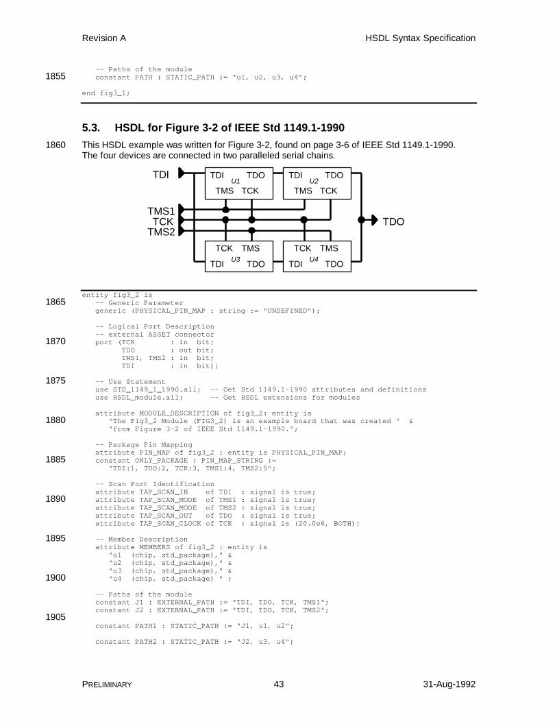
Revision A HSDL Syntax Specification
PRELIMINARY 43 31-Aug-1992
-- Paths of the module constant PATH : STATIC_PATH := "u1, u2, u3, u4";1855
end fig3_1;
5.3. HSDL for Figure 3-2 of IEEE Std 1149.1-1990This HSDL example was written for Figure 3-2, found on page 3-6 of IEEE Std 1149.1-1990.1860The four devices are connected in two paralleled serial chains.
TDI TDO
TMS TCK
TDI TDO
TMS TCK
TDI TDO
TCK TMS
TDI
TDOTMS1TCK
TDI TDO
TCK TMS
TMS2
U1 U2
U3 U4
entity fig3_2 is -- Generic Parameter1865 generic (PHYSICAL_PIN_MAP : string := "UNDEFINED");
-- Logical Port Description -- external ASSET connector port (TCK : in bit;1870 TDO : out bit; TMS1, TMS2 : in bit; TDI : in bit);
-- Use Statement1875 use STD_1149_1_1990.all; -- Get Std 1149.1-1990 attributes and definitions use HSDL_module.all; -- Get HSDL extensions for modules
attribute MODULE_DESCRIPTION of fig3_2: entity is "The Fig3_2 Module (FIG3_2) is an example board that was created " &1880 "from Figure 3-2 of IEEE Std 1149.1-1990.";
-- Package Pin Mapping attribute PIN_MAP of fig3_2 : entity is PHYSICAL_PIN_MAP; constant ONLY_PACKAGE : PIN_MAP_STRING :=1885 "TDI:1, TDO:2, TCK:3, TMS1:4, TMS2:5";
-- Scan Port Identification attribute TAP_SCAN_IN of TDI : signal is true; attribute TAP_SCAN_MODE of TMS1 : signal is true;1890 attribute TAP_SCAN_MODE of TMS2 : signal is true; attribute TAP_SCAN_OUT of TDO : signal is true; attribute TAP_SCAN_CLOCK of TCK : signal is (20.0e6, BOTH);
-- Member Description1895 attribute MEMBERS of fig3_2 : entity is "u1 (chip, std_package)," & "u2 (chip, std_package)," & "u3 (chip, std_package)," & "u4 (chip, std_package) " ;1900
-- Paths of the module constant J1 : EXTERNAL_PATH := "TDI, TDO, TCK, TMS1"; constant J2 : EXTERNAL_PATH := "TDI, TDO, TCK, TMS2";
1905 constant PATH1 : STATIC_PATH := "J1, u1, u2";
constant PATH2 : STATIC_PATH := "J2, u3, u4";
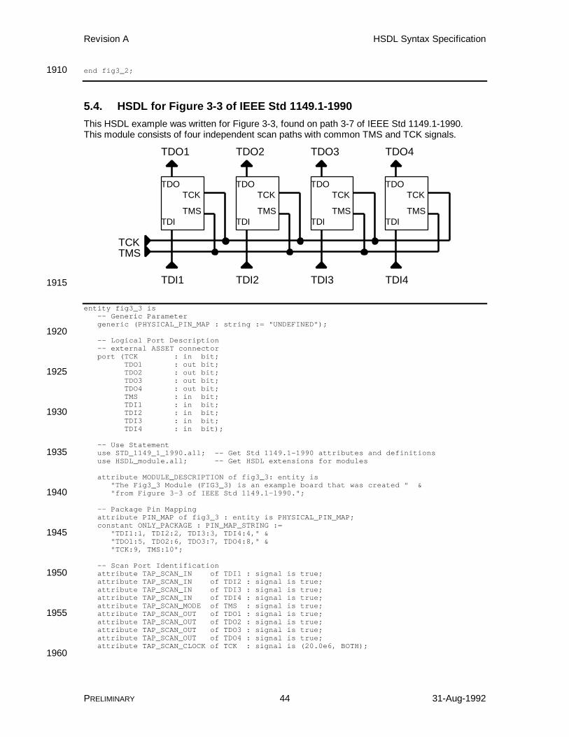
Revision A HSDL Syntax Specification
PRELIMINARY 44 31-Aug-1992
end fig3_2;1910
5.4. HSDL for Figure 3-3 of IEEE Std 1149.1-1990This HSDL example was written for Figure 3-3, found on path 3-7 of IEEE Std 1149.1-1990.This module consists of four independent scan paths with common TMS and TCK signals.
TDI1
TDO1
TMSTCK
TDI2
TDO2
TDI3
TDO3
TDI4
TDO4
TDI
TDO
TMS
TCK
TDI
TDO
TMS
TCK
TDI
TDO
TMS
TCK
TDI
TDO
TMS
TCK
1915
entity fig3_3 is -- Generic Parameter generic (PHYSICAL_PIN_MAP : string := "UNDEFINED");
1920 -- Logical Port Description -- external ASSET connector port (TCK : in bit; TDO1 : out bit; TDO2 : out bit;1925 TDO3 : out bit; TDO4 : out bit; TMS : in bit; TDI1 : in bit; TDI2 : in bit;1930 TDI3 : in bit; TDI4 : in bit);
-- Use Statement use STD_1149_1_1990.all; -- Get Std 1149.1-1990 attributes and definitions1935 use HSDL_module.all; -- Get HSDL extensions for modules
attribute MODULE_DESCRIPTION of fig3_3: entity is "The Fig3_3 Module (FIG3_3) is an example board that was created " & "from Figure 3-3 of IEEE Std 1149.1-1990.";1940
-- Package Pin Mapping attribute PIN_MAP of fig3_3 : entity is PHYSICAL_PIN_MAP; constant ONLY_PACKAGE : PIN_MAP_STRING := "TDI1:1, TDI2:2, TDI3:3, TDI4:4," &1945 "TDO1:5, TDO2:6, TDO3:7, TDO4:8," & "TCK:9, TMS:10";
-- Scan Port Identification attribute TAP_SCAN_IN of TDI1 : signal is true;1950 attribute TAP_SCAN_IN of TDI2 : signal is true; attribute TAP_SCAN_IN of TDI3 : signal is true; attribute TAP_SCAN_IN of TDI4 : signal is true; attribute TAP_SCAN_MODE of TMS : signal is true; attribute TAP_SCAN_OUT of TDO1 : signal is true;1955 attribute TAP_SCAN_OUT of TDO2 : signal is true; attribute TAP_SCAN_OUT of TDO3 : signal is true; attribute TAP_SCAN_OUT of TDO4 : signal is true; attribute TAP_SCAN_CLOCK of TCK : signal is (20.0e6, BOTH);
1960

Revision A HSDL Syntax Specification
PRELIMINARY 45 31-Aug-1992
-- Member Description attribute MEMBERS of fig3_3 : entity is "u1 (chip, std_package)," & "u2 (chip, std_package)," & "u3 (chip, std_package)," &1965 "u4 (chip, std_package) " ;
-- Paths of the module constant J1 : EXTERNAL_PATH := "TDI1, TDO1, TCK, TMS"; constant J2 : EXTERNAL_PATH := "TDI2, TDO2, TCK, TMS";1970 constant J3 : EXTERNAL_PATH := "TDI3, TDO3, TCK, TMS"; constant J4 : EXTERNAL_PATH := "TDI4, TDO4, TCK, TMS";
constant PATH1 : STATIC_PATH := "J1, u1"; constant PATH2 : STATIC_PATH := "J2, u2";1975 constant PATH3 : STATIC_PATH := "J3, u3"; constant PATH4 : STATIC_PATH := "J4, u4";
end fig3_3;
1980
5.5. HSDL for Fictional ModuleThis HSDL example was written for a fictional board. The FICTION module contains ninedevices, one SPL, one dedicated test connector, a dynamic path, and four external paths.
entity fiction is1985 -- Generic Parameter generic (PHYSICAL_PIN_MAP : string := "UNDEFINED");
-- Logical Port Description -- external ASSET connector1990 port (LCLK : inout bit; UUTCLK : out bit; TMSR : in bit; GND : linkage bit_vector (1 to 7); EVT0 : linkage bit;1995 TDI : in bit; TDO : out bit; TMS, TRST : inout bit;
-- ram32 slot connectors2000 J2_TCK, J2_TMS : inout bit; J2_TDI : out bit; J2_TDO : in bit; J2_DATABUS : inout bit_vector (31 downto 0); J2_ADDRBUS : out bit_vector (23 downto 0);2005 J2_RW : out bit;
-- backplane slot connectors (scannable VGA feature connectors!) J3_TCK, J3_TMS : inout bit; J3_TDI : out bit;2010 J3_TDO : in bit; J3_RED : out bit; J3_GRN : out bit; J3_BLU : out bit; J3_REDRTN : in bit;2015 J3_GRNRTN : in bit; J3_BLURTN : in bit; J3_HSYNC : out bit; J3_VSYNC : out bit; J3_SYNCRTN : in bit;2020 J3_ID : in bit_vector (0 to 2);
J4_TCK, J4_TMS : inout bit; J4_TDI : out bit; J4_TDO : in bit;2025 J4_RED : out bit; J4_GRN : out bit; J4_BLU : out bit; J4_REDRTN : in bit;
Revision A HSDL Syntax Specification
PRELIMINARY 46 31-Aug-1992
J4_GRNRTN : in bit;2030 J4_BLURTN : in bit; J4_HSYNC : out bit; J4_VSYNC : out bit; J4_SYNCRTN : in bit; J4_ID : in bit_vector (0 to 2);2035
J5_TCK, J5_TMS : inout bit; J5_TDI : out bit; J5_TDO : in bit; J5_RED : out bit;2040 J5_GRN : out bit; J5_BLU : out bit; J5_REDRTN : in bit; J5_GRNRTN : in bit; J5_BLURTN : in bit;2045 J5_HSYN : out bit; J5_VSYN : out bit; J5_HSYNC : out bit; J5_VSYNC : out bit; J5_SYNCRTN : in bit;2050 J5_ID : in bit_vector (0 to 2));
-- Use Statement use STD_1149_1_1990.all; -- Get Std 1149.1-1990 attributes and definitions use HSDL_module.all; -- Get HSDL extensions for modules2055
attribute MODULE_DESCRIPTION of fiction: entity is "The Fictional Module (FICTION) is an example board that was created " & "from Adam Sheppard's imagination to help define HSDL. It is the " & "motherboard for a computer. The motherboard contains an SPL, a " &2060 "manual scan path switch, and four slots. This is a MultiMedia(TM) PC.";
-- Port Descriptions attribute PORT_DESCRIPTION of EVT0 : signal is "Unimplemented event-qualification line.";2065
-- Package Pin Mapping attribute PIN_MAP of fiction : entity is PHYSICAL_PIN_MAP; constant ONLY_PACKAGE : PIN_MAP_STRING := "LCLK: J1_1, UUTCLK: J1_2, " &2070 "TDI: J1_3, TDO: J1_4, TMS: J1_5, TMSR: J1_6, TRST: J1_7," & "EVT0: J1_8, GND: (J1_9, J1_10, J1_11, J1_12, J1_13, J1_14, J1_15)" &
"J2_TCK: J2_1, J2_TMS: J2_2, J2_TDI: J2_3, J2_TDO: J2_4," & "J2_DATABUS: (J2_5, J2_6, J2_7, J2_8, J2_9, J2_10,J2_11,J2_12," &2075 "J2_13,J2_14,J2_15,J2_16,J2_17,J2_18,J2_19,J2_20," & "J2_21,J2_22,J2_23,J2_24,J2_25,J2_26,J2_27,J2_28," & "J2_29,J2_30,J2_31,J2_32,J2_33,J2_34,J2_35,J2_36)," & "J2_ADDRBUS: (J2_37,J2_38,J2_39,J2_40,J2_41,J2_42,J2_43,J2_44," & "J2_45,J2_46,J2_47,J2_48,J2_49,J2_50,J2_51,J2_52," &2080 "J2_53,J2_54,J2_55,J2_56,J2_57,J2_58,J2_59,J2_60)," & "J2_RW: J2_61," &
"J3_TCK: J3_16, J3_TMS: J3_17, J3_TDI: J3_18, J3_TDO: J3_19, " & "J3_RED: J3_1, J3_GRN: J3_2, J3_BLU: J3_3, " &2085 "J3_REDRTN: J3_6, J3_GRNRTN: J3_7, J3_BLURTN: J3_8," & "J3_HSYNC: J3_13, J3_VSYNC: J3_14, J3_SYNCRTN: J3_10, " & "J3_ID: (J3_4, J3_12, J3_11)," &
"J4_TCK: J4_16, J4_TMS: J4_17, J4_TDI: J4_18, J4_TDO: J4_19, " &2090 "J4_RED: J4_1, J4_GRN: J4_2, J4_BLU: J4_3, " & "J4_REDRTN: J4_6, J4_GRNRTN: J4_7, J4_BLURTN: J4_8," & "J4_HSYNC: J4_13, J4_VSYNC: J4_14, J4_SYNCRTN: J4_10, " & "J4_ID: (J4_4, J4_12, J4_11)," &
2095 "J5_TCK: J5_16, J5_TMS: J5_17, J5_TDI: J5_18, J5_TDO: J5_19, " & "J5_RED: J5_1, J5_GRN: J5_2, J5_BLU: J5_3, " & "J5_REDRTN: J5_6, J5_GRNRTN: J5_7, J5_BLURTN: J5_8," & "J5_HSYNC: J5_13, J5_VSYNC: J5_14, J5_SYNCRTN: J5_10, " & "J5_ID: (J5_4, J5_12, J5_11)";2100
Revision A HSDL Syntax Specification
PRELIMINARY 47 31-Aug-1992
-- Scan Port Identification attribute TAP_SCAN_IN of TDI : signal is true; attribute TAP_SCAN_MODE of TMS : signal is true; attribute TAP_SCAN_OUT of TDO : signal is true;2105 attribute TAP_SCAN_RESET of TRST : signal is true; attribute TAP_SCAN_CLOCK of LCLK : signal is (20.0e6, BOTH);
attribute TAP_SCAN_IN of J2_TDO : signal is true; attribute TAP_SCAN_MODE of J2_TMS : signal is true;2110 attribute TAP_SCAN_OUT of J2_TDI : signal is true; attribute TAP_SCAN_CLOCK of J2_TCK : signal is (20.0e6, BOTH);
attribute TAP_SCAN_IN of J3_TDO : signal is true; attribute TAP_SCAN_MODE of J3_TMS : signal is true;2115 attribute TAP_SCAN_OUT of J3_TDI : signal is true; attribute TAP_SCAN_CLOCK of J3_TCK : signal is (20.0e6, BOTH);
attribute TAP_SCAN_IN of J4_TDO : signal is true; attribute TAP_SCAN_MODE of J4_TMS : signal is true;2120 attribute TAP_SCAN_OUT of J4_TDI : signal is true; attribute TAP_SCAN_CLOCK of J4_TCK : signal is (20.0e6, BOTH);
attribute TAP_SCAN_IN of J5_TDO : signal is true; attribute TAP_SCAN_MODE of J5_TMS : signal is true;2125 attribute TAP_SCAN_OUT of J5_TDI : signal is true; attribute TAP_SCAN_CLOCK of J5_TCK : signal is (20.0e6, BOTH);
-- Member Description attribute MEMBERS of fiction : entity is2130 "u1 (i486, FK_PACKAGE)," & "u2 (sn74act8997, FK_PACKAGE)," & "u3 (sn74bct8245, FK_PACKAGE)," & "u4 (sn74bct8245, FK_PACKAGE)," & "u5 (sn74bct8245, FK_PACKAGE)," &2135 "u6 (sn74bct8245, FK_PACKAGE)," & "u7 (sn74bct8244, FK_PACKAGE)," & "u8 (sn74bct8244, FK_PACKAGE)," & "u9 (tms320c40, FK_PACKAGE)," & "u10 (sn74bct8373, FK_PACKAGE)" ;2140 attribute MEMBER_DESCRIPTION of fiction : entity is "u1 ('CPU.')," & "u2 ('The SPL is used to isolate motherboard RAM and the 32-bit slot " & "from the rest of the test logic to improve failure analysis.')," & "u3 ('Data bus between i486 and memory, lines d0-d7.')," &2145 "u4 ('Data bus between i486 and memory, lines d8-d15.')," & "u5 ('Data bus between i486 and memory, lines d16-d23.')," & "u6 ('Data bus between i486 and memory, lines d24-d32.')," & "u7 ('Chipset override control logic.')," & "u8 ('Hard disk controller override logic.')," &2150 "u9 ('DSP used to oversee multimedia functions.')," & "u10 ('Keyboard override control logic.')" ;
-- Symbol Table Descriptions2155
-- Buses of the module
-- Paths of the module constant J1 : EXTERNAL_PATH := "TDI, TDO, TMS, LCLK, TRST"; attribute PATH_DESCRIPTION of J1 : constant is2160 "J1 is the scan test connector for this board.";
constant J2 : EXTERNAL_PATH := "J2_TDI, J2_TDO, J2_TMS, J2_TCK"; constant J3 : EXTERNAL_PATH := "J3_TDI, J3_TDO, J3_TMS, J3_TCK"; constant J4 : EXTERNAL_PATH := "J4_TDI, J4_TDO, J4_TMS, J4_TCK";2165 constant J5 : EXTERNAL_PATH := "J5_TDI, J5_TDO, J5_TMS, J5_TCK";
constant subpath1 : STATIC_PATH := "u3, u4, u5, u6"; constant short : STATIC_PATH := ""; attribute PATH_DESCRIPTION of short : constant is2170 "Short is an empty static path, representing a wire between TDI and TDO.";

Revision A HSDL Syntax Specification
PRELIMINARY 48 31-Aug-1992
constant dpath : DYNAMIC_PATH := "0 (u9:dpath, short:1 )," & "1 (u9:1, short:dpath)";2175 attribute PATH_DESCRIPTION of dpath : constant is "The dynamic path dpath is used to remove the C40 from " & "the scan path if the device is not mounted on the board.";
constant boardpath : STATIC_PATH :=2180 "J1, u1, u2, u7, J3, J4, J5, u8, dpath, u10";
attribute CONNECTIONS of fiction : entity is "u2 (ssp1:subpath1, ssp2:j2, ssp3:*, ssp4:*)";
2185 -- Constraint Descriptions
end fiction;
2190
Revision A HSDL Syntax Specification
PRELIMINARY 49 31-Aug-1992
A. Hierarchical Scan Description Language Syntax
A.1. List of HSDL Statementsattribute BOUNDARY_SYMBOLS (HSDL devices) ................................................... 50attribute BUS_COMPOSITION (HSDL)..................................................................... 522195attribute BUS_DESCRIPTION (HSDL)...................................................................... 55attribute BUS_SYMBOLS (HSDL) ............................................................................ 56attribute CONNECTIONS (HSDL modules)............................................................... 57attribute CONSTRAINTS (HSDL) ............................................................................. 60attribute CONSTRAINT_DESCRIPTION (HSDL) ...................................................... 662200attribute DEVICE_DESCRIPTION (HSDL devices) ................................................... 67attribute DYNAMIC_PATH_RESET (HSDL modules) ............................................... 68attribute INSTRUCTION_DESCRIPTION (HSDL devices) ........................................ 69attribute INSTRUCTION_NORMAL (HSDL devices) ................................................. 71attribute INSTRUCTION_TEST (HSDL devices)....................................................... 722205attribute MEMBERS (HSDL modules)....................................................................... 73attribute MEMBER_DESCRIPTION (HSDL modules) ............................................... 74attribute MODULE_DESCRIPTION (HSDL modules)................................................ 75attribute PATH_DESCRIPTION (HSDL modules) ..................................................... 76attribute PORT_DESCRIPTION (HSDL) ................................................................... 772210attribute REGISTER_CAPTURE (HSDL devices) ..................................................... 78attribute REGISTER_COMPOSITION (HSDL devices) ............................................. 80attribute REGISTER_DESCRIPTION (HSDL devices) .............................................. 83attribute REGISTER_RESET (HSDL devices) .......................................................... 84attribute REGISTER_SYMBOLS (HSDL devices)..................................................... 852215attribute SYMBOL_DEFAULT (HSDL) ...................................................................... 86attribute SYMBOL_DESCRIPTION (HSDL) .............................................................. 87attribute SYMBOL_OF_TDI (HSDL).......................................................................... 88attribute SYMBOL_OF_TDO (HSDL)........................................................................ 89constant DYNAMIC_PATH (HSDL modules) ............................................................ 902220constant EXTERNAL_PATH (HSDL modules) .......................................................... 93constant STATIC_PATH (HSDL modules) ................................................................ 96constant SYMBOL_TABLE (HSDL) .......................................................................... 98use HSDL_device.all (HSDL devices) ........................................................................ 100use HSDL_module.all (HSDL modules) ..................................................................... 1012225
Revision A HSDL Syntax Specification
PRELIMINARY 50 31-Aug-1992
attribute BOUNDARY_SYMBOLS (HSDL devices)
Description This optional "attribute" statement associates a symbol table with a boundary-scan register cell attached to a device port. The TDI or TDI/TDO symbolsnamed in the symbol table can then be shifted into the specified cells, and theTDI/TDO or TDO symbols named in the symbol table can be used as2230replacements for bit patterns that are captured and shifted out of the specifiedcells. The cells "behind" the device ports can be controlled symbolically byusing names instead of numbers. Usability is increased because the testengineer no longer needs to remember the bit patterns, just the names.
For simple device ports with only one boundary-scan cell attached to them, the2235symbol table can be thought of as being associated with the device port itself.For device ports with two or more cells attached to them, the situation is morecomplex. A symbol table can be associated with each type of cell attached tothe port. For example, a simple bidirectional cell can consist of three cells: aninput cell, an output cell, and a control cell.2240
The connection between boundary-scan register cells and device ports is madein the BOUNDARY_REGISTER attribute of BSDL. The input and output cellfunctions are directly attached to the device port; the control cell is indirectlyattached to the device port through the optional <Disable Cell> portion of thecell's description. Thus, cells with the functions input, output2, output3, control,2245controlr, clock, and bidir can have a symbol table associated with them.
Internal cells cannot be associated with a symbol table using this attributebecause they are not attached to a device port. A symbol table may beassociated with an internal cell by defining a one-bit bus on that internal cell(using the BUS_COMPOSITION attribute) and associating a symbol table with2250the bus.
Syntax
attribute BOUNDARY_SYMBOLS of <device id> : entity is "<Boundary Symbol List>";
<Boundary Symbol List> is:2255<Boundary Symbol><Boundary Symbol>, <Boundary Symbol><Boundary Symbol>,...<Boundary Symbol>
<Boundary Symbol> is:<Port Name> (<Function>, <Symbol Table Name>)2260
Parameters
<device id> A <VHDL identifier> giving the name of theentity.
<Port Name> A <VHDL identifier> giving the name of apreviously defined port to associate a symbol2265table with.
<Function> A <VHDL identifier> giving the function of theport to associate a symbol table with.
<Symbol Table Name> A <VHDL identifier> giving the name of apreviously defined symbol table to attach to the2270test register. A symbol table may be attached toany number of test registers.
Revision A HSDL Syntax Specification
PRELIMINARY 51 31-Aug-1992
Examplesattribute BOUNDARY_SYMBOLS of ttl74bct8374 : entity is "CLK (input, clk_symbols)," &2275 "OC_NEG (input, oc_symbols)";
See Also attribute BUS_SYMBOLS (HSDL), attribute SYMBOL_OF_TDI (HSDL), attributeSYMBOL_OF_TDO (HSDL), constant SYMBOL_TABLE (HSDL).

Revision A HSDL Syntax Specification
PRELIMINARY 52 31-Aug-1992
attribute BUS_COMPOSITION (HSDL)
Description This optional "attribute" statement defines logical buses that may be present in2280the entity. A bus is a collection of bits from one or more test registers, chosen torepresent a natural grouping of data signals in a design. Obvious examples ofbuses include the address and data buses common to microprocessor designs.Other examples include the manufacturer, part number, and version fields of theIDCODE register, and the various status and control bits that may be present in2285internal, user-defined test data registers.
A bus can be created any time it would be more convenient or more natural torefer to scan cells in an order that differs from their physical ordering in a testregister. This can be a common requirement, given that the design and layoutof test registers is often controlled by concerns like reducing test logic overhead2290and conserving valuable "real estate". The bits in the resulting test registersmay be in an arbitrary order not corresponding to their logical meaning.
When a bus is modified by the test controller, the corresponding bits in the testregisters that make up the bus are also modified to reflect the change. Whenthe value of a bus is retrieved by the test controller, the corresponding bits in the2295test registers that make up the bus are retrieved. In this way, a bus is a logicalview into the physical test register.
Both device and module entities may define buses. A device bus is composedof subsets of one or more test registers or buses defined in the device entity. Amodule bus is similar, but the test registers and buses on which it is based can2300also be contained in module members.
Defining a bus is very similar to the method for defining concatenated testregisters, using the REGISTER_COMPOSITION attribute. The two statementsshare similar syntax.
Syntax2305
attribute BUS_COMPOSITION of <entity id> : entity is "<Bus Definition List>";
<Bus Definition List> is:<Bus Definition><Bus Definition>, <Bus Definition>2310<Bus Definition>,...<Bus Definition>
<Bus Definition> is:<Bus Name>[<Bus Width>] ( <Bus Composition> )
<Bus Width> is:<VHDL Integer>2315
<Bus Composition> is:<Bus Component><Bus Component>, <Bus Component><Bus Component>,...<Bus Component>
<Bus Component> is:2320<Bus Qualifier>.<Bus Bits><Bus Bits>
<Bus Qualifier> is:<Member Name><Member Name>.<Bus Qualifier>2325

Revision A HSDL Syntax Specification
PRELIMINARY 53 31-Aug-1992
<Bus Bits> is:<Register><Register Cell><Register Cell Range><Bus Name>2330<Bus Single Bit><Bus Bit Range>
<Bus Single Bit> is:<Bus Name> [ <Bus Bit> ]
<Bus Bit Range> is:2335<Bus Name> [ <Bus MSB>, <Bus LSB> ]
<Bus MSB> is:<Bus Bit>
<Bus LSB> is:<Bus Bit>2340
<Bus Bit> is:<VHDL Integer>
Parameters
<entity id> A <VHDL identifier> giving the name of theentity.2345
<Bus Definition> Each bus definition describes how a bus iscomposed of the cells of other test registers orbuses.
<Bus Name> A <VHDL identifier> that defines the name ofthe bus being created.2350
<Bus Width> A <VHDL Integer> that defines the width in bitsof the bus being created. The width of the newbus must be equal to the sum of the widths ofeach of the bus components.
<Bus Component> The bus component names the bits of each test2355register or bus that is a component of the busbeing defined. In a device entity, the buscomponent may not have a bus qualifier,because all test registers and buses referencedmust come from the device entity (a device has2360no members).
<Bus Qualifier> The bus qualifier names the member that thebus bits come from. If necessary, more thanone bus qualifier may be used to search deeperinto a hierarchy of members to locate the bus2365bits. The first qualifier is the name of a memberof the current module; the next qualifier is amember of that member's entity, and so forthuntil the desired module or device level in thehierarchy is reached.2370
<Bus Bits> Each set of bits in the bus can be a completetest register or bus, a one-bit subset of a testregister or bus, or a subset of a test register orbus including a range of bits.

Revision A HSDL Syntax Specification
PRELIMINARY 54 31-Aug-1992
<Register> A <VHDL identifier> giving the name of a2375previously defined test register.
<Register Cell> A single cell of a test register is a component ofthe bus.
<Register Cell Range> Multiple cells of a test register form acomponent of the bus.2380
<Bus Single Bit> A single bit of a bus is a component of the newbus.
<Bus Bit Range> Multiple cells of a bus form a component of thenew bus.
<Bus MSB> The bit offset of the bus that will be the most2385significant bit of this component of the new bus.This need not be the most significant bit of thebus bit range. If the bus MSB is less than thebus LSB, the significance of the bits arereversed in the new bus.2390
<Bus LSB> The bit offset of the bus that will be the leastsignificant bit of this component of the new bus.This need not be the least significant bit of thebus bit range. If the bus MSB is less than thebus LSB, the significance of the bits are2395reversed in the new bus.
<Bus Bit> A <VHDL Integer> giving the bit offset in thebus. 0 indicates the LSB of the bus.
Examplesattribute BUS_COMPOSITION of ttl74bct8374 : entity is2400 "inputs[8] (BOUNDARY[ 8,15])," & "outputs[8] (BOUNDARY[ 0, 7])," & "aux[2] (BOUNDARY[16,17])," & "lfsr[16] (BOUNDARY[ 0,15])";
attribute BUS_COMPOSITION of My_IC : entity is2405 "version[4] (idcode[31,28])," & "part_number[16] (idcode[27,12])," & "manufacturer[11] (idcode[11, 1])";
attribute BUS_COMPOSITION of My_Board : entity is "addrbus[32] (u1.output, u2.output, u3.output, u4.output)," &2410 "databus[32] (u5.a, u6,a, u7.a, u8.a)";
See Also Attribute IDCODE_REGISTER (BSDL), attribute MEMBERS (HSDL modules),attribute REGISTER_ACCESS (BSDL), attribute REGISTER_COMPOSITION(HSDL devices), attribute USERCODE_REGISTER (BSDL).

Revision A HSDL Syntax Specification
PRELIMINARY 55 31-Aug-1992
attribute BUS_DESCRIPTION (HSDL)2415
Description This optional "attribute" statement provides descriptions of the buses in an entity.Any or all of the buses defined in the entity may have a description. Thedescription should provide enough information to the user so that no additionaldocumentation is necessary in order to understand the use and meaning of thebus.2420
Syntax
attribute BUS_DESCRIPTION of <device id> : constant is "<Bus Descriptions>";
<Bus Descriptions> is:<Bus Description>2425<Bus Description>, <Bus Description><Bus Description>,...<Bus Description>
<Bus Description> is:<Bus Name> ('<Description>')
Parameters2430
<device id> A <VHDL identifier> giving the name of theentity.
<Bus Name> A <VHDL identifier> giving the name of apreviously defined bus. A bus may not be listedmore than once.2435
<Description> A string providing a description of the use andmeaning of the bus.
Examplesattribute BUS_DESCRIPTION of ttl74bct8374 : entity is "inputs ('The eight cells of the Boundary-Scan register " &2440 "that are connected to the D inputs are combined " & "to form the input bus.')," & "outputs ('The eight cells of the Boundary-Scan register " & "that are connected to the Q outputs are " & "combined to form the output bus.')," &2445 "aux ('The two cells of the Boundary-Scan register " & "that are connected to the CLK and OC_NEG pins " & "are combined to form the aux bus.')," & "lfsr ('The sixteen cells of the Boundary-Scan register " & "that are combined during PSA/PRPG operations to " &2450 "form the Linear Feedback Shift Register.')";
See Also constant BUS_COMPOSITION (HSDL).
Revision A HSDL Syntax Specification
PRELIMINARY 56 31-Aug-1992
attribute BUS_SYMBOLS (HSDL)
Description This optional "attribute" statement associates a symbol table with a bus. TheTDI or TDI/TDO symbols named in the symbol table can then be shifted into the2455specified bus, and the TDI/TDO or TDO symbols named in the symbol table canbe used as replacements for bit patterns that are captured and shifted out of thespecified bus. The bus can be controlled symbolically by using names instead ofnumbers. Usability is increased because the test engineer no longer needs toremember the bit patterns, just the names.2460
Syntax
attribute BUS_SYMBOLS of <device id> : entity is "<Bus Symbol List>";
<Bus Symbol List> is:<Bus Symbols>2465<Bus Symbols>, <Bus Symbols><Bus Symbols>,...<Bus Symbols>
<Bus Symbols> is:<Bus Name> ( <Symbol Table Name> )
Parameters2470
<device id> A <VHDL identifier> giving the name of theentity.
<Bus Symbol List> Each bus of the entity may have one symboltable associated with it. Neither all the busesnor all the symbol tables must be listed.2475
<Bus Name> A <VHDL identifier> giving the name of apreviously defined bus to attach a symbol tableto.
<Symbol Table Name> A <VHDL identifier> giving the name of apreviously defined symbol table to attach to the2480bus. A symbol table may be attached to anynumber of buses.
Examplesattribute BUS_SYMBOLS of ttl74bct8374 : entity is "aux (AUX_SYMBOLS)";2485
See Also attribute BUS_COMPOSITION (HSDL), attribute SYMBOL_OF_TDI (HSDL),attribute SYMBOL_OF_TDO (HSDL), constant SYMBOL_TABLE (HSDL).
Revision A HSDL Syntax Specification
PRELIMINARY 57 31-Aug-1992
attribute CONNECTIONS (HSDL modules)
Description This "attribute" statement describes how the external paths of members areconnected to the paths and devices of the current module. All external paths of2490all members must be connected to something when they are included in amodule. This improves the diagnostic abilities of the HSDL translator,preventing unconnected external paths from "slipping through" until the UUTdescription is loaded into the test controller.
If an external path is to remain unconnected (for later connection in a higher-2495level module), it can be connected to a new external path defined in the currentmodule. The decision to connect the external path can thus be postponed untilthe next higher-level module.
Syntax
attribute CONNECTIONS of <module id> : entity is2500 "<Member Path Table>";
<Member Path Table> is:<Member Path Entry><Member Path Entry>, <Member Path Entry><Member Path Entry>,...<Member Path Entry>2505
<Member Path Entry> is:<Member Name> (<External Path List>)
<External Path List> is:<External Path Entry><External Path Entry>, <External Path Entry>2510<External Path Entry>,...<External Path Entry>
<External Path Entry> is:<External Path Name> : <External Path Connection>
<External Path Connection> is:<Static Path Entry>2515*
Parameters
<module id> A <VHDL identifier> giving the name of theentity.
<Member Path Table> A string connecting the external paths of each2520member to a path or device. Every memberthat has external paths that have not alreadybeen connected to a path or device must belisted here.
<Member Path Entry> A member path entry lists the name of a2525member and a list of its external paths,attaching each to a path or device.
<External Path List> An external path list lists each external path andconnects it to a path or device. Every externalpath of the member that is not already2530connected must be listed.
<External Path Entry> An external path entry associates an externalpath of the member with a static path, dynamicpath, external path, member, or external path of

Revision A HSDL Syntax Specification
PRELIMINARY 58 31-Aug-1992
a member. The TAP signals of the static path2535entry are connected to the TAP signals of theexternal path. The external path is consideredto be driving the
<External Path Name> A <VHDL Identifier> giving the name of anexisting public external path of the member.2540
<External Path Connection> An external path connection identifies what theexternal path of the member is connected to.An external path may be connected to a staticpath, a dynamic path, an external path, amember, or an external path within a member.2545These connections model different hardwareconfigurations that might occur.
Connecting an external path to a deviceindicates that the external path was probably achip socket.2550
Connecting an external path to a moduleindicates that the external path was probably adaughterboard connector or a backplaneconnector.
Connecting an external path to a static path2555indicates that the member controlling theexternal path is probably a device or modulewith a secondary scan path. A secondary scanpath is a slave path that can be configured inand out of the scan path by scanning commands2560to the master. The Texas InstrumentsSN74ACT8997 Scan Path Linker andSN74ACT8999 Scan Path Selector areexamples of such devices. An example of amodule like this might be a multi-chip module2565that controls a secondary scan path.
Connecting an external path to a dynamic pathor a member's external path is simply a morecomplicated example of connecting an externalpath to a static path.2570
Connecting an external path to an external pathdefined in the current module is the method forpostponing the connection to a higher-levelmodule.
An asterisk (*) denotes an external path that is2575"open". Such an external path is not connectedto any scannable hardware, and thus cannot bescanned through. The test controller can thenprevent the use of any scan paths including thisexternal path. This facility is useful for2580members whose external paths are controlledby a dynamic path. Examples include the TISN74ACT8997 and SN74ACT8999 scan pathlinkers and selector that control secondary scanpaths. If an external path of these devices is2585not connected, the test controller should
Revision A HSDL Syntax Specification
PRELIMINARY 59 31-Aug-1992
disallow the selection of that case in thedynamic path of the device.
Every external path of every member must beconnected to something. This connection may2590be a short (an empty static path), somethingscannable (a path, member, or member externalpath), or nothing at all (an asterisk). Theconnection can be accomplished by placing themember in a STATIC_PATH or2595DYNAMIC_PATH list, or by listing the memberin the CONNECTIONS attribute.
A member's external path must be connected toan external path defined in the current modulein order to leave the connection undefined, so2600that it may be connected in a higher-levelmodule.
Examplesconstant subpath1 : STATIC_PATH := "u1, u2";constant subpath2 : STATIC_PATH := "u3, u4, u5";2605-- Attach subpath 1/2 to secondary scan path 1/3 of SN74ACT8997-- Leave secondary scan path 2/4 permanently unconnectedattribute CONNECTIONS of My_Board : entity is "u9 (ssp1:subpath1, ssp2:*, ssp3:subpath2, ssp4:*)";
See Also constant DYNAMIC_PATH (HSDL modules), constant EXTERNAL_PATH2610(HSDL modules), constant STATIC_PATH (HSDL modules).
Revision A HSDL Syntax Specification
PRELIMINARY 60 31-Aug-1992
attribute CONSTRAINTS (HSDL)
Description This optional "attribute" statement describes illegal conditions (constraints) of thehardware, conditions that the test controller is not allowed to create by scanningbit patterns into the hardware. These constraints usually mirror those that are2615prevented by design in the normal, functional mode of the hardware, but whichcan be easily circumvented using scan.
An example of a typical constraint is preventing more than one driver at a timefrom driving onto a bus. Usually, the hardware is specifically designed toprevent this occurrence. However, since boundary scan can take over the2620operation of the hardware, the hardware design that prevented two drivers fromdriving onto the bus is now overridden by scan. Constraints can be coded intothe HSDL entity to repeat the same constraints designed into the hardware, thuspreventing damage.
Constraints are written in the form of logical expressions that must evaluate to2625FALSE before a scan operation is allowed to take place. Each constraint isevaluated against the data to be shifted in, and if any of the constraints is TRUE,the test controller stops scanning and informs the operator that a constraint hasbeen violated. The operation in progress is aborted, and scanning is forbiddenuntil once again all constraints evaluate to FALSE.2630
Logical expressions are used in preference to illegal bit patterns, because the bitpatterns could be quite lengthy and redundant. If a specific bit pattern isconsidered illegal, it can be checked for with an expression. Thus, expressionsare more "expressive".
Constraints can appear in both device and module entities. Module constraints2635are often related to bus drivers, and tend to prevent conflicts between devices.Device constraints may take the form of values that should not be scanned intocertain test registers or specific combinations of values in different test registers.Private instructions represent a form of constraint, in that a private instruction isa bit pattern that can never be scanned into the instruction register.2640
A constraint can use the operators shown in the following table. In many ways,these operators are like their counterparts in VHDL. The precedence,associativity, and meaning is the same. The operand values and their resultsdiffer, because the values in HSDL can include don't-care bits.
2645

Revision A HSDL Syntax Specification
PRELIMINARY 61 31-Aug-1992
Operators
Operator Rank Descriptiona AND b 6 Logical ANDa OR b 6 Logical Inclusive OR
a XOR b 6 Logical Exclusive ORa NAND b 6 Logical Negated ANDa NOR b 6 Logical Negated OR
a = b 5 Relational Equalitya <> b 5 Relational Inequalitya < b 5 Relational Less Thana > b 5 Relational Greater Than
a <= b 5 Relational Less Than or Equala >= b 5 Relational Greater Than or Equala + b 4 Arithmetic Additiona - b 4 Arithmetic Subtraction- a 3 Arithmetic Negation
a * b 2 Arithmetic Multiplicationa / b 2 Arithmetic Division
NOT a 1 Logical Negation
Operators fall into the following groups: logical, relational, or arithmetic, and areshown in order of increasing precedence. Precedence defines the order ofevaluation of operators. Operators with higher precedence are evaluated before2650operators with lower precedence. In the table, the logical negation operator(NOT) has the highest precedence with rank 1, and the other logical operatorshave the lowest precedence with rank 6. Most operators at the sameprecedence level evaluate their operands left-to-right. The exceptions are thelogical negation (NOT) and arithmetic negation (-) operators, which are2655evaluated right-to-left. Parentheses can be used to override the usual order ofevaluation.
An associative operator is one where the left and right operands can beexchanged without changing the result. The associative operators are identifiedin the discussion of each operator.2660
The logical operators are AND, OR, XOR, NAND, NOR, and NOT. All but NOTare associative operators. The logical operators are applied to each bit of theoperands to determine the result. Their results are shown in the following tables.
Logical Operators
2665a b a AND b a OR b a XOR b a NAND b a NOR b1 1 1 1 0 0 01 0 0 1 1 1 00 0 0 0 0 1 1
a NOT a1 00 1
The relational operators are =, <>, <, >, <=, >=. Only = and <> are associativeoperators. The relational operators are applied to all bits of the operand to
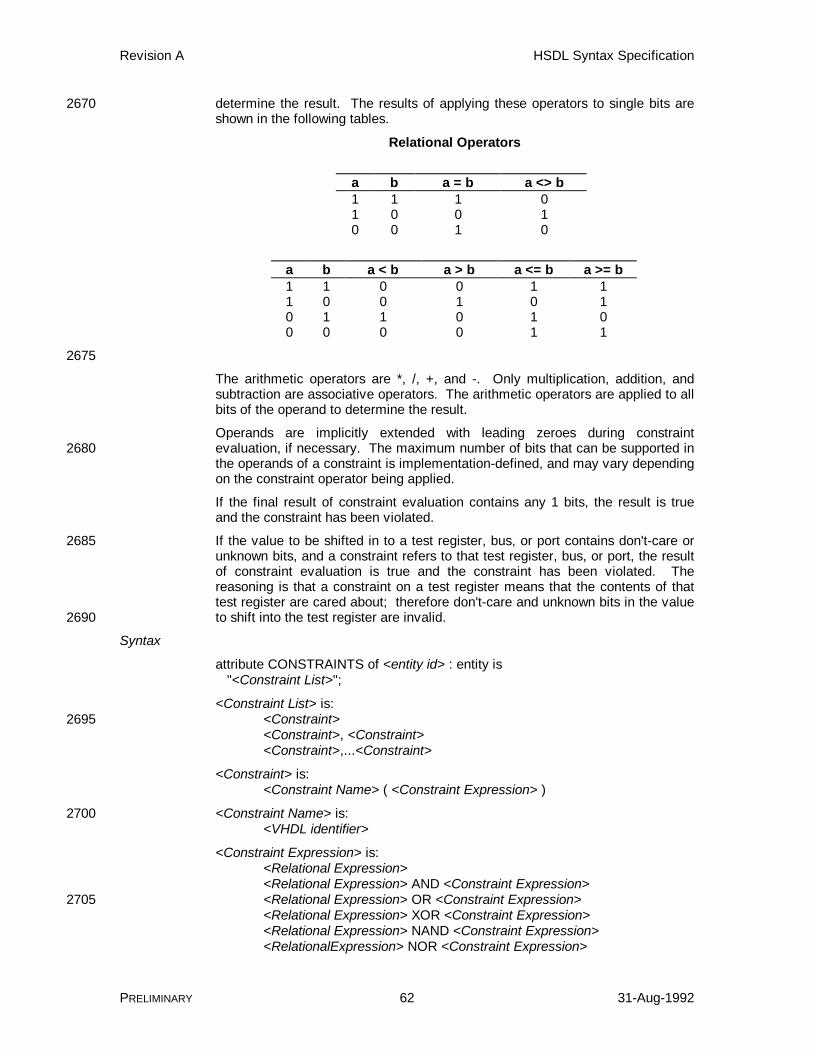
Revision A HSDL Syntax Specification
PRELIMINARY 62 31-Aug-1992
determine the result. The results of applying these operators to single bits are2670shown in the following tables.
Relational Operators
a b a = b a <> b1 1 1 01 0 0 10 0 1 0
a b a < b a > b a <= b a >= b1 1 0 0 1 11 0 0 1 0 10 1 1 0 1 00 0 0 0 1 1
2675
The arithmetic operators are *, /, +, and -. Only multiplication, addition, andsubtraction are associative operators. The arithmetic operators are applied to allbits of the operand to determine the result.
Operands are implicitly extended with leading zeroes during constraintevaluation, if necessary. The maximum number of bits that can be supported in2680the operands of a constraint is implementation-defined, and may vary dependingon the constraint operator being applied.
If the final result of constraint evaluation contains any 1 bits, the result is trueand the constraint has been violated.
If the value to be shifted in to a test register, bus, or port contains don't-care or2685unknown bits, and a constraint refers to that test register, bus, or port, the resultof constraint evaluation is true and the constraint has been violated. Thereasoning is that a constraint on a test register means that the contents of thattest register are cared about; therefore don't-care and unknown bits in the valueto shift into the test register are invalid.2690
Syntax
attribute CONSTRAINTS of <entity id> : entity is "<Constraint List>";
<Constraint List> is:<Constraint>2695<Constraint>, <Constraint><Constraint>,...<Constraint>
<Constraint> is:<Constraint Name> ( <Constraint Expression> )
<Constraint Name> is:2700<VHDL identifier>
<Constraint Expression> is:<Relational Expression><Relational Expression> AND <Constraint Expression><Relational Expression> OR <Constraint Expression>2705<Relational Expression> XOR <Constraint Expression><Relational Expression> NAND <Constraint Expression><RelationalExpression> NOR <Constraint Expression>
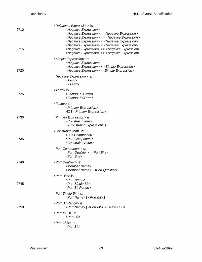
Revision A HSDL Syntax Specification
PRELIMINARY 63 31-Aug-1992
<Relational Expression> is:<Negative Expression>2710<Negative Expression> = <Negative Expression><Negative Expression> <> <Negative Expression><Negative Expression> < <Negative Expression><Negative Expression> > <Negative Expression><Negative Expression> <= <Negative Expression>2715<Negative Expression> >= <Negative Expression>
<Simple Expression> is:<Negative Expression><Negative Expression> + <Simple Expression><Negative Expression> - <Simple Expression>2720
<Negative Expression> is:<Term>- <Term>
<Term> is:<Factor> * <Term>2725<Factor> / <Term>
<Factor> is:<Primary Expression>NOT <Primary Expression>
<Primary Expression> is:2730<Constraint Item>( <Constraint Expression> )
<Constraint Item> is:<Bus Component><Port Component>2735<Constraint Value>
<Port Component> is:<Port Qualifier> . <Port Bits><Port Bits>
<Port Qualifier> is:2740<Member Name><Member Name> . <Port Qualifier>
<Port Bits> is:<Port Name><Port Single Bit>2745<Port Bit Range>
<Port Single Bit> is:<Port Name> [ <Port Bit> ]
<Port Bit Range> is:<Port Name> [ <Port MSB>, <Port LSB> ]2750
<Port MSB> is:<Port Bit>
<Port LSB> is:<Port Bit>

Revision A HSDL Syntax Specification
PRELIMINARY 64 31-Aug-1992
<Port Bit> is:2755<VHDL Integer>
<Constraint Value> is:<Pattern><Symbol Name>
Parameters2760
<entity id> A <VHDL identifier> giving the name of theentity.
<Constraint Name> A <VHDL identifier> defining the name of a newconstraint. This name is used by the testcontroller when it informs the operator that a2765constraint has been violated.
<Constraint Expression> A logical expression that may include logicaloperators to check combinations of values.When the expression evaluates to TRUE, thetest controller halts and informs the operator2770that the constraint with the specified name hasbeen violated.
<Relational Expression> An expression that checks for equality orordering of a constraint item and a constraintvalue.2775
<Simple Expression> An expression that adds or subtracts aconstraint item and a constraint value.
<Negative Expression> An expression that inverts the sign of aconstraint item or a constraint value.
<Term> An expression that multiplies or divides a2780constraint item and a constraint value.
<Factor> An expression that inverts the bits of aconstraint item or a constraint value.
<Primary Expression> A constraint item2785specifying scan cells to check. The primaryexpression may also be a parenthesizedconstraint expression, so that the usualevaluation order may be overridden.
<Constraint Item> The constraint item specifies which bits are to2790be checked before shifting in, and can specifyall or part of a test register, bus, or port. Theconstraint item may be contained in a member.
<Bus Component> The bus component names the bits of a testregister or bus that is checked by the constraint2795expression. In a device entity, the buscomponent may not have a bus qualifier,because all test registers and buses referencedmust come from the device entity (a device hasno members). See attribute2800BUS_COMPOSITION (HSDL) for more details.
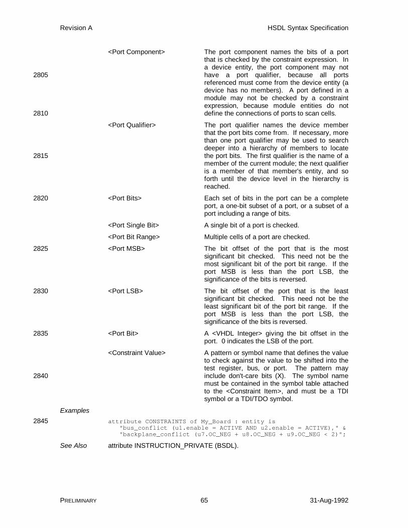
Revision A HSDL Syntax Specification
PRELIMINARY 65 31-Aug-1992
<Port Component> The port component names the bits of a portthat is checked by the constraint expression. Ina device entity, the port component may nothave a port qualifier, because all ports2805referenced must come from the device entity (adevice has no members). A port defined in amodule may not be checked by a constraintexpression, because module entities do notdefine the connections of ports to scan cells.2810
<Port Qualifier> The port qualifier names the device memberthat the port bits come from. If necessary, morethan one port qualifier may be used to searchdeeper into a hierarchy of members to locatethe port bits. The first qualifier is the name of a2815member of the current module; the next qualifieris a member of that member's entity, and soforth until the device level in the hierarchy isreached.
<Port Bits> Each set of bits in the port can be a complete2820port, a one-bit subset of a port, or a subset of aport including a range of bits.
<Port Single Bit> A single bit of a port is checked.
<Port Bit Range> Multiple cells of a port are checked.
<Port MSB> The bit offset of the port that is the most2825significant bit checked. This need not be themost significant bit of the port bit range. If theport MSB is less than the port LSB, thesignificance of the bits is reversed.
<Port LSB> The bit offset of the port that is the least2830significant bit checked. This need not be theleast significant bit of the port bit range. If theport MSB is less than the port LSB, thesignificance of the bits is reversed.
<Port Bit> A <VHDL Integer> giving the bit offset in the2835port. 0 indicates the LSB of the port.
<Constraint Value> A pattern or symbol name that defines the valueto check against the value to be shifted into thetest register, bus, or port. The pattern mayinclude don't-care bits (X). The symbol name2840must be contained in the symbol table attachedto the <Constraint Item>, and must be a TDIsymbol or a TDI/TDO symbol.
Examplesattribute CONSTRAINTS of My_Board : entity is2845 "bus_conflict (u1.enable = ACTIVE AND u2.enable = ACTIVE)," & "backplane_conflict (u7.OC_NEG + u8.OC_NEG + u9.OC_NEG < 2)";
See Also attribute INSTRUCTION_PRIVATE (BSDL).
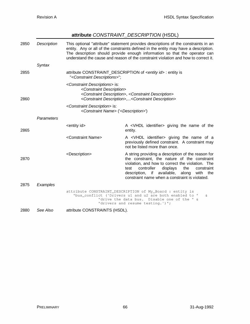
Revision A HSDL Syntax Specification
PRELIMINARY 66 31-Aug-1992
attribute CONSTRAINT_DESCRIPTION (HSDL)
Description This optional "attribute" statement provides descriptions of the constraints in an2850entity. Any or all of the constraints defined in the entity may have a description.The description should provide enough information so that the operator canunderstand the cause and reason of the constraint violation and how to correct it.
Syntax
attribute CONSTRAINT_DESCRIPTION of <entity id> : entity is2855 "<Constraint Descriptions>";
<Constraint Descriptions> is:<Constraint Description><Constraint Description>, <Constraint Description><Constraint Description>,...<Constraint Description>2860
<Constraint Description> is:<Constraint Name> ('<Description>')
Parameters
<entity id> A <VHDL identifier> giving the name of theentity.2865
<Constraint Name> A <VHDL identifier> giving the name of apreviously defined constraint. A constraint maynot be listed more than once.
<Description> A string providing a description of the reason forthe constraint, the nature of the constraint2870violation, and how to correct the violation. Thetest controller displays the constraintdescription, if available, along with theconstraint name when a constraint is violated.
Examples2875attribute CONSTRAINT_DESCRIPTION of My_Board : entity is "bus_conflict ('Drivers u1 and u2 are both enabled to " & "drive the data bus. Disable one of the " & "drivers and resume testing.')";
See Also attribute CONSTRAINTS (HSDL).2880
Revision A HSDL Syntax Specification
PRELIMINARY 67 31-Aug-1992
attribute DEVICE_DESCRIPTION (HSDL devices)
Description This optional "attribute" statement may appear following the "use" statements,and can be used to describe the type of the device itself. This description canbe used to partially meet Documentation Requirement 12.3.1.a of IEEE Std1149.1-1990.2885
Syntax
attribute DEVICE_DESCRIPTION of <device id> : entity is "<Device Description>";
Parameters
<device id> A <VHDL identifier> giving the name of the2890entity.
<Device Description> A text string describing the device. The stringmay be arbitrarily long. No specific meaning isattached to its contents. The string shouldcontain information describing the overall2895operation of the device, and may be used by theengineer to gain an understanding of themodule. Tools may display this string whenqueried about the device.
Examples2900attribute DEVICE_DESCRIPTION of My_IC : entity is "My_IC is a two-bit adder that computes the sum " & "of A and B on the rising edge of CLK.";
See Also attribute MODULE_DESCRIPTION (HSDL modules)
Revision A HSDL Syntax Specification
PRELIMINARY 68 31-Aug-1992
attribute DYNAMIC_PATH_RESET (HSDL modules)2905
Description This "attribute" statement describes what happens to a dynamic path when theUUT passes through the Test-Logic-Reset state of the TAP state diagram. Thestate of the hardware controlling the dynamic path may be altered when thishappens. If the hardware controlling the dynamic path happens to be ascannable device, the device will be placed in a normal mode and the2910configuration of the dynamic path will change.
If the dynamic path does not change state when the UUT passes through Test-Logic-Reset, a DYNAMIC_PATH_RESET attribute is not needed.
Syntax
attribute DYNAMIC_PATH_RESET of <Dynamic Path Name> : constant is2915 "<Dynamic Case Value>";
Parameters
<Dynamic Path Name> A <VHDL identifier> giving the name of apreviously defined dynamic path.
<Dynamic Case Value> A <VHDL Integer> specifying which case value2920of the dynamic path becomes active when theUUT is reset. The integer must match one ofthe dynamic case values of the dynamic pathnamed by this statement. This case value alsospecifies the initial state of the dynamic path,2925because the UUT is in Test-Logic-Reset state onpower-up.
Examplesattribute DYNAMIC_PATH_RESET of c40switch : constant is "1";
See Also attribute REGISTER_RESET (HSDL devices), constant DYNAMIC_PATH2930(HSDL modules).

Revision A HSDL Syntax Specification
PRELIMINARY 69 31-Aug-1992
attribute INSTRUCTION_DESCRIPTION (HSDL devices)
Description This optional "attribute" statement describes the function and purpose of theinstruction opcodes of a device. The description can be used to meet the IEEEStd. 1149.1-1990 Documentation Requirement 12.3.1.b.ii. It should describe the2935operation of the instruction, any initialization needed, test registers altered,algorithms employed, and so forth. The description should be complete enoughto use the instruction without additional documentation.
An instruction description is not required for the predefined instructions in IEEEStd 1149.1-1990 and Supplement A. These include SAMPLE/PRELOAD,2940EXTEST, INTEST, BYPASS, RUNBIST, CLAMP, and HIGHZ. An appropriatedescription is created for each of these instructions if no description is defined inthe entity.
If the instructions INTEST and RUNBIST are available in the device, adescription should be supplied by the user in lieu of the one created by the2945HSDL translator. The INTEST and RUNBIST instructions have many design-specific parameters that cannot be adequately described in HSDL.
Syntax
attribute INSTRUCTION_DESCRIPTION of <device id> : entity is "<Instruction Description Table>";2950
<Instruction Description Table> is:<Instruction Description Entry><Instruction Description Entry>, <Instruction Description Entry><Instruction Description Entry>,...<Instruction Description Entry>
<Instruction Description Entry> is:2955<Opcode Name> ('<Instruction Description>')
Parameters
<device id> A <VHDL identifier> giving the name of theentity.
<Instruction Description Table> This parameter is a string containing instruction2960opcode names and associated descriptions.
<Instruction Description Entry> Each instruction description entry associates aninstruction opcode with a description.
<Opcode Name> The opcode name gives the name of aninstruction opcode previously defined in the2965INSTRUCTION_OPCODE attribute. An opcodename need not appear in the instructiondescription, but each opcode name may onlyappear once.
<Instruction Description> A string describing the operation of the2970associated opcode. The string may bearbitrarily long. No specific meaning is attachedto its contents. The string should containinformation describing the overall operation ofthe module, and may be used by the engineer to2975gain an understanding of the module. Toolsmay display this string when queried about themodule.
Revision A HSDL Syntax Specification
PRELIMINARY 70 31-Aug-1992
Examplesattribute INSTRUCTION_DESCRIPTION of My_IC : entity is2980 "EXTEST ('Select Boundary-Scan register in test mode; " & "control device inputs and outputs using the " & "contents of the Boundary.')," & "TRIBYP ('Select BYPASS register in test mode; " & "control device outputs to high-impedance.')" ;2985
See Also attribute INSTRUCTION_DISABLE (BSDL), attribute INSTRUCTION_GUARD(BSDL), attribute INSTRUCTION_NORMAL (HSDL), attributeINSTRUCTION_OPCODE (BSDL), attribute INSTRUCTION_TEST (HSDL).

Revision A HSDL Syntax Specification
PRELIMINARY 71 31-Aug-1992
attribute INSTRUCTION_NORMAL (HSDL devices)
Description This optional "attribute" statement identifies instruction opcodes of the device2990that do not affect the normal operation of the device in any way. The devicecontinues to operate as if the test circuitry was inactive.
Instruction opcodes can be classified in three ways: normal-mode, test-mode,and unknown. A normal-mode instruction is one that does not affect the normaloperation of the device, and is identified by listing it in the2995INSTRUCTION_NORMAL attribute. A test-mode instruction is one that affectsthe normal operation in some way by placing the device into a test mode, and isidentified by listing it in the INSTRUCTION_TEST attribute. An instructionwhose effects are not known cannot be listed in either attribute, so it is"unknown" whether the device operates in test or normal mode when it is loaded.3000
The instructions BYPASS, SAMPLE, IDCODE, and USERCODE, defined by1149.1, must be normal-mode instructions and do not need to be listed in theINSTRUCTION_NORMAL attribute.
Syntax
attribute INSTRUCTION_NORMAL of <device id> : entity is3005 "<Instruction List>";
<Instruction List> is:<Instruction Name><Instruction Name>,...<Instruction Name>
Parameters3010
<device id> A <VHDL identifier> giving the name of theentity.
<Instruction Name> A <VHDL identifier> giving the name of apreviously defined instruction opcode which isclassified as a normal-mode instruction. An3015instruction opcode cannot appear more thanonce. An instruction opcode cannot appear inboth the INSTRUCTION_NORMAL attribute andthe INSTRUCTION_TEST attribute.
Examples3020attribute INSTRUCTION_NORMAL of ttl74bct8374 : entity is "BYPASS, SAMPLE, READBN, CELLTST, SCANCN";
See Also attribute INSTRUCTION_OPCODE (BSDL), attribute INSTRUCTION_TEST(HSDL devices).

Revision A HSDL Syntax Specification
PRELIMINARY 72 31-Aug-1992
attribute INSTRUCTION_TEST (HSDL devices)3025
Description This optional "attribute" statement identifies instruction opcodes of the devicethat affect the normal operation of the device in some way. All or part of thenormal operation of the device is suspended and replaced with a test operation.
Instruction opcodes can be classified in three ways: normal-mode, test-mode,and unknown. A normal-mode instruction is one that does not affect the normal3030operation of the device, and is identified by listing it in theINSTRUCTION_NORMAL attribute. A test-mode instruction is one that affectsthe normal operation in some way by placing the device into a test mode, and isidentified by listing it in the INSTRUCTION_TEST attribute. An instructionwhose effects are not known cannot be listed in either attribute, so it is3035"unknown" whether the device operates in test or normal mode when it is loaded.
Whether a test-mode instruction affects the device output pins or affects theinputs to the device system logic is unspecified; in other words, the exact natureof the test mode is not described. A test-mode instruction is simply one thatalters the device in some way.3040
The instructions EXTEST, INTEST, RUNBIST, HIGHZ, and CLAMP, defined by1149.1, must be test-mode instructions and do not need to be listed in theINSTRUCTION_TEST attribute. Note that although 1149.1 does not specify theexact nature of system logic inputs and device outputs for these instructions, itdoes specify that they alter the normal operation of the device.3045
The instructions listed in the INSTRUCTION_DISABLE andINSTRUCTION_GUARD attributes must be test-mode instructions, but do notneed to be listed in the INSTRUCTION_TEST attribute.
Syntax
attribute INSTRUCTION_TEST of <device id> : entity is3050 "<Instruction List>";
<Instruction List> is:<Instruction Name><Instruction Name>,...<Instruction Name>
Parameters3055
<device id> A <VHDL identifier> giving the name of theentity.
<Instruction Name> A <VHDL identifier> giving the name of apreviously defined instruction opcode which isclassified as a test-mode instruction. An3060instruction opcode cannot appear more thanonce. An instruction opcode may not appear inboth the INSTRUCTION_NORMAL attribute andthe INSTRUCTION_TEST attribute.
Examples3065attribute INSTRUCTION_TEST of ttl74bct8374 : entity is "EXTEST, INTEST, TRIBYP, SETBYP," & "RUNT, READBT, TOPHIP, SCANCT" ;
See Also attribute INSTRUCTION_DISABLE (BSDL), attribute INSTRUCTION_GUARD(BSDL), attribute INSTRUCTION_NORMAL (HSDL devices), attribute3070INSTRUCTION_OPCODE (BSDL)

Revision A HSDL Syntax Specification
PRELIMINARY 73 31-Aug-1992
attribute MEMBERS (HSDL modules)
Description This optional "attribute" statement identifies the members of the module.Members are the devices and submodules that are wired together to create themodule. Each member has a unique name and is a certain type of device or3075module using a specific packaging option.
A module does not have to contain member devices or modules. One exampleof such a module is a dummy board that simply contains a short from TDI toTDO. Another, more realistic example is a system backplane that contains noscannable devices, only scannable card slots.3080
Syntax
attribute MEMBERS of <module id> : entity is "<Member Table>";
<Member Table> is:<Member Entry>3085<Member Entry>, <Member Entry><Member Entry>, ... <Member Entry>
<Member Entry> is:<Member Name> (<Entity Name> <Package Name>)
Parameters3090
<module id> A <VHDL identifier> giving the name of theentity.
<Member Table> This parameter is a string containing memberdefinitions.
<Member Entry> Each Member Entry parameter defines one of3095the members of the module, its name, its type(entity), and its package.
<Member Name> A <VHDL identifier> defining a unique, user-selected name for the member.
<Entity Name> The name of an existing entity, described in3100another HSDL or BSDL file.
<Package Name> The name of a package defined as aPIN_MAP_STRING constant in the entity givenby Entity Name.
Examples3105attribute MEMBERS of My_Board : entity is "u1 (sn74bct8245, FK_PACKAGE)," & "u2 (sn74bct8240, DW_PACKAGE) " ;
See Also entity (BSDL), constant-(entity) (BSDL).
Revision A HSDL Syntax Specification
PRELIMINARY 74 31-Aug-1992
attribute MEMBER_DESCRIPTION (HSDL modules)3110
Description This optional "attribute" statement can be used to describe the purpose of eachof the members of a module.
Syntax
attribute MEMBER_DESCRIPTION of <module id> : entity is "<Member Description Table>";3115
<Member Description Table> is:<Member Description Entry><Member Description Entry>, <Member Description Entry><Member Description Entry>,...<Member Description Entry>
<Member Description Entry> is:3120<Member Name> ('<Member Description>')
Parameters
<module id> A <VHDL identifier> giving the name of theentity.
<Member Description Table> This parameter is a string that associates a3125description with one or more of the modulemembers.
<Member Description Entry> Each Member Description Entry gives the nameof a member and associates a comment withthat member.3130
<Member Name> A <VHDL identifier> that gives the name of oneof the members defined in the MEMBERSattribute. Each Member Name may appear nomore than once in the <Member DescriptionTable>. Not every member needs to have a3135description associated with it.
<Member Description> A text string describing the member. The stringmay be arbitrarily long. No specific meaning isattached to its contents. The string shouldcontain information describing the purpose of3140the member in the module, and may be used bythe engineer to gain an understanding of themodule. Tools may display this string whenqueried about the member.
Examples3145attribute MEMBER_DESCRIPTION of My_Board : entity is "u1 ('The 245 in U1 is used as a backplane driver.')," & "u2 ('The 240 in U2 inverts the panel switches.')" ;
See Also attribute DEVICE_DESCRIPTION (HSDL devices), attribute MEMBERS (HSDLmodules), attribute MODULE_DESCRIPTION (HSDL modules).3150

Revision A HSDL Syntax Specification
PRELIMINARY 75 31-Aug-1992
attribute MODULE_DESCRIPTION (HSDL modules)
Description This optional "attribute" statement may appear following the "use" statements,and can be used to describe the type of the module itself. This description canbe used to partially meet Documentation Requirement 12.3.1.a of IEEE Std1149.1-1990.3155
Syntax
attribute MODULE_DESCRIPTION of <module id> : entity is "<Module Description>";
Parameters
<module id> A <VHDL identifier> giving the name of the3160entity.
<Module Description> A text string describing the module. The stringmay be arbitrarily long. No specific meaning isattached to its contents. The string shouldcontain information describing the overall3165operation of the module, and may be used bythe engineer to gain an understanding of themodule. Tools may display this string whenqueried about the module.
Examples3170attribute MODULE_DESCRIPTION of My_Board : entity is "My_Board contains four megabytes of RAM, with a " & "32-bit address bus and 32-bit data bus.";
See Also attribute DEVICE_DESCRIPTION (HSDL devices).
Revision A HSDL Syntax Specification
PRELIMINARY 76 31-Aug-1992
attribute PATH_DESCRIPTION (HSDL modules)3175
Description This optional "attribute" statement can be used to describe the purpose andfunction of each of the paths of the module. A separate path description is usedto describe each of the paths of the module.
Syntax
attribute PATH_DESCRIPTION of <Path Name> : constant is3180 "<Path Description>";
<Path Name> is:<Static Path Name><Dynamic Path Name><External Path Name>3185
Parameters
<Path Name> A <VHDL identifier> giving the name of one ofthe static, dynamic, or external paths defined inthe module. Each path can have at most onedescription attached to it.3190
<Path Description> A string describing the purpose and function ofthe path, and may be used by the engineer togain an understanding of the module.. Thestring may be arbitrarily long. No specificmeaning is attached to its contents. Tools may3195display this string when queried about the path.
Examplesattribute PATH_DESCRIPTION of J1 : constant is "J1 is the scan test connector for this board.";
attribute PATH_DESCRIPTION of short : constant is3200 "Short is an empty static path, representing a wire " & "between TDI and TDO.";
attribute PATH_DESCRIPTION of dpath : constant is "The dynamic path dpath is used to remove the C40 from " & "the scan path if the device is not mounted on the board.";3205
See Also constant DYNAMIC_PATH (HSDL modules), constant EXTERNAL_PATH(HSDL modules), constant STATIC_PATH (HSDL modules).
Revision A HSDL Syntax Specification
PRELIMINARY 77 31-Aug-1992
attribute PORT_DESCRIPTION (HSDL)
Description This optional "attribute" statement can be used to describe the purpose andfunction of each of the ports of the entity (device or module). A separate port3210description is used to describe each of the ports of the entity.
A port description is not required for the scan ports of the entity. Scan ports arethose identified in the TAP_SCAN_IN, TAP_SCAN_OUT, TAP_SCAN_CLOCK,TAP_SCAN_MODE, and TAP_SCAN_RESET attributes. An appropriatedescription is created for each of the scan ports if none is defined in the entity.3215
Syntax
attribute PORT_DESCRIPTION of <Port Name> : signal is "<Port Description>";
Parameters
<Port Name> A <VHDL identifier> giving the name of one of3220the ports.
<Port Description> A string describing the purpose and function ofthe port. The string should describe thefunctional operation of the port, not the testoperation. The string may be arbitrarily long.3225No specific meaning is attached to its contents.The string should contain information describingthe overall operation of the module, and may beused by the engineer to gain an understandingof the module. Tools may display this string3230when queried about the module.
Examplesattribute PORT_DESCRIPTION of Q : signal is "Eight-bit output bus of the device. All outputs can be " & "set to high-impedance by placing a 1 on the OC_NEG pin. " &3235 "All outputs can be updated with the values on the input " & "bus D on a positive transition of CLK.";
See Also attribute TAP_SCAN_CLOCK (BSDL), attribute TAP_SCAN_IN (BSDL), attributeTAP_SCAN_MODE (BSDL), attribute TAP_SCAN_OUT (BSDL), attributeTAP_SCAN_RESET (BSDL), port (BSDL).3240
Revision A HSDL Syntax Specification
PRELIMINARY 78 31-Aug-1992
attribute REGISTER_CAPTURE (HSDL devices)
Description This optional "attribute" statement describes the possible values that a testregister of a device can capture, along with a description and an indication ofwhether each value represents a pass or failure value. This attachesrudimentary diagnostic ability to a test register and can be useful for test3245registers that capture a status value. The BSDL attributeINSTRUCTION_CAPTURE provides this ability for the instruction register.
Values captured by a test register that are not listed in theREGISTER_CAPTURE attribute are considered don't-care values; that is, theyare neither pass nor failure values.3250
Syntax
attribute REGISTER_CAPTURE of <device id> : entity is "<Register Capture List>";
<Register Capture List> is:<Register Capture>3255<Register Capture>, <Register Capture><Register Capture>,...<Register Capture>
<Register Capture> is:<Register> ( <Capture Value> , <Pass Fail> )<Register> ( <Capture Value> , <Pass Fail> , '<Capture Description>' )3260
<Capture Value> is:<Pattern><Symbol Name>
<Pass Fail> is:PASS3265FAIL
Parameters
<device id> A <VHDL identifier> giving the name of theentity.
<Register Capture List> A string describing the capture values of each3270test register. A test register may appear morethan once in the list, to describe all pass and failvalues.
<Register> A <VHDL identifier> giving the name of apreviously defined test register.3275
<Capture Value> A value captured by the test register.Ambiguous values are not allowed. Ambiguousvalues are values containing don't-care bitssuch that two different values could representthe same binary pattern. In this case, ambiguity3280could arise from two conflicting patterns, or froma pattern and a symbol representing the samevalue. Undefined capture values for a testregister are assumed to be Fail values.
<Pattern> A bit pattern, optionally containing Xs to3285represent don't-care bits, that is captured by the
Revision A HSDL Syntax Specification
PRELIMINARY 79 31-Aug-1992
test register. The same bit pattern may notappear twice in the capture list.
<Symbol Name> A symbol name representing a value that iscaptured by the test register. The symbol must3290be a TDI/TDO symbol or a TDO symbol. Thesame symbol name may not appear twice in thecapture list.
<Pass Fail> A <VHDL identifier> describing whether thecapture value is considered acceptable (PASS)3295or unacceptable (FAIL).
<Capture Description> A string describing the meaning of the capturevalue. For example, if a specific bit of thecapture value represents the success or failureof power-up BIST, identify the bit. Two different3300capture values would be created for this case:one that is a Pass value and another that is aFail value. The test controller can use thisstring to describe the capture result.
Examples3305attribute REGISTER_CAPTURE of My_IC : entity is "BYPASS (0, pass, 'The BYPASS register is working.')," & "BYPASS (1, fail, 'The BYPASS register is broken.')";
See Also attribute INSTRUCTION_CAPTURE (BSDL), attribute REGISTER_ACCESS(BSDL), attribute SYMBOL_OF_TDI (HSDL), attribute SYMBOL_OF_TDO3310(HSDL), constant SYMBOL_TABLE (HSDL).
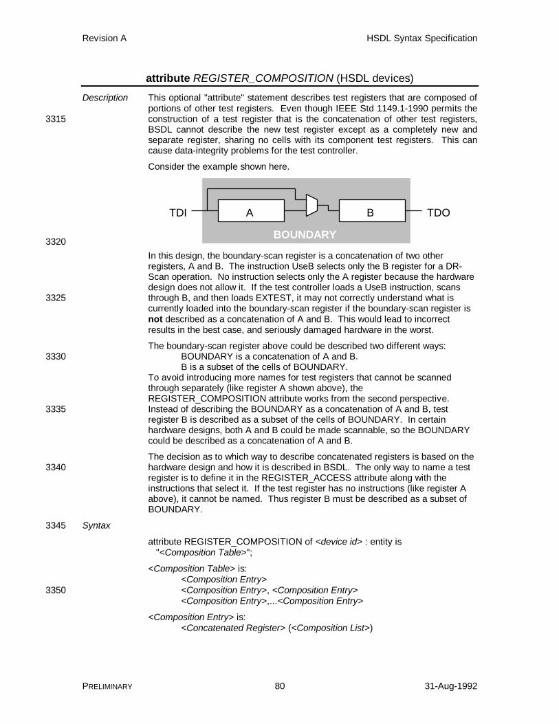
Revision A HSDL Syntax Specification
PRELIMINARY 80 31-Aug-1992
attribute REGISTER_COMPOSITION (HSDL devices)
Description This optional "attribute" statement describes test registers that are composed ofportions of other test registers. Even though IEEE Std 1149.1-1990 permits theconstruction of a test register that is the concatenation of other test registers,3315BSDL cannot describe the new test register except as a completely new andseparate register, sharing no cells with its component test registers. This cancause data-integrity problems for the test controller.
Consider the example shown here.
A BTDI TDO
BOUNDARY3320
In this design, the boundary-scan register is a concatenation of two otherregisters, A and B. The instruction UseB selects only the B register for a DR-Scan operation. No instruction selects only the A register because the hardwaredesign does not allow it. If the test controller loads a UseB instruction, scansthrough B, and then loads EXTEST, it may not correctly understand what is3325currently loaded into the boundary-scan register if the boundary-scan register isnot described as a concatenation of A and B. This would lead to incorrectresults in the best case, and seriously damaged hardware in the worst.
The boundary-scan register above could be described two different ways:BOUNDARY is a concatenation of A and B.3330B is a subset of the cells of BOUNDARY.
To avoid introducing more names for test registers that cannot be scannedthrough separately (like register A shown above), theREGISTER_COMPOSITION attribute works from the second perspective.Instead of describing the BOUNDARY as a concatenation of A and B, test3335register B is described as a subset of the cells of BOUNDARY. In certainhardware designs, both A and B could be made scannable, so the BOUNDARYcould be described as a concatenation of A and B.
The decision as to which way to describe concatenated registers is based on thehardware design and how it is described in BSDL. The only way to name a test3340register is to define it in the REGISTER_ACCESS attribute along with theinstructions that select it. If the test register has no instructions (like register Aabove), it cannot be named. Thus register B must be described as a subset ofBOUNDARY.
Syntax3345
attribute REGISTER_COMPOSITION of <device id> : entity is "<Composition Table>";
<Composition Table> is:<Composition Entry><Composition Entry>, <Composition Entry>3350<Composition Entry>,...<Composition Entry>
<Composition Entry> is:<Concatenated Register> (<Composition List>)
Revision A HSDL Syntax Specification
PRELIMINARY 81 31-Aug-1992
<Concatenated Register> is:<Register>3355
<Composition List> is:<Composition><Composition>, <Composition><Composition>,...<Composition>
<Composition> is:3360<Register><Register Cell><Register Cell Range>
<Register Cell> is:<Register> [ <Register Bit> ]3365
<Register Cell Range> is:<Register> [ <Register MSB>, <Register LSB> ]
<Register MSB> is:<Register Bit>
<Register LSB> is:3370<Register Bit>
<Register Bit> is:<VHDL Integer>
Parameters
<device id> A <VHDL identifier> giving the name of the3375entity.
<Composition Entry> Each composition entry describes how aconcatenated test register is composed of thecells of other test registers. The instructionregister may not be composed of other test3380registers, nor may any test register becomposed of parts of it.
<Concatenated Register> A <VHDL identifier> giving the name of a testregister previously declared in theREGISTER_ACCESS attribute. The predefined3385test registers BOUNDARY, BYPASS, andIDCODE can also be used. A test registercannot both be composed of and a part ofanother test register; i.e. A can be composed ofB or B can be composed of A, but not both.3390
<Composition List> The composition list defines which cells of whichtest registers are concatenated in what order toform the concatenated test register. Thecompositions are listed with the most significantcomposition as the first and the least significant3395composition as the last (MSB-to-LSB ordering).A specific cell (bit of a test register) may notoccur more than once in a composition(otherwise a circular test register is created).
<Composition> Each component of a concatenated register can3400be a complete test register, a one-cell subset of

Revision A HSDL Syntax Specification
PRELIMINARY 82 31-Aug-1992
a test register, or a subset of a test registerincluding a range of cells.
<Register Cell> A single cell of the test register is a componentof the concatenated register.3405
<Register Cell Range> Multiple cells of the test register form acomponent of the concatenated register.
<Register MSB> The register bit offset of the cell that will be themost significant bit of this component of theconcatenated register. This need not be the3410most significant bit of the register cell range. Ifthe register MSB is less than the register LSB,the significance of the cells is reversed in theconcatenated register.
<Register LSB> The register bit offset of the cell that will be the3415least significant bit of this component of theconcatenated register. This need not be theleast significant bit of the register cell range. Ifthe register MSB is less than the register LSB,the significance of the cells is reversed in the3420concatenated register.
<Register Bit> A <VHDL Integer> giving the cell offset in thetest register. 0 indicates the cell of the testregister closest to its TDO output.
Examples3425attribute REGISTER_ACCESS of My_IC : entity is "B[5] (UseB)";attribute REGISTER_COMPOSITION of My_IC : entity is "B (BOUNDARY[4,0])";
See Also attribute BUS_COMPOSITION (HSDL), attribute REGISTER_ACCESS (BSDL).3430
Revision A HSDL Syntax Specification
PRELIMINARY 83 31-Aug-1992
attribute REGISTER_DESCRIPTION (HSDL devices)
Description This optional "attribute" statement provides descriptions of the test registers in adevice. Any or all of the test registers defined in the device may have adescription. The description should provide enough information to the user sothat no additional documentation is necessary in order to understand the use and3435meaning of the test register.
Syntax
attribute REGISTER_DESCRIPTION of <device id> : constant is "<Register Descriptions>";
<Register Descriptions> is:3440<Register Description><Register Description>, <Register Description><Register Description>,...<Register Description>
<Register Description> is:<Register> ('<Description>')3445
Parameters
<device id> A <VHDL identifier> giving the name of theentity.
<Register> A <VHDL identifier> giving the name of apreviously defined test register. A test register3450may not be listed more than once.
<Description> A string providing a description of the use andmeaning of the test register. The string shouldbe descriptive enough to meet IEEE Std 1149.1-1990 Documentation Requirement 12.3.1.b.iv.3455
Examplesattribute REGISTER_DESCRIPTION of ttl74bct8374 : entity is "BCR ('The Boundary Control Register is a design-specific " & "test data register used to specify the test " & "function performed by the RUNT instruction.')";3460
See Also constant REGISTER_ACCESS (BSDL).
Revision A HSDL Syntax Specification
PRELIMINARY 84 31-Aug-1992
attribute REGISTER_RESET (HSDL devices)
Description This optional "attribute" statement indicates the patterns loaded into testregisters that are reset during Test-Logic-Reset state and at power-up. Itensures data integrity between the test controller and the UUT for user-defined3465test registers. An example of this is already defined in IEEE Std 1149.1-1990 forthe instruction register. The standard states that the instruction register alwaysloads the IDCODE instruction, or if not defined, the BYPASS instruction, onpower-up or Test-Logic-Reset.
Syntax3470
attribute REGISTER_RESET of <device id> : entity is "<Register Reset List>";
<Register Reset List> is:<Register Reset><Register Reset>, <Register Reset>3475<Register Reset>,...<Register Reset>
<Register Reset> is:<Register> ( <Reset Value> )
<Reset Value> is:<Pattern>3480<Symbol Name>
Parameters
<device id> A <VHDL identifier> giving the name of theentity.
<Register> A <VHDL identifier> giving the name of a3485previously defined test register. The devicemodifies the named test register on power-upand Test-Logic-Reset to the indicated value.Only the test register that are modified need tobe listed. A test register may not be listed more3490than once.
<Reset Value> A <VHDL integer> giving the value that isloaded into the test register on power-up andTest-Logic-Reset. The pattern or symbol nameshould not contain any don't-care bits.3495
Examplesattribute REGISTER_RESET of My_IC : entity is "INSTRUCTION (BYPASS)," & "BCR (PSA)";
See Also attribute REGISTER_ACCESS (BSDL).3500
Revision A HSDL Syntax Specification
PRELIMINARY 85 31-Aug-1992
attribute REGISTER_SYMBOLS (HSDL devices)
Description This optional "attribute" statement associates a symbol table with a test register.The TDI or TDI/TDO symbols named in the symbol table can then be shifted intothe specified test register, and the TDI/TDO or TDO symbols named in thesymbol table can be used as replacements for bit patterns that are captured and3505shifted out of the specified test register. The test register can be controlledsymbolically by using names instead of numbers. Usability is increased becausethe test engineer no longer needs to remember the bit patterns, just the names.
Syntax
attribute REGISTER_SYMBOLS of <device id> : entity is3510 "<Register Symbol List>";
<Register Symbol List> is:<Register Symbols><Register Symbols>, <Register Symbols><Register Symbols>,...<Register Symbols>3515
<Register Symbols> is:<Register> ( <Symbol Table Name> )
Parameters
<device id> A <VHDL identifier> giving the name of theentity.3520
<Register Symbol List> Each test register of the device may have onesymbol table associated with it. Neither all thetest registers nor all the symbol tables must belisted.
<Register> A <VHDL identifier> giving the name of a3525previously defined test register to attach asymbol table to.
<Symbol Table Name> A <VHDL identifier> giving the name of apreviously defined symbol table to attach to thetest register. A symbol table may be attached to3530any number of test registers.
Examplesattribute REGISTER_SYMBOLS of <device id> : entity is "BCR (BCR_Opcodes)";
See Also attribute BUS_SYMBOLS (HSDL), attribute SYMBOL_OF_TDI (HSDL), attribute3535SYMBOL_OF_TDO (HSDL), constant SYMBOL_TABLE (HSDL).
Revision A HSDL Syntax Specification
PRELIMINARY 86 31-Aug-1992
attribute SYMBOL_DEFAULT (HSDL)
Description This optional "attribute" statement classifies one of the symbols of a symboltable as the default symbol. The default symbol matches any value notspecifically assigned to any symbol in the symbol table. A default symbol is3540analogous to the BYPASS instruction. The BYPASS instruction is selected forany instruction pattern not specifically assigned to an instruction in theINSTRUCTION_OPCODE attribute.
Syntax
attribute SYMBOL_DEFAULT of <Symbol Table Name> : constant is3545 "<Symbol Name>";
Parameters
<Symbol Table Name> A <VHDL identifier> giving the name of apreviously defined symbol table.
<Symbol Name> A <VHDL identifier> giving the name of the3550symbol in the specified symbol table to beclassified as the default. This symbol is used bythe test controller to represent any value notspecifically assigned to a symbol in the symboltable.3555
Examplesattribute SYMBOL_DEFAULT of BCR_Opcodes : constant is "PSA";
See Also attribute INSTRUCTION_OPCODE (BSDL), constant SYMBOL_TABLE (HSDL).

Revision A HSDL Syntax Specification
PRELIMINARY 87 31-Aug-1992
attribute SYMBOL_DESCRIPTION (HSDL)
Description This optional "attribute" statement provides descriptions of the symbols in a3560symbol table. Any or all of the symbols defined in the symbol table may have adescription. The description should provide enough information to the user sothat no additional documentation is necessary in order to understand the use andmeaning of the symbol name.
Syntax3565
attribute SYMBOL_DESCRIPTION of <Symbol Table Name> : constant is "<Symbol Description Table>";
<Symbol Description Table> is:<Symbol Description Entry><Symbol Description Entry>, <Symbol Description Entry>3570<Symbol Description Entry>,...<Symbol Description Entry>
<Symbol Description Entry> is:<Symbol Name> ('<Symbol Description>')
Parameters
<Symbol Table Name> A <VHDL identifier> giving the name of a3575previously defined symbol table.
<Symbol Description Table> A string associating each symbol name in thesymbol table with a description. Each symbolname may be listed at most one time.
<Symbol Description Entry> Each entry provides a description for a symbol.3580
<Symbol Name> A <VHDL identifier> giving the name of asymbol previously defined in the named symboltable.
<Symbol Description> A string providing a description of the use andmeaning of the symbol.3585
Examplesattribute SYMBOL_DESCRIPTION of BCR_Opcodes : constant is "SAMTOG ('Samples device inputs on input bus; toggles " & "device outputs from output bus.')," & "PRPG ('Conducts 16-bit Pseudo-Random Pattern " &3590 "Generation using the contents of the input and " & "output buses of the Boundary-Scan register as " & "an initial value. The Q outputs of the device " & "are set to the value in the output bus. A new " & "pattern is generated on each TCK in " &3595 "Run-Test/Idle state.')," & "PSA ('Conducts 16-bit Parallel Signature Analysis " & "using the contents of the input and output " & "buses of the Boundary-Scan register as an " & "initial value. The Q outputs of the device " &3600 "are set to the value in the output bus. A " & "new checksum is generated on each TCK in " & "Run-Test/Idle state.')," & "PSAPRPG ('Simultaneous 8-bit PSA on the D inputs and " & "8-bit PRPG on the Q outputs.')";3605
See Also constant SYMBOL_TABLE (HSDL).
Revision A HSDL Syntax Specification
PRELIMINARY 88 31-Aug-1992
attribute SYMBOL_OF_TDI (HSDL)
Description This optional "attribute" statement categorizes certain symbol names in a symboltable as being valid only for shifting into TDI and applying to the system logic.Symbols listed in this attribute can be shifted in and applied to the UUT, but are3610never used as replacements for values that are captured and shifted out of theUUT.
TDI symbols have fewer restrictions than TDO symbols or TDI/TDO symbols.The values associated with two TDI symbols can be ambiguous and can even beidentical. For example, the SAMPLE and PRELOAD instructions have identical3615instruction bit patterns. The ambiguity is acceptable because the test controllerknows what bit pattern to shift in when given a TDI symbol name.
Syntax
attribute SYMBOL_OF_TDI of <Symbol Table Name> : constant is "<TDI Symbol List>";3620
<TDI Symbol List> is:<Symbol Name><Symbol Name>, <Symbol Name><Symbol Name>,...<Symbol Name>
Parameters3625
<Symbol Table Name> A <VHDL identifier> giving the name of apreviously defined symbol table.
<TDI Symbol List> A list of the symbol names that are only valid forshifting into TDI. Symbols not appearing in theSYMBOL_OF_TDI or SYMBOL_OF_TDO3630attributes are valid for both TDI and TDO. ATDI symbol name may not also appear in theSYMBOL_OF_TDO attribute. A symbol namemay not appear more than once in the list.
<Symbol Name> A <VHDL identifier> giving the name of a3635symbol in the specified symbol table to bedesignated as a TDI symbol.
Examplesattribute SYMBOL_OF_TDI of BIST_Symbols : constant is "TEST_BOUNDARY, TEST_CORE, FRY_DEVICE, BACKDRIVE_OUTPUTS";3640
See Also attribute SYMBOL_OF_TDO (HSDL), constant SYMBOL_TABLE (HSDL).
Revision A HSDL Syntax Specification
PRELIMINARY 89 31-Aug-1992
attribute SYMBOL_OF_TDO (HSDL)
Description This optional "attribute" statement categorizes certain symbol names in a symboltable as being valid only for represented bit patterns that are captured from thesystem logic and shifted out of TDO. Symbols listed in this attribute are used as3645replacements for values that are captured and shifted out of the UUT, but cannever be shifted in and applied to the system logic.
TDO symbols cannot be ambiguous or identical. Ambiguous values are valuescontaining don't-care bits such that two different values could represent thesame binary pattern. Ambiguity is unacceptable for TDO symbols because when3650a bit pattern is captured and shifted out, the test controller cannot determinewhich symbol name to use as a replacement for the bit pattern. Two differentsymbols both represent that value, so a unique replacement is not possible. Forthis reason, ambiguous TDO symbols are not allowed.
Syntax3655
attribute SYMBOL_OF_TDO of <Symbol Table Name> : constant is "<TDO Symbol List>";
<TDO Symbol List> is:<Symbol Name><Symbol Name>, <Symbol Name>3660<Symbol Name>,...<Symbol Name>
Parameters
<Symbol Table Name> A <VHDL identifier> giving the name of apreviously defined symbol table.
<TDO Symbol List> A list of the symbol names that are only valid for3665replacing bit patterns shifted out of TDO.Symbols not appearing in theSYMBOL_OF_TDI or SYMBOL_OF_TDOattributes are valid for both TDI and TDO. ATDO symbol name may not also appear in the3670SYMBOL_OF_TDI attribute. A symbol namemay not appear more than once in the list.
<Symbol Name> A <VHDL identifier> giving the name of asymbol in the specified symbol table to bedesignated as a TDO symbol.3675
Examplesattribute SYMBOL_OF_TDO of BIST_Symbols : constant is "BIST_WORKED, ALU_FAILURE, CU_FAILURE, TOTAL_FAILURE";
See Also attribute SYMBOL_OF_TDI (HSDL), constant SYMBOL_TABLE (HSDL).
Revision A HSDL Syntax Specification
PRELIMINARY 90 31-Aug-1992
constant DYNAMIC_PATH (HSDL modules)3680
Description This "constant" declaration is one of three that defines the scan paths of amodule. This statement defines a dynamic path, a scan path whose contentsare known at the time the HSDL file is written, but the placement of thosecontents in the scan path varies during the application of the test. Items in thedynamic path may be switched in and out of the scan path by controlling the3685connection of their TMS signals.
The dynamic path is useful for describing limited ad-hoc reconfiguration of thescan path in which only the TMS signals are modified. When an item in adynamic path is active, the TMS signal of the item is connected to the TMSsignal of the dynamic path as a whole. When inactive, the TMS signal of the3690item may be pulled high or low, placing the item in Test-Logic-Reset or Run-Test/Idle state, respectively.
The modification of TMS signals is outside the control of HSDL. The dynamicpath merely describes how the scan path reconfiguration of the UUT operates,not how to control it. This control must be performed elsewhere.3695
This statement cannot describe scan paths whose clocks are stopped "in place"and resynchronized with the TAP state diagram later. TAP signals cannot beswitched between scan paths with this statement. A dynamic path simply allowsitems to be placed into and removed from the scan path, and to describe whathappens to these items when they are removed from the scan path.3700
A dynamic path bears a strong resemblance to the case statement in manyprogramming languages. Each case statement value selects a differentconfiguration of the dynamic path.
Syntax
constant <Dynamic Path Name> : DYNAMIC_PATH :=3705 "<Dynamic Path Table>";
<Dynamic Path Table> is:<Dynamic Path Case>,...<Dynamic Path Case>
<Dynamic Path Case> is:<Dynamic Case Value> (<Dynamic Path List>)3710
<Dynamic Case Value> is:<VHDL Integer>
<Dynamic Path List> is:<Dynamic Path Configuration><Dynamic Path Configuration>, <Dynamic Path Configuration>3715<Dynamic Path Configuration>,...<Dynamic Path Configuration>
<Dynamic Path Configuration> is:<Static Path Entry> : <Dynamic Path State>
<Dynamic Path State> is:3720
<Dynamic Path Name>10
Revision A HSDL Syntax Specification
PRELIMINARY 91 31-Aug-1992
Parameters
<Dynamic Path Name> A <VHDL identifier> defining the name of the3725dynamic path. The name must be unique.
<Dynamic Path Table> This string describes the different configurationsallowed for the dynamic path. At least twocases must be present. If only one case isneeded, use a static path.3730
<Dynamic Path Case> Each dynamic path case defines a case valueand describes the configuration of the items inthe dynamic path when the dynamic path caseis active.
<Dynamic Case Value> A <VHDL Integer> that identifies the scan path3735configuration. Each dynamic case value mustbe unique within the DYNAMIC_PATH constant.At execution time, the test controller must bekept informed of the current case value for thedynamic path, so that it may conduct scans3740appropriately. Other software, hardware, etc. isneeded to ensure that the scan path in thehardware is actually changed to reflect thecurrent configuration.
<Dynamic Path List> The dynamic path list describes each item3745contained in the dynamic path and its test-mode-select state. The dynamic path list foreach dynamic case value must repeat the samedynamic path items. The state of everydynamic path item must be described in every3750case.
<Dynamic Path Configuration> Each configuration lists a dynamic path itemand indicates the state of the item by describingthe state of its TAP_SCAN_MODE port.
<Static Path Entry> Each dynamic path item can be any single item3755that can be contained in a static path: amember device or module, another pathdescribed in the module, or an external path in amember module.
<Dynamic Path State> The dynamic path state indicates the state of3760the TAP_SCAN_MODE port of the dynamicpath item. Using the name of the dynamic pathindicates that the dynamic path item isconnected to the TAP_SCAN_MODE port of thescan path. A 1 or 0 indicates that the3765TAP_SCAN_MODE port of the dynamic pathitem is either high or low, respectively, placingthe device in Test-Logic-Reset or Run-Test/Idle.
The dynamic path state keeps the test controllerdatabase consistent with the hardware state by3770informing the test controller of the current stateof the hardware. Thus the test controller canapply any REGISTER_RESET actions which

Revision A HSDL Syntax Specification
PRELIMINARY 92 31-Aug-1992
may be present in the devices of the dynamicpath.3775
Examplesconstant short : STATIC_PATH := "";constant c40switch : DYNAMIC_PATH := -- switch 'C40 out of path "0 (u29: 0, short: c40switch)," & -- 'C40 is in Run-Test/Idle "1 (u29: c40switch, short: 0)" ; -- 'C40 is in scan path3780
See Also attribute DYNAMIC_PATH_RESET (HSDL modules), attributeREGISTER_RESET (HSDL devices), attribute TAP_SCAN_MODE (BSDL),constant STATIC_PATH (HSDL modules).

Revision A HSDL Syntax Specification
PRELIMINARY 93 31-Aug-1992
constant EXTERNAL_PATH (HSDL modules)
Description This optional "constant" declaration is one of three that defines the scan paths of3785the module. This statement defines an external path, a scan path whosecontents may not be known at the time the HSDL file is written. An external pathoften represents a scannable backplane slot, which a scannable board can beinserted into at a later time. When describing the backplane, the slots aredescribed as external paths and thus any scannable board can be inserted at a3790later time. This scannable board is also described by an HSDL module file, andeither a higher-level HSDL module file or the test controller can be used toindicate which HSDL module is plugged into the slot.
External paths can also represent chip sockets, daughterboard connectors, testcontroller scan connectors, and so forth. Consider the board shown below.3795
This example board contains two backplane slots, one chip socket, and onecard-edge connector, all of which are scannable. No scannable devices ormodules are wired onto the board, only connectors for plugging in other thingslater. From the HSDL point of view, this module appears as shown here.3800
= external path
So the module is composed of four external paths and no members. Everyboard has at least one external path, the one containing the ports used by thetest controller to control the board. External paths "complete" the board scanpath, making it a circular path that includes the test controller.3805
The definition of an external path is such that, under the proper circumstances,either the test controller or a scannable module could be plugged into theexternal path. Conceptually, and given the proper hardware design, the test
Revision A HSDL Syntax Specification
PRELIMINARY 94 31-Aug-1992
controller could control the UUT from any external path on the board. Anexternal path contains one set of TAP signals, as described by the attributes3810TAP_SCAN_IN, TAP_SCAN_OUT, TAP_SCAN_CLOCK, TAP_SCAN_MODE,and TAP_SCAN_RESET. If a module has more than one set of TAP signals, allexternal paths must be defined to establish which path is associated with whichset of signals. If the module has only one set of TAP signals, no external pathdefinition is necessary, because the signals associated with the board scan path3815can be deduced. In this case, the board has only one external path, and itsdefinition is optional to simplify writing HSDL for a typical board.
Syntax
constant <External Path Name> : EXTERNAL_PATH := "<Port Name List>";3820
<Port Name List> is:<Port Name>, <Port Name>, <Port Name>, <Port Name><Port Name>, <Port Name>, <Port Name>, <Port Name>, <Port Name>
Parameters
<External Path Name> A <VHDL identifier> defining the name of the3825external path. This name must be unique. Bydefault, the external path is public.
<Port Name List> This string identifies the ports of the module thatcontrol or are controlled by the external path.Four or five port names may be listed: one3830TAP_SCAN_IN port, one TAP_SCAN_OUTport, one TAP_SCAN_CLOCK port, oneTAP_SCAN_MODE port, and optionally oneTAP_SCAN_RESET port. Each port namelisted must appear in one of the TAP_SCAN_IN3835/ TAP_SCAN_OUT / TAP_SCAN_CLOCK /TAP_SCAN_MODE / TAP_SCAN_RESETattribute statements. The port names may belisted in any order.
<Port Name> The port name listed must adhere to the3840following rules:
• A port listed in the TAP_SCAN_IN attributemust have mode "in".
• A port listed in the TAP_SCAN_OUTattribute must have mode "out".3845
• Ports listed in the TAP_SCAN_CLOCK,TAP_SCAN_MODE, andTAP_SCAN_RESET attributes must allhave mode in, out, or inout. If all aredefined as out, the external path is a pure3850unit-under-test connector. A module maybe connected to the external path, but a testcontroller may not. The external path isdesigned to control a scan path. If all aredefined as in, the external path is a pure test3855connector. A test controller may beconnected to the external path, but amodule may not. The external path is
Revision A HSDL Syntax Specification
PRELIMINARY 95 31-Aug-1992
designed to allow a test controller to controlthe module. If all are defined as inout, the3860external path may be either a test connectoror a unit-under-test connector, and either amodule or a test controller may beconnected.
Examples3865port (TDI, TCK, TMS, TRST: in bit; TDO: out bit); . . .attribute TAP_SCAN_IN of TDI : signal is true;3870attribute TAP_SCAN_OUT of TDO : signal is true;attribute TAP_SCAN_CLOCK of TCK : signal is (20.0e6, both);attribute TAP_SCAN_MODE of TMS : signal is true;attribute TAP_SCAN_RESET of TRST : signal is true; .3875 . .-- scannable connector J1constant j1 : EXTERNAL_PATH := "TDI, TDO, TCK, TMS, TRST";
See Also constant STATIC_PATH (HSDL modules), attribute TAP_SCAN_CLOCK3880(BSDL), attribute TAP_SCAN_IN (BSDL), attribute TAP_SCAN_MODE (BSDL),attribute TAP_SCAN_OUT (BSDL), attribute TAP_SCAN_RESET (BSDL), port(BSDL).

Revision A HSDL Syntax Specification
PRELIMINARY 96 31-Aug-1992
constant STATIC_PATH (HSDL modules)
Description This "constant" declaration is one of three that define the scan paths of a3885module. This statement defines a static path, a scan paths whose contents areknown and fixed at the time the HSDL file is written. A static path describes theusual interconnection of scannable devices and boards: the TDI/TDO pinsconnected serially, with the TMS, TCK, and TRST of all devices and boardswired together. The figure here shows a typical static path.3890
TDI TDO
TMS TCK TRST
TDI TDO
TMS TCK TRST
TDI TDO
TMS TCK TRST
TDITDO TCKTMS TRST
U1 U2 U3
J1
The static path depicted here has four items in it: three devices and oneexternal path. Since an external path describes the ports used to control it, thestatic path containing the external path completely describes the netlist of thetest bus. All connectivity information for TDI, TDO, TMS, TCK, and TRST3895signals can be derived.
Note that a static path appears circular when examining its TDI-to-TDOconnections. If all four entries in the example static path shown here wereexternal paths with suitable wiring, the choice of which external path representsthe TDI input to and TDO output from the module would be arbitrary. Any of the3900external paths could be chosen to plug the test controller into, in which case TDIbegins at that point and TDO ends at that point.
On simple boards consisting of one external path and a straightforward serialconnection between scannable devices and modules, only one path needs to bedefined: a static path simply listing all the scannable devices and modules in3905order. In this case, an external path containing the TAP signals for the moduleis implicit, and it is assumed to be the first entry in the static path.
Syntax
constant <Static Path Name> : STATIC_PATH := "<Static Path List>";3910
or
constant <Static Path Name> : STATIC_PATH := "";
<Static Path List> is:<Static Path Entry><Static Path Entry>, <Static Path Entry>3915<Static Path Entry>,...<Static Path Entry>
Revision A HSDL Syntax Specification
PRELIMINARY 97 31-Aug-1992
<Static Path Entry> is:<Member Name><Static Path Name><Dynamic Path Name>3920<Qualified External Path Name>
<Qualified External Path Name> is:<External Path Name><Member Name>.<External Path Name>
Parameters3925
<Static Path Name> A <VHDL identifier> defining the name of thestatic path. This name must be unique.
<Static Path List> The string that defines the composition andordering of the static path. The leftmost staticpath entry is closest to TDI; the rightmost static3930path entry is closest to TDO.
An empty static path list identifies a scan pathcontaining nothing; i.e. a "short" in the scanpath. This construct can be useful whenresolving external paths and when constructing3935dynamic paths.
<Static Path Entry> Each entry identifies a device, a static path, adynamic path, or an external path that isincluded in this static path. The TAP signals ofthe entry are implicitly connected to the TAP3940signals of the path. The left-to-right ordering ofentries indicates the TDI-to-TDO ordering of thescan path.
<Qualified External Path Name> The name of an external path. Theexternal path can be defined in this module or3945within a member of this module. External pathsappearing in a static path describe theconnections of the TAP ports of the module tothe TAP signals of the scan path.
Examples3950constant boardpath : STATIC_PATH := "J1, U1, U2, U3";
See Also attribute MEMBERS (HSDL modules), constant DYNAMIC_PATH (HSDLmodules), constant EXTERNAL_PATH (HSDL modules).
Revision A HSDL Syntax Specification
PRELIMINARY 98 31-Aug-1992
constant SYMBOL_TABLE (HSDL)
Description This optional "constant" declaration creates a symbol table. A symbol table3955defines symbol names and equates them to a list of values. The symbol namemay be used in place of any of the values after it is defined. Symbols increaseusability and readability. Instruction opcodes are similar to symbols, in that eachinstruction name represents any of the possible instruction bit patterns. Asymbol table can later be associated with any test register, any bus, or any port3960of the entity. Thus, symbolic names can be defined for a constant to be shiftedinto or shifted out of any element of the design.
Instruction names are examples of symbols intended for shifting into a deviceand applying to the device logic. In HSDL this type of symbol is called a TDIsymbol, because it is intended to be shifted into TDI. Symbols may also be3965defined that are intended to represent data captured by the device and shiftedout through TDO; this type of symbol is called a TDO symbol.
Why make a distinction between TDI and TDO symbols? IEEE Std 1149.1-1990contains the precedent. The data being shifted into the instruction register andapplied to the "test logic" has a different meaning from the data captured by the3970instruction register and shifted out of the device. The former is an instruction,the latter is status information. For the instruction register, TDI symbols areinstruction names and TDO symbols are status values. Other, design-specifictest registers may exhibit similar properties.
When a table is defined, the symbols are assumed to be both TDI and TDO3975symbols. They can be further defined as TDI or TDO symbols by listing them inthe SYMBOL_OF_TDI and SYMBOL_OF_TDO attributes.
Syntax
constant <Symbol Table Name> : SYMBOL_TABLE := "<Symbol Definitions>";3980
<Symbol Definitions> is:<Symbol Definition><Symbol Definition>, <Symbol Definition><Symbol Definition>,...<Symbol Definition>
<Symbol Definition> is:3985<Symbol Name> (<Symbol Values>)
<Symbol Values> is:<Symbol Value><Symbol Value>, <Symbol Value><Symbol Value>,...<Symbol Value>3990
<Symbol Value> is:<Pattern>
Parameters
<Symbol Table Name> A <VHDL identifier> defining the name of thesymbol table. This name must be unique.3995
<Symbol Definitions> A string listing the names of the symbols beingdefined and their associated values.
<Symbol Definition> Each symbol definition defines a symbol nameand associates values with it. A symbol namecan only be defined once per symbol table, but4000
Revision A HSDL Syntax Specification
PRELIMINARY 99 31-Aug-1992
may appear with different values in anothersymbol table.
<Symbol Name> A <VHDL identifier> defining the name of thesymbol. The symbol table creates a new scopeof names, so the symbol name must be unique4005within the symbol table but can be identical tothe other symbols names or even the names ofother elements of the entity. A well-knownexample is the BYPASS instruction, which is asymbol with the same name as a test register.4010
<Symbol Values> A list of values associated with the symbol.None of the values in the symbol table as awhole may be duplicated or ambiguous.Ambiguous values are values containing don't-care bits such that two different values could4015represent the same binary pattern.
<Symbol Value> A value associated with the symbol.
<Pattern> The pattern is a binary string that defines thesymbol value. X's are allowed in the pattern torepresent don't-care bits.4020
Examplesconstant BCR_Opcodes : SYMBOL_TABLE := "SAMTOG (00)," & "PRPG (01)," & "PSA (10)," &4025 "PSAPRPG (11)";
See Also attribute BOUNDARY_SYMBOLS (HSDL devices), attribute BUS_SYMBOLS(HSDL), attribute INSTRUCTION_OPCODE (BSDL), attributeREGISTER_SYMBOLS (HSDL devices), attribute SYMBOL_DEFAULT (HSDL),attribute SYMBOL_DESCRIPTION (HSDL), attribute SYMBOL_OF_TDI (HSDL),4030attribute SYMBOL_OF_TDO (HSDL).

Revision A HSDL Syntax Specification
PRELIMINARY 100 31-Aug-1992
use HSDL_device.all (HSDL devices)
Description This "use" statement identifies the VHDL package needed to define theattributes of an HSDL device. This package defines several extensions toBSDL, making possible the use of the new HSDL device features. The package4035contents are primarily ignored by an HSDL translator, but are necessary in aVHDL environment.
Syntax
use HSDL_device.all;
Parameters4040
None.
Examplesuse HSDL_device.all;
See Also use (BSDL), use HSDL_module.all (HSDL modules).

Revision A HSDL Syntax Specification
PRELIMINARY 101 31-Aug-1992
use HSDL_module.all (HSDL modules)4045
Description This "use" statement identifies the VHDL package needed to define theattributes of an HSDL module. This package defines several extensions toBSDL, making possible the definition of boards, boxes, multi-chip modules,subsystems, and systems. The package contents are primarily ignored by anHSDL translator, but are necessary in a VHDL environment.4050
Syntax
use HSDL_module.all;
Parameters
None.
Examples4055use HSDL_module.all;
See Also use (BSDL), use HSDL_device.all (HSDL devices).

Revision A HSDL Syntax Specification
PRELIMINARY 102 31-Aug-1992
B. HSDL Standard VHDL Package Definitions
These packages are used by HSDL to define the extra attributes and subtypes used in HSDL4060device and module entities. The package contents are not used by an HSDL translator, but arenecessary so that an HSDL description can be used successfully in a VHDL environment.
Note that only packages are needed for HSDL; no package bodies are required.
Consideration was given to having a third package containing the attributes and subtypes common to both device and moduleHSDL files, but the number of HSDL packages needed per file would then have been two, reducing ease of use.4065
B.1. HSDL_device Standard VHDL Packagepackage HSDL_device is
-- Device Description Declarations attribute DEVICE_DESCRIPTION : string;4070
-- Port Description Declarations attribute PORT_DESCRIPTION : string;
-- Instruction Register Declarations4075 attribute INSTRUCTION_NORMAL : string; attribute INSTRUCTION_TEST : string; attribute INSTRUCTION_DESCRIPTION : string;
-- Symbol Table Declarations4080 subtype SYMBOL_TABLE is string; attribute SYMBOL_OF_TDI : string; attribute SYMBOL_OF_TDO : string; attribute SYMBOL_DEFAULT : string; attribute SYMBOL_DESCRIPTION : string;4085
-- Register Information Declarations attribute REGISTER_COMPOSITION : string; attribute REGISTER_CAPTURE : string; attribute REGISTER_RESET : string;4090 attribute REGISTER_SYMBOLS : string; attribute REGISTER_DESCRIPTION : string;
-- Boundary Register Declarations attribute BOUNDARY_SYMBOLS : string;4095
-- Bus Declarations attribute BUS_COMPOSITION : string; attribute BUS_SYMBOLS : string; attribute BUS_DESCRIPTION : string;4100
-- Constraint Declarations attribute CONSTRAINTS : string; attribute CONSTRAINT_DESCRIPTION : string;
4105end HSDL_device ;
B.2. HSDL_module Standard VHDL Packagepackage HSDL_module is
-- Module Description Declarations4110 attribute MODULE_DESCRIPTION : string;
-- Port Description Declarations attribute PORT_DESCRIPTION : string;
4115-- Member Declarations attribute MEMBERS : string; attribute MEMBER_DESCRIPTION : string;

Revision A HSDL Syntax Specification
PRELIMINARY 103 31-Aug-1992
-- Symbol Table Declarations4120 subtype SYMBOL_TABLE is string; attribute SYMBOL_OF_TDI : string; attribute SYMBOL_OF_TDO : string; attribute SYMBOL_DEFAULT : string; attribute SYMBOL_DESCRIPTION : string;4125
-- Bus Declarations attribute BUS_COMPOSITION : string; attribute BUS_SYMBOLS : string; attribute BUS_DESCRIPTION : string;4130
-- Path Declarations subtype EXTERNAL_PATH is string; subtype DYNAMIC_PATH is string; attribute DYNAMIC_PATH_RESET : string;4135 subtype STATIC_PATH is string;
-- Connection Declarations attribute CONNECTIONS : string;
4140-- Constraint Declarations attribute CONSTRAINTS : string; attribute CONSTRAINT_DESCRIPTION : string;
end HSDL_module;4145