Embed Size (px)
Citation preview
Acta Biomaterialia 64 (2017) 1–14
Contents lists available at ScienceDirect
Acta Biomaterialia
journal homepage: www.elsevier .com/locate /actabiomat
Full length article
Hierarchical structure and compressive deformation mechanismsof bighorn sheep (Ovis canadensis) horn
https://doi.org/10.1016/j.actbio.2017.09.0431742-7061/� 2017 Acta Materialia Inc. Published by Elsevier Ltd. All rights reserved.
⇑ Corresponding authors at: Theoretical and Applied Mechanics Program, North-western University, Evanston, IL 60062, USA (H.D. Espinosa). Materials Science andEngineering Program, University of California, San Diego, La Jolla, CA 92037, USA(J. Mckittrick).
E-mail addresses: [email protected] (H.D. Espinosa), [email protected] (J. Mckittrick).
1 These authors contribute equally to the work.
Wei Huang a,1, Alireza Zaheri b,1, Jae-Young Jung a, Horacio D. Espinosa b,c,⇑, Joanna Mckittrick a,d,⇑aMaterials Science and Engineering Program, University of California, San Diego, La Jolla, CA 92037, USAb Theoretical and Applied Mechanics Program, Northwestern University, Evanston, IL 60062, USAcDepartment of Mechanical Engineering, Northwestern University, Evanston, IL 60062, USAdDepartment of Mechanical and Aerospace Engineering, University of California, San Diego, La Jolla, CA 92037, USA
a r t i c l e i n f o a b s t r a c t
Article history:Received 14 May 2017Received in revised form 21 September2017Accepted 29 September 2017Available online 30 September 2017
Keywords:Sheep hornKeratin cellsCompressive deformationImpact resistanceAnisotropy
Bighorn sheep (Ovis canadensis) rams hurl themselves at each other at speeds of �9 m/s (20 mph) to fightfor dominance and mating rights. This necessitates impact resistance and energy absorption mechanisms,which stem from material-structure components in horns. In this study, the material hierarchical struc-ture as well as correlations between the structure and mechanical properties are investigated. The majormicrostructural elements of horns are found as tubules and cell lamellae, which are oriented with (�30⁰)angle with respect to each other. The cell lamellae contain keratin cells, in the shape of pancakes, possess-ing an average thickness of �2 mm and diameter of �20–30 mm. The morphology of keratin cells revealsthe presence of keratin fibers and intermediate filaments with diameter of �200 nm and �12 nm, respec-tively, parallel to the cell surface. Quasi-static and high strain rate impact experiments, in different load-ing directions and hydration states, revealed a strong strain rate dependency for both dried and hydratedconditions. A strong anisotropy behavior was observed under impact for the dried state. The results showthat the radial direction is the most preferable impact orientation because of its superior energy absorp-tion. Detailed failure mechanisms under the aforementioned conditions are examined by bar impactrecovery experiments. Shear banding, buckling of cell lamellae, and delamination in longitudinal andtransverse direction were identified as the cause for strain softening under high strain rate impact.While collapse of tubules occurs in both quasi-static and impact tests, in radial and transverse directions,the former leads to more energy absorption and impact resistance.
Statement of Significance
Bighorn sheep (Ovis canadensis) horns show remarkable impact resistance and energy absorption whenundergoing high speed impact during the intraspecific fights. The present work illustrates the hierarchi-cal structure of bighorn sheep horn at different length scales and investigates the energy dissipationmechanisms under different strain rates, loading orientations and hydration states. These results demon-strate how horn dissipates large amounts of energy, thus provide a new path to fabricate energy absor-bent and crashworthiness engineering materials.
� 2017 Acta Materialia Inc. Published by Elsevier Ltd. All rights reserved.
1. Introduction mechanical efficiency, such as resistance to different loading
Natural structural materials possess variety of unique self-assembled hierarchical structures which result in remarkable
modes and ability to sustain extreme deformations with limitedselection of chemical constitutes along with optimized weight[1]. One example is the bighorn sheep (Ovis canadensis) horn,which can support an impact force as large as �3400 N [2]. Thevelocity of the intraspecific combat between two males can reach �9 m/s, deaccelerating in �2 ms with a deceleration estimatedas �450 g [3]. Hence, sheep horns experience high impact loadsduring combat with others animals and protection from predators[4]. At the same time, they need to absorb the impact energy tominimize its transmission to the skeletal frame of the animal.
2 W. Huang et al. / Acta Biomaterialia 64 (2017) 1–14
Based on the study of sheep collisions, an estimate of the strainrate experience by the horn material is of the order of 102–103
s�1 because of the extremely short impact time (�2 ms) [3], whichis much higher than previous reported result (�38 s�1) [5]. Thereason of the differences is in latter work, the initial impact speedwas set as 4.7 m/s, and the horn shape effects were considered aswell. The higher strain rates estimated in the present work arebased on the condition of �9 m/s for the initial impact velocity and �450 g for the acceleration reported by Courtney et.al [3]. Thisreveals the importance of high impact resistance in these materi-als. Horns are permanent structures which are made of an externalkeratin sheath covering a spongy bone core, and will not regener-ate or recover once fractured [6,7]. For the efficiency of horn infighting, they are expected to be: stiff and strong enough to resistthe impact force; tough enough to dissipate impact energy withoutfracture; light enough to be functional [2,8,9]. The overall shape ofthe horn, as well as the bone tissue inside the horn sheath, plays animportant role in protection of the sheep brain from impacts [5]. Inthis regard, understating the role of structural-material compo-nents on mechanical properties of horn keratin sheath providesinsight into utilization of these tissues during the lifetime of theanimal.
Keratin is selected through the evolutionary process for aplethora of animal tissues, such as hooves, claws, nails, hairs, woolsand scales [10,11]. Horn keratin is composed of a-helical crys-talline intermediate filaments (IFs, 7–10 nm in diameter), embed-ded in an amorphous non-helical keratin matrix [12–14]. Keratinin horns contains disulfide bonds as well as secondary bonds, suchas hydrogen bonds, to stabilize the amorphous matrix, by holdingtogether the non-crystalline polypeptides [15]. The hydrogenbonds are thought to be sensitive to hydration, which result inmechanical properties dependent on water content [16,17].Indeed, studies on the effect of hydration revealed a reduction onthe stiffness and strength of horn keratin [18–22]. The Young’smodulus of bighorn sheep horn has been reported to increase from0.63 to 2.2 GPa as the water content decreased from 34.5 to10.6 wt% water content [20]. However, the fracture toughness oforyx horn was found to increase from 2.2 MPa/m1/2 in dry condi-tion (0 wt% water content) to 4.5 MPa/m1/2 in fresh condition(20 wt% water content) [23]. This was argued as the result oflimited matrix yielding and plastic deformation in the fully drystate. The hydration sensitivity for many keratinous materials suchas human hair and nails [24,25], feathers [26] and hooves [27] has
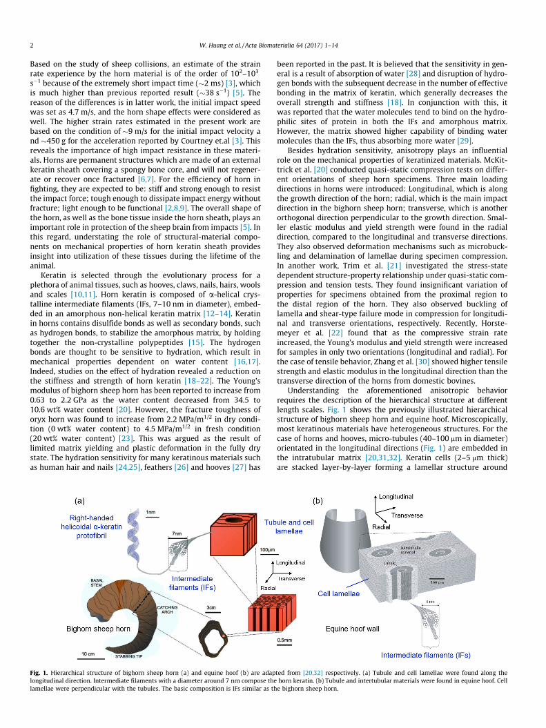
Fig. 1. Hierarchical structure of bighorn sheep horn (a) and equine hoof (b) are adaplongitudinal direction. Intermediate filaments with a diameter around 7 nm compose thelamellae were perpendicular with the tubules. The basic composition is IFs similar as th
been reported in the past. It is believed that the sensitivity in gen-eral is a result of absorption of water [28] and disruption of hydro-gen bonds with the subsequent decrease in the number of effectivebonding in the matrix of keratin, which generally decreases theoverall strength and stiffness [18]. In conjunction with this, itwas reported that the water molecules tend to bind on the hydro-philic sites of protein in both the IFs and amorphous matrix.However, the matrix showed higher capability of binding watermolecules than the IFs, thus absorbing more water [29].
Besides hydration sensitivity, anisotropy plays an influentialrole on the mechanical properties of keratinized materials. McKit-trick et al. [20] conducted quasi-static compression tests on differ-ent orientations of sheep horn specimens. Three main loadingdirections in horns were introduced: Longitudinal, which is alongthe growth direction of the horn; radial, which is the main impactdirection in the bighorn sheep horn; transverse, which is anotherorthogonal direction perpendicular to the growth direction. Smal-ler elastic modulus and yield strength were found in the radialdirection, compared to the longitudinal and transverse directions.They also observed deformation mechanisms such as microbuck-ling and delamination of lamellae during specimen compression.In another work, Trim et al. [21] investigated the stress-statedependent structure-property relationship under quasi-static com-pression and tension tests. They found insignificant variation ofproperties for specimens obtained from the proximal region tothe distal region of the horn. They also observed buckling oflamella and shear-type failure mode in compression for longitudi-nal and transverse orientations, respectively. Recently, Horste-meyer et al. [22] found that as the compressive strain rateincreased, the Young’s modulus and yield strength were increasedfor samples in only two orientations (longitudinal and radial). Forthe case of tensile behavior, Zhang et al. [30] showed higher tensilestrength and elastic modulus in the longitudinal direction than thetransverse direction of the horns from domestic bovines.
Understanding the aforementioned anisotropic behaviorrequires the description of the hierarchical structure at differentlength scales. Fig. 1 shows the previously illustrated hierarchicalstructure of bighorn sheep horn and equine hoof. Microscopically,most keratinous materials have heterogeneous structures. For thecase of horns and hooves, micro-tubules (40–100 mm in diameter)orientated in the longitudinal directions (Fig. 1) are embedded inthe intratubular matrix [20,31,32]. Keratin cells (2–5 mm thick)are stacked layer-by-layer forming a lamellar structure around
ted from [20,32] respectively. (a) Tubule and cell lamellae were found along thehorn keratin. (b) Tubule and intertubular materials were found in equine hoof. Celle bighorn sheep horn.
W. Huang et al. / Acta Biomaterialia 64 (2017) 1–14 3
the tubules as well as in the intertubular area. The arrangements ofthese lamellar cells vary in different tissues and species. Previously,Kasapi and Gosline [31] showed the complex orientation of the IFsaround the tubular cortex as well as in the intertubular area ofequine hooves. These along with the cell lamellae arrangementswere presented as the influential factors on mechanical propertiesof hooves. However, to the best of our knowledge the keratin celllamellae arrangements and IFs orientations in the bighorn sheephorn have not previously been identified. Moreover, previousstudies were mostly limited to low strain rates (�10�3 s�1)[20,21]. Even though some high-strain-rate mechanical propertieswere recently reported, deformation mechanisms as a function ofstrain rates were not sufficiently characterized. We believe this isdue to impedance mismatch between the employed bars used inthe Kolsky bar experimental setup and the horn samples. Thisled to a limited understanding of the energy absorption mecha-nisms [22]. Moreover, understanding of the mechanical behaviorwas limited by the lack of knowledge of the keratin microstructure.Thus, the present work aims to understand the following points: 1)The hierarchical structure of bighorn sheep horn, includingtubules, cell arrangement, intermediate filaments orientations; 2)The strain rate dependency, anisotropicity, and hydration effectson compressive properties; and 3) The compressive deformationmechanisms and their correlation with the hierarchical structure.
2. Experiments and methods
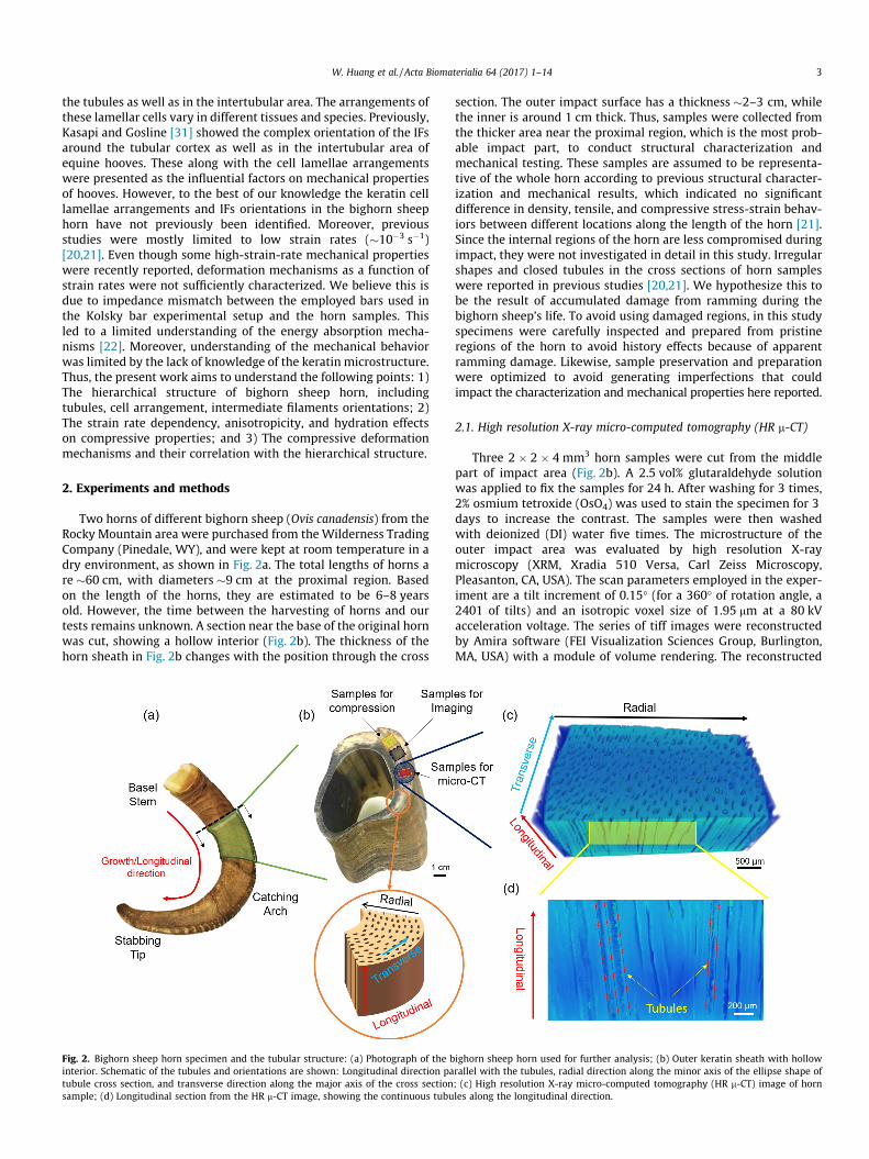
Two horns of different bighorn sheep (Ovis canadensis) from theRocky Mountain area were purchased from the Wilderness TradingCompany (Pinedale, WY), and were kept at room temperature in adry environment, as shown in Fig. 2a. The total lengths of horns are �60 cm, with diameters �9 cm at the proximal region. Basedon the length of the horns, they are estimated to be 6–8 yearsold. However, the time between the harvesting of horns and ourtests remains unknown. A section near the base of the original hornwas cut, showing a hollow interior (Fig. 2b). The thickness of thehorn sheath in Fig. 2b changes with the position through the cross
Fig. 2. Bighorn sheep horn specimen and the tubular structure: (a) Photograph of the binterior. Schematic of the tubules and orientations are shown: Longitudinal direction patubule cross section, and transverse direction along the major axis of the cross sectionsample; (d) Longitudinal section from the HR m-CT image, showing the continuous tubu
section. The outer impact surface has a thickness �2–3 cm, whilethe inner is around 1 cm thick. Thus, samples were collected fromthe thicker area near the proximal region, which is the most prob-able impact part, to conduct structural characterization andmechanical testing. These samples are assumed to be representa-tive of the whole horn according to previous structural character-ization and mechanical results, which indicated no significantdifference in density, tensile, and compressive stress-strain behav-iors between different locations along the length of the horn [21].Since the internal regions of the horn are less compromised duringimpact, they were not investigated in detail in this study. Irregularshapes and closed tubules in the cross sections of horn sampleswere reported in previous studies [20,21]. We hypothesize this tobe the result of accumulated damage from ramming during thebighorn sheep’s life. To avoid using damaged regions, in this studyspecimens were carefully inspected and prepared from pristineregions of the horn to avoid history effects because of apparentramming damage. Likewise, sample preservation and preparationwere optimized to avoid generating imperfections that couldimpact the characterization and mechanical properties here reported.
2.1. High resolution X-ray micro-computed tomography (HR m-CT)
Three 2 � 2 � 4 mm3 horn samples were cut from the middlepart of impact area (Fig. 2b). A 2.5 vol% glutaraldehyde solutionwas applied to fix the samples for 24 h. After washing for 3 times,2% osmium tetroxide (OsO4) was used to stain the specimen for 3days to increase the contrast. The samples were then washedwith deionized (DI) water five times. The microstructure of theouter impact area was evaluated by high resolution X-raymicroscopy (XRM, Xradia 510 Versa, Carl Zeiss Microscopy,Pleasanton, CA, USA). The scan parameters employed in the exper-iment are a tilt increment of 0.15� (for a 360� of rotation angle, a2401 of tilts) and an isotropic voxel size of 1.95 mm at a 80 kVacceleration voltage. The series of tiff images were reconstructedby Amira software (FEI Visualization Sciences Group, Burlington,MA, USA) with a module of volume rendering. The reconstructed
ighorn sheep horn used for further analysis; (b) Outer keratin sheath with hollowrallel with the tubules, radial direction along the minor axis of the ellipse shape of; (c) High resolution X-ray micro-computed tomography (HR m-CT) image of hornles along the longitudinal direction.
4 W. Huang et al. / Acta Biomaterialia 64 (2017) 1–14
three-dimensional rendering model was cropped and visualized toshow both transverse and longitudinal cross-sections. A colormap(from a minimum intensity with a dark blue to a maximumintensity with a red) was applied to distinguish the different ker-atin densities based on the acquired X-ray intensities.
2.2. Optical and scanning electron microscopy imaging
Samples (six samples in total, three from one horn and threefrom the second one) were cut into cubes with dimension 4 � 4� 4 mm3 and were located �5 mm from the impact surface asshowed in Fig. 2b. An ultramicrotome was used to make flat sur-faces of the cross and longitudinal sections in each block. Differen-tial interference contrast (DIC) optical microscopy images weretaken on the flat surface by a Keyence VHX 1000 (Keyence, Pala-tine, IL, USA). Thin slices (�1 mm thick, 6–9 slices for each cube)were cut by ultramicrotome (Leica EM UC6, Leica MicrosystemsInc., Buffalo Grove, IL, USA) and stained with toluidine blue, whichincreases the contrast of the keratin cells under the optical micro-scope. Optical microscopy images with different magnification(5�, 10�, 20�, 40�) were acquired. Porosities/pore sizes, celllamellae angle and cell sizes were quantified from the opticalimages. Half of the 6 cubes were immersed in a 2.5 vol% glutaralde-hyde solution overnight to fix the structure. A graded series ofethanol solutions (20%, 40%, 60%, 80%, 95%, and 100% vol% ethanol)were applied to further dehydrate the samples. Then the sampleswere freeze-fractured after immersion in liquid nitrogen in bothcross and longitudinal directions. Finally, a critical point dryer(Autosamdri-851, Tousimis, Rockville, MD, USA) was used to fur-ther remove the excess ethanol. Samples were sputter coated withiridium (Quorum Technologies Ltd., West Sussex, UK) to enhancethe sample electron conductivity before performing scanning elec-tron microscopy (SEM) imaging. An ultra-high resolution micro-scope (FEI, Hillsboro, OR, USA) was applied to conduct the SEMimaging.
2.3. Transmission electron microscopy imaging
Samples (four in total) were cut into small blocks with dimen-sion 2 � 1 � 1 mm3 from the similar areas as the SEM samples.Then the samples were immersed in a 2.5 vol% glutaraldehydesolution overnight. 2% OsO4 was applied to stain the horn speci-mens. After 24 h of staining at room temperature, the sampleswere washed with DI water five times. Then the samples were fur-ther stained with uranyl acetate for 1 day to obtain better contrast.The samples were washed with DI water for two times and thendehydrated with graded series of ethanol solutions (20%, 50%,70%, 90% and 100% vol% ethanol). After dehydration, samples wereembedded in Spurr’s low viscosity resin (Electron MicroscopySciences, Hatfield, PA, USA). An ultramicrotome (Leica EM UC6,Leica Microsystems Inc., Buffalo Grove, IL, USA) was used to prepare �80 nm thin sections to perform further imaging. Sectionson copper grids were post-stained by lead citrate solutions toenhance contrast. A FEI Tecnai 12 (Spirit) (80 kV) electron micro-scope (FEI, Hillsboro, Oregon, USA) was used to image the stainedsections with magnification from 1000� to 10,000� . The diame-ters of macrofibrils and orientations are estimated from TEMimages.
2.4. Compression tests
Due to the hollow design of horns, samples used for compres-sion tests were obtained from the proximal and central regionsof horn where it is the thickest (Fig. 2b). Samples were taken atpositions �10–20 cm from the proximal region of the horns. Thedimensions of the samples for quasi-static and dynamic testing
were 4 mm in all directions, which were prepared by use of hand-saw and powered-saw with diamond blade. Then, the sampleswere ground to obtain parallel faces. To examine the anisotropicbehavior of horn, samples were cut from three different orienta-tions: longitudinal, transversal and radial as shown in Fig. 2b.The samples were tested in ambient conditions as well ashydrated, in which they were immersed in DI water for 72 h. Inthe dried condition, the moisture content was around 10%,however, it is increased to �30 ± 0.7% in the hydrated condition(similar to the �35% reported in a previous study [20]). At leastthree samples for each direction, both in the dry and hydrationconditions, were tested and the final results were averaged. Forthe quasi-static uniaxial compression test, a universal testingmachine with a 30 kN load cell (Instron 3367 Dual Column TestingSystems, Instron, MA, USA) was used. The specimens were tested atstrain rates of 1 � 10�3 s�1, 1 � 10�1 s�1 and 5 � 10�1 s�1 (six sam-ples for each condition). In all experiments, the loading processwas continued until fracture occurred. Given that the natural strik-ing rates of sheep horns are �102–103 s�1, a split Hopkinson barsystemwas employed to test the samples dynamically. This systemhas been extensively used to determine the high strain ratemechanical properties of many materials from monolithic materi-als such as metals [33,34], ceramics [35] and polymers [36,37] tocomposite materials [38,39]. However, in the case of low impe-dance materials such as biological materials, proper modificationsin the split Hopkinson technique are required in order to obtainreliable and accurate results [40]. These mainly include strain rateconstancy and stress equilibrium at the interfaces of the sample[41,42]. The key to achieve the aforementioned criteria is the impe-dance mismatch ratio between bars and the sample [43]. To thisend, woven glass/epoxy composite (G-10) rods with a diameterof 12.7 mm were used for striking, incident, and transmission bars.Lower impedance of these bars in compare to the steel andaluminum with the same size (i.e. one fifth of steel and one halfof aluminum) leads to optimal strain rate constancy and stress uni-formity over the specimen length [41]. Moreover, the higher yieldstrength of G-10 is an advantage compared to polymeric bars,which provides higher load capacity (i.e., compressive stresses)to crush the specimens. To achieve a linear ramp loading, a poly-carbonate pulse shaper was used on the impact side of the incidentbar. In the present setup, a gas gun was used to fire the striker bar.A compressive pulse is generated on the incident bar, which travelstowards the specimen. A portion of the pulse is transmittedthrough the transmission bar by the specimen sandwichedbetween two bars and the remaining is reflected at the incidentbar-specimen interface. Finally, the stress pulses in the bars wererecorded by strain gages, amplified, and recorded in an oscillo-scope. The obtained stress-strain curves for all strain rates aregiven in Section 3. Due to the cost of experimentation and analysis,compared to the 6 samples tested in compression at low strainrates, three samples were selected as representative in each testingcondition. The average strain rate was �4000 s�1.
2.5. Hopkinson bar impact recovery tests and failure surface imaging
To further understand the interplay between horns microstruc-tural features such as tubules and their role in determining theoverall compressive deformation behavior, bar impact recoveryexperiments (i.e., experiments in which the sample deformationis limited to a specific strain level) were conducted. For thequasi-static tests, specimens were loaded to a specified strain leveland then unloaded with the same rate to the zero load level. Opti-cal images of different surfaces of the deformed specimens weretaken before and after the tests to track changes in microstructure.In the bar impact recovery tests, a stopper ring surrounding thesample was employed [44]. The function of the ring is to carry
W. Huang et al. / Acta Biomaterialia 64 (2017) 1–14 5
the load after the specimen achieves the desired axial strain. Thedesired strain was set around 25–30% since the softening behavioroccurs at that level observed from the obtained stress-strain curvesin Fig. 7. The stopper ring was made of G-10 with the same outerdiameter as the bars and an inner diameter large enough to avoidany radial confinement of the sample during axial compression.The faces of the ring were prepared to be as parallel as possibleto the bar end faces. Depending upon the desired strain level inthe recovered samples, the length of the ring was adjusted. Itshould be noted that the bar impact recovery results here reportedonly include the loading part. The recovery configuration herereported does not allow calculation of the unloaded part of thestress-strain curve. For this reason, the recovered part of the straincould only be obtained by comparison between the pristine andthe recovered sample lengths, as measured by a caliper. After test-ing, the specimens were coated with 15 nm Au/Pd and imaged in aSEM. It should take into account the fact that the recoveryexperiments in the present work, especially at high strain rates,were not reported previously. They were performed for under-standing energy dissipation mechanisms and revealing the role ofmicrostructure on deformation and failure behavior.
2.6. Statistical analysis
Detection of statistically significant differences (SSD) of theYoung’s modulus among different orientations were performedby a one-way analysis of variance (ANOVA) method. Tukey’s leastsignificant difference procedure was applied to conduct the multi-ple comparison tests with ANOVA. However, pairwise t-test wasemployed for SSD of Young’s modulus between dry and wet condi-tion in each direction as well as strain rate. The statistical signifi-cance level for both the ANOVA and t-test is assumed 0.05. Themechanical data were collected from multiple specimens in twoindependent horn samples.
3. Results and discussions
3.1. Hierarchical structure of horn
Fig. 2 shows the tubular structure of the bighorn sheep horn.Curved growth lines were observed from the proximal to distal
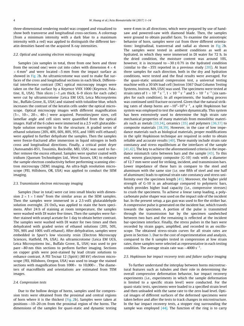
Fig. 3. Tubular and lamellar structure in the bighorn sheep horn: (a) Differential interfecross section and curved cell lamellae are observed; (b) Schematic diagram of the tubulacell lamellae. The angle between the cell lamella and tubule is �30�; (d) Scanning electrnoticed; (e) Cell lamellae in the longitudinal section shows �1–2 mm thickness of the la
regions of the horn (Fig. 2a). Previous results reported that thetubules (Fig. 2b) were found to be elliptically-shaped with majoraxis �80 mm, and minor axis �40 mm [20]. HR m-CT images showthe 3D tubular structure (Fig. 2c). Fig. 2d is a cross section alongthe longitudinal direction, showing that the parallel tubules arecontinuous along this direction. This is the first 3D study that ver-ifies the tubules are hollow and penetrate, in a short distance,through the horn tissue along the longitudinal growth direction.Since the tubules are produced by epidermal cells, their medullarycells develop at the tip of dermal papillae and subsequently extendthrough the whole horn [45]. Since the 3D reconstruction oftubules over the entire length of the horn is currently impractical,a sample with a 2 mm length in the base part was selected formicro-CT, which showed continuous tubules over that length. Fur-ther studies on tubule continuity in the centimeter length scalewill become possible as 3D reconstruction capabilities continueto improve.
Flat, (keratin) cells were identified forming the lamellar struc-ture in the horn. DIC optical microscopy images of the cross section(Fig. 3a) show the cell lamellae surrounding the tubules. Based onthe optical microscopy images, the average sizes of the elliptically-shaped cross section of the tubules were calculated. The size of themajor axis ranges between 40 – 80 mm with an average of 59 ± 13.8 mm. For the minor axis, the size is in the range of 10 – 40 mmwithan average of 24.6 ± 8.9 mm. Both major and minor axes dimen-sions are similar to what was previously reported [20]. The thick-ness of each keratin cell is �1–2 mm. Fig. 3b is a schematic of cellarrangements in a 3D horn model. From the DIC image of the lon-gitudinal section (Fig. 3c), it can be observed that there is an angle(�30�) between the cell lamellae and tubules, which implies thatthe lamellar cells are not exactly parallel to the tubules. SEMimages of the cross section (Fig. 3d) and the longitudinal section(Fig. 3e) further verify the laminated structure around the tubules,also confirming the thickness observed from optical microscopy.Keratin cell surfaces in Fig. 3f show that the cell diametersare �20–30 mm.
To get further understanding of the lamellar cell size and shape,optical microscopy images of toluidine blue stained thin sectionswere obtained. The 3D schematic and the optical microscopyimages are shown in Fig. 4a and c, respectively, revealed thatlamellae have an orientation of 30.16 ± 5.87� (averaged by 18 slices
rence contrast (DIC) optical microscopy image of the cross section. Elliptical tubuler and cell lamellar structure; (c) DIC image of the longitudinal section, showing theon microscopy image of the cross section. Cell lamellae stacking layer by layer wasmellae; (f) Keratin cells connect with each other forming the tubules.
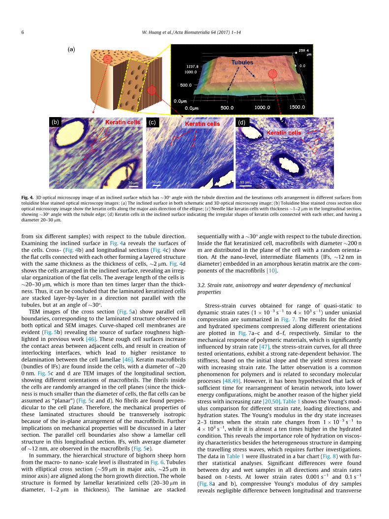
Fig. 4. 3D optical microscopy image of an inclined surface which has �30� angle with the tubule direction and the keratinous cells arrangement in different surfaces fromtoluidine blue stained optical microscopy images: (a) The inclined surface in both schematic and 3D optical microscopy image; (b) Toluidine blue stained cross section sliceoptical microscopy image show the keratin cells along the major axis direction of the ellipse; (c) Needle like keratin cells with thickness �1–2 mm in the longitudinal section,showing �30� angle with the tubule edge; (d) Keratin cells in the inclined surface indicating the irregular shapes of keratin cells connected with each other, and having adiameter 20–30 mm.
6 W. Huang et al. / Acta Biomaterialia 64 (2017) 1–14
from six different samples) with respect to the tubule direction.Examining the inclined surface in Fig. 4a reveals the surfaces ofthe cells. Cross- (Fig. 4b) and longitudinal sections (Fig. 4c) showthe flat cells connected with each other forming a layered structurewith the same thickness as the thickness of cells, �2 mm. Fig. 4dshows the cells arranged in the inclined surface, revealing an irreg-ular organization of the flat cells. The average length of the cells is�20–30 mm, which is more than ten times larger than the thick-ness. Thus, it can be concluded that the laminated keratinized cellsare stacked layer-by-layer in a direction not parallel with thetubules, but at an angle of �30�.
TEM images of the cross section (Fig. 5a) show parallel cellboundaries, corresponding to the laminated structure observed inboth optical and SEM images. Curve-shaped cell membranes areevident (Fig. 5b) revealing the source of surface roughness high-lighted in previous work [46]. These rough cell surfaces increasethe contact areas between adjacent cells, and result in creation ofinterlocking interfaces, which lead to higher resistance todelamination between the cell lamellae [46]. Keratin macrofibrils(bundles of IFs) are found inside the cells, with a diameter of �200 nm. Fig. 5c and d are TEM images of the longitudinal section,showing different orientations of macrofibrils. The fibrils insidethe cells are randomly arranged in the cell planes (since the thick-ness is much smaller than the diameter of cells, the flat cells can beassumed as ‘‘planar”) (Fig. 5c and d). No fibrils are found perpen-dicular to the cell plane. Therefore, the mechanical properties ofthese laminated structures should be transversely isotropicbecause of the in-plane arrangement of the macrofibrils. Furtherimplications on mechanical properties will be discussed in a latersection. The parallel cell boundaries also show a lamellar cellstructure in this longitudinal section. IFs, with average diameterof �12 nm, are observed in the macrofibrils (Fig. 5e).
In summary, the hierarchical structure of bighorn sheep hornfrom the macro- to nano- scale level is illustrated in Fig. 6. Tubuleswith elliptical cross section (�59 mm in major axis, �25 mm inminor axis) are aligned along the horn growth direction. The wholestructure is formed by lamellar keratinized cells (20–30 mm indiameter, 1–2 mm in thickness). The laminae are stacked
sequentially with a �30� angle with respect to the tubule direction.Inside the flat keratinized cell, macrofibrils with diameter �200 nm are distributed in the plane of the cell with a random orienta-tion. At the nano-level, intermediate filaments (IFs, �12 nm indiameter) embedded in an amorphous keratin matrix are the com-ponents of the macrofibrils [10].
3.2. Strain rate, anisotropy and water dependency of mechanicalproperties
Stress-strain curves obtained for range of quasi-static todynamic strain rates (1 � 10�3 s�1 to 4 � 103 s�1) under uniaxialcompression are summarized in Fig. 7. The results for the driedand hydrated specimens compressed along different orientationsare plotted in Fig. 7a–c and d–f, respectively. Similar to themechanical response of polymeric materials, which is significantlyinfluenced by strain rate [47], the stress-strain curves, for all threetested orientations, exhibit a strong rate-dependent behavior. Thestiffness, based on the initial slope and the yield stress increasewith increasing strain rate. The latter observation is a commonphenomenon for polymers and is related to secondary molecularprocesses [48,49]. However, it has been hypothesized that lack ofsufficient time for rearrangement of keratin network, into lowerenergy configurations, might be another reason of the higher yieldstress with increasing rate [20,50]. Table 1 shows the Young’s mod-ulus comparison for different strain rate, loading directions, andhydration states. The Young’s modulus in the dry state increases2–3 times when the strain rate changes from 1 � 10�3 s�1 to4 � 103 s�1, while it is almost a ten times higher in the hydratedcondition. This reveals the importance role of hydration on viscos-ity characteristics besides the heterogeneous structure in dampingthe travelling stress waves, which requires further investigations.The data in Table 1 were illustrated in a bar chart (Fig. 8) with fur-ther statistical analyses. Significant differences were foundbetween dry and wet samples in all directions and strain ratesbased on t-tests. At lower strain rates 0.001 s�1 and 0.1 s�1
(Fig. 8a and b), compressive Young’s modulus of dry samplesreveals negligible difference between longitudinal and transverse
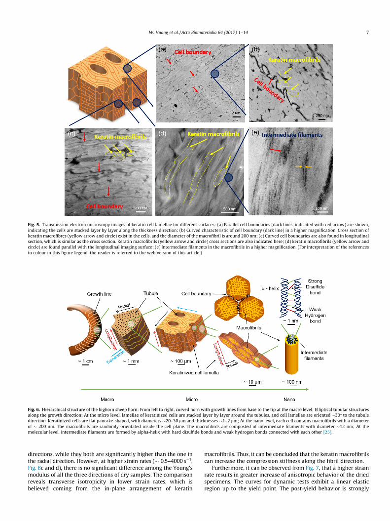
Fig. 5. Transmission electron microscopy images of keratin cell lamellae for different surfaces: (a) Parallel cell boundaries (dark lines, indicated with red arrow) are shown,indicating the cells are stacked layer by layer along the thickness direction; (b) Curved characteristic of cell boundary (dark line) in a higher magnification. Cross section ofkeratin macrofibres (yellow arrow and circle) exist in the cells, and the diameter of the macrofibril is around 200 nm; (c) Curved cell boundaries are also found in longitudinalsection, which is similar as the cross section. Keratin macrofibrils (yellow arrow and circle) cross sections are also indicated here; (d) keratin macrofibrils (yellow arrow andcircle) are found parallel with the longitudinal imaging surface; (e) Intermediate filaments in the macrofibrils in a higher magnification. (For interpretation of the referencesto colour in this figure legend, the reader is referred to the web version of this article.)
Fig. 6. Hierarchical structure of the bighorn sheep horn: From left to right, curved horn with growth lines from base to the tip at the macro level; Elliptical tubular structuresalong the growth direction; At the micro level, lamellae of keratinized cells are stacked layer by layer around the tubules, and cell lamellae are oriented �30� to the tubuledirection. Keratinized cells are flat pancake-shaped, with diameters �20–30 mm and thicknesses �1–2 mm; At the nano level, each cell contains macrofibrils with a diameterof � 200 nm. The macrofibrils are randomly orientated inside the cell plane. The macrofibrils are composted of intermediate filaments with diameter �12 nm; At themolecular level, intermediate filaments are formed by alpha-helix with hard disulfide bonds and weak hydrogen bonds connected with each other [25].
W. Huang et al. / Acta Biomaterialia 64 (2017) 1–14 7
directions, while they both are significantly higher than the one inthe radial direction. However, at higher strain rates (� 0.5–4000 s�1,Fig. 8c and d), there is no significant difference among the Young’smodulus of all the three directions of dry samples. The comparisonreveals transverse isotropicity in lower strain rates, which isbelieved coming from the in-plane arrangement of keratin
macrofibrils. Thus, it can be concluded that the keratin macrofibrilscan increase the compression stiffness along the fibril direction.
Furthermore, it can be observed from Fig. 7, that a higher strainrate results in greater increase of anisotropic behavior of the driedspecimens. The curves for dynamic tests exhibit a linear elasticregion up to the yield point. The post-yield behavior is strongly
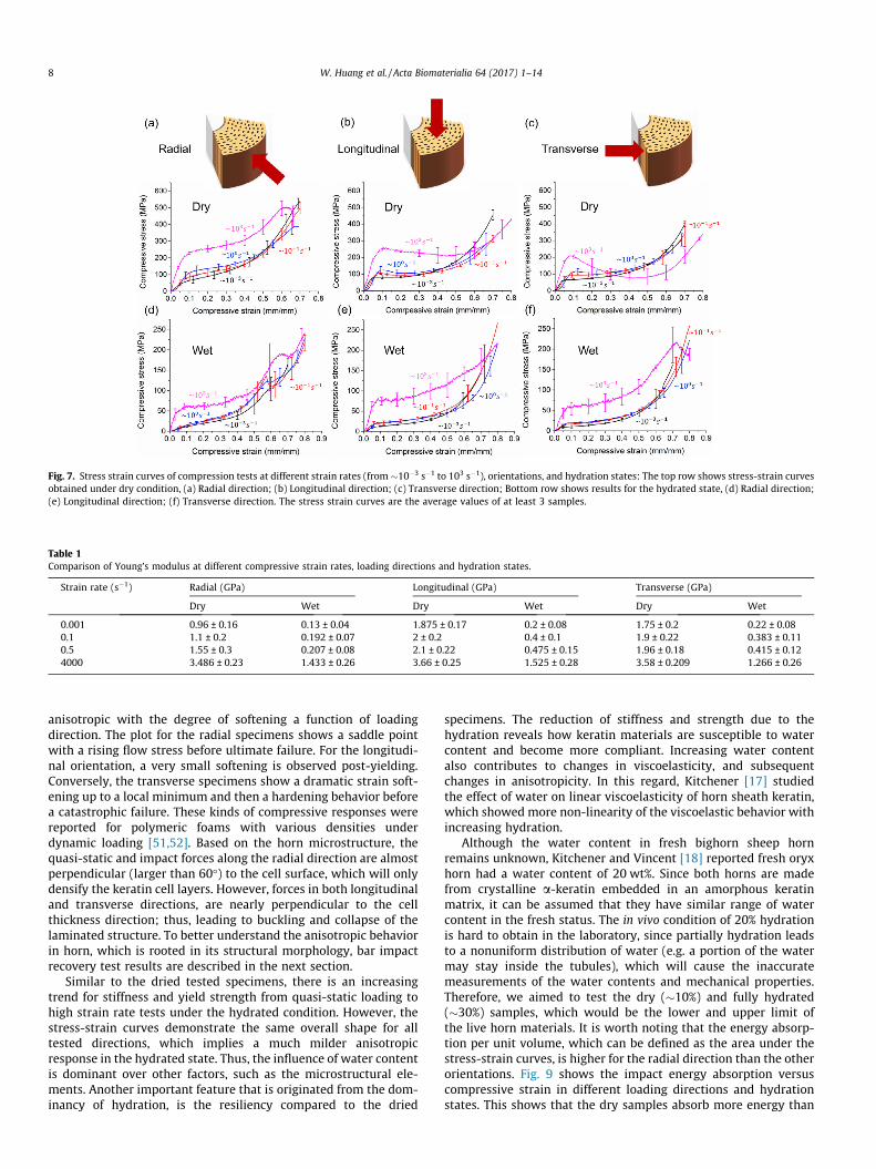
Fig. 7. Stress strain curves of compression tests at different strain rates (from�10�3 s�1 to 103 s�1), orientations, and hydration states: The top row shows stress-strain curvesobtained under dry condition, (a) Radial direction; (b) Longitudinal direction; (c) Transverse direction; Bottom row shows results for the hydrated state, (d) Radial direction;(e) Longitudinal direction; (f) Transverse direction. The stress strain curves are the average values of at least 3 samples.
Table 1Comparison of Young’s modulus at different compressive strain rates, loading directions and hydration states.
Strain rate (s�1) Radial (GPa) Longitudinal (GPa) Transverse (GPa)
Dry Wet Dry Wet Dry Wet
0.001 0.96 ± 0.16 0.13 ± 0.04 1.875 ± 0.17 0.2 ± 0.08 1.75 ± 0.2 0.22 ± 0.080.1 1.1 ± 0.2 0.192 ± 0.07 2 ± 0.2 0.4 ± 0.1 1.9 ± 0.22 0.383 ± 0.110.5 1.55 ± 0.3 0.207 ± 0.08 2.1 ± 0.22 0.475 ± 0.15 1.96 ± 0.18 0.415 ± 0.124000 3.486 ± 0.23 1.433 ± 0.26 3.66 ± 0.25 1.525 ± 0.28 3.58 ± 0.209 1.266 ± 0.26
8 W. Huang et al. / Acta Biomaterialia 64 (2017) 1–14
anisotropic with the degree of softening a function of loadingdirection. The plot for the radial specimens shows a saddle pointwith a rising flow stress before ultimate failure. For the longitudi-nal orientation, a very small softening is observed post-yielding.Conversely, the transverse specimens show a dramatic strain soft-ening up to a local minimum and then a hardening behavior beforea catastrophic failure. These kinds of compressive responses werereported for polymeric foams with various densities underdynamic loading [51,52]. Based on the horn microstructure, thequasi-static and impact forces along the radial direction are almostperpendicular (larger than 60�) to the cell surface, which will onlydensify the keratin cell layers. However, forces in both longitudinaland transverse directions, are nearly perpendicular to the cellthickness direction; thus, leading to buckling and collapse of thelaminated structure. To better understand the anisotropic behaviorin horn, which is rooted in its structural morphology, bar impactrecovery test results are described in the next section.
Similar to the dried tested specimens, there is an increasingtrend for stiffness and yield strength from quasi-static loading tohigh strain rate tests under the hydrated condition. However, thestress-strain curves demonstrate the same overall shape for alltested directions, which implies a much milder anisotropicresponse in the hydrated state. Thus, the influence of water contentis dominant over other factors, such as the microstructural ele-ments. Another important feature that is originated from the dom-inancy of hydration, is the resiliency compared to the dried
specimens. The reduction of stiffness and strength due to thehydration reveals how keratin materials are susceptible to watercontent and become more compliant. Increasing water contentalso contributes to changes in viscoelasticity, and subsequentchanges in anisotropicity. In this regard, Kitchener [17] studiedthe effect of water on linear viscoelasticity of horn sheath keratin,which showed more non-linearity of the viscoelastic behavior withincreasing hydration.
Although the water content in fresh bighorn sheep hornremains unknown, Kitchener and Vincent [18] reported fresh oryxhorn had a water content of 20 wt%. Since both horns are madefrom crystalline a-keratin embedded in an amorphous keratinmatrix, it can be assumed that they have similar range of watercontent in the fresh status. The in vivo condition of 20% hydrationis hard to obtain in the laboratory, since partially hydration leadsto a nonuniform distribution of water (e.g. a portion of the watermay stay inside the tubules), which will cause the inaccuratemeasurements of the water contents and mechanical properties.Therefore, we aimed to test the dry (�10%) and fully hydrated(�30%) samples, which would be the lower and upper limit ofthe live horn materials. It is worth noting that the energy absorp-tion per unit volume, which can be defined as the area under thestress-strain curves, is higher for the radial direction than the otherorientations. Fig. 9 shows the impact energy absorption versuscompressive strain in different loading directions and hydrationstates. This shows that the dry samples absorb more energy than
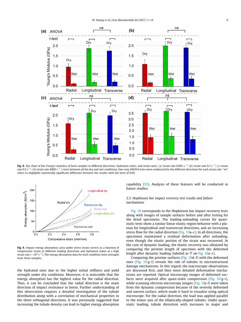
Fig. 8. Bar chart of the Young’s modulus of horn samples in different directions, hydration states, and strain rates: (a) strain rate 0.001 s�1; (b) strain rate 0.1 s�1; (c) strainrate 0.5 s�1; (d) strain rate 4000 s�1. t-tests between all the dry and wet conditions. One-way ANOVA tests were conducted for the different directions for each strain rate. ‘‘ns”refers to negligible statistically significant difference between the results with the level of 0.05.
Fig. 9. Impact energy absorption (area under stress-strain curves) as a function ofcompressive strain in different loading directions and hydration states at a highstrain rate (�103 s�1). The energy absorption data for each condition were averagedfrom three samples.
W. Huang et al. / Acta Biomaterialia 64 (2017) 1–14 9
the hydrated ones due to the higher initial stiffness and yieldstrength under dry conditions. Moreover, it is noticeable that theenergy absorption has the highest value for the radial direction.Thus, it can be concluded that the radial direction is the maindirection of impact resistance in horns. Further understanding ofthis observation requires a detailed investigation of the tubuledistribution along with a correlation of mechanical properties inthe three orthogonal directions. It was previously suggested thatincreasing the tubule density can lead to higher energy absorption
capability [53]. Analysis of these features will be conducted infuture studies.
3.3. Hopkinson bar impact recovery test results and failuremechanisms
Fig. 10 corresponds to the Hopkinson bar impact recovery testsalong with images of sample surfaces before and after testing forthe dried specimens. The loading-unloading curves for quasi-static tests show a similar linear elastic region behavior with a pla-teau for longitudinal and transversal directions, and an increasingstress flow for the radial direction (Fig. 10a–c). In all directions, thespecimens maintained a residual deformation after unloading,even though the elastic portion of the strain was recovered. Inthe case of dynamic loading, the elastic recovery was obtained bycomparing the pristine length of specimen with the deformedlength after dynamic loading (labeled as ‘f’ on Fig. 10a–c).
Comparing the pristine surfaces (Fig. 10d–f) with the deformedones (Fig. 10 g–l) reveals the role of tubules in microstructuraldamage mechanisms. In this regard, the macroscopic observationsare discussed first, and then more detailed deformation mecha-nisms are reported. Optical microscopy images of deformed sur-faces were acquired after quasi-static compression (Fig. 10 g–i),while scanning electron microscopy images (Fig. 10j–l) were takenfrom the dynamic compression because of the severely deformedand uneven surface, which made it hard to visualize using opticalmicroscope. For the radial direction, the load was applied parallelto the minor axis of the elliptically-shaped tubules. Under quasi-static loading, tubule distortion with increases in major and
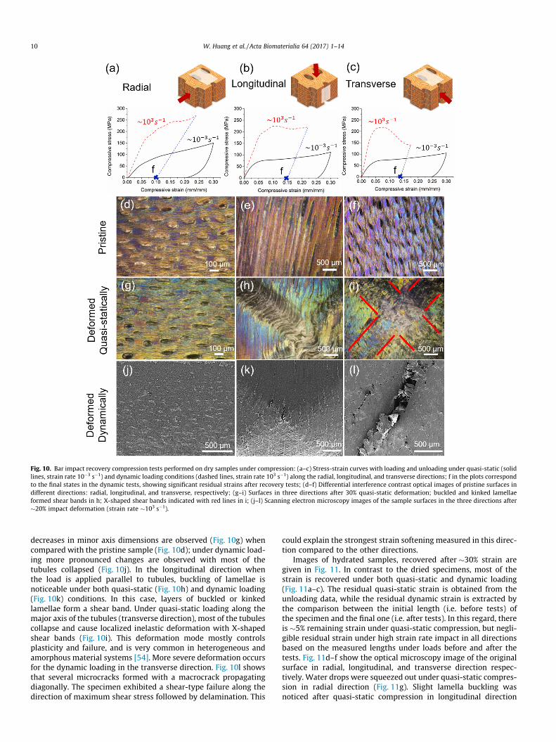
Fig. 10. Bar impact recovery compression tests performed on dry samples under compression: (a–c) Stress-strain curves with loading and unloading under quasi-static (solidlines, strain rate 10�3 s�1) and dynamic loading conditions (dashed lines, strain rate 103 s�1) along the radial, longitudinal, and transverse directions; f in the plots correspondto the final states in the dynamic tests, showing significant residual strains after recovery tests; (d–f) Differential interference contrast optical images of pristine surfaces indifferent directions: radial, longitudinal, and transverse, respectively; (g–i) Surfaces in three directions after 30% quasi-static deformation; buckled and kinked lamellaeformed shear bands in h; X-shaped shear bands indicated with red lines in i; (j–l) Scanning electron microscopy images of the sample surfaces in the three directions after�20% impact deformation (strain rate �103 s�1).
10 W. Huang et al. / Acta Biomaterialia 64 (2017) 1–14
decreases in minor axis dimensions are observed (Fig. 10g) whencompared with the pristine sample (Fig. 10d); under dynamic load-ing more pronounced changes are observed with most of thetubules collapsed (Fig. 10j). In the longitudinal direction whenthe load is applied parallel to tubules, buckling of lamellae isnoticeable under both quasi-static (Fig. 10h) and dynamic loading(Fig. 10k) conditions. In this case, layers of buckled or kinkedlamellae form a shear band. Under quasi-static loading along themajor axis of the tubules (transverse direction), most of the tubulescollapse and cause localized inelastic deformation with X-shapedshear bands (Fig. 10i). This deformation mode mostly controlsplasticity and failure, and is very common in heterogeneous andamorphous material systems [54]. More severe deformation occursfor the dynamic loading in the transverse direction. Fig. 10l showsthat several microcracks formed with a macrocrack propagatingdiagonally. The specimen exhibited a shear-type failure along thedirection of maximum shear stress followed by delamination. This
could explain the strongest strain softening measured in this direc-tion compared to the other directions.
Images of hydrated samples, recovered after �30% strain aregiven in Fig. 11. In contrast to the dried specimens, most of thestrain is recovered under both quasi-static and dynamic loading(Fig. 11a–c). The residual quasi-static strain is obtained from theunloading data, while the residual dynamic strain is extracted bythe comparison between the initial length (i.e. before tests) ofthe specimen and the final one (i.e. after tests). In this regard, thereis �5% remaining strain under quasi-static compression, but negli-gible residual strain under high strain rate impact in all directionsbased on the measured lengths under loads before and after thetests. Fig. 11d–f show the optical microscopy image of the originalsurface in radial, longitudinal, and transverse direction respec-tively. Water drops were squeezed out under quasi-static compres-sion in radial direction (Fig. 11g). Slight lamella buckling wasnoticed after quasi-static compression in longitudinal direction
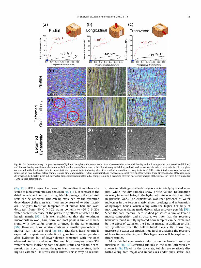
Fig. 11. Bar impact recovery compressive tests of hydrated samples under compression: (a–c) Stress-strain curves with loading and unloading under quasi-static (solid lines)and impact loading conditions, the latter with limited strain (�30% strain, dashed lines) along radial, longitudinal, and transverse directions, respectively; f in the plotscorrespond to the final states in both quasi-static and dynamic tests, indicating almost no residual strain after recovery tests; (d–f) Differential interference contrast opticalimages of original surfaces before compression in different directions: radial, longitudinal and transverse, respectively; (g–i) Surfaces in three directions after 30% quasi-staticdeformation. Red circles in (g) indicate water drops squeezed out after radial compression; (j–l) Scanning electron microscopy images of the surfaces in three directions after�30% impact deformation.
W. Huang et al. / Acta Biomaterialia 64 (2017) 1–14 11
(Fig. 11h). SEM images of surfaces in different directions when sub-jected to high strain rates are shown in Fig. 11j–l. In contrast to thedried tested specimens, no distinguishable damage in the hydratedtests can be observed. This can be explained by the hydrationdependence of the glass transition temperature of keratin materi-als. The glass transition temperature of human hair and wooldecreases from �80 �C (�10% water content) to �20 �C (�20%water content) because of the plasticizing effects of water on thekeratin matrix [55]. It is well established that the keratinousmicrofibrils in wool, hair, horn, and hoof possess similar dimen-sions, with low-sulfur proteins arranged in the same manner[56]. However, horn keratin contains a smaller proportion ofmatrix than hair and wool [56–58]. Therefore, horn keratin isexpected to experience a reduction in glass transition temperatureafter hydration but of lower degree compared with the onesobserved for hair and wool. The wet horn samples have �30%water content, indicating both the quasi-static and dynamic com-pression tests occur around the glass transition temperature, lead-ing to elastomer-like stress strain curves. This is why no residual
strains and distinguishable damage occur in totally hydrated sam-ples, while the dry samples show brittle failure. Deformationrecovery in animal hairs, in the hydrated state, was also identifiedin previous work. The explanation was that presence of watermolecules in the keratin matrix allows breakage and reformationof hydrogen bonds, which along with the higher flexibility ofmacromolecular chains made deformation recovery possible [59].Since the horn material here studied possesses a similar keratinmatrix composition and structure, we infer that the recoverybehaviors found in fully hydrated horn samples can be explainedby the effect of water on the keratin matrix. In addition to this,we hypothesize that the hollow tubules inside the horns mayincrease the water absorption, thus further assisting the recoveryof horn tissues after impact. This hypothesis will be explored infuture studies.
More detailed compressive deformation mechanisms are sum-marized in Fig. 12. Deformed tubules in the radial direction areshown in Fig. 12a–d. In the dry state, tubules are relatively dis-torted along both major and minor axes under quasi-static load
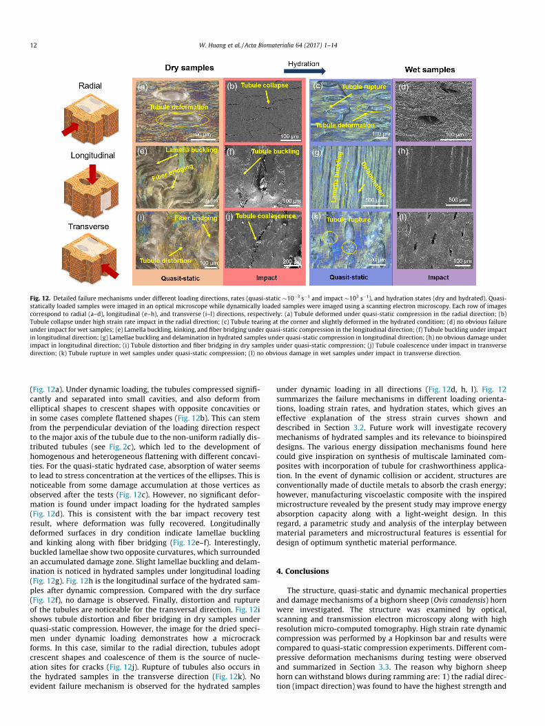
Fig. 12. Detailed failure mechanisms under different loading directions, rates (quasi-static �10�3 s�1 and impact �103 s�1), and hydration states (dry and hydrated). Quasi-statically loaded samples were imaged in an optical microscope while dynamically loaded samples were imaged using a scanning electron microscopy. Each row of imagescorrespond to radial (a–d), longitudinal (e–h), and transverse (i–l) directions, respectively: (a) Tubule deformed under quasi-static compression in the radial direction; (b)Tubule collapse under high strain rate impact in the radial direction; (c) Tubule tearing at the corner and slightly deformed in the hydrated condition; (d) no obvious failureunder impact for wet samples; (e) Lamella buckling, kinking, and fiber bridging under quasi-static compression in the longitudinal direction; (f) Tubule buckling under impactin longitudinal direction; (g) Lamellae buckling and delamination in hydrated samples under quasi-static compression in longitudinal direction; (h) no obvious damage underimpact in longitudinal direction; (i) Tubule distortion and fiber bridging in dry samples under quasi-static compression; (j) Tubule coalescence under impact in transversedirection; (k) Tubule rupture in wet samples under quasi-static compression; (l) no obvious damage in wet samples under impact in transverse direction.
12 W. Huang et al. / Acta Biomaterialia 64 (2017) 1–14
(Fig. 12a). Under dynamic loading, the tubules compressed signifi-cantly and separated into small cavities, and also deform fromelliptical shapes to crescent shapes with opposite concavities orin some cases complete flattened shapes (Fig. 12b). This can stemfrom the perpendicular deviation of the loading direction respectto the major axis of the tubule due to the non-uniform radially dis-tributed tubules (see Fig. 2c), which led to the development ofhomogenous and heterogeneous flattening with different concavi-ties. For the quasi-static hydrated case, absorption of water seemsto lead to stress concentration at the vertices of the ellipses. This isnoticeable from some damage accumulation at those vertices asobserved after the tests (Fig. 12c). However, no significant defor-mation is found under impact loading for the hydrated samples(Fig. 12d). This is consistent with the bar impact recovery testresult, where deformation was fully recovered. Longitudinallydeformed surfaces in dry condition indicate lamellae bucklingand kinking along with fiber bridging (Fig. 12e–f). Interestingly,buckled lamellae show two opposite curvatures, which surroundedan accumulated damage zone. Slight lamellae buckling and delam-ination is noticed in hydrated samples under longitudinal loading(Fig. 12g). Fig. 12h is the longitudinal surface of the hydrated sam-ples after dynamic compression. Compared with the dry surface(Fig. 12f), no damage is observed. Finally, distortion and ruptureof the tubules are noticeable for the transversal direction. Fig. 12ishows tubule distortion and fiber bridging in dry samples underquasi-static compression. However, the image for the dried speci-men under dynamic loading demonstrates how a microcrackforms. In this case, similar to the radial direction, tubules adoptcrescent shapes and coalescence of them is the source of nucle-ation sites for cracks (Fig. 12j). Rupture of tubules also occurs inthe hydrated samples in the transverse direction (Fig. 12k). Noevident failure mechanism is observed for the hydrated samples
under dynamic loading in all directions (Fig. 12d, h, l). Fig. 12summarizes the failure mechanisms in different loading orienta-tions, loading strain rates, and hydration states, which gives aneffective explanation of the stress strain curves shown anddescribed in Section 3.2. Future work will investigate recoverymechanisms of hydrated samples and its relevance to bioinspireddesigns. The various energy dissipation mechanisms found herecould give inspiration on synthesis of multiscale laminated com-posites with incorporation of tubule for crashworthiness applica-tion. In the event of dynamic collision or accident, structures areconventionally made of ductile metals to absorb the crash energy;however, manufacturing viscoelastic composite with the inspiredmicrostructure revealed by the present study may improve energyabsorption capacity along with a light-weight design. In thisregard, a parametric study and analysis of the interplay betweenmaterial parameters and microstructural features is essential fordesign of optimum synthetic material performance.
4. Conclusions
The structure, quasi-static and dynamic mechanical propertiesand damage mechanisms of a bighorn sheep (Ovis canadensis) hornwere investigated. The structure was examined by optical,scanning and transmission electron microscopy along with highresolution micro-computed tomography. High strain rate dynamiccompression was performed by a Hopkinson bar and results werecompared to quasi-static compression experiments. Different com-pressive deformation mechanisms during testing were observedand summarized in Section 3.3. The reason why bighorn sheephorn can withstand blows during ramming are: 1) the radial direc-tion (impact direction) was found to have the highest strength and
W. Huang et al. / Acta Biomaterialia 64 (2017) 1–14 13
energy absorption in both dry and hydrated states; 2) The defor-mation recovery exhibited by horns in the hydrated states appearto confirm them the ability to withstand multiple blows withoutfracture during ramming. As a result, the main conclusions in pre-sent work are:
� The horn microstructure consists of tubules as well as a lami-nated structure formed by keratinous cells. The former arelocated along the longitudinal direction with an elliptically-shaped cross section (major axis �59 mm, minor axis �25 mm),confirmed by high resolution X-ray computed tomography.Laminated keratinous cells surround the tubules. The dimen-sion of the keratin cells are 20–30 mm in diameter and 1–2 mmin thickness. There is a �30.16 ± 5.87� angle between cell lamel-lae and tubules.
� Keratin macrofibrils with diameter �200 nm were found ran-domly oriented in the keratinized cell planes and parallel withthe cell surfaces. The fibrils are bundles of intermediate fila-ments with dimension �12 nm in diameter. These in-planearrangements of macrofirbils, reported here for the first time,explain the transverse isotropic behavior identified throughcompression tests.
� Stress strain curves of quasi-static and dynamic tests indicatedhigher energy absorption and impact resistance in the radialdirection, which is the impact direction of the horn. InitialYoung’s modulus of dry samples in longitudinal and transversedirections are significant higher than in the radial direction atlower strain rates (0.001 and 0.1 s�1), showing transverse iso-tropy due to the laminated structure around the tubules.
� Damage at various strain rates was examined by conductingHopkinson bar impact recovery tests. More material damageis observed with increasing strain rate in the dry condition.Pre- and post-test microscopy imaging reveals various inelasticdeformation mechanisms: kink bands, lamella buckling, tubulecollapse, and microcracking, which highlighted the role ofstructural elements such as tubules and lamellae in relation toloading. Tubule collapse in the radial direction leads to signifi-cant energy absorption, while lamella buckling and shear bandformation in the longitudinal and transverse directions causecatastrophic failure of material with less energy absorption.
� Dramatic differences in behavior were observed as a function ofsample hydration. Under the dry condition, the samples exhib-ited a strong anisotropic behavior as well as strain rate depen-dency. Specimen hydration leads to a more isotropic behavior,while still rate dependent. The hydrated specimens recovertheir initial length under dynamic loading at strains as high as20–30%. This can be explained by the decrease of the glass tran-sition temperature of hydrate samples, thus leading to a strongviscoelastic behavior under compression. This feature isremarkable because it shows that hydrated horn material canabsorb significant amounts of energy without damage.
The findings of this study demonstrated how horn dissipateslarge amount of energy during deformation in different orienta-tions and hydration states. Moreover, the revealed hierarchicalorganization of horn constituents such as layers of keratin cellsalong with incorporation of tubules can serve as bio-inspirationfor the design of synthetic composites. Compression tests in dryconditions demonstrate the role of tubules in the deformationmechanisms as well as their role in determining the preferableimpact orientation. Therefore, the results of this paper hint at apath to tune energy-absorbent engineering materials thatincorporate tubular structures as a function of impact direction.Moreover, the water-assisted recoverability of keratin underhigh-energy impact provides inspiration towards design of recov-erable energy-absorbent materials.
Acknowledgements
This work is supported by a Multi-University Research Initiative(MURI) through the Air Force Office of Scientific Research of theUnited States (AFOSR-FA9550-15-1-0009) and a National ScienceFoundation Biomaterials Program Grant 1507978. We appreciateEric Bushong and Mason Mackey at National Center for Microscopyand Imaging Research (NCMIR), Timo Meerloo and Ying Jones atElectron Microscopy Facility at UC San Diego for providing the helpwith micro-computed tomography and TEM sample preparationand imaging. We thank Ryan Anderson of the Nano3 Laboratoryof CalIt2 for helping with the SEM and optical microscopy and Prof.Marc A. Meyers from UC San Diego for his kind and enthusiasticsupport of this project. This work was performed in part at theSan Diego Nanotechnology Infrastructure (SDNI) of UCSD, a mem-ber of the National Nanotechnology Coordinated Infrastructure,which is supported by the National Science Foundation (GrantECCS-1542148).
References
[1] U.G.K. Wegst, M.F. Ashby, The mechanical efficiency of natural materials, Phil.Mag. 84 (2004) 2167–2181.
[2] A. Kitchener, An analysis of the forces of fighting of the blackbuck (antilope-cervicapra) and the bighorn sheep (Ovis-Canadensis) and the mechanicaldesign of the horns of bovids, J. Zool. 214 (1988) 1–20.
[3] Courtney M, Courtney A, ‘‘Sheep Collisions: the Good, the Bad, and the TBI,”arXiv preprint arXiv:0711.3804, (2007).
[4] V. Geist, The evolution of horn-like organs, Behaviour 27 (1966) 175–214.[5] A. Drake, T.L.H. Donahue, M. Stansloski, K. Fox, B.B. Wheatley, S.W. Donahue,
Horn and horn core trabecular bone of bighorn sheep rams absorbs impactenergy and reduces brain cavity accelerations during high impact ramming ofthe skull, Acta Biomater. 44 (2016) 41–50.
[6] Domenici P, Blake, R.W., ‘‘Biomechanics in Animal Behavior,” (BIOS Scientific,2000).
[7] Rayner JMV, Wootton RJ, Society for Experimental Biology (Great Britain),Biomechanics in evolution. Society for Experimental Biology seminar series(Cambridge University Press, Cambridge; New York, 1991), pp. xiv, 273 pages.
[8] A. Kitchener, The effect of behavior and body-weight on the mechanical designof horns, J. Zool. 205 (1985) 191–203.
[9] Blake RW, Domenici P, Biomechanics in animal behaviour. Experimentalbiology reviews (BIOS Scientific, Oxford, 2000), pp. xv, 344 pages.
[10] B. Wang, W. Yang, J. McKittrick, M.A. Meyers, Keratin: Structure, mechanicalproperties, occurrence in biological organisms, and efforts at bioinspiration,Prog. Mater Sci. 76 (2016) 229–318.
[11] J. McKittrick, P.Y. Chen, S.G. Bodde, W. Yang, E.E. Novitskaya, M.A. Meyers, Thestructure, functions, and mechanical properties of keratin, JOM 64 (2012) 449–468.
[12] R. Fraser, T. MacRae, A. Miller, The coiled-coil model of a-keratin structure, J.Mol. Biol. 10 (1964) 147IN128–156IN129.
[13] R. Marshall, D.-G. Orwin, J. Gillespie, Structure and biochemistry ofmammalian hard keratin, Electron. Microscopy Rev. 4 (1991) 47–83.
[14] R. Fraser, T. MacRae, E. Suzuki, Structure of the a-keratin microfibril, J. Mol.Biol. 108 (1976) 435–452.
[15] A.N. Parbhu, W.G. Bryson, R. Lal, Disulfide bonds in the outer layer of keratinfibers confer higher mechanical rigidity: correlative nano-indentation andelasticity measurement with an AFM, Biochemistry 38 (1999) 11755–11761.
[16] D.S. Fudge, K.H. Gardner, V.T. Forsyth, C. Riekel, J.M. Gosline, The mechanicalproperties of hydrated intermediate filaments: insights from hagfish slimethreads, Biophys. J . 85 (2003) 2015–2027.
[17] A. Kitchener, Effect of water on the linear viscoelasticity of horn sheath keratin,J. Mater. Sci. Lett. 6 (1987) 321–322.
[18] A. Kitchener, J.F.V. Vincent, Composite theory and the effect of water on thestiffness of horn keratin, J. Mater. Sci. 22 (1987) 1385–1389.
[19] B.W. Li, H.P. Zhao, X.Q. Feng, W.W. Guo, S.C. Shan, Experimental study on themechanical properties of the horn sheaths from cattle, J. Exp. Biol. 213 (2010)479–486.
[20] L. Tombolato, E.E. Novitskaya, P.Y. Chen, F.A. Sheppard, J. McKittrick,Microstructure, elastic properties and deformation mechanisms of hornkeratin, Acta Biomater. 6 (2010) 319–330.
[21] M.W. Trim, M.F. Horstemeyer, H. Rhee, H. El Kadiri, L.N. Williams, J. Liao, K.B.Walters, J. McKittrick, S.J. Park, The effects of water and microstructure on themechanical properties of bighorn sheep (Ovis canadensis) horn keratin, ActaBiomater. 7 (2011) 1228–1240.
[22] K. Johnson, M. Trim, D. Francis, W. Whittington, J. Miller, C. Bennett, M.Horstemeyer, Moisture, anisotropy, stress state, and strain rate effects onbighorn sheep horn keratin mechanical properties, Acta Biomater. 48 (2017)300–308.
[23] A. Kitchener, Fracture-toughness of horns and a reinterpretation of the horningbehavior of bovids, J. Zool. 213 (1987) 621–639.
14 W. Huang et al. / Acta Biomaterialia 64 (2017) 1–14
[24] L. Farran, A.R. Ennos, S.J. Eichhorn, The effect of humidity on the fractureproperties of human fingernails, J. Exp. Biol. 211 (2008) 3677–3681.
[25] Feughelman M, Mechanical properties and structure of alpha-keratin fibres:wool, human hair and related fibres. (UNSW press, 1997).
[26] A.M. Taylor, R.H.C. Bonser, J.W. Farrent, The influence of hydration on thetensile and compressive properties of avian keratinous tissues, J. Mater. Sci. 39(2004) 939–942.
[27] J.E.A. Bertram, J.M. Gosline, Functional design of horse hoof keratin – themodulation of mechanical-properties through hydration effects, J. Exp. Biol.130 (1987) 121–136.
[28] M. Feughelman, M. Robinson, The relationship between some mechanicalproperties of single wool fibers and relative humidity, Textile Res. J. 37 (1967)441–446.
[29] M. Breuer, The binding of small molecules to hair-I: the hydration of hair andthe effect of water on the mechanical properties of hair, J. Soc. Cosmet. Chem.23 (1972).
[30] Q.B. Zhang, C. Li, Y.T. Pan, G.H. Shan, P. Cao, J. He, Z.S. Lin, N.J. Ao, Y.X. Huang,Microstructure and mechanical properties of horns derived from threedomestic bovines, Mater. Sci. Eng. C 33 (2013) 5036–5043.
[31] M.A. Kasapi, J.M. Gosline, Design complexity and fracture control in the equinehoof wall, J. Exp. Biol. 200 (1997) 1639–1659.
[32] M.A. Kasapi, J.M. Gosline, Micromechanics of the equine hoof wall: optimizingcrack control and material stiffness through modulation of the properties ofkeratin, J. Exp. Biol. 202 (1999) 377–391.
[33] G.T. Gray III, Classic split-Hopkinson pressure bar testing, in: ASM Handbook,Mechanical Testing and Evaluation, 2000, pp. 462–476.
[34] Meyers M, Shock waves and high-strain-rate phenomena in metals: conceptsand applications. (Springer Science & Business Media, 2012).
[35] W.N. Chen, G. Ravichandran, Dynamic compressive failure of a glass ceramicunder lateral confinement, J. Mech. Phys. Solids 45 (1997) 1303–1328.
[36] F. Rietsch, B. Bouette, The compression yield behavior of polycarbonate over awide-range of strain rates and temperatures, Eur. Polymer J. 26 (1990) 1071–1075.
[37] J. Richeton, S. Ahzi, K.S. Vecchio, F.C. Jiang, R.R. Adharapurapu, Influence oftemperature and strain rate on the mechanical behavior of three amorphouspolymers: Characterization and modeling of the compressive yield stress, Int.J. Solids Struct. 43 (2006) 2318–2335.
[38] A. Gilat, R.K. Goldberg, G.D. Roberts, Experimental study of strain-rate-dependent behavior of carbon/epoxy composite, Compos. Sci. Technol. 62(2002) 1469–1476.
[39] B. Song, W.N. Chen, T. Weerasooriya, Quasi-static and dynamic compressivebehaviors of a S-2 glass/SC15 composite, J. Compos. Mater. 37 (2003) 1723–1743.
[40] W. Chen, B. Zhang, M.J. Forrestal, A split Hopkinson bar technique for low-impedance materials, Exp. Mech. 39 (1999) 81–85.
[41] J.M. Yuan, J. Ma, G.E.B. Tan, Specimen stress equilibrium in split hopkinsonpressure bar tests of ceramics at high strain rate, Mech. Prop. Perform. Eng.Ceram. Compos. Vi 32 (2011) 55–66.
[42] Chen WW, Song B, Split Hopkinson (Kolsky) bar: design, testing andapplications. (Springer Science & Business Media, 2010).
[43] I.M. Daniel, J.M. Cho, B.T. Werner, Characterization and modeling of stain-rate-dependent behavior of polymeric foams, Composites Part A 45 (2013) 70–78.
[44] B. Song, W. Chen, Dynamic compressive response and failure behavior of anepoxy syntactic foam, J. Compos. Mater. 38 (2004) 915–936.
[45] K.D. Budras, C. Schiel, C. Mülling, Horn tubules of the white line: an insufficientbarrier against ascending bacterial invasion, Equine Vet. Educ. 10 (1998)11–15.
[46] B. Wang, W. Yang, V.R. Sherman, M.A. Meyers, Pangolin armor: overlapping,structure, and mechanical properties of the keratinous scales, Acta Biomater.41 (2016) 60–74.
[47] S.M. Walley, J.E. Field, P.H. Pope, N.A. Safford, A study of the rapid deformation-behavior of a range of polymers, Philos. Trans. R. Soc. A Math. Phys. Eng. Sci.328 (1989) 1–33.
[48] L.P. Chen, A.F. Yee, E.J. Moskala, The molecular basis for the relationshipbetween the secondary relaxation and mechanical properties of a series ofpolyester copolymer glasses, Macromolecules 32 (1999) 5944–5955.
[49] J. Richeton, S. Ahzi, L. Daridon, Y. Remond, A formulation of the cooperativemodel for the yield stress of amorphous polymers for a wide range of strainrates and temperatures, Polymer 46 (2005) 6035–6043.
[50] J.F. Vincent, Structural Biomaterials, Princeton University Press, 2012.[51] B. Song, W.Y. Lu, C.J. Syn, W.N. Chen, The effects of strain rate, density, and
temperature on the mechanical properties of polymethylene diisocyanate(PMDI)-based rigid polyurethane foams during compression, J. Mater. Sci. 44(2009) 351–357.
[52] W. Chen, F. Lu, N. Winfree, High-strain-rate compressive behavior of a rigidpolyurethane foam with various densities, Exp. Mech. 42 (2002) 65–73.
[53] J. McKittrick, P.-Y. Chen, L. Tombolato, E. Novitskaya, M. Trim, G. Hirata, E.Olevsky, M. Horstemeyer, M. Meyers, Energy absorbent natural materials andbioinspired design strategies: a review, Mater. Sci. Eng. C 30 (2010) 331–342.
[54] A.L. Greer, Y.Q. Cheng, E. Ma, Shear bands in metallic glasses, Mater. Sci. Eng. R-Rep. 74 (2013) 71–132.
[55] F.J. Wortmann, M. Stapels, R. Elliott, L. Chandra, The effect of water on the glasstransition of human hair, Biopolymers 81 (2006) 371–375.
[56] J.M. Gillespie, A.S. Inglis, A comparative study of high-sulphur proteins fromalpha-keratins, Comp. Biochem. Physiol. 15 (1965) 175–182.
[57] R.C. Marshall, J. Gillespie, The keratin proteins of wool, horn and hoof fromsheep, Aust. J. Biol. Sci. 30 (1977) 389–400.
[58] H. Edwards, D. Hunt, M. Sibley, FT-Raman spectroscopic study of keratoticmaterials: horn, hoof and tortoiseshell, Spectrochim. Acta Part A Mol. Biomol.Spectrosc. 54 (1998) 745–757.
[59] Z. Liu, D. Jiao, Z. Zhang, Remarkable shape memory effect of a naturalbiopolymer in aqueous environment, Biomaterials 65 (2015) 13–21.