Embed Size (px)
Citation preview
©e©Arteg4a
Form 3160-(August 2007) R-l 11-POTASH
HIGH CAVEKARST UNITED STATES DEPARTMENT OF THE INTERIOR
BUREAU OF LAND MANAGEMENT
APPLICATION FOR PERMIT TO DRILL OR REENTER
FORM APPROVED OMB No. 1004-0137
Expires July31, 2010
5. Lease Serial No./ NM0556857, L3858,NM19246
6. If Indian, Allotee or Tribe Name
la. Type of work: [7] DRILL • REENTER tf\C?\\AOl\
lb. Type of Well: [ 7 ] Oil Well f j ] Gas Well f j o t h e r [71 Single Zone | ~ | Multiple Zone
7 If Unit or CA Agreement, Name and No. NM70992X
8. Lease Name and Well No. NashUnit Fed Com#106H
2. Name of Operator Murchison Oil and Gas 9. API WdlNa , / 7 s ^ r \ - >
3O-06 - 730&)Z 3a. Address -| 1 oo Mira Vista Blvd Piano, TX 75093
3b. Phone No. (include area code)
972-931-0700 10. Field and Pool, or Exploratory
Nash Draw Bone Spring
4. Location of Well (Report location clearly and in accordance with any Stale requirements*)
At surface 700 FNL 1615 FWL
At proposed prod, zone 330FNL 2260FWL
11. Sec, T. R. M. or Blk. and Survey or Area
SHL: Sec. 18T23S R30E BHLSec. 6 T23S R30E
14. Distance in miles and direction from nearest town or post office* Approximately 13 mi NE of Loving, NM
12. County or Parish
Eddy
13. State
NM
15 Distance from proposed* ™ location to nearest property or lease line, ft. (Also to nearest drig. unit line, if any)
16. No. of acres in lease 1480
17. Spacing Unit dedicated to this well
320
18. Distance from proposed location* S e e 1 m i | e radius map to nearest well, drilling, completed, applied for, on this.lease, ft.
19. Proposed Depth
9206'TVD/2e^28,MD
20. BLM/BIA Bond No. on file
NM 2163
21. Elevations (Show whether DF, KDB, RT, GL, etc.)
GL:3016' RKB:3038'
22 Approximate date work will start*
09/15/2014
23. Estimated duration
45 days
24. Attachments
The following, completed in accordance with the requirements of Onshore Oil and Gas Order No. I , must be attached to this form:
1. Well plat certified by a registered surveyor. 2. A Drilling Plan. 3. A Surface Use Plan (if Ihe location is on National Forest System Lands, the
SUPO must be filed with Ihe appropriate Forest Service Office).
4. Bond to cover the operations unless covered by an existing bond on file (see Item 20 above).
5. Operator certification 6. Such other site specific information and/or plans as mav be required by the
BLM.
25. Signature-""" "\
( / ^ * '
Name (Printed/Typed) Steve Morris
Date 06/26/2014
Title Senior Drilling Engineer
Approved by (Signature)
/s/George MacDonell Name (Printed/Typed)
DaAePR 2 1 2015
Title
FIELD MANAGER Office
CARLSBAD FIELD OFFICE Application approval does not warrant or certify that the applicant holds legal or equitable title to those rights in the subject lease which would entitle the applicant to conduct operations thereon. ' Conditions of approval, if any, are attached. A P P R Q V / \ | _ F Q R J V \ / Q Y E A R S
Title 18 U.S.C. Section 1001 and Title-43 U.S.C. Section 1212, make it a crime forany person knowingly and willfully to make to any department or agency of the United States any false, fictitious or fraudulent statements or representations as to any matter within its jurisdiction.
(Continued on page 2)
Carlsbad Controlled Water Basin
NM OIL CONSERVATION ARTESIA DISTRICT
APR t 7 2015
*(Instructions on page 2)
RECEIVED SEE ATTACHED FOR ^ ^ £ $ & K S £ * CONDITIONS OF APPROVAL
Murchison Oil and Gas
Operator Certification: Application for Permit to Drill Nash Unit #106H Eddy County, New Mexico
I hereby certify that I, or persons under my direct supervision, have inspected the proposed drill site and access route; that I am familiar with the conditions which presently exist; that the statements made in the Application for Permit to Drill (APD) package are, to the best of my knowledge, true and correct; and that the work associated with the operations proposed herein will be performed by Murchison Oil and Gas. and its contractors and subcontractors in conformity with this plan and the terms and conditions under which it is approved. I also certify responsibility for the operations conducted on that "portion of the leased lands associated with this application with bond coverage provided by BLM Bond Number NM-2163. This statement is subject to the provisions of the 18U.S.C.1001 for filing a false statement.
Steve Morris Senior Drilling Engineer

fiKttlSj I5» 'X . f t»e» Dr.. H''t+-i. NM lll.vi.'.' !.S7>).»VMSi R»>.IS»S> J».V«I5»
.f! [ 5, Hr.i SE.. .AnKfit.
t'limie: 1 5 7 5 1 » | 3 > f i \ : i S'S• ?IS'>T;<t
Oislhctlil
,!t>oiVK«t rtr.i . ;* Rani. SMIU
i'ln'fii;: PO?) t > l ' i S v * f'a^: j?i5?s ." .^-M *0
. I !&»•$. SK I V M B |V.. Snua Fi. NM SMS PHxir: (ili5( >J76.,*J^ F:iv. ;,tf.3l 162
State ot! New Mexico
Energy. Minerals & Natural ..Resourpes-'Department
OIL CONSERVATION DIVISION
; ?.?.<; South St: Francis Dr.
Santa Fe, NM 87.505
WE'LL LOCATION AND ACREAGE DEDICATION PLAT
Form C-102 Revised August 1,201!
Submit one copy 10 appropriate District OHice
• AMENDED REPORT
•' API 'N tun i t e r / ^ ^ _ 1 Pi.pl Code
47545 ' Pool Name
Nash Draw; Delaware/BS ''•Property Code Prctpi'cty Name
$ 3 NASH UNIT FED COM * Well S'OfMlUV
10611 ;o<;mn No.
15363 * Oper.itor Name
MURCHISON OIL & GA.S, INC. '•' Elevation
.3016.5 1 Surface Location
UU «r'loi i i t i .
c • Seeii'j'n
18 Township
23 S 30 E Lot k i n Pei't f rom (In'
700 North/South Hut;
NORTH Pern from the
1615 KastWcst •line
WEST Cfllmty
EDDY 11 Bottom Hole Location I f Different Erora Surface
U l . f f lol no.
3 Svttfon
6 Township Kangt*
23 S [ 30 E Lot itlu IMHM Irom flie
330 Nortli/Smifli lint'
NORTH Peer frnm Hie
2260 K:«l/\Ve,<t lint-
WEST Cmimy
EDDY Dedicated Acres
•320 "• .Joint or.lii till 1 liohsotiftitfiftn Ctnk\ " Ortlcr fih.
No allowable will be'assigned to this completion until al) interests have been uoasolidated or a non-standard unit has been approved by the division.
HATCH u.v£ ~ ses cm | ; « a w « sic (
_ • ]nt ' HITOCN
Jaioi 5 & ! ; > > V frf oWo sit 7'
trk. «!&i'S*'«»a*i»
LOC, - i<y«'*u$r* "j?
I£15-
wiis^T Egn6j£tM£ij+ ft
& ( M i . s * & K s e ; . . . W . " 3i'tatS.i?S^;
UX>J«M' Q£v\_- .*«13.5' I ;
( (T JOJtKI iMJ trjt*tf> i-SU « j ;SK M U D trvm.iv*^ run.
i>r. > Jrn'ji,7»H r
1 ,
'OPERATOR CERTIFICATION
10 flji? J'WB of inv htonifth/mtHifiiyf. •>•:<! that tkfcotyntizmifl'f eMn"
cwns il iteKwf interest 0> tutlraud mmral inttjf?.>tiitlfn Uvid ifidtijirij
flic ;nY,f!Wiil Iniwti hole hcaticn or inn a.agh; m tint tliis metltti r/n'i
(ii'iiiitjii /.•itfUaiiil to i ronirafi v.itit tin mwi of wit u •nun-mi ot ttt>fi»?y
imrr.'V.. nr uin \ nti\i-lnty / i ^ / i y i/$i\>.-rtn»ii or a {-Wtpilsoiy pcvl.'iV
mlerIrfrrro'orc wtct'W. hx i!tt>t!hi$ion.
07/10/14
Steve Morris
CwoTSjif
1
Stil'^ttlre at)d;SepTl
CvTOilcjIcN'tiiiikr: R | t | M 0 N i ; . JARAMILLO. l'LSi:?0?
S.URVfcV K0.2H. I
Murchison OiS and Gas PSOA
Nash Unit Fed Com #106H
The surface ownership of the proposed project is federal. Surface Owner: J. Mobley 3515 Standpipe road, Carlsbad NM 88220 A surface use agreement was obtained from the surface owner regarding the proposed project. A good faith effort will be made to provide a copy of the APD Surface Use Plan of Operations to the private surface owner.

1
SECTION 18, TOWNSHIP 23 SOUTH, RANGE 3.0 EAST, N.M.P.M. EDDY 'COUNTY, STATE" OF NEW MEXICO
SITE MAP
EL 3008.8 '
r 700'
:N0IE: LAnTVIOEiANDaONGrfUDESCOORDINATES"ARE SHOWNLUSlNGv-THE NORTH'AMERICAN' DATUM OF 1«M7A»IW):(:USt£D^r^'«lfe<W\'STXTE'e PIANE. EAST COORDINATES. ARE GRID.(NA083). BASIS. OF BEARING AND\
"DISTANCESsUSEO ARE:NEW MEXICO STA^ PLANE EAST COORDINATES 'MODIFIED ,T0 THE-'SURFACE'.""7' * - = -
EL. 3 0 2 2 . 1 '
\
~ EXIST. PAD
EL 3011.8
175"JMORTH
TOPSOiL AREA „CU?H
=PR0POSED P, 2.624 ACRES
EL 3015.0' EL 3016.7' / i
§•::• DRY HOLE <0| MARKER'
•i o i t
I li!p5
33416'
'175.0-'
I
o .1 % i £
\
200 ' WEST . ! OFFSET EL 3013 .2 '
__L_
NASH UNIT FED COM 0 0 6 m ELEV. = 3016.5' f../: ,
J L " j . 106.7' EAST 200 .0 ' -T$—: « ^ * ^ T 0 6 l 7 ' - - H P O F E S E T ©
W ' J EL. 3017.8' / UT, - 32-18'3^432-N-(NAD83) •' / NASH UNIT FED J
LONG. - 103-55'27.9+4"W il z COM #105H NASH. UNIT FED '
i \ • PROPOSED :160 LF \ | ACCESS ROAD ~ \ -.
COM # 1 0 7 H " / NASH UNIT FED COM # 1 0 4 H "
2 0 0 . 0 '
^ ' \ /T-BERM
& j
1 I
\ \ \ 1 1 EXIST. 15' -,
CALICHE ROAD
L.._. EL. 3014.6 '
)>,
27_4;3'_
"EL. 3015.8'"
Et 3021.02'
200' SOUTH OFFSET
EL. .3020.0-
700' ,_.._,.J
EL. 3025.0
012 60 •120 240
SCALE 1" ?= .120' DIRECTIONS TO LOCATION FROM STATE HIGHWAY 128?AND .PAVED CR' 793 (RAWHIDE) GO.SOUTH ON. CR 793 2.6 MILES. TURN LEFT ON CALICHE. ROAD* AND GO EAST 0.25 .MILES TO A; PROPOSED" ROAOi'SURVEY ANDFOLiOW FLAGS :EAST 160' TO THE SOUTHWEST CORNER OF PAD FOR TH S'J3CATION.
MURCHISON OIL & GAS, INC. NASH UNIT FED COM #106H
LOCATED 700 FT. FROM THE NORTH LINE AND 1615 FT. FROM THE WEST LINE OF
SECTION 18, TOWNSHIP 23 SOUTH, RANGE 30 EAST, N.M.P.M.
EDDY COUNTY, STATE OF NEW MEXICO
MARCH 11, 2014
SURVEY NO) 2244 ^ MADRON SURVEYING, INC. iw^J-ST CARLSBAD, NEW MEXICO
SECTION 18, TOWNSHIP 23 SOUTH, RANGE 30 EAST, N.M.P.M. EDM COUNTY, STATE OF NEW MEXICO
LOCATION VERIFICATION MAP
>—
l cv
J #1 -V
<3.-" .y^ c c \ JU P . . .
s V NAS$L-UN|T, FED i UNIT FFrrr^y A* _ J. * o
^ ) J.
2
2L USGS QUAD MAP REMTJDA BASIN
r 1 I M ;J
/ ML
^ — -/ 1
\ ( 1
u <1 •t 7 T NOT TO SCALE
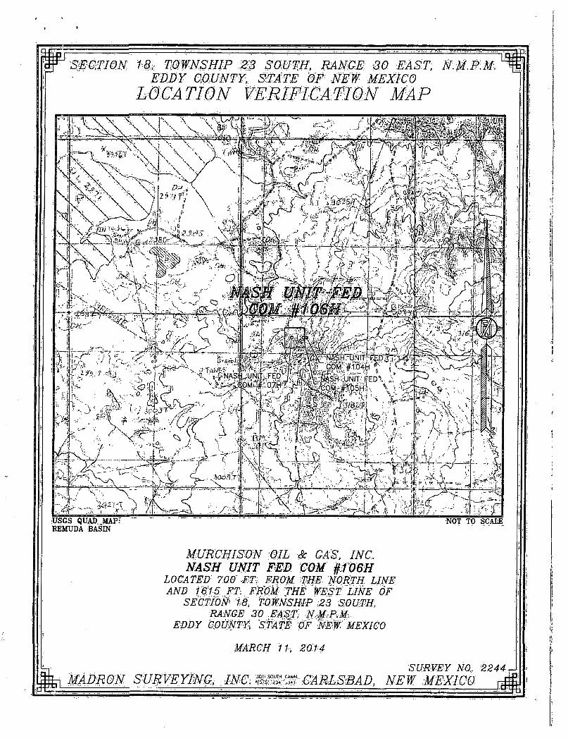
MURCHISON OIL Sc GAS, INC. NASH UNIT FED COM 0O6H
LOCATED 70.0 FT: FROM; 'THE NORTH. LINE AND 1615 FT, FROM THE WEST LINE OF
SECTION 18, TOWNSHIP 23 SOUTH, RANGE 30 EAST, N.M.P.M.
EDDY COUNTY, STATE OF NEW MEXICO
MARCH 11, 2014
MADRON SURVEYING, . INC. SURVEY NO. 2244 J
CARLSBAD, NEW MEXICO

I
SECTION 18, TOWNSHIP 23 SOUTH, RANGE 30 EAST, N.M.P.M. EDDY COUNTY, STATE OF NEW MEXICO
VICINITY MAP
DISTANCES IN MILES
DIRECTIONS' TO LOCATION FROM STATE HIGHWAY, ,128 AND PAVED CR 793 (RAWHIDE) GO SOUTH dN:CR>793V2:6 'MIL^S/TORN;.l iP\0Nf CAJJCHE ROAD. AND GO EAST 0125 MILES TO. A PROPOSED * ROAD SURVEY AND1: FOLLOW' FLAGS EAST 1G0' TO THE. SOUTHWEST CORNER OF PAD FOR THIS LOCATION.
gfcf. MADRON SURVEYING, INC.
NOT TO SCALE
MURCHISON OIL Sc GAS, INC. NASH UNIT FED COM #106H
LOCATED 700 FT FROM THE NORTH LINE AND 1615 FT. FROM THE WEST .LINE OF
SECTION 18, TOWNSHIP 23 SOUTH, RANGE 30 EAST, N.M.P.M
EDDY COUNTY, STATE -OF NEW MEXICO
MARCH 11, 2014
SURVEY NO: 2244
^ f ^ f f CARLSBAD, NEW MEXICO

SECTION 18, TOWNSHIP 23 SOUTH, RANGE 30 EAST, N.M.P.M. EDDY COUNTY, STATE OF NEW MEXICO
AERIAL PHOTO
<, St :fn&f?(
"111111
"* , v * f ^ - ? r ^ "I . ' V - V - ^ O r X , " NASH UNIT FED, \'.-t , . ' ' »,
^ • • ^ 1 ' X w i ^ - v . ' - - .fl'. ' NASH UMT 'FED •// - J A . I. ,.• . .*_-.* ' • & i £ . ' V ' . , V C O M , V-,07H,Jt '\_NASH^UN.r .FED• x H .f , - • ; , " -
••mmmm/Smmmn NOT TO SCALE AERIAL PHOTO: GOOGLE EARTH, MARCH 2012
MURCHISON OIL & GAS, INC NASH UNIT FED COM #106H
LOCATED 700 FT FROM THE NORTH LINE AND 1615 FT FROM THE WEST LINE OF
SECTION 18, TOWNSHIP 23 SOUTH, RANGE 30 EAST, N.M.P.M.
EDDY COUNTY, .STATE OF NEW MEXICO
SURVEY NO. 2244 MARCH 11, 2014
gfej MADRQN SURVEYING, INC. t ^ : . ^ CARLSBAD, NEW MEXICO ^

SECTION 18, TOWNSHIP 23 SOUTH, RANGE 30 EAST, N.M.P.M. EDDY COUNTY, STATE OF NEW MEXICO
ACCESS AERIAL ROUTE MAP
l i lS l i l l I I I
i mww \ NOT TO SCALE AERIAL PHOTO: GOOGLE EARTH MARCH 2012
MURCHISON OIL Sc GAS, INC NASH UNIT FED COM #106H
LOCATED 700 FT FROM THE NORTH LINE AND 1615 FT FROM THE WEST LINE OF
SECTION 18, TOWNSHIP 23 SOUTH, RANGE 30 EAST, NMPM
EDDY COUNTY, STATE OF NEW MEXICO
MARCH 11, 2014 SURVEY NO. 2244
MADRON SURVEYING, INC. CARLSBAD, NEW MEXICO

New Mexico Office of the State Engineer
(with Ownership Information)
WR File Nbr -
C 03720
(acre ft per annum)
Sub
basin Use' Diversion Owner
CUB MON
.,- , County POD Number
0 MOSAIC POTASH CARLSBAD INC ED C 03720 POD1
(R=POD has been replaced and no longer serves this file, (quarters are 1=NW 2=NE 3=SW 4=SE)
C=the file is closed) (quarters are smallest to largest) (NAD83 UTM in meters)
. £ o d e ^ r a n " t _ ^ ^ Source, 6416 4 Sec J lws_R*ng__ , Z _ _ _ X _ _ — ~ . _ Y _
1 1 1 07 23S 30E 600886 3577029 f
Record Coun t : 1
PLSS Search :
Sect ion(s) : 6, 7, 18
Sor ted by: File Number
T o w n s h i p : 23S Range : 30E
The data is furnished by the NMOSE/ISC and is accepted by the recipient with the expressed understanding that the OSE/ISC make no warranties, expressed or implied, concerning the accuracy, completeness, reliability, usability, or suitability for any particular purpose of the data.
5 /9 /14 1:21 P M Page 1 of 1 ACTIVE & INACTIVE POINTS OF DIVERSION

New Mexico Office of the State Engineer
Water Right Summary
get image list
WR File Number: C 03720
Primary Purpose: MON MONITORING WELL
Primary Status:
Total Acres:
Total Diversion:
PMT PERMIT
0
Agent: MOSAIC POTASH CARLSBAD INC
Contact: SARAH GONZALES
Documents on File
Trn # Doc File/Act
§et 5 3 9 4 5 1 E X p L 2014-01-18 \ y images
Status From/
1 2 Transaction Desc. To
PMT APR C-3720 T
Acres Diversion Consumptive
0 0
Current Points of Diversion
POD Number C 03720 POD1
Q Q Q Source 6416 4 SecTwsRng
1 1 1 07 23S 30E
(NAD83 UTM in meters)
X Y 600886 35770291
Other Location Desc MOS-23
The data is furnished by the NMOSE/ISC and is accepted by the recipient with the expressed understanding that the OSE/ISC make no warranties, expressed or implied, concerning the accuracy, completeness, reliability, usability, or suitability for any particular purpose of the data.
Page 1 of 1 WR SUMMARY - C 03720 5/9/14 1:23 PM
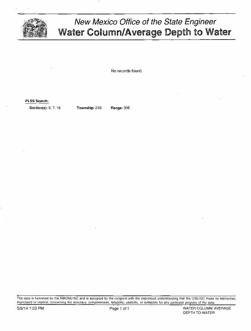
New Mexico Office of the State Engineer ater Column/Average Depth to Water V
t >H^~ --4
No records found.
P L S S Search:
Section(s): 6, 7, 18 Township: 23S Range: 30E
The data is furnished by the NMOSE/ISC and is accepted by the recipient with the expressed understanding that the OSE/ISC make no warranties, expressed or implied, concerning the accuracy, completeness, reliability, usability, or suitability for any particular purpose of the data.
5/9/14 1:23 PM WATER COLUMN/ AVERAGE DEPTH TO WATER
Page 1 of 1
narv Road Access
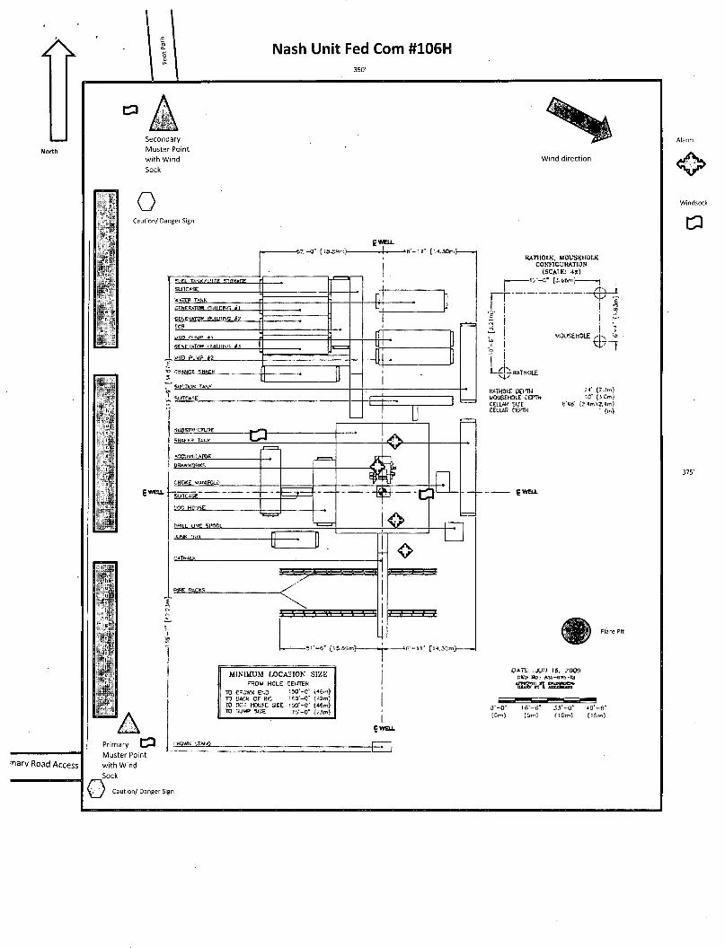
Nash Unit Fed Com #106H
11 I I I
mm
11 .ft
Wind direction
o Caution/ Danger Sign
win Tawi-mr rnntrr
gWEU-
-6? . ' -0 " [ iS .SSr rJ— — J - » 8 ' - t l " Cl4.JK3ln>
wteww.tMwu.rfi screws** spurns
4, win mi» i->
9QC HWSE
Om.i. UNC SPCCi
RATKOU;. MOUSBHOLK CONFIGURATION
(SCAIK: IX) — 1 2 ' - « " [2.66m] -<
WOUSEHOLE
t r t r - f
L. 0»THOLE
HATKOUE DOTH MOUSEHStE BEFTH CELL* M E CELLSR renw
24* (7.3m) !«• (3,0m)
«"M' ft.4mX2,<m) dr.)
a o
sv~a' [is.!i»l- 46 ' - 11" [ U . » m >
9 WELL
MJNIMUM l-OCA'JION SIZK FSOU HOLE CEI/TEK
TO CSCWM E S IJO'-C i « o n )
TO SACK OF DC 160 - 0 ' TO HQS HOUSE SICE 1 W - 0 ' (-Mm) TO SUMP SEE l g - B - (JJp,)
DATE: 16, MOS Hu„- ftsi-ma-tt
l i m n inr i
I £WELL
0 - - O ' IS'-«»" (Cm) (5m)
M ' - 0 " 4 3 ' - 8 *
Primary CP Muster Point with Wind
_Sock
Caution/ Danger Sign

Nash Pad (Weils 104 - 107) - 3000' ROE

35
NASH_UNIT_112H MA<;H II<JIT H - ; H MA<;H U M I T - i n m Ui SB.
NASH_UNIT_104H U M I T 1tV7U N A g U I I M I T i n g U
32
NASH
23 T23S-R29E
28398 19 28902
Murchison Oil and Gas
NASH UNIT
Eddy County NM
2.TO0
~FEET
POSTED WELL DATA API Sarins

Attachment to Form 3160-3
Murchison Oil and Gas Drilling Prognosis
Nash Unit Fed Com #106H
Revision date: July 23, 2014
Surface Location:
Bottom Hole:
476896.049usft N, 667664.578usft E 700' FNL, 1615' FWL
Section 18, T-23-S, R-30-E Eddy County, New Mexico
476896.05usft N, 667664.58usft E 330' FNL, 2260' FWL
Section 6, T-23-S, R-30-E Eddy County, New Mexico
Planned Total Depth: 9206' TVD /20.228' MD
RKB: 3038' GL: 3016'
Preparer: Steve Morris
Murchison Oil and Gas 1 Nash Unit Fed Com#106H

Attachment to Form 3160-3
Contents Article I. Well Overview: 3
Article II. Estimated Formation Tops (geoprognosis with TVD's adjusted to actual KB): 3
Article III. Pressure Control: 3
Article IV. Casing Program (minimum): 7
Article V. Cement Program: 7
Section 5.01 13.375" Surface Casing 7
Section 5.02 9.625" Intermediate Casing 8
Section 5.03 5.5" Production Casing 8
Article VI. Product Descriptions: 9
Article VII. Mud Program: 10
Article VIII. Mud Monitoring System: 10
Article IX. Logging, Drill stem testing and Coring:.:. 10
Article X. Bottom Hole: 11
Article XI. Abnormal Conditions: 11
Article XII. H2S: 11
Article XIII. Directional: 11
Article XIV. Drilling Recorder: 11
Murchison Oil and Gas 2 Nash Unit Fed Com#106H

Attachment to Form 3160-3
Article I. Well Overview:
The Nash Unit Fed Com #106H will be a horizontal well in the Second Bone Spring Sand.
Article II. Estimated Formation Tops (pec-prognosis with TVD's adjusted to actual KB):
Formation , Subsea .Thickness 1 J |H Salado 176' -2861' Salt Base 3038' r Delaware 3246' 209' 3755' Hydrocarbon Bone Spring 7001' 3964' I s t Bone Spring 8027' 4990' 875' Hydrocarbon 2 n d Bone Spring 8902' 5865' 640' Hydrocarbon
No shallow water zones as per the attached POD and water column report.
Article III. Pressure Control: A 13-5/8" 5M BOP and 5M choke manifold will be used. See schematics below. BOP test shall be conducted:
A. when initially installed . B. whenever any seal subject to test pressure is broken J~)tf£s C. following related repairs O / c ^ D. at 30 day intervals
BOP, choke, kill lines, Kelly cock, inside BOP, etc. will be hydro tested to 250psi(low) and 5,000psi(high). The annular will be tested to 250psi (low) and 2500psi (high).
BOP will be function tested on each trip.
All blowout preventer (BOP) and related equipment (BOPE) shall comply with well control requirements as described in Onshore Oil and Gas Order No. 2 and API RP 59 Sec. 17
Minimum Working pressure ofthe blowout preventer (BOP) and related equipment (BOPE) required for drilling below the 9-5/8 inch intermediate casing show shall be 5000 (5M) psi. 5M system requires an HCR valve, remote kill line ad annular to match. The remote kill line is to be installed prior to testing the system and tested to stack pressure.
The appropriate BLM office shall be notified a minimum of 4 hours in advance for a representative to witness the tests.
In a water basin, for all casing strings utilizing slips, these are to be set as soon as the crew and rig are ready and any fallback cement remediation has been done. The casing cut-off and BOP installation can be initiated four hours after installing the slips, which will be approximately six hours after bumping the plug. For those casing strings not using slips the minimum wait time before cut-off is eight hours after bumping the pug. BOP/BOPE testing can begin after cut-off or once cement reaches 500PSI compressive strength (including lead when specified), whichever is greater. However, if the float does not hold, cut-off cannot be initiated until cement reaches 500 psi compressive strength (including lead when specified).
The tests shall be done by an independent service company utilizing a test plug not a cup or J-packer. The operator also has the option of utilizing an independent tester to test without a plug (i.e. against the casing) pursuant to Onshore Order 2 with the pressure not to exceed 70% of the burst rating for the
Murchison Oil and Gas 3 Nash Unit Fed Com#106H

Attachment to Form 3160-3
casing. Any test against the casing must meet the WOC time for water basin (18 hours) or potash (24 hours) or 500 pounds compressive strength, whichever is greater prior to initiating the test (see casing segment as lead cement may be critical item).
a. The results of the test shall be reported to the appropriate BLM office.
b. All Tests are required to be recorded on a calibrated test chart. A copy of the BOP/BOPE test chart and a copy of independent service company test will be submitted to the appropriate BLM office.
c. The BOP/BOPE test shall include a low pressure test from 250 to 300 psi. The test will be held for a minimum of 10 minutes if test is done with a test plug and 30 minutes without a test plug.
A Co-Flex hose may be used from the BOP to the Choke Manifold. If this is used the manufacture specifications and certifications will be furnished prior to use as well will be on location. A variance is requested for the use of the coflex hose. Below is an example of the documentation.
Murchison Oil and Gas 4 Nash Unit Fed Com #106H

Attachment to Form 3160-3
|lfIltlffi^ilMt fm C O M T F T E C H Quality Document
QUALITY CONTROL INSPECTION AND TEST CERTIFICATE
PURCHASER: ContlTech Beattie Co.
CERT. W: 205
P.O. N": 004790
COMTTTECH ORDER N°: 493177
HOSE SERIAL N": 60296
W.P. 68 9 MPs 10000
HOSE TYPE: Choke and Kill Hose
NOMINAL / ACTUAL LENGTH: 10,67 m /10 ,67 m
psi T.P. 103,4 MPa 15000 PS* Duration: 60
Pressure test wttti water 81 ambient temperature
See attachment. (1 page)
t 10mm =
-> 10 mm =
10 Min.
20 MPa
COUPLINGS Type
3* coupling with
4 1/16" Swivel Flange end
Hub
Serial w
228 229
Quality
AISI 4130.
AISI 4130
AISI 4130
HeatN"
H0434
31742
G94S8
ASSET NO.: 66-0628
All metal parts are flawless
API Spec 16 C Temperature rate:"B'
WE CERTIFY THAT THE ABOVE HOSE HAS BEEN MANUFACTURED IN ACCORDANCE WITH THE TERMS OF THE ORDER INSPECTED AND PRESSURE TESTED AS ABOVE WITH SATISFACTORY RESULT. "
STATEMENT OF CONFORMITY: Wo hereby certify that the above DemsAqulament supplied by us ere in conformity with the terms, conditions snd specifications of the above Purchaser-Order and that these tema/OQUIprnant were fabricated Impacted and tested In accordance with the referenced standards, codes snd specifications and meet tha relevant acceptance criteria and design requirements.
COUNTRY OF ORION HUNGARY/EU
21. February 2011.
Inspector QuaPty Control
ContiTech Robber Industrial Ki t
Coajiry Control Deal
Comflocft ftjtofcof bTrdte*ia KA Phono: *jati2SQo W Ttio Can ni Csortgiarl Courny as Beflk aaU
Murchison Oil and Gas 5 Nash Unit Fed Com #106H

Attachment to Form 3160-3
/•age: / / ; •
t
I
urchison Oil and Gas 6 Nash Unit Fed Com#106H

Attachment to Form 3160-3
Downstream of the Choke Manifold assembly 1502(15,OOOpsi working pressure) hammer unions may be used to connect the mud/gas separator. See choke manifold diagram for hammer union possible placement. A variance is requested for the use of these hammer unions.
The well head will be a conventional type well head and NOT a multi-bowl well head.
Article IV. Casing Program (minimum): *A I casing is new API casing. See. Coik
Mole Size ,•„ •eas[ng/ : ;^J iWeightlib/ft"! Grade J Conn ,; ^ a i g e " """.'ii 20" Conductor
16" 13.375" J-55 STC Surface 12.25" 9.625" 47 HCL-80(opccMdSfl) LTC Intermediate 8,5" 5.5" 17 P-110 BTC Production
Size . Collapse psi SF ; Burst psi ; ..SF.:;_; Tension Klbs S F ; JMa)cSejHijigl)epM^D i 13.375 1950 1.45 3450 2.3 675 3.25 4431' 9.625 7100 1.37 6870 1.86 1027 2.76 16,100' 5.5 7480 1.25 10640 1.31 568 3.64 17,000' 13.375" casing will be set 10' below the Salt 9.625" casing will be set +FHftB~BcTTe-Sp^^
Article V.
Section 5.01
Cement Program:
Conductor
- A^/7^~ 3/so 5ee CDfr
Conductor will have cement circulated to surface with the use of a cement head. Cement will set a minimum of 24 hours before the rig will be moved on to location.
Section 5.02
Lead: 0-2548'
13.375" Surface Casing
Gallons/ Sack iBx&iss^.;i^^ii 3£dSititfe§' , /r '";".| 13.5ppg 1.93cuft/sk 1134 9.71 100% ClassC+4%bwoc
Bentonite II+ 2%bwoc Calcium Chloride +0.25lbs/sack Cello
' Flake +. 0.005%bwoc Static Free +0.005gps FP-6L
Tail: 2548 - 3048' sx ; ';.: \- .;' Gallons/ Sack- Excess
14.8ppg 1.34cuft/sk 187 6.35 100% Class C + 1.5% bwoc Calcium Chloride + 0.005 lbs/sack Static Free + 0.005 gps FP-6L
Circulate cement to surface. If cement does not circulate a 1" grout string will be used to
Murchison Oil and Gas Nash Unit Fed Com #106H

Attachment to Form 3160-3
perform a top job.
Cement volumes will be adjusted proportionately once actual casing depth is determined and washout from a fluid caliper.
Section 5.03 9.625" Intermediate Casing
Lead:0 - 7400' Slurry WT Yield Sx .Gallons/ Sack Excess Additives 12.6ppg 2.13cuft/sk 1472 8.81 50% Class C (35:65) +
Poz (Fly Ash) + 4% bwoc Bentonite II + 5% bwoc MPA-5 + 0.25% bwoc FL-52 + 5 lbs/sack LCM-1 + 0.125 lbs/sack Cello Flake + 0.005 lbs/sack Static Free + 0.005 gps FP-6L + 1.2% bwoc Sodium Metasilicate + 5% bwow Sodium Chloride
Tail: 7400 - 7900' Slurry WT Yield Sx i Gallons/ Sack Excess Additives 14.8ppg 1.35cuft/sk 187 6.35 50% Class C
Circulate cement to surface. If cement does not circulate to surface a top squeeze job or casing perforation will be used. As well, a temperature survey or CBL will be performed.
Cement volumes will be adjusted accordingly once actual casing depth is determined and washout from a fluid caliper.
Section 5.04 5.5" Production Casing
Lead: 0-10900' Slurry WT Yield Sx Gallons/ Sack Excess Additives 11-9ppg 2.38cuft/sk 2200 13.22 75% Class H (50:50) +
Poz (Fly Ash) + 10% bwoc Bentonite II + 5% bwow Sodium Chloride + 5 lbs/sack LCM-1 + 0.005 lbs/sack Static Free + 0.005 gps FP-6L
Tail: 10900'-TD HI&yWT Yield Sx Gallons/ Sack Excess Additives
13.2ppg 1.62cuft/sk 2200 9.45 20% Class H (15:61:11) Poz (Fly Ash).CIass H Cement:CSE-2 + 4% bwow Sodium Chloride + 3 lbs/sack LCM-1 + 0.6% bwoc FL-25 + 0.005 gps FP-6L + 0.005% bwoc Static Free
Murchison Oil and Gas 8 Nash Unit Fed Com #106H

Attachment to Form 3160-3
/ Circulate cement to surface. If cement does not circulate to surface a top squeeze job or casing perforation will be used. As well, a temperature survey or CBL will be performed.
Cement volumes will be adjusted accordingly once actual casing depth is determined and washout from a fluid caliper. •
Article VI. Product Descriptions:
Bentonite II P105
CSE-2 An additive which contributes to low density, high compressive strength development of cement slurries at all temperature ranges. This material also controls free water without the need for standard extenders.
Calcium Chloride A powdered, flaked or pelletized material used to decrease thickening time and increase the rate of strength development.
Cello Flake
Graded (3/8 to 3/4 inch) cellophane flakes used as a lost circulation material.
Class C Cement
Intended for use from surface to 6000 ft., and for conditions requiring high early strength and/or sulfate resistance.
Class H Cement Class H cement is an API type, all purpose oil well cement which is used without modification in wells up to 8,000 ft. It possesses a moderate sulfate resistance. With the use of accelerators or retarders, it can be used in a wide range of well depths and temperatures. FL-25 An all purpose salt-tolerant fluid loss additive that provides exceptional fluid loss control across a wide range of temperatures and salinity conditions and remedial cementing applications. FL-52 A water soluble, high molecular weight fluid loss additive used in medium to low density slurries. It is functional from low to high temperature ranges.
FP-6L
A clear liquid that decreases foaming in slurries during mixing.
LCM-1 A graded (8 to 60 mesh) naturally occurring hydrocarbon, asphaltite. It is used as a lost circulation material at low to moderate temperatures and will act as a slurry extender/ Cement compressive strength is reduced.
MPA-5
Used to enhanced compressive, tensile, fleural strength development and reduced permeability
Poz (Fly Ash) A synthetic pozzolan, (primarily Silicon Dioxide). When blended with cement, Pozzolan can be used to create lightweight cement slurries used as either a filler slurry or a sulfate resistant completion cement.
Murchison Oil and Gas 9 Nash Unit Fed Com #106H

Attachment to Form 3160-3
Sodium Chloride At low concentrations, it is used to protect against clay swelling.
Sodium Metasilicate An extender used to produce economical, low density cement slurry.
Static Free An anti-static additive used to prevent air entrainment due to agglomerated particles. Can be used in Cementing and Fracturing operations to aid in the flow of dry materials.
Article VII. Mud Program: Depth Hole Type MW PV YP WL pH Sol % 0-3048 16" Brine 9.8-10 2-4 2-4 NC 9.5-9.7. <3.0 3048-7900 12.25" Cut Brine 8.6-8.9 1-2 1-2 NC 9.5-9.7 <1.0 7900-KOP 8.5" • Cut Brine 8.4-8.6 1-2 1-2 NC 9.5-9.7 <1.0 -KOP-TD 8.5" Cut Brine 8.9-9.1 4-6 4-6 18-20 9.5-9.7 <3.0
Sufficient mud will be on location to control any abnormal conditions encountered. Such as but not limited to a kick, lost circulation and hole sloughing.
Article VIII. Mud Monitoring System: A Pason PVT system will be rigged up prior to spudding the well. A volume monitoring system that measures, calculates, and displays readings from the mud system on the rig to alert the rig crew of impending gas kicks and lost circulation issues.
Components
a) PVT Pit Bull monitor: Acts as the heart of the system, containing all the controls, switches, and alarms. Typically, it is mounted near the driller's console.
b) Junction box: Provides a safe, convenient place for making the wiring connections.
c) Mud probes: Measure the volume of drilling fluid in each individual tank.
d) Flow sensor: Measures the relative amount of mud flowing in the return line.
Article IX. Logging, Drill stem testing and Coring 2 man mud logging will start after surface casing has been set.
8.5" hole will have LWD (Gamma Ray) to section TD.
Murchison Oil and Gas 10 Nash Unit Fed Com #106H

Attachment to Form 3160-3
Article X. Bottom Hole: Temperature is expected to be 149°F, using a 0.767100' gradient. The bottom hole pressure is expected to be 4048psi maximum using a pressure gradient of 0.44psi/ft. With a partially evacuated hole and a gradient of 0.22psi the maximum surface pressure would be 2024psi.
Article XI. Abnormal Conditions: No abnormal conditions are expected. Temperature is expected to be normal. All zones are expected to be normal pressure.
Lost circulation is possible in both the 16" and 12.25" hole sections. 20ppb of LCM will be maintained in the active system at all times while drilling these sections. As well, a 50bbl pill of 50ppb LCM will be premixed in the slug pit in case lost circulation is encountered.
Article XII. H2S: No H2S is expected. But there is the possibility of the presence of H2S. Attached is the H2S response plan.
Article XIII. Directional: Directional survey plan and plot attached.
Article XIV. Drilling Recorder: Rig up EDR & PVT prior to spud to record drilling times and other drilling parameters from surface to TD.
Murchison Oil and Gas 11 Nash Unit Fed Com #106H

Project: Nash Unit Site: Nash Unit Fed Com 106H
Well: Nash Unit Fed Com #1061-1 Wellbore: Nash Unit Fed Com #106H Design: Nash Fed Com 106H
^ MU1CHISON OIL & GAS, INC.
Azimuths to Grid North True North: 4.22°
Magnetic North: 7.18"
Magnetic Field Strength: 48343.4snT
Dip Angle: 60.14° Date: OB/05/2014 Model: IGRF2010
CASING DETAILS FORMATION TOP DETAILS
TVD 200.0 3050.0 7900.0 9086.0
MD 200.0
3050.0 7900.0
20246.0
Name 20"
13 3/8" 9 5/8" 5 1/2"
Size 20 13-3/8 9-5/8 5-1/2
TVDPath MDPath Formation 357.5 357.5 Salado
3039.5 3039.5 Base Salt 3247.5 3247.5 Delaware 3253.5 3253.5 Base Anhydrite 7002.5 7002.5 Bone Spring 8028.5 8028.5 1st Bone Spring 8903.5 8919.5 2nd Bone Spring 9093.5 9241.5 Top Target Sand
1000—-4
2000-
20"
3000 —
I I i 13 3/8" JL-
4000-
5000-
6000-
£ 00
o o o
0J Q
f j 7000-
'•E > E 8000-
9 5/8"
9000—1-
12000-
10000 1-4-4-J-F-r
11000-
Salado
J Base Saft L L
Delaware ""i j - I l : i : :
Base Anhydrite l l M l l i
i x i j : :t:f:d:
t r
J 1 4-TTTT" i ! I
I i
Bone Spring
1 1 1st Bone Spring •
2nd Bone Spring
lop Target Sand
i l I !
i i
I I I !
:l± ..144
+-
I I
4 f+f _l_l
i ! r
i i
T r i ! : l i
! i LJ...
-N
5 1/2"
. Nash Unit Fed Com 106H BHL
_|_4_ I i _t_L
1000 2000 3000 4000 5000 6000 7000 8000
Vertical Section at 3.09° (2000 usft/in) 9000
I I I I I I
10000. 11000 12000 H i r
-1000

Project: Nash Unit Site: Nash Unit Fed'Com 106H Well: Nash Unit Fed Com #106H
Wellbore: Nash Unit Fed Com #106H Design: Nash Fed Com 106H
^ MLKCHISON OIL & GAS, INC. A
Azimuths to Grid North True North: -0.22°
Magnetic North: 7.18°
Magnetic Field Strength: 48343.4snT
Dip'Angle: 60.14° Date: 08/05/2014 Model: IGRF2010
11250-
10625—
10000—
9375-
8750-
8125— - f
7500
6875—
01
o LO CN
6250—
+, 5625-.c •c o
o
5000—
4375—
3750—
3125—
2500—
1875-
1250—
625-
I I I I- | I I I I | I
-3750 -3125 -2500
| I I I I | I I I I | I I I
-1875 -1250 -625 M I | I I I I | I I I I | I I i I | i I I 1 | M I I | I I I I
0 625 1250 1875 2500 3125 3750 4375
West(-)/East(+) (1250 usft/in)
MmCHiSON- OIL& GAS;, .INC.
Murchison Oil and Ga Nash Unit Nash Unit Fed Com 106H
Plan: Nash Fed Com 106H
MOJO Standard Plan 26 June,2014

© MLRCHISON OIL & GAS, INC. MOJO Standard Plan
Company;
Project: ,
Site:
Well:
Wellbore: .
Design:
Planned Survey
Murchison Oil and Gas <
Nash Unit
Nash Unit Fed Com 106H- .
Nash Unit Fed Com #106H
Nash,Unit Fed Com #1061!
140508 Nash Fed Com 106H.
Local Co-ordinate Reference:
TVD Reference: .
MD Reference:
North Reference:
Survey Calculation Method:
Database: '
Site Nash Unit Fed Com 106H
WELL@!3038.5usft(Original,Wel4Elev).'
WELL @ 3038.5usft (Original Well Elev)
Grid
Minimum Curvature
EDM 5000.1 Single User.Db :
MD (usft)
line
> n
' * f
Azu(azimuth)
'Cl TVD (usft) "
TVDSS (usft)" ' •• ' V ,
N/S (usft) '
" :.: 4
t E/W - ' • (us f t ) "
V. Sec (usft) *• '
DLeg;
(-71 OOusft) , l •* Northing* '(usft)
Easting
(usftf 0.0 0.00 0.00 0.0 -3,038.5 0.0 0.0 0.0 0.00 476,896.05 667,664.58
100.0 0.00 0.00 100.0 -2,938.5 0.0 0.0 0.0 0.00 476,896.05 667,664.58
200.0 0.00 0.00 200.0 -2,838.5 0.0 0.0 0.0 0.00 476,896.05 667,664.58
20" • '" •• -\•• . •• • • • • » : . ' A > A ' - ". ,•>;; t.v".' . v-^'v•• •• .• • . ••' »•;>•..'. v: r • ^. : -t!„»~v;:. . •>•: }.\ 300.0 0.00 0.00 300.0 -2,738.5 0.0 0.0 0.0 0.00 476,896.05 667,664.58
357.5 0.00 0.00 357.5 -2,681.0 0.0 0.0 0.0 0.00 476,896.05 667,664.58
Salado '- ' .
:'••' ''": :':v'':>''
400.0 0.00 0.00 400.0 -2,638.5 0.0 0.0 0.0 0.00 476,896.05 667,664.58
500.0 0.00 0.00 500.0 -2,538.5 0.0 0.0 0.0 0.00 476,896.05 667,664.58
600.0 0.00 0.00 600.0 -2,438.5 0.0 0.0 0.0 0.00 476,896.05 667,664.58
700.0 0.00 0.00 700.0 -2,338.5 0.0 0.0 0.0 0.00 476,896.05 667,664.58
800.0 0.00 0.00 800.0 -2,238.5 0.0 0.0 0.0 0.00 476,896.05 667,664.58
900.0 0.00 0.00 900.0 -2,138.5 0.0 0.0 0.0 0.00 476,896.05 667,664.58
1,000.0 0.00 0.00 1,000.0 -2,038.5 0.0 0.0 0.0 0.00 476,896.05 667,664.58
1,100.0 0.00 0.00 1,100.0 -1,938.5 0.0 0.0 0.0 0.00 476,896.05 667,664.58
1,200.0 0.00 0.00 1,200.0 -1,838.5 0.0 0.0 0.0 0.00 476,896.05 667,664.58
1,300.0 0.00 0.00 1,300.0 -1,738.5 0.0 0.0 0.0 0.00 476,896.05 667,664.58
1,400.0 0.00 0.00 1,400.0 -1,638.5 0.0 0.0 0.0 0.00 476,896.05 667,664.58
1,500.0 0.00 0.00 1,500.0 -1,538.5 0.0 0.0 0.0 0.00 476,896.05 667,664.58
1,600.0 0.00 0.00 1,600.0 -1,438.5 0.0 0.0 0.0 0.00 476,896.05 667,664.58
1,700.0 0.00 0.00 1,700.0 -1,338.5 0.0 0.0 0.0 0.00 476,896.05 667,664.58
1,800.0 0.00 0.00 1,800.0 -1,238.5 0.0 0.0 0.0 0.00 476,896.05 667,664.58
1,900.0 0.00 0.00 1,900.0 -1,138.5 0.0 0.0 0.0 0.00 476,896.05 667,664.58
2,000.0 0.00 0.00 2,000.0 -1,038.5 0.0 0.0 0.0 0.00 476,896.05 667,664.58
2,100.0 0.00 0.00 2,100.0 -938.5 0.0 0.0 0.0 0.00 476,896.05 667,664.58
2,200.0 0.00 0.00 2,200.0 -838.5 0.0 0.0 0.0 0.00 476,896.05 667,664.58
2,300.0 0.00 0.00 2,300.0 -738.5 0.0 0.0 0.0 0.00 476,896.05 667,664.58
26/06/2014 1:41:14PM Page 3 COMPASS 5000.1 Build 56

® MU1CHISON OIL & GAS, INC. MOJO Standard Plan
, Company ^
Project
Site
Well: ....
Wellbore:
Design::',- ':. .
Murchison Oil and Gas :>% V^^^^K:^ ; -? - - ' : : ^ •'^•*-:.,v;'.•f,^i%^,:.: Nash Unit » ^ Nash Unit Fed Com 106H
Nash Unit Fed Com #106H ,
Nash Unit Fed Com #106H
140508 Nash Fed Com 106H
«()• •* * ,• .> , , ' '
, ' ' ' '» 1
Local Co ordinate Reference ,
I , TVD Reference * * *, ,
MD Reference ,
• North Reference: • ' •
. Survey Calculation, Method:.-
Database
Site Nasti Unit Fed Com 106H < " e *• ' ^ t >
WELL @ 303*8 5usft (Original Well Elev) v * *
WELL @ 3038 5usft (Original Well Elev) " •
Grid
Minimum Curvature
EDM 5000 1 Single User Db •» •
Project *¥* e>M ~~— » -. "
Map System:
Geo Datum:
Map Zone:
US State Plane 1983
North American Datum 1983
New Mexico Eastern Zone
System Datum: Mean Sea Level
fi^teil^®^^ J%Bf}§N'ash1Unit'Fed Com 106H « < n
Site Position:
From:
Position Uncertainty:
Lat/Long
0.0 usft
Northing:
Easting:
Slot Radius:
476,896.05 U sf t
667,664.58 usft
13-3/16 "
Latitude:
Longitude:
Grid Convergence:
32° 18'37.432 N
103° 55' 27.944 W
0.22 0
* *' ;f|'^Nash*Unit:Fed rComV#;i06H — * ° r r r n — , T - ~
Well Position
Position Uncertainty
+N/-S 0.0 usft
+E/-W 0.0 usft
0.0 usft
Northing:
Easting:
Wellhead Elevation:
476,896.05 usft
667,664.58 usft
usfl
Latitude:
Longitude:
Ground Level:
32° 18' 37.432 N
103° 55' 27.944 W
3,016.5 usft
^ W e J l b o r e 1 « ^ ; ^ ; ( : ;'S'v,*^FlNasi':Uhit,Fed?ebm #106H
r . ,
1
Magnetics . jModeliName .\-?.^ J, ''Sample Date v i , ' . Declination DipAngle ' . ' EieldfStrength >; ; .' (nT),; • • -
i 'fM.e- gr'rS.v.-N. V:,. IGRF2010 08/05/2014 7.40 60.14 48,343
• D e s i g n ; . ; ^ " ^ j --140508 Nash 1 oa Com 106H ' '« " Audit Notes:
Version: Phase: PLAN Tie On Depth: 0.0
^VerticaLSection:, * ^ Y , Depth From (TVD)i
' « ( " « ) ' • * : -.. <E;-W. • • (usft)
* .- Direction
o t
... , . . , , 4 [ , „ V ( ? ^ . ^ " ' V , ^ r 1
0.0 0.0 0.0 3.09
Survey-ToofiProgram
* ' • '.From'. ( u s f t ) H
j Date 26/06/2014 - ^' < ' > Survey-ToofiProgram
* ' • '.From'. ( u s f t ) H (usft) Survey (Wellbore) • • * • •
i "r- ..TooLName
Description*:* ^ -*.,
•'• ""-i w ' i ^
0.0 20.246.6 140508 Nash Fed Com 106H (Nash Unit F MWD MWD - Standard
26/06/2014 1:41:14PM Page 2 COMPASS 5000.1 Build 56

MOJO Standard Plan
^Company
p r o j e c t '
^Site
PI i in I Sin i
MU
- J W e l l i ' v * V ' » J N a h Unit Fed Com #106H
Wellbore •>•>} »|Na h Unit Fed Com #106H
iDesign t ~ « f j 140508 Nash Fed Com 106H
Inc
Sill Azt (azimuth) <• TVD«
(us'ftf TVLlSb
' (usf t * r
N'S% (us f t ) , t»
I W "(u f t ) 4
\ ,V„Sec ^ . ^ D L o g , N o r t o n , L , , , ,
(usft)
2.400.0 0.00 0.00 2.400.0 -638.5 0.0 0.0 0.0 0.00 476.896.05 667.664.58
2,500.0 0.00 0.00 2,500.0 -538.5 0.0 0.0 0.0 0.00 476,896.05 667,664.58
• 2,600.0 0.00 0.00 2,600.0 -438.5 0.0 0.0 'o.o 0.00 476,896.05 667,664.58
2,700.0 0.00 • 0.00 2,700.0 -338:5 0.0 0.0 0.0 0.00 476,896.05 667,664.58
2,800.0 o.oo 0.00 2,800.0 -238.5 0.0 0.0 0.0 0.00 476,896.05 667,664.58
2,900.0 0.00 0.00 2,900.0 -138.5 0.0 0.0 0.0 0.00 476,896.05 667,664.58
3,000.0 0.00 0.00 3,000.0 -38.5 0.0 0.0 • 0.0 0.00 476,896.05 667,664.58
3,039.5 0.00 0.00 3,039.5 1.0 0.0 0.0 0.0 0.00 476,896.05 667,664.58
|p!Base s lit .. , v . . . . . . i j ,
• i t , t i . >. „
3.050.0 0.00 0.00 3.050.0 11:5 0.0 0.0 0.0 0.00 476.896.05 667.664.58
•-••t--"-"^ ... 3.100.0 0.00 0.00 3.100.0 61.5 0.0 0.0 0.0 0.00 476.896.05 667.664.58
3,200.0 0.00 0.00 3,200.0 161.5- 0.0 0.0 0.0 0.00 476,896.05 667,664.58
3.247.5 0.00 0.00 3.247.5 209.0 0.0 0.0 0.0 0.00 476.896.05 667.664.58
FJ Delaware _ Ijlplllllpllllll^lll^l 3.253.5 0.00 3,253.5 215 0 0.0 0 0 0.00 476,896.05 4.58
L Base Anhydrite? I j i l l iBl l l l l l I ^^^^^^^^^^^^^^^ 3.300.0 0.00 0.00 3^300^0 261.5 0.0 0.0 0.0 0.00 476.896.05 667.664.58
3,400.0 0.00 0.00 3,400.0 361.5 0.0 0.0 0.0 0.00 476,896.05 667,664.58
3,500.0 0.00 0.00 3,500.0 461.5 0.0 0.0 0.0 0.00 476,896.05 667,664.58
3,600.0 0.00 0.00 3,600.0 561.5 0.0 0.0 0.0 0.00 476,896.05 667,664.58
3,700.0 0.00 0.00 3,700.0 661.5 0.0 0.0 0.0 0.00 476,896.05 667,664.58
3,800.0 0.00 0.00 3,800.0 761.5 0.0 0.0 0.0 0.00 476,896.05 667,664.58
3,900.0 0.00 0.00 3,900.0 861.5 0.0 0.0 0.0 0.00 476,896.05 667,664.58
4,000.0 0.00 0.00 4,000.0 961.5 0.0 0.0 0.0 0.00 476,896.05 667,664.58
4,100.0 0.00 0.00 4,100.0 1,061.5 0.0 0.0 0.0 0.00 476,896.05 667,664.58
4,200.0 0.00 0.00 4,200.0 1,161.5 0.0 0.0 0.0 0.00 476,896.05 '667,664.58
4,300.0 0.00 0.00 4,300.0 1,261.5 0.0 op 0.0 0.00 476,896.05 667,664.58
26/06/2014 1:41:14PM Page 4 COMPASS 5000.1 Build 56

® MURCHISON OIL & GAS, INO MOJO Standard Plan
Company:
Project:
Site
Well '
Wellbore:
.Design:'-
Murchison Oiland Gas .-:",^,;':
Nash Unit
Nash Unit Fed Com 106H
Nash Unit FedjCom #106H-„
NashUnit Fed Com#106H
!-'U)608 Nash Fori Co~i ; ; IB! i
"4?
LocaliCo-ordinate .Reference:
TVDiReference:, •
MDjReference *
North Reference V
-SurveyCalculationjMethod: *
Database:
Site Nash Unit Fed Com 106H
WELL @;3038:5usft (Original- Well:Elev);»
WELL @ 3038 5usft (Original Well Elev)„
Minimum Curvature *
EDM 5000 1 Single User Db
* MD * (usft)
y Inc
n -
Azi (azimuth) -/.H;
' n TVD (usft)
. TVDSS (usft) .
"It ;-W'.-<T
N/S (usft)
""4"f E/W.' (usft)
A' ' * * t ,s c ' jifi 'f. ••'-.'."• v.:*'
V Sec (usft)
—,—TJ—T 7" . DLeg :••':
• (°/100usft)"
<;;»"' -Northing •(usft) •
"T~T*7W"T ' ^
, Eastjng1 v:.;
1 ("sft) 4,400.0 0.00 0.00 4,400.0 1,361.5 0.0 0.0 0.0 0.00 476,896.05 667,664.58
4,500.0 0.00 0.00 4,500.0 1,461.5 0.0 0.0 0.0 ' 0.00 476,896.05 667,664.58
4,600.0 0.00 0.00 4,600.0 1,561.5 0.0 0.0 0.0 0.00 476,896.05 667,664.58
4,700.0 0.00 0.00 4,700.0 1,661.5 0.0 0.0 0.0 0.00 476,896.05 667,664.58
4,800.0 0.00 0.00 4,800.0 1,761.5 0.0 0.0 0.0 0.00 476,896.05 667,664.58
4,900.0 0.00 0.00 4,900.0 1,861.5 0.0 0.0 0.0 0.00 476,896.05 667,664.58
5,000.0 0.00 0.00 5,000.0 1,961.5 0.0 0.0 0.0 0.00 476,896.05 667,664.58
5,100.0 0.00 0.00 5,100.0 2,061.5 0.0 0.0 0.0 0.00 476,896.05 667,664.58
5,200:0 0.00 0.00 5,200.0 2,161.5 0.0 0.0 0.0 0.00 476,896.05 667,664.58
5,300.0 0.00 0.00 5,300.0 2,261.5 0.0 0.0 0.0 0.00. 476,896.05 667,664.58
5,400.0 0.00 0.00 5,400.0 2,361.5 .0.0 0.0 0.0 0.00 476,896.05 667,664.58
5,500.0 0.00 0.00 5,500.0 2,461.5 0.0 0.0 0.0 0.00 476,896.05 667,664.58
5,600.0 0.00 0.00 5,600.0 2,561.5 0.0 0.0 0.0 0.00 476,896.05 667,664.58
5,700.0 0.00 0.00 5,700.0 2,661.5 0.0 0.0 0.0 0.00 476,896.05 667,664.58
5,800.0 0.00 0.00 5,800.0 2,761.5 0.0 0.0 0.0 0.00 476,896.05 667,664.58
5,900.0 0.00 0.00 5,900.0 2,861.5 0.0 0.0 0.0 0.00 476,896.05 667,664.58
6,000.0 0.00 0.00 6,000.0 2,961.5 0.0 0.0 0.0 0.00 476,896.05 667,664.58
6,100.0 0.00 0.00 6,100.0 3,061.5 0.0 0.0 0.0 0.00 476,896.05 667,664.58
6,200.0 0.00 0.00 6,200.0 3,161.5 0.0 0.0 0.0 0.00 476,896.05 667,664.58
6,300.0 0.00 0.00 6,300.0 3,261.5 0.0 0.0 0.0 0.00 476,896.05 667,664.58
6,400.0 0.00 0.00 6,400.0 3,361.5 0.0 0.0 0.0 0.00 476,896.05 667,664.58
6,500.0 0.00 0.00 6,500.0 3,461.5 0.0 0.0 0.0 0.00 476,896.05 667,664.58
6,600.0 0.00 0.00 6,600.0 3,561.5 0.0 0.0 0.0 0.00 476,896.05 667,664.58
6,700.0 0.00 0.00 6,700.0 3,661.5 0.0 0.0 0.0 0.00 476,896.05 667,664.58
6,800.0 o.oo 0.00 6,800.0 3,761.5 0.0 0.0 0.0 0.00 476,896.05 667,664.58
6,900.0 0.00 0.00 6,900.0 3,861.5 0.0 0.0 0.0 0.00 476,896.05 667,664.58
7,000.0 0.00 0.00 7,000.0 3,961.5 0.0 0.0 0.0 0.00 476,896.05 667,664.58
26/06/2014 1:41:14PM Page 5 COMPASS 5000.1 Build 56

V \ ^ _ *. AC MOJO Standard Plan
Company > Murchison Oil ar
Rro /ecU. . ' ^ N a s h U n i t ^
•• Site . 1 1 Nash Unit Fed Con 106H
|we l l ' v 1 Nash Unit Fed Com H 0 6 H
tWellbore M Na h Unit Fed Com #106H
Design L ~, . ! 140505 Nash Fed Com 106H ~~ ~ * ,;.••rnn^~., • . ~£
SB Local Co ordinate Reference 1* I ' ISite Nash Unit Fed Com 106H ,
WD R e f e r e e * ' '
^ R e f e r e n c e - . ' >" ,
North Reference t * , . Grid
Survey Calculation Method" ' iMinimum Curvature^ v * o5 u u i » t j j V n i i . u i o i i v i i j J i i t i i i « « - i t J % *" ^
Databl le „ ' J E D M 5000-1 Single Use :
WELLfg 3038 5u ft (OnginaJ Well Ele-
WELL ,3) 3038 5usft (Orioinal Well Lie'
I Grid?
Planned Survey
7.002.5 0.00 0.00 7.002.5 3.964.0 0.0 0.0 0.0 0.00 476.896.05 667.664.58
j ~ J t o n e Spn ,,„<t —v 'SB&Sitl&SSSBk Slip 7.100.0 0.00 *~ 0.00 7.100.0 4.061.5 0.0 0.0 0.0 0.00 476.896.05 667.664.58
. 7,200.0 0.00 0.00 7,200.0 4,161.5 0.0 0.0 0.0 0.00 476,896.05 667,664.58
7,300.0 0.00 0.00 7,300.0 4,261.5 0.0 0.0 0.0 0.00 476,896.05 667,664.58
7,400.0 0.00 0.00 7,400.0 4,361.5 0.0 0.0 0.0 0.00 476,896.05 667,664.58
7,500.0 0.00 0.00 7,500.0 4,461.5 0.0 0.0 0.0 0.00 476,896.05 667,664.58
7,600.0 0.00 0.00 7,600.0 4,561.5 0.0 0.0 0.0 0.00 476,896.05 667,664.58
7,700.0 0.00 0.00 7,700.0 4,661.5 0.0 0.0 0.0 0.00 476,896.05 667,664.58
7,800.0 0.00 0.00 7,800.0 4,761.5 0.0 0.0 0.0 0.00 476,896.05 667,664.58
7.900.0 0.00 0.00 7.900.0 4.861.5 0.0 0.0 0.0 0.00 476.896.05
"T 667.664.58
i s m s . n 1 - , . . . llilliSlltlilflii "T 8,000.0 0.00 0.00 8.000.0 4.961.5 0.0 0.0 0.0 0.00 476.896.05 667.664.58
8,028.5 0.00 0.00 8.028.5 4.990.0 0.0 0.0 0.0 0.00 476.896.05 667.664.58
( -1st Bone.Spring H I 8,100.0 0.00 0.00 8.100.0 5.061.5 0.0 0.0 0.0 0.00 476.896.05 667.664.58
8,200.0 0.00 0.00 8,200.0 5,161.5 0.0 0.0 0.0 0.00 476,896.05 667,664.58
8,300.0 0.00 0.00 8,300.0 5,261.5 0.0 0.0 0.0 0.00 476,896.05 667,664.58
8,400.0 0.00 0.00 8,400.0 5,361.5 0.0 0.0 0.0 0.00 476,896.05 667,664.58
8,500.0 0.00 0.00 8,500.0 5,461.5 0.0 0.0 0.0 0.00 476,896.05 667,664.58
8,600.0 0.00 0.00 8,600.0 5,561.5 0.0 0.0 0.0 0.00 476.896.05 667,664.58
8,638.0 0.00 0.00 8,638.0 5,599.5 0.0 0.0 0.0 0.00 476,896.05 667,664.58
8,650.0 • 1.44 70.00 8,650.0 5,611.5 0.1 0.1 0.1 12.00 476,896.10 667,664.72
8,675.0 4.44 70.00 8,675.0 5,636.5 0.5 1.3 0.6 . 12.00 476,896.54 667,665.92
-8,700.0 7.44 70.00' 8,699.8 5,661.3 1.4 3.8 1.6 12.00 476,897.42 667,668.36
. 8,725.0 10.44 70.00 8,724.5 5,686.0 2.7 7.4 3.1 12.00 476,898.75 667,672.01
8,750.0 13.44 70.00 8,749.0 5,710.5 4.5 12.3 '5.1 12.00 476,900.52 667,676.87
25/06/2014 1:41:14PM Page 6 COMPASS 5000.1 Build 56
<g> MU1CHISON OIL & GAS, INC. MOJO Standard Plan
Company /
Project
Site ,
Well
Wellbore
Design:-
Mi
Murchison Oil and Gas ^^xs- v-f .*Ti: s: • '.:;c*J-..:>'yi-.<:, <^%|->$:^,';%& Nash Unit , *
Nash Unit:Fed:Com:i06Ha
Nash Unit Fed Com #106H *5 < *<
Nash Unit Fed Com #106H
140508 Nash Fed Com 106HS-iV.;:
, i * i Local Co ordinate Reference '•<:• 'Y. :*s ' t - r - '^yz.^wz^c*: '~~:~~ • ' TVD Reference
> w ^ i ^ j MD Reference •' ?. • . '
" - - North Reference - «
Survey CalculationtMethod
Site Nash Unit Fed Com 106H
WELL @ 3038 5usft (Original Well Elev)
WELL @ 3038 5usft (Original Well Elev) * *
Minimum Curvature /
EDM 5000 1 Single User Db
Planned Survey^
'f~.
MD (usft) " „ _
1 J - > * 1 Planned Survey^
'f~.
MD (usft) " „ _
. Inc -
c>, . Azi (azimuth) - TVD
(usft) 1 * TVDSS ' (usft)
N/S (usft) I " ,
E/W
, <Hsft> •• V. Sec
& i(ujft)
DLeg
C/IOOusft)";
: Northing? " • (usft) :.• .
- Easting -(usft)
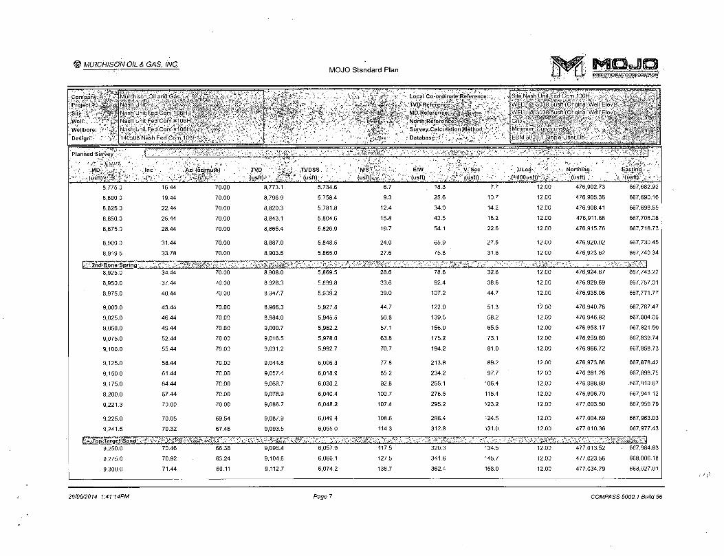
8.775.0 16.44 70.00 8.773.1 5.734.6 6.7 18.3 7.7 12.00 476.902.73 667.682.92
8,800.0 19.44 70.00 8,796.9 5,758.4 9.3 25.6 10.7 12.00 476,905.36 667,690.16
8,825.0 22.44 70.00 8,820.3 5,781.8 12.4 34.0 14.2 12.00 476,908.41 667,698.55
8,850.0 25.44 70.00 8,843.1 5,804.6 15.8 43.5 18.2 12.00 476,911.88 667,708.08
8,875.0 28.44 70.00 8,865.4 5,826.9 19.7 54.1 22.6 12.00 476,915.76 667,718.73
8,900.0 31.44 70.00 8,887.0 5,848.5 24.0 65.9 27.5 12.00 476,920.02 667,730.45
8,919.5 33.78 70.00 8,903.5 5,865.0 27.6 75.8 31.6 12.00 476,923.62 667,740.34
2nd'Bdne':Sprihg v r v + ' . . . .. 8,925.0 34.44 70.00 8,908.0 5,869.5 28.6 78.6 32.8 12.00 476,924.67 667,743.22
8,950.0 37.44 70.00 8,928.3 5,889.8 33.6 92.4 38.6 12.00 476,929.69 667,757.01
8,975.0 40.44 70.00 8,947.7 5,909.2 39.0 107.2 44.7 12.00 476,935.06 667,771.77
9,000.0 43.44 70.00 8,966.3 5,927.8 44.7 122.9 51.3 12.00 476,940.78 667,787.47
9,025.0 46.44 70.00 8,984.0 5,945.5 50.8 139.5 58.2 12.00 476,946.82 667 ;804.06
9,050.0 49.44 70.00 9,000.7 5,962.2 57.1 156.9 65.5 12.00 476,953.17 667,821.50
9,075.0 52.44 70.00 9,016.5 5,978.0 63.8 175.2 73.1 12.00 476,959.80 667,839.74
9,100.0 55.44 70.00 9,031.2 5,992.7 70.7 194.2 81.0 12.00 476,966.72 667,858.73
9,125.0 58.44 70.00 9,044.8 6,006.3 77.8 213.8 89.2 12.00 476,973.88 667,878.42
9,150.0 61.44 70.00 9,057.4 6,018.9 85.2 234.2 97.7 12.00 476,981.28 667,898.75
9,175.0 64.44 70:00 9,068.7 6,030.2 92.8 255.1 106.4 12.00 476,988.89 .667,919.67
9,200.0 67.44 70.00 9,078.9 6,040.4 100.7 276.5 115.4 12.00 476,996.70 667,941.12
9,221.3 70.00 70.00 9,086.7 6,048.2 107.4 295.2 123.2 12.00 477,003.50 667,959.79
9,225.0 70.05 69.54 9,087.9 6,049.4 108.6 298.4 124.5 12.00 477,004.69 667,963.03
9,241.5 70.32 67.46 9,093.5 6,055.0 114.3 312.8 131.0 12.00 477,010.36 667,977.43
1. :.TotvTarqet SahdV- - ^ V ^ V'- '^'<,U- ;;:* 1 - : i ' t«Ji\5.W^%%i. 9,250.0 70.46 66.38 9,096.4 6,057.9 117.5 ' 320.3 134.5 12.00 477,013.52 667,984.83
9,275.0 70.92 63.24 9,104.6 6,066.1 127.5 341.6 145.7 12.00 477,023.56 668,006.18
9,300.0 71.44 60.11 9,112.7 6,074.2 138.7 362.4 158.0 12.00 477,034.79 668,027.01
2S/0S/2014 1:41:14PM Page 7 COMPASS 5000.1 Build 56

@IMLRCHISONI PIL & GAS, INC.. MOJO Standard Plan
cmccnoiM, coiwoswinoH'
" " V T i •'" T — Local.Co-ordinate-;Reference:,:
TVD Reference " v» * v
" MO Reference: . .: < r: ' ••-.>
. North Reference: • J :
•Survey Calculation Method:
: (Database: * : v
Company:
Project:
Site:
Well:
Wellbore: *
Design:
Murchison Oil and Gas s
Nash Unit
Nash Unit Fed Com 106H
Nash Unit Fed Com #106H
NashiUriif Fed .Com-#.106H«>
140508 Nash Fed=Com>106H:S
Site Nash Unit Fed Com 106H * ,
WEL#@!3038.5usft;(Originai:Well Elev) *
WEl!L:@:3038;5usft (Original!Well Elev)
Grid %
Minimum.Curvature ••- v-\ •>/.
EDM 5000:1 Single User.Db-V
* MD* ^ j i ,
(usft) * \ * Inc
C)
j-Azi (azimuth)%
(V"' *
r "•»—7 ,'"s' *iTVD V 1% >"
. v (us f t ) -
"V fm TVDSS
* (usft) * (usft)* tt t »
E/W (usft)
V Sec ' (usft)
DLeg ' 4- < (°/1 OOusft)/ * ' 1
K—r-?
Northing. » »Y ^ (usft)
Ea tinq
( u s f t ) ; / * _ I
9,325.0 72.00 57.01 9,120.5 . 6,082.0 151.1 382.7 171.5 12.00 . 477,047.17 668,047.26
9,350.0 72.62 53.93 9,128.1 6,089.6 164.6 402.3 186.0 12.00 477,060.67 668,066.87
9,375.0 73.28 50.87 9,135.5 6,097.0 179.2 421.2 201.6 12.00 477,075.25 668,085.81
9,400.0 73.98 47.83 9,142.5 6,104.0 194.8 439.4 218.2 12.00 477,090.88 668,104.00
9,425.0 74.73 44.81 9,149.3 6,110.8 211.5 456.8 235.7 12.00 477,107.50 668,121.41
9,450.0 75.52 41.82 9,155.7 6,117.2 229.0 473.4 254.2 12.00 477,125.08 668,137.98
9,475.0 76.35 38.84 9,161.8 6,123.3 247.5 489.1 273.5 12.00 477,143.57 668,153.67
9,500.0 77.21 35.89 9,167.5 6,129.0 266.9 503.9 293.6 12.00 477,162.91 668,168.44
9,525.0 78.10 32.96 9,172.8 6,134.3 287.0 517.7 314.4 12.00 477,183.05 668,182.25
9,550.0 79.02 30.05 9,177.8 6,139.3 307.9 530.5 336.0 12.00 477,203.94 668,195.05
9,575.0 79.98 27.15 9,182.3 6,143.8 329.5 542.2 358.2 12.00 477,225.52 668,206.81
9,600.0 80.95 24.28 9,186.5 6,148.0 351.7 552.9 380.9 12.00 477,247.73 668,217.51
9,625.0 81.95 21.42 9,190.2 6,151.7 374.5 562.5 404.2 12.00 477,270.51 668,227.10
9,650.0 82.97 18.57 9,193.5 6,155.0 397.7 571.0 427.9 12.00 477,293.80 668,235.58
9,675.0 84.00 15.74 9,196.3 6,157.8 421.5 578.3 452.0 12.00 477,317.53 668,242.90
9,700.0 85.05 12.91 9,198.7 6,160.2 445.6 584.5 476.4 12.00 477,341.64 668,249.06
9,725.0 86.11 10.10 9,200.6 6,162.1 470.0 589.4 501.1 12.00 477,366.06 668,254.03
9,750.0 87.19 7.29 9,202.1 6,163.6 494.7 593.2 525.9 12.00 477,390.73 668,257.80
9,775.0 88.26 4.49 9,203.1 6,164.6 519.5 595.8 550.8 12.00 477,415.57 668,260.36
9,800.0 89.35 1.69 9,203.6 6,165.1 544.5 597.1 575.8 12.00 477,440.53 668,261.71
9,815.1 90.00 0.00 9,203.7 6,165.2 559.6 597.4 590.9 12.00 477,455.63 668,261.93
9,900.0 90.09 360.00 9,203.6 6,165.1 644.5 597.4 675.7 0.11 477,540.53 668,261.93
10,000.0 90.21 359.99 9,203.4 6,164.9 744.5 597.3 775.5 0.11 477,640.53 668,261.92
10,100.0 90.32 359.99 9,202.9 6,164.4 844.5 597.3 875.4 0.11 477,740.52 668,261.90
10,200.0 90.43 359.98 9,202.3 6,163.8 944.5 597.3 975.3 0.11 477,840.52 668,261.87
10,300.0 90.54 359.98 9,201.4 6,162.9 1,044.5 597.3 1,075.1 0.11 477,940.52 668,261.84
10,400.0 90.65 359.97 9,200.4 6,161.9 1,144.5 597.2 1,174.9 0.11 478,040.51 668,261.79
26/06/2014 1:41:14PM Page B COMPASS 5000.1 Build 56

^MUICHISON OILA.GASiINC. ;
MOJO Standard Plan MRECTroWSt'COKOStflWCW'
P l a n n e d S u r v e y
* (USft) • ^ n ~' -ii/ . "< Azi (azimuth) TVD ,
(usft) ' TVDSS
- ' (us f t ) i \ ' - N , S i
l < u s f t '> , '
E/W (usft)
4 « ' V Sec
\ *. (»sft), < 1
DLeg ^("/lOOusftj"'
-^Northing*:'', »j, i. Jf (usft)* ^4 i
^ Eastingf
i * J j ( u s f t ) » ' ; s
10,413.7 90.67 359.97 9,200.2 6,161.7 1,158.2 597.2 1,188.7 0.11 478,054.24 668,261.79
10,500.0 90.67 359.97 9,199.2 6,160.7 1,244.5 597.2 1,274.8 0.00 478,140.51 668,261.74
10,600.0 90.67 359.97 9,198.1 6,159.6 1,344.5 597.1 1,374.6 0.00 478,240.50 668,261.69
10,700.0 90.67 359.97 9,196.9 6,158.4 1,444.4 597.1 1,474.5 0.00 478,340.49 668,261.65
10,800.0 90.67 359.97 9,195.7 6,157.2 1,544.4 597.0 1,574.3 0.00 478,440.49 668,261.60
10,900.0 90.67 359.97 9,194.6 6,156.1 1,644.4 597.0 1,674.2 o.oo 478,540.48 668,261.55
11,000.0 90.67 359.97 9,193.4 6,154.9 1,744.4 596.9 1,774.0 0.00 478,640.47 668,261.50
11,100.0 90.67 359.97 9,192.2 6,153.7 1,844.4 596.9 1,873.9 0.00 478,740.47 668,261.45
11,200.0 90.67 359.97 9,191.1 6,152.6 1,944.4 596.8 1,973.7 0.00 478,840.46 668,261.40
11,300.0 90.67 359.97 9,189.9 6,151.4 2,044.4 596.8 2,073.6 0.00 478,940.45 668,261.35
11,400.0 90.67 359.97 9,188.8 6,150.3 2,144.4 596.7 2,173.4 0.00 479,040.45 668,261.30
11,500.0 90.67 359.97 9,187.6 6,149.1 2,244.4 596.7 2,273.3 0.00 479,140.44 668,261.25
11,600.0 90.67 359.97 9,186.4 6,147.9 2,344.4 596.6 2,373.1 0.00 479,240.43 668,261.20
11,700.0 90.67 359.97 9,185.3 6,146.8 2,444.4 596.6 2,472.9 0.00 479,340.43 668,261.16
11,800.0 90.67 359.97 9,184.1 6,145.6 2,544.4 596.5 2,572.8 0.00 479,440.42 668,261.11
11,900.0 90.67 359.97 9,183.0 6,144.5 2,644.4 596.5 2,672.6 0.00 479,540.41 668,261.06
12,000.0 90.67 359.97 9,181.8 6,143.3 2,744.4 596.4 2,772.5 0.00 479,640.41 668,261.01
12,100.0 90.67 359.97 9,180.6 6,142.1 2,844.3 596.4 2,872.3 0.00 479,740.40 668,260.96
12,200.0 90.67 359.97 9,179.5 6,141.0 2,944.3 596.3 2,972.2 0.00 479,840.39 668,260.91
12,300.0 90.67 359.97 9,178.3 6,139.8 3,044.3 596.3 3,072.0 0.00 479,940.39 668,260.86
12,400.0 90.67 359.97 9,177.1 6,138.6 3,144.3 596.2 3,171.9 0.00 480,040.38 668,260.81
12,500.0 90.67 359.97 9,176.0 6,137.5 3,244.3 596.2 3,271.7 0.00 480,140.37 668,260.76
12,600.0 90.67 359.97 9,174.8 6,136.3 3,344.3 596.1 3,371.6 0.00 480,240.36 668,260.71
12,700.0 90.67 359.97 9,173.7 6,135.2 3,444.3 596.1 3,471.4 0.00 480,340.36 668,260.67
12,800.0 90.67 359.97 9,172.5 6,134.0 3,544.3 596.0 3,571.2 0.00 480,440.35 668,260.62
.12,900.0 90.67 359.97 9,171.3 6,132.8 3,644.3 596.0 3,671.1 0.00 480,540.34 668,260.57
13,000.0 90.67 359.97 9,170.2 6,131.7 3,744.3 595.9 3,770.9 0.00 480,640.34 668,260.52
26/06/2014 1:41:14PM Page 9 COMPASS 5000.1 Build 56

© L \ . r .-><.)r\ MOJO Standard Plan
tWCTO! SJ "vWOn.'V.ICr,
I Murchison Oil and Gas
'Nash Ur Project »« *«
Site »,y, H A . jNash Unit F ed Corr 106H
Well - O r well tWellbores - K
De ig 'n"" 1 ** <"J8 140518 Na^h Fed Com 106H
Nash Unit Fed Com #106H
Nash Unit Fed Com #106H
, w LocaJ|Co-ordinate'<Reference K ^
v ^ T V D t t e f e r e n c e V * ^ J W E L L @ 3038 5usft (Original Well Elev) , MD Reference - j ~ . "WFLL @ 3C18 "bu<5ft (O iqinal Well Flev)
• iSurveyiCalculation.Method A *W Minimum Curvature
. * * . » / ' , * Database, ,: - - „ / 4 ^EDMi5000»lSinglc U o-Dh
(Site Na h Unit Fed Com "OBH
_'< v > " I "*V-' Planned Survey^
: M D - J , . H M w /Azi (azimuth) ivn (usft) *
TVDSS' (u f t ) ;
L i tinn - ' (usf t ) -
13.100.0
13,200.0
13,300.0
13,400.0
13,500.0
13,600.0
13,700.0
13,800.0
13,900.0
14,000.0
14,100.0
14,200.0
14,300.0
14,400.0
14,500.0
14,600.0
14,700.0
14,800.0
14,900.0
15,000.0
15,100.0
15,200.0
15,300.0
15,400.0
15,500.0
15,600.0
15,700.0
90.67
90.67
•90.67
90.67 ,
90.67
90.67
90.67
90.67
90.67
90.67
90.67
90.67
90.67
90.67
90.67
90.67
90.67
90.67
90.67
90.67
90.67
90.67
90.67
90.67
90.67
90.67
90.67
359:97
359.97
359.97
359.97
359.97
359.97
359.97
359.97
359.97
359.97
359.97
359.97
359.97
359.97
359.97
359.97
359.97
359.97
359.97
359.97
359.97
359.97
359.97
359.97
359.97
359.97
359.97
167.9
,166.7
165.5
164.4
163.2
162.0
160.9
159.7
158.6
157.4
156.2
155.1
153.9
152.8
151.6
150.4
149.3
148.1
146.9
145.8
144.6
143.5
142.3
141.1
140.0
138.8
6.130.5
6,129.4
6,128.2.
' 6,127.0
6,125.9
6,124.7
6,123.5
6,122.4
6,121.2
6,120.1
6,118.9
6,117.7
6,116.6
6,115.4
6,114.3
6,113.1
6,111.9
6,110.8
6,109.6
6,108.4
6,107.3
6,106.1
.6,105.0
6,103.8
• 6,102.6
6,101.5
6,100.3
3:844.3
3,944.3
4,044.3
4,144.3
4,244.3
4,344.2
4,444.2
4,544.2
4,644.2
4,744.2
4,844.2
4,944.2
5,044.2
5,144.2
5,244.2
5,344.2
5,444.2
5,544.2
5,644.2
5,744.2
5,844.1
5,944.1
6,044.1
6,144.1
6,244.1
6,344.1
6,444.1
595.9
595.8
595.8
595.7
595.7
595.6
595.6
595.5
595.5
595.5
595.4
595.4
595.3
595.3
595.2
595.2
595.1
595.1
595.0
595.0
594.9
594.9
594.8
594.8
594.7
594.7
594.6
3.870.8
3,970.6
4,070.5
4,170.3
4,270.2
4,370.0
4,469.9
4,569.7
4,669.5
4,769.4
4,869.2
4,969.1
5,068.9
5,168.8
5,268.6
5,368.5
5,'468.3
5,568.2
5,668.0
5,767.8
5,867.7
5,967.5
6,067.4
6,167.2
6,267.1
6,366.9
6,466.8
0.00
0.00
0.00
0.00
0.00
0.00
0.00
0.00
0.00
0.00
0.00
0.00
0.00
0.00
0.00
0.00
0.00
0.00
0.00
0.00
0.00
0.00
0.00
0.00
0.00
0.00
0.00
480.740.33
480,840.32
480,940.32
481,040.31
481,140.30
481.240.30
481,340.29
481,440.28
481,540.28
481,640.27
481,740.26
481,840.26
481,940.25
482,040.24
482,140.24
482,240.23
482,340.22
482,440.22
482,540.21
482,640.20
482,740.20
482,840.19
482,940.18
483,040.18
483,140.17
483,240.16
483,340.16
668.260.47
668,260.42
668,260.37
668,260.32
. 668,260.27
668,260.22
668,260.18
668,260.13
668,260.08
668,260.03
668,259.98
668,259.93
668,259.88
668,259.83
668,259.78
668,259.73
668,259.69
668,259.64
668,259.59
668,259.54
668,259.49
668,259.44
668,259.39
668,259.34
668,259.29
668,259.24
668,259.20
26/06/2014 1:41:14PM Page 10 COMPASS 5000:1 Build 56

© v i 'tc \o u ' / f ' \ ' MOJO Standard Plan C m c c — O W i CvHfCHWTICN
I Murchi on Oil and Ga \ <Nash Ui
Company .
iP ro jec t , „ „
*Sito . \ t V* i |Na h Unit Fed Com 106H
W l l " 1 f j t f l N a h Unit Fed Com #106H ,
Wellbore - " ' ]Nash U lit Ted Com fclOGH
^Design ' J140508 Na h Fed Com "0611 :
L L I C j i Ft.If i lief
TVD Reference *
MD Reference - ""^
North Referei
Survey Calculation Method
Database' ^ v
•jSite Nash Unit Fed Com -Of I WELL (? 3038 5usft (Origin
v . *a WELL @ 3038 5usff(Oriqin< ' 4- C \
, #4MinimumiGurva ure *
Planned Survey
sft (u* f t ) ' ^ n ( i isft f f ^ * „ - ' ' ( t , ( us f t ) - , 1 ' ^ ; mslt
15,800.0 90.67 359.97 9,137.7 6,099.2 6,544.1 594.6 6,566.6 0.00 483,440.15 668,259.15
15,900.0 90.67 359.97 9,136.5 '6,098.0 6,644.1 594.5 6,666.5 0.00 483,540.14 668,259.10
16,000.0 90.67 359.97 9,135.3 6,096.8 6,744.1 594.5 6,766.3 0.00 483,640.14 668,259.05
16,100.0 90.67 359.97 9,134.2 6,095.7 6,844.1 594.4 6,866.2 0.00 483,740.13 668,259.00
16,200.0 90.67 359.97 9,133.0 6,094.5 6,944.1 594.4 6,966.0 0.00 483,840.12 668,258.95
16,300.0 90.67 359.97 9,131.8 .6,093.3 7,044.1 . 594.3 7,065.8 0.00 483,940.11 668,258.90
16,400.0 90.67 359.97 9,130.7 6,092.2 7,144.1 594.3 7,165.7 0.00 484,040.11 668,258.85
16,500.0 90.67 359.97 9,129.5 6,091.0 7,244.1 594.2 7,265.5 0.00' 484,140.10 . 668,258.80
16,600.0 90.67 359.97 9,128.4 6,089.9 7,344.0 594.2 7,365.4 0.00 484,240.09 668,258.75
16,700.0 90.67 359.97 9,127.2 . 6,088.7 7,444.0 594.1 7,465.2 0.00 . 484,340.09 668,258.71
16,800.0 90.67 359.97 9,126.0 6,087.5 7,544.0 594.1 7,565.1 0.00 484,440.08 668,258.66
16,900.0 90.67 359.97 9,124.9 6,086.4 7,644.0 594.0 7,664.9 0.00 484,540.07 668,258.61
17,000.0 90.67 359.97-- 9,123.7 6,085.2 7,744.0 594.0 7,764.8 0.00 484,640.07 668,258.56
17,100.0 90.67 359.97 9,122.6 6,084.1 7,844.0 593.9 " 7,864.6 0.00 484,740.06 668,258.51
17,200.0 90.67 359.97 9,121.4 6,082.9 7,944.0 593.9 7,964.5 0.00 484,840.05 ' 668,258.46
17,300.0 90.67 359.97 9,120.2 6,081.7 8,044.0 593.8 8,064.3 0.00 484,940.05 668,258.41
17,400.0 90.67 359.97 9,119.1 6,080.6 8,144.0 . 593.8 8,164.1 0.00 485,040.04 668,258.36
17,500.0 90.67 359.97 9,117.9 6,079.4 8,244.0 593.7 8,264.0 0.00 485,140.03 668,258.31
17,600.0 90.67 359.97 9,116.7 6,078.2 8,344.0 593.7 8,363.8 0.00 485,240.03 668,258.26
17,700.0 90.67 359.97 9,115.6 6,077.1 .8,444.0 593.6 8,463.7 0.00 485,340.02 668,258.22
17,800.0 90.67 359.97 9,114.4 6,075.9 8,544.0 593.6 8,563.5 0.00 485,440.01 668,258.17
17,900.0 90.67 359.97 9,113.3 6,074.8 8,644.0 593.5 8,663.4 0.00 485,540.01 668,258.12
18,000.0 90.67 359.97 9,112.1 ' 6,073.6 8,744.0 593.5 8,763.2 0.00 485,640.00 668,258.07
18,100.0 90.67 359.97 9,110.9 6,072.4 8,843.9 593.4 8,863.1 0.00 485,739.99 668,258.02
18,200.0 90.67 359.97 9,109.8 6,071.3 8,943.9 593.4 8,962.9 0.00 485,839.99 668,257.97
18,300.0 90.67 359.97 9,108.6 6,070.1 9,043.9 593.3 9,062.8 0.00 485,939.98 668,257.92
18,400.0 90.67 359.97 9,107.5 6,069.0 9,143.9 593.3 - 9,162.6 0.00 486,039.97 668,257.87
26/06/2014 1:41:14PM Page 11 COMPASS 5000.1 Build 56

h'S MOJO Standard Plan
Planned Survey
\ . MD ' Inc
n Azi (azimuth)
>-l ) (usft)' " , (u * (us Northing
, (ustt) _ - ; Easting f *
i .
(usfV*' 18.500.0 90.67 359.97 9.106.3 6.067.8 9.243.9 593.2 9.262.4 0.00 486.139.97 668.257:82
18,600.0 90.67 359.97 9,105.1 6,066.6 9,343.9 593.2 9,362.3 0.00 486,239.96 668,257.77
18,700.0 90.67 359.97. 9,104.0 6,065.5 9,443.9 593.1 9,462.1 0.00 486,339.95 668,257.73
18,800.0 90.67 359.97 9,102.8 6,064.3 9,543.9 593.1 9,562.0 0.00 486,439.95 668,257.68
18,900.0 90.67 359.97 9,101.6 6,063.1 9,643.9 593.0 9,661.8 0.00 486,539.94 668,257.63
19,000.0 90.67 359.97 - 9,100.5 6,062.0 9,743.9 593.0 9,761.7 0.00 486,639.93 668,257.58
19,100.0 90.67 359.97 9,099.3 6,060.8 9,843.9 593.0 9,861.5 0.00 486,739.93 668,257.53
19,200.0 90.67 359.97 9,098.2 6,059,7 9,943.9 592.9 9,961.4 0.00 486,839.92 668,257:48
19,300.0 90.67 359.97 9,097.0 6,058.5 10,043.9 592.9 10,061.2 0.00 486,939.91 668,257.43
19,400.0 90.67 . 359.97 9,095.8 6,057.3 10,143.9 592.8 10,161.1 0.00 487,039.91 668,257.38
19,500.0 90.67 359.97 9,094.7 6,056.2 10,243.8 592.8 10,260.9 0.00 487,139.90 668,257.33
19,600.0 90.67 359.97 9,093.5 6,055.0 10,343.8 592.7 10,360.8 0.00 487,239.89 • 668,257.28
19,700.0 90.67 359.97 9,092.3 6,053.8 10,443.8 592.7 10,460.6 0.00 487,339.88 668,257.24
19,800.0 90.67 359.97 9,091,2 6,052.7 10,543.8 592.6 10,560.4 0.00 487,439.88 668,257.19
19,900.0 . 90.67 359.97 9,090.0 6,051.5 10,643.8 592.6 10,660.3 0.00 487,539.87 668,257.14
20,000.0 90.67 359.97 9,088.9 6,050.4 10,743.8 592.5 10,760.1 0.00 487,639.86 668,257.09
20,100.0 90.67 359.97 9,087.7 6,049.2 10,843.8 592.5 10,860.0 0.00 487,739.86 668,257.04
20,200.0 90.67 359.97 9,086.5 6,048.0 10,943.8 592.4 10,959.8 0.00 487,839.85 668,256.99
20,242.3 90.67 359.97 9,086.1 6,047.6 10,986.1 - 592.4 11,002.0 0.00 487,882.13 668,256.97
20,246.0 90.67 359.97 9.086.0 6,047.5 10,989.8 592.4 11,005.8 0.11 487,885.85 668,256.97
20,246.6 668,256.97
26/06/20M 1:41:14PM Page 12 COMPASS 5000.1 Build 56
)

M O J O S t a n d a r d P lan f ^ f f M O J O ~~i m
Local Co ordinate Reference
*TVD Referenc
MD Referenct
NortlvReferei
Survey.'Calculation Method
fttMurchison Oi}|ahdjGas
jNash Unit
Site 1 | Ma h Unit Fed Con 106H
i.Well * » 1 Nash Unit Fed Com #106H
[Na h Unit Fed Com #106H
> Design"**,, * , *A 140508 Na h Fell Com
Compa'ny Project
n'v iWellbore:!
Warn Site Na h Unit Fed Com 1C
WELL (3 3038 5u ft (Original Well Elcyj
iSncM^^^^K^^^^^^^S Mjn i m ti m|Gju rva tuf's^^i^W^M^^if^iMM
EDM 5000 1 Snale L ^ — — • —• „ — = — ~ — —
aCasingiRoints , r „ 1 . Measured ^ Vertical
^ / ' Dep th ' * \ foeVth
N a m e ^ '
200.0 20"
3,050.0 13 3/8"
7,900.0 9 5/8"
9,086.0 5 1/2"
'Cas ing ' Diameter
811111 sfW Diameter A—
"'A (,) mm 200.0
3,050.0
7,900.0
20,246.0
20
13-3/8
9-5/8
5-1/2
20
16
12-1/4
8-1/2
3.253.5
9,241.5
3,039.5
357.5
8,028,5
3,247.5
8,919.5
7,002.5
3.253.5 Base Anhydrite
9,093:5 Top Target Sand
3,039.5 Base Salt
357.5 Salado
8,028.5 1st Bone Spring
3,247.5 Delaware
8,903.5 2nd Bone Spring
7,002.5 Bone Spring
0.00
0.00
0.00
0.00
0,00
0.00
0.00
0.00
Checked By: Approved By: Date:
26/06/2014 '1:41:14PM Page 13 COMPASS 5000.1 Build 56

BOP Schematic
Hole fill
Flow Line
'•:^T,' I ,V. " ;';'*:?/7;;"";:'
.133/s" 5000# '
Drilling Spool •:.1'1V-L._:_ iv-
.133/s" 5000# '
Drilling Spool
.133/s" 5000# '
Drilling Spool
133/8" 5000#
Casing bowl

To flare stack
Possible use of
1502 hammer
unions down
stream of these
valves. Variance
has been
requested.
To shakers
To shakers
Adjustable Choke
3" line
Remote Choke
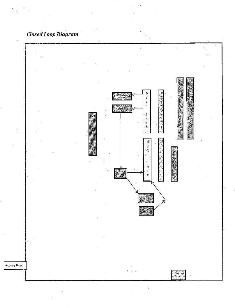
Closed Loop Diagram
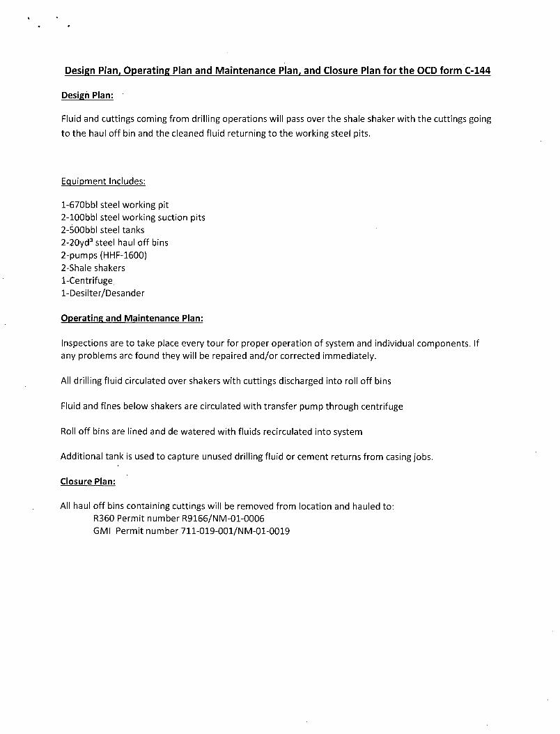
Design Plan, Operating Plan and Maintenance Plan, and Closure Plan for the OCD form C-144
Design Plan:
Fluid and cuttings coming from drilling operations will pass over the shale shaker with the cuttings going
to the haul off bin and the cleaned fluid returning to the working steel pits.
Equipment Includes:
1- 670bbl steel working pit 2- 100bbl steel working suction pits 2-500bbl steel tanks 2-20yd3 steel haul off bins 2-pumps(HHF-1600) 2-Shale shakers 1-Centrifuge 1-Desilter/Desander
Operating and Maintenance Plan:
Inspections are to take place every tour for proper operation of system and individual components. If any problems are found they will be repaired and/or corrected immediately.
All drilling fluid circulated over shakers with cuttings discharged into roll off bins
Fluid and fines below shakers are circulated with transfer pump through centrifuge
Roll off bins are lined and de watered with fluids recirculated into system
Additional tank is used to capture unused drilling fluid or cement returns from casing jobs.
Closure Plan:
All haul off bins containing cuttings will be removed from location and hauled to: R360 Permit number R9166/NM-01-0006 GMI Permit number 711-019-001/NM-01-0019


Murchison Oil and Gas 1100 Mira Vista Blvd, Piano, TX 75093
Murchison Oil and Gas
H2S Drilling Operations Plan
Nash Unit Fed Com #106H
Eddy County, New Mexico
Prepared by: Steve Morris Date: 07/23/2014

H2S Contingency Plan Section .3
Scope: 3
Objective: 3
Emergency Procedures Section 4
Emergency Procedures 4
Emergency Procedure Implementation 4
Simulated Blowout Control Drills 5
Ignition Procedures 8
Responsibility: 8
Instructions for Igniting the Well: 8
Training Program 9
Emergency Equipment Requirements : 9
CHECK LISTS .' 13
Status Check List 13
Procedural Check List 13
Briefing Procedures 14
Pre-Spud Meeting 14
Evacuation Plan 15
General Plan 15
Emergency Assistance Telephone List 15
MAPS AND PLATS 16
Page 2 of 16

H2S Contingency Plan Section
Scope:
This contingency plan provides an organized plan of action for alerting and protecting the public within an area of exposure prior to an intentional release, of following the accidental release of a potentially hazardous volume of hydrogen sulfide. The plan establishes'guidelines for all personnel whose work activity may involve exposure to Hydrogen Sulfide Gas (H2S).
Objective: Prevent any and all accidents, and prevent the uncontrolled release of H2S into the atmosphere.
Provide proper evacuation procedures to cope with emergencies.
Provide immediate and adequate medical attention should an injury occur.
Implementation: This plan, with all details, is to be fully implemented 1000' before drilling into the first sour zone.
Emergency Response Procedure: This section outlines the conditions and denotes steps to be taken in the event of an emergency. .
Emergency Equipment and Procedure: This section outlines the safety and emergency equipment that will be required for the drilling of this well.
Training Provisions: This section outlines the training provisions that must be adhered to 1000' before drilling into the first sour zone.
Emergency Call Lists: Included are the telephone numbers of ail persons that would need to be contacted, should an H2S emergency occur.
Briefing: This section deals with the briefing of all persons involved with the drilling of this well.
Public Safety: Public safety personnel will be made aware ofthe drilling of this well.
Check Lists: Status check lists and procedural check lists have been included to ensure adherence to the plan.
General Information: A general information section has been included to supply support information.
Page 3 of 16
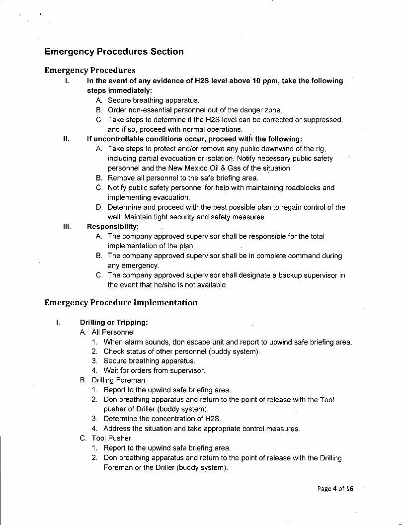
Emergency Procedures Section
Emergency Procedures I. In the event of any evidence of H2S level above 10 ppm, take the following
steps immediately: A. Secure breathing apparatus. B. Order non-essential personnel out of the danger zone. C. Take steps to determine if the H2S level can be corrected or suppressed,
and if so, proceed with normal operations. II. If uncontrollable conditions occur, proceed with the following:
A. Take steps to protect and/or remove any public downwind of the rig, including partial evacuation or isolation. Notify necessary public safety personnel and the New Mexico Oil & Gas of the situation.
B. Remove all personnel to the safe briefing area. C. Notify public safety personnel for help with maintaining roadblocks and
implementing evacuation. D. Determine and proceed with the best possible plan to regain control of the
well. Maintain tight security and safety measures. III. Responsibility:
A. The company approved supervisor shall be responsible for the total implementation of the plan.
B. The company approved supervisor shall be in complete command during any emergency.
C. The company approved supervisor shall designate a backup supervisor in the event that he/she is not available.
Emergency Procedure Implementation
I. Drilling or Tripping: A. All Personnel
1. When alarm sounds, don escape unit and report to upwind safe briefing area. 2. Check status of other personnel (buddy system). 3. Secure breathing apparatus. 4. Wait for orders from supervisor.
B. Drilling Foreman 1. Report to the upwind safe briefing area. 2. Don breathing apparatus and return to the point of release with the Tool
pusher of Driller (buddy system). 3. Determine the concentration of H2S. 4. Address the situation and take appropriate control measures.
C. Tool Pusher 1. Report to the upwind safe briefing area. 2. Don breathing apparatus and return to the point of release with the Drilling
Foreman or the Driller (buddy system).
Page 4 of 16

3. Determine the concentration. 4. Address the situation and take appropriate control measures.
D. Driller 1. Check the status of other personnel (in a rescue attempt, always use the
buddy system). 2. Assign the least essential person to notify the Drilling Foreman and Tool
Pusher, in the event of their absence. 3. Assume the responsibility of the Drilling Foreman and the Tool Pusher until
they arrive, in the event of their absence. E. Derrick Man and Floor Hands
1. Remain in the upwind safe briefing area until otherwise instructed by a supervisor.
F. Mud Engineer 1. Report to the upwind safe briefing area. 2. When instructed, begin check of mud for PH level and H2S level.
G. Safety Personnel 1. Don breathing apparatus. 2. Check the status of all personnel. 3. Wait for instructions from Drilling Foreman or Tool Pusher.
II. Taking a Kick: A. All personnel report to the upwind safe briefing area. B. Follow standard BOP procedures.
III. Open Hole Logging: A. All unnecessary personnel should leave the rig floor. B. Drilling Foreman and Safety personnel should monitor the conditions and make necessary safety equipment recommendations.
IV. Running Casing or Plugging: A. Follow "Drilling or Tripping" procedures. B. Assure that all personnel have access to protective equipment.
Simulated Blowout Control Drills All drills will be initiated by activating alarm devices (air horn). One long blast on the air horn for ACTUAL and SIMULATED blowout control drills. This operation will be performed by the Drilling Foreman or Tool Pusher at least one time per week for each of the following conditions, with each crew:
Drill #1 On-bottom Drilling
Drill #2 Tripping Drill Pipe
In each of these drills, the initial reaction time to shutting in the well shall be timed as well as the total time for the crew to complete its entire put drill assignment. The times must be recorded on the IADC Driller's log as "Blowout Control Drill".
Page 5 of 16

Drill No.: Reaction Time to Shut-in: minutes, seconds. Total Time to Complete Assignment: minutes, seconds.
I. Drill Overviews: A. Drill No. 1 - On-bottom Drilling
1. Sound the alarm immediately. 2. Stop the rotary and hoist the Kelly joint above the rotary table. 3. Stop the circulatory pump. 4. Close the drill pipe rams. 5. Record casing and drill pipe shut-in pressures and pit volume increases.
B. Drill No. 2 - Tripping Drill Pipe: 1. Sound the alarm immediately. 2. Position the upper tool joint just above the rotary table and set the slips. 3. Install a full opening valve inside blowout preventer tool in order to close
the drill pipe. 4. Close the drill pipe rams. 5. Record the shut-in annular pressure.
II. Crew Assignments A. Drill No. 1-On-bottom Drilling:
1. Driller a) Stop the rotary and hoist the Kelly joint above the rotary table. b) Stop the circulatory pump. c) Check flow. d) If flowing, sound the alarm immediately. e) Record the shut-in drill pipe pressure. f) Determine the mud weight increase needed or other courses of
action. 2. Derrick Man
a) Open choke line valve at BOP. b) Signal Floor Man #1 at accumulator that choke line is open. c) Close choke upstream valve after pipe rams have been closed. d) Read the shut-in annular pressure and report readings to Driller.
3. Floor Man #1 a) Close the pipe rams after receiving the signal from the Derrick Man. b) Report to Driller for further instructions.
4. Floor Man #2 a) Notify the Tool Pusher and Operator Representative of the H2S
alarms. b) Check for open fires and, if safe to do so, extinguish them. c) Stop all welding operations. d) Turn-off all non-explosive proof lights and instruments.
Page 6 of 16

e) Report to Driller for further instructions. 5. Tool Pusher
a) Report to the rig floor. b) Have a meeting with all crews. c) Compile and summarize all information. d) Calculate the proper kill weight. e) Ensure that proper well procedures are put into action.
6. Operator Representative a) Notify the Drilling Superintendent. b) Determine if an emergency exists and if so, activate the contingency
plan. Drill No. 2 - Tripping Pipe: 1. Driller
a) Sound the alarm immediately when mud volume increase has been detected.
b) Position the upper tool joint just above the rotary table and set slips. c) Install a full opening valve or inside blowout preventer tool to close the
drill pipe. d) Check flow. e) Record all data reported by the crew. f) Determine the course of action.
2. Derrick Man a) Come down out of derrick. b) Notify Tool Pusher and Operator Representative. c) Check for open fires and, if safe to do so, extinguish them. d) Stop all welding operations. e) Report to Driller for further instructions.
3. Floor Man #1 a) Pick up full opening valve or inside blowout preventer tool and slab
into tool join above rotary table (with Floor Man #2) b) Tighten valve with back-up tongs. c) Close pipe rams after signal from Floor Man #2. d) Read accumulator pressure and check for possible high pressure fluid
leaks in valves or piping. e) Report to Driller for further instructions.
4. Floor Man #2 a) Pick-up full opening valve or inside blowout preventer tool and tab into
tool joint above rotary table (with Floor Man #1) b) Position back-up tongs on drill pipe. c) Open choke line valve at BOP. d) Signal Floor Man #1 at accumulator that choke line is open. e) Close choke and upstream valve after pipe rams have been closed. f) Check for leaks on BOP stack and choke manifold.
Page 7 of 16

g) Read annular pressure. h) Report readings to the Driller.
5. Tool Pusher a) Report to the rig floor. b) Have a meeting with all of the crews. c) Compile and summarize all information. d) See that proper well kill procedures are put into action.
6. Operator Representative a) Notify Drilling Superintendent. b) Determine if an emergency exists, and if so, activate the contingency
plan
Ignition Procedures
Responsibility:
The decision to ignite the well is responsibility ofthe DRILLING FOREMAN in concurrence with the STATE POLICE. In the event ofthe Drilling Foreman is incapacitated, it becomes the responsibility ofthe RIG TOOL PUSHER. This decision should be made only as a last resort and in a situation where it is clear that:
1. Human life and property are endangered. 2. There is no hope of controlling the blowout under the prevailing conditions.
If time permits, notify the main office, but do not delay if human life is in danger. Initiate the first phase of the evacuation plan.
Instructions for Igniting the Well: 1. Two people are required for the actual igniting operation. Both men must wear self-
contained breathing apparatus and must use a full body harness and attach a retrievable safety line to the D-Ring in the back. One man must monitor the atmosphere for explosive gases with the LEL monitor, while the Drilling Foreman is responsible for igniting the well.
2. The primary method to ignite is a 25mm flare gun with a range of approximately 500 feet.
3. Ignite from upwind and do not approach any closer than is warranted. 4. Select the ignition site best suited for protection and which offers an easy escape route. 5. Before igniting, check for the presence of combustible gases. 6. After igniting, continue emergency actions and procedures.as before. 7. All unassigned personnel will limit their actions to those directed by the Drilling Foreman.
NOTE: After the well is ignited, burning Hydrogen Sulfide will convert to Sulfur Dioxide, which is also highly toxic. Do not assume the area is safe after the well is ignited.
Page 8 of 16

Training Program
When working in an area where Hydrogen Sulfide (H2S) might be encountered, definite training requirements for all personnel must be carried out. The Company Supervisor will ensure that all personnel at the well site have had adequate training in the following:
1. Hazards and Characteristics of Hydrogen Sulfide. 2. Physicals effects of Hydrogen Sulfide on the human body. 3. Toxicity of Hydrogen Sulfide and Sulfur Dioxide. 4. H2S detection, emergency alarm and sensor location. 5. Emergency rescue. 6. Resuscitators. 7. First aid and artificial resuscitation. 8. The effects of Hydrogen Sulfide on metals. 9. Location safety.
Service company personnel and visiting personnel must be notified if the zone contains H2S, and each service company must provide adequate training and equipment for their employees before they arrive at the well site.
Emergency Equipment Requirements
Lease Entrance Sign:
Should be located at the lease entrance with the following information:
CAUTION- POTENTIAL POISON GAS HYDROGEN SULFIDE
Well Control Equipment:
o A flare line will be located a minimum of 150' from the wellhead to be ignited by a flare gun.
» The choke manifold will include a remotely operated choke, o A mud/gas separator will be installed to separate gas from the drilling
mud.
Mud Program:
The drilling mud program has been designed to minimize the volume of hydrogen sulfide (H2S) circulated to surface. The operator will have the necessary mud products on location to minimize the hazards while drilling in H2S-bearing zones.
Page 9 of 16
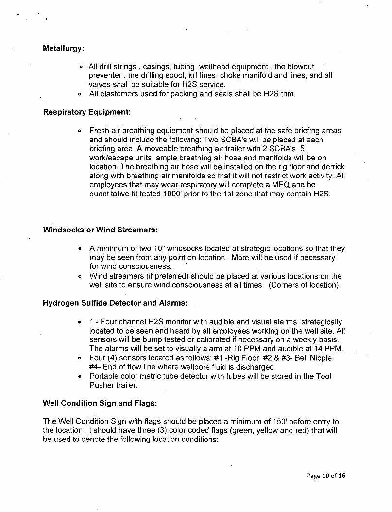
Metallurgy:
• All drill strings , casings, tubing, wellhead equipment, the blowout preventer, the drilling spool, kill lines, choke manifold and lines, and all valves shall be suitable for H2S service.
© All elastomers used for packing and seals shall be H2S trim.
Respiratory Equipment:
« Fresh air breathing equipment should be placed at the safe briefing areas and should include the following: Two SCBA's will be placed at each briefing area. A moveable breathing air trailer with 2 SCBA's, 5 work/escape units, ample breathing air hose and manifolds will be on location. The breathing air hose will be installed on the rig floor and derrick along with breathing air manifolds so that it will not restrict work activity. All employees that may wear respiratory will complete a MEQ and be quantitative fit tested 1000' prior to the 1st zone that may contain H2S.
Windsocks or Wind Streamers:
» A minimum of two 10" windsocks located at strategic locations so that they may be seen from any point on location. More will be used if necessary for wind consciousness.
® Wind streamers (if preferred) should be placed at various locations on the well site to ensure wind consciousness at all times. (Corners of location).
Hydrogen Sulfide Detector and Alarms:
* 1 - Four channel H2S monitor with audible and visual alarms, strategically located to be seen and heard by all employees working on the well site. All sensors will be bump tested or calibrated if necessary on a weekly basis. The alarms will be set to visually alarm at 10 PPM and audible at 14 PPM.
« Four (4) sensors located as follows: #1 -Rig Floor, #2 & #3- Bell Nipple, #4- End of flow line where wellbore fluid is discharged.
» Portable color metric tube detector with tubes will be stored in the Tool Pusher trailer.
Well Condition Sign and Flags:
The Well Condition Sign with flags should be placed a minimum of 150' before entry to the location. It should have three (3) color coded flags (green, yellow and red) that will be used to denote the following location conditions:
Page 10 of 16

GREEN - Normal Operating Conditions
YELLOW - Potential Danger
RED - Danger, H2S Gas Present
Auxiliary Rescue Equipment:
o Stretcher (drilling contractor) * 2-100' OSHA approved Rescue lines (drilling contractor) © First Aid Kit properly stocked (drilling contractor)
Mud Inspection Equipment:
Garret Gas Train or Hach Tester for inspection of Hydrogen Sulfide in the drilling mud system.
Fire Extinguishers:
Adequate fire extinguishers shall be located at strategic locations (provided by drilling contractor)
Blowout Preventer:
© The well shall have hydraulic BOP equipment for the anticipated BHP. © The BOP should be tested upon installation. © BOP, Choke Line and Kill Line will be tested as specified by Operator in
the drilling plan. The frequency is per Onshore regulations.
Confined Space Monitor:
There should be a portable multi-gas monitor with at least 3 sensors (02, LEL & H2S). This instrument should be used to test the atmosphere of any confined space before entering. It should also be used for atmospheric testing for LEL gas before beginning any type of Hot Work. Proper calibration documentation will need to be provided. (Supplied by Drilling Contractor)
Communication Equipment:
© Proper communication equipment such as cell phones or 2 -way radios should be available at the rig.
© Radio communication shall be available for communication between the company man's trailer, rig floor and the tool pusher's trailer.
© Communication equipment shall be available on the vehicles.
Page 11 of 16

Special Control Equipment:
» Hydraulic BOP equipment with remote control on the ground. • Rotating head at the surface casing point. » BOP, Choke Manifold and Process Flow Diagrams (see the attached -
previously submitted) ® Choke Manifold Equipment (see the attached - previously submitted)
Evacuation Plan:
o Evacuation routes should be established prior to spudding the well, e Should be discussed with all rig personnel.
Designated Areas:
Parking and Visitor area:
• All vehicles are to be parked at a pre-determined safe distance from the wellhead.
« Designated smoking area.
Safe Briefing Areas:
• Two safe briefing Areas shall be designated on either side of the location at the maximum allowable distance from the well bore so they offset prevailing winds or they are at a 180 degree angle if wind directions tend to shift in the area.
• Personal protective equipment should be stored at both briefing areas or if a moveable cascade trailer is used, it should be kept upwind of existing winds. When wind is from the prevailing direction, both briefing areas should be accessible.
NOTES:
• Additional equipment will be available at the Read and Stevens, Inc. Rowsell, New Mexico office.
• Additional personal H2S monitors are available for all employees on location, e Automatic Flare Igniters are recommended for installation on the rig.
Page 12 of 16

CHECK LISTS
Status Check List
Note: Date each item as they are implemented.
1. Sign at location entrance. 2. Two (2) wind socks (in required locations). 3. Wind Streamers (if required). 4. SCBA's on location for all rig personnel and mud loggers. 5. Air packs, inspected and ready for use. 6. Spare bottles for each air pack (if required). 7. Cascade system for refilling air bottles. 8. Cascade system and hose line hook up. 9. Choke manifold hooked-up and tested. (Before drilling out surface casing.) 10. Remote Hydraulic BOP control (hooked-up and tested before drilling out
surface casing). 11. BOP tested (before drilling out surface casing). 12. Mud engineer on location with equipment to test mud for H2S. 13. Safe Briefing Areas set-up. 14. Well Condition sign and flags on location and ready. 15. Hydrogen Sulfide detection system hooked-up & tested. 16. Hydrogen Sulfide alarm system hooked-up & tested. 17. Stretcher on location at Safe Briefing Area. 18.2-100' OSHA Approved Life Lines on location. .19.1 -20# Fire Extinguisher in safety trailer. 20. Confined Space Monitor on location and tested. 21 .All rig crews and supervisor trained (as required). 22. Access restricted for unauthorized personnel. 23. Drills on H2S and well control procedures. 24. All outside service contractors advised of potential H2S on the well. 25. NO SMOKING sign posted. 26. H2S Detector Pump w/tubes on location. 27.25mm Flare Gun on location w/flares. 28. Automatic Flare Igniter installed on rig.
Procedural Check List
Perform the following on each tour:
1. Check fire extinguishers to see that they have the proper charge. 2. Check breathing equipment to insure that they have not been tampered with. 3. Check pressure on the supply air bottles to make sure they are capable of
recharging. 4. Make sure all of the Hydrogen Sulfide detection systems are operative.
Page 13 of
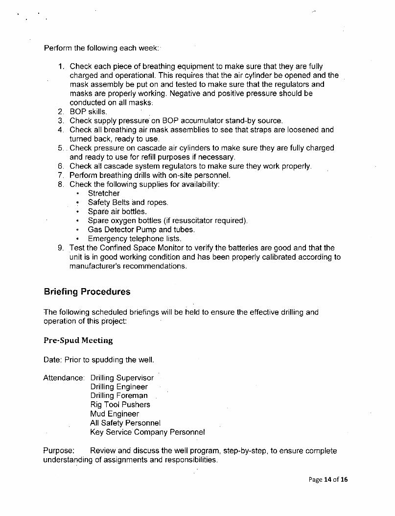
Perform the following each week:
1. Check each piece of breathing equipment to make sure that they are fully charged and operational. This requires that the air cylinder be opened and the mask assembly be put on and tested to make sure that the regulators and masks are properly working. Negative and positive pressure should be conducted on all masks.
2. BOP skills. 3. Check supply pressure on BOP accumulator stand-by source. 4. Check all breathing air mask assemblies to see that straps are loosened and
turned back, ready to use. 5. Check pressure on cascade air cylinders to make sure they are fully charged
and ready to use for refill purposes if necessary. 6. Check all cascade system regulators to make sure they work properly. 7. Perform breathing drills with on-site personnel. 8. Check the following supplies for availability:
• Stretcher • Safety Belts and ropes. • Spare air bottles. • Spare oxygen bottles (if resuscitator required). • Gas Detector Pump and tubes. • Emergency telephone lists.
9. Test the Confined Space Monitor to verify the batteries are good and that the unit is in good working condition and has been properly calibrated according to manufacturer's recommendations.
Briefing Procedures
The following scheduled briefings will be held to ensure the effective drilling and operation of this project:
Pre-Spud Meeting
Date: Prior to spudding the well.
Attendance: Drilling Supervisor Drilling Engineer Drilling Foreman Rig Tool Pushers Mud Engineer All Safety Personnel Key Service Company Personnel
Purpose: Review and discuss the well program, step-by-step, to ensure complete understanding of assignments and responsibilities.
Page 14 of 16
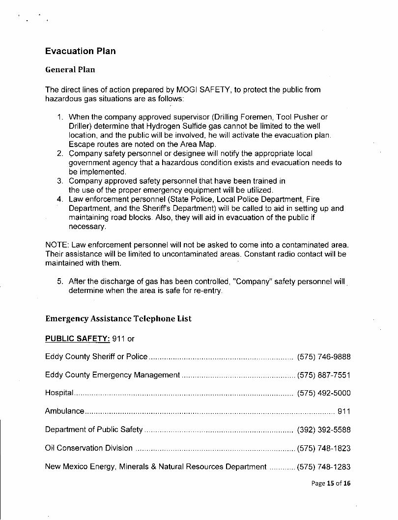
Evacuation Plan
General Plan
The direct lines of action prepared by MOGI SAFETY, to protect the public from hazardous gas situations are as follows:
1. When the company approved supervisor (Drilling Foremen, Tool Pusher or Driller) determine that Hydrogen Sulfide gas cannot be limited to the well location, and the public will be involved, he will activate the evacuation plan. Escape routes are noted on the Area Map.
2. Company safety personnel or designee will notify the appropriate local government agency that a hazardous condition exists and evacuation needs to be implemented.
3. Company approved safety personnel that have been trained in the use of the proper emergency equipment will be utilized.
4. Law enforcement personnel (State Police, Local Police Department, Fire Department, and the Sheriffs Department) will be called to aid in setting up and maintaining road blocks. Also, they will aid in evacuation ofthe public if necessary.
NOTE: Law enforcement personnel will not be asked to come into a contaminated area. Their assistance will be limited to uncontaminated areas. Constant radio contact will be maintained with them.
5. After the discharge of gas has been controlled, "Company" safety personnel will determine when the area is safe for re-entry.
Emergency Assistance Telephone List
PUBLIC SAFETY: 911 or
Eddy County Sheriff or Police (575) 746-9888
Eddy County Emergency Management (575) 887-7551
Hospital (575) 492-5000
Ambulance 911
Department of Public Safety (392) 392-5588
Oil Conservation Division (575) 748-1823
New Mexico Energy, Minerals & Natural Resources Department (575) 748-1283
Page 15 of 16
MOGI Emergnecy Call List:
Jack Rankin (713) 582-3859
Greg Boans (575) 706-0667
Joel Stockford (972) 835-3349
Steve Morris (972) 835-3315
The geologic zones that will be encountered during drilling may contain hazardous quantities of H2S. The accompanying map illustrates the affected areas ofthe community. The residents within this radius will be notified via a hand delivered written notice describing the activities, potential hazards, and conditions of evacuation, evacuation drill siren alarms and other precautionary measures.
Evacuee Description:
Residents: THERE ARE NO RESIDENTS WITHIN 3000' ROE.
Notification Process:
A continuous siren audible to all residence will be activated, signaling evacuation of previously notified and informed residents.
Evacuation Plan:
All evacuees will migrate laterally toward the wind direction.
Murchison Oil and Gas will identify all home bound or highly susceptible individuals and make special evacuation preparations, interfacing with the local and emergency medical service as necessary.
MAPS AND PLATS
See the attached map showing the 3000' ROE clarification.
Page 16 of 16
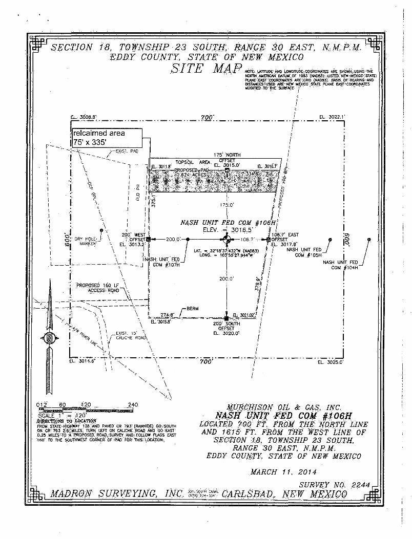
SECTION 18, TOWNSHIP 23 SOUTH, RANGE 30 EAST, N.M.P.M. EDDY COUNTY, STATE OF NEW MEXICO
BITE MAP
£ L 3008.3 ' 700'
NOTE: UOTRIDE .AND LONGITUDE COORD'.NATES ARE SHOWN;. USING "THE NORTH'AMERICAN DATUM;.0F 1983"(NADB3): ,USTED;'NEW.;MEXIC0 !;STATE: PLANE;EAST COORDINATES ARE GRID (NAD83). BASIS OF BEARING AND DISTANCES*USEO ARE NEW MEXICO STATE PLANE EAST'COORDINATES MODIFIED TO THE SURFACE j " " ' '
EL. 3 0 2 2 . 1 '
relcaimed area 75'x 335'
1 EL. 3011.8"
I ^ f-1 »
NASH'. UNIT FED COM # 1 0 7 H "
I
TOPSOIL AREA
175' NORTH "OFFSET"
EL 3015.0' PROPOSEDrPAD=—«=-B <-=-
, 2 624 ACRES, V T . 334 6 \ . ,<« '' 1
EL 3016.7'
II
1 75 :0 '
NASH UNIT FED COM §106H] ELEV. 4 3016.5'' | /.
j 106.7' EAST 200.0'—? — B ^ » — T 0 6 ; ' 7 ' - ^ - » « | O F F S E T .
T E L . 3017.8' J / NASH UNIT FED
/ t COM jjl105H LAT. - 32'18'37;432"N (NAD83)
LONG. = 103"5S'27.944"W J
274:8 ' r BERM
NASH UNIT FED COM # 1 0 4 H "
700' .J
EL. 3025.0 '
SCALE 1" •= ,T20' DIRECTIONS TO LOCATION FROM STATE HIGHWAY 128 'AND PAVED CR 793' (RAWHIDE), GO.;SOUTH ON CR 793 2.6- MILES; TURN LEFT ON CALICHE ROAD AND GO EAST 0.25.MlLES :T0 A'PROPOSED!" ROAD f" S U RVEY AN D •:•' FOLLOW FLAGS ;EAST 160' TO THE SOUTHWEST CORNER CF PAD FOR TH S LOCATION.
MURCHISON OIL & GAS, INC. NASH UNIT FED COM #106H
LOCATED 700 FT. FROM THE NORTH LINE AND 1615 FT. FROM THE WEST LINE OF
SECTION 1.8, TOWNSHIP 23 SOUTH, RANGE 30 EAST, N.M.P.M.
EDDY COUNTY, STATE OF NEW MEXICO
MARCH 11, 2014
SURVEY NO. 2244 ^ MADRON SURVEYING, INC. CARLSBAD, NEW MEXICO

Murchison Oil and Gas
e. No ATV's are to be used.
20. Maps and Diagrams a. Land Survey Plat b. Wells Within One Mile Radius of the PSHL and PBHL c. Well Site Diagram d. Interim Reclamation Plat e. Rig Layout Diagram f. Closed Loop Diagram
Page 10 of 10

Murchison Oil and Gas
Surface Use Plan of Operations
Introduction The following surface use plan of operations will be followed and carried out once the APD is approved. No other disturbance will be created other than what was submitted in this surface use plan. If any other surface disturbances is needed after the APD is approved, a BLM approved sundry notice or right of way application will be acquired prior to any new surface disturbances.
Before any surface disturbance is created, stakes or flagging will be installed to mark boundaries of permitted areas of disturbance, inlcuding soils storage areas. As necessary, slope, grade, and other constuction control stakes will be placed to ensure consruction in accordance with the surface use plan. All boundary markers will be maintained in place until final construction cleanip is completed. If disturbance boundary markers are disturbed or knocked down, they will be replaced before construction proceeds.
If terms and conditions are attahced to the apporoved APD and amend any of the prosed actions in this surface use plan, we will adhere to the terms and conditions.
1. Construction a. Notification
The BLM shall administer compliance and monitor construction of the access road and well pad. Notify the Carlsbad Field Office at (575) 234-5909 at least 3 working days prior to commencing construction ofthe access road and/or well pad.
b. Topsoil The operator shall strip the top portion of the soil (root zone) from the entire well pad area and stockpile the topsoil along the edge of the well pas as depicted in the APD. The root zone is typically six (6) inched in depth. All the stockpiled topsoil will be redistributed over the interim reclamation areas. Topsoil shall not be used for berming the pa or facilities. For final reclamation, the topsoil shall spread over the entire pad area for seeding preparation.
Other subsoil (below six inches) stockpiles must be completely segregated from the topsoil stockpile. Large rocks or subsoil clods (not evident in the surrounding terrain) must be buried within the approved area for interim and final reclamation,
2. Existing Roads a. The existing access road route to the proposed project is depicted on Land Survey
Plat. A new road will be routed to the Nash Unit Fed Com 107H as per the attached plat. Improvements to the driving surface will be done where necessary. No new surface disturbance will be done, unless otherwise noted in the New or Reconstructed Access Roads sections of this surface plan.
Page 1 of 10

Murchison Oil and Gas
b. The Existing access road route to the proposed project does not cross lease or unit boundaries, so a BLM right-of -way grant will not be acquired for this proposed road route.
c. Existing oil and gas roads utilized top access the proposed project.will be maintained be crowning, clearing ditches, and fixing potholes. All existing structures on the entire access route such as cattleguards, other range improvement projects, culverts etc. will be properly repaired or replaced if they are damaged or have deteriorated beyond practical use.
d. The access road shall have a driving surface that creates the smallest possible surface disturbance and does not exceed fourteen (14) feet in width. The maximum width of surface disturbance, when constructing the access road, shall not exceed twenty-five (25) feet.
e. Surfacing material is not required on the new access road driving surface. If the operator elects to surface the new access road or pad, the Surfacing material may be required to be removed at the time of reclamation.
f. Where possible, no improvements should be made on the unsurfaced access road other than to remove vegetation as necessary, road irregularities, safety issue, or to fill low areas that may sustain standing water.
g. The Authorized Officer reserves the right to require surfacing of any portion of the access road at any time deemed necessary. Surfacing may be required in the even the road deteriorates, erodes, road traffic increase, or it is determined to be beneficial for future field development. The surfacing depth and type of material will be determined at the time of notification.
h. Crowning shall be done on the access road driving surface. The road crown shall have a grade of approximately 2% (i.e., a 14' wide road). The road shall conform to figure 1; cross section and plans for typical road construction.
i. Ditching shall be required on both sides of the road j . Vehicle turnouts shall be constructed on the road. Turnouts shall be constructed on
all blind curves. Turnouts shall conform to the following diagram: Standard Turnout - Plan View
14'
IN. 1 10'
25' 50' 25'
k. Drainage control systems shall be constructed on the entire length of road (e.g. ditches, side hill, out-sloping, and in-sloping, lead-off ditches, culvert installation, and low water crossing). A typical lead-off ditch has a minimum depth of 1 foot below and berm of 6 inches above natural ground level. The berm shall be on the down-slop side of the lead-off ditch.
All lead-off ditches shall be graded to drain water with a 1 percent minimum to 3 percent maximum ditch slope. The spacing interval are variable for lead-off ditches ad shall be
Page 2 of 10

Murchison Oil and Gas
determined according to the formula for spacing intervals of lead-off ditches, but may be amended depending upon existing sol types and centerline road slope (in %);
Cross Section of a Typical Lead off Ditch
Natural ground level
Slope Side
Formula for Spacing Interval of Lead-off Ditches
Example - on a 4% road slope that is 400 feet long, the water flow shall drain water into a lead-off ditch. Spacing intervals shall be determined by the following formula:
400 foot road with 4% road slope: — + 100' = 200' lead-off ditch interval
3. New or Reconstructed Access Roads a. The existing road will be used and a new road will be constructed from that pad and
routed to the south west side of the drill pad to the existing road. BLM rep has approved the routing.
Page 3 of 10

Murchison Oil and Gas
Cross Sections and Plans for Typical Road Sections
rT*-'-V. "* T " ^ . ^ turnout ,1 CT'
.25* . . I S ' , .
Typicia i : Turnout Plan:
Alt tSof$o losA rapes' on c3 bCn<S curtail !
ad&fo f fb t Itmoats'w n«b&«f io- l««p i p o r f o g : bnfc~ 1000 Tool.
4. Location of Existing Wells a. A 1 mile radius map has been attached with the APD.
5. Location of Existing and/or Proposed Production Facilities a. All permanent, lasting more than 6 months, above ground structures including but
not limited to pumpjacks, storage tanks, barrels, pipeline risers, meter housing, etc. That are not subject to safety requirements will be painted a non-reflective paint floor that blends in with the surrounding landscape. The paint color will be one of the colors from the BLM Standard Environmental Colors chart selected by the BLM authorized officer.
Page 4 of 10

Murchison Oil and Gas
b. All proposed production facilities that are located on the well pad will be strategically placed to allow for maximum interim reclamation, recontouring, and revegetation of the well location.
c. Production from the proposed well will be contained on an onsite battery. See attached drawing included with APD.
d. A pipeline to transport production will be installed from the proposed well to the battery
i. We plan to install a 2,875 inch Steel (tubing) pipeline below surface from the proposed well to the production facility. The maximum working pressure of the pipeline will be 7,260 psi; however we will not operate this pipeline at an internal pressure in excess of 250 psi.
ii. Attached drawing depicts the proposed production pipeline route from the well to the production facility.
iii. The proposed pipeline will be below surface. e. If any plans change regarding the production facility or other infrastructure (pipeline,
electric line, etc.), we will submit a sundry notice or right of way (if applicable) prior to installation of construction.
f. An electric line will be applied for through a sundry notice or BLM right-of-way at a later date.
6. Location and Types of Water a. The source and location of the water supply are as follows: The well will be drilled
with a combination of fresh water and brine water based mud systems. The water will be obtained from commercial suppliers in the area and/or piped or hauled to the location by transport trucks over an existing road. Any temporary pipelines for transfer of water will be installed along existing roads and removed within one week following the final use of such pipelines.
7. Construction Materials a. Construction material that will be used to build the well pad and road will be caliche. b. All material required for construction of the drill pad and access roads will be
obtained from private, state, or federal pits, if the well pad is flipped to acquire caliche underneath the well pad, Operator shall stay within the approved well pad area when performing these operations. A federal mineral material permit will be acquired prior to flipping the location for caliche or acquiring caliche from a federal pit.
8. Methods of Handling Waste a. Drilling fluids and produced oil and water from the well during completion operations
will be stored safely and disposed of properly in an NMOCD-approved disposal facility.
Page 5 of 10

Murchison Oil and Gas
b. Garbage and trash produced during drilling and completion operations will be collected in a trash bin and disposed of properly at a state approved site. All trash on and around the well site will be collected for disposal.
c. Human waste and grey water will be properly contained and disposed of properly at a disposal facility.
d. After drilling and completion operations, trash, chemicals, salts, frac sand and other waste material will be removed and disposed of properly at a disposal site.
e. The well will be drilled utilizing a closed loop system. Drill cuttings will be properly disposed of into steel tanks and taken to an NMCOD-approved disposal facility.
9. Ancillary facilities a. No ancillary facilities will be needed for this proposed project.
10. Weil Site Layout a. The proposed drilling pad was staked and surveyed by a professional surveyor. The
attached survey plat of the well site depicts the drilling pad layout as staked. b. Attached are rig layout and a site layout diagrams. c. Topsoil Salvaging:
Grass, forbs, and small woody vegetation, such as sagebrush will be excavated as the topsoil is removed. Large woody vegetation will be stripped and stored separately and respread evenly on the site following topsoil respreading. Topsoil depth is defined as the top layer of soil that contains 80% ofthe roots. In areas to be heavily disturbed, the top 6 inches of soil material will be stripped and stockpiled on the perimeter of the well location and along the perimeter of the access road to control run-on and run-off, to keep topsoil viable, and to make redistribution of topsoil more efficient during interim reclamation. Stockpiled topsoil should include vegetative material. Topsoil will be clearly segregated and stored separately from subsoils. Contaminated soil will not be stockpiled, but properly treated and handled prior to topsoil salvaging.
11. Plans for Surface Reclamation a. Reclamation Objectives:
i. The objective of interim reclamation is to restore vegetative cover and a portion of the landform sufficient to maintain healthy, biologically active topsoil; control erosion; and minimize habitat and forage loss, visual impact, and weed infestation, during the life ofthe well or facilities.
ii. The long-term objective of final reclamation is to return the land to a condition approximating that which existed prior to disturbance. This includes restoration of the landform and natural vegetative community, hydrologic systems, visual resources, and wildlife habitats. To ensure that the long-term objective will be reached through human and natural processes, actions will be taken to ensure standards are met for site stability, visual quality, hydrological functioning, and vegetative productivity
Page 6 of 10

Murchison Oil and Gas
iii. The BLM will be notified at least 3 days prior to commencement of any reclamation procedures.
iv. If circumstances allow, interim reclamation and/or final reclamation actions will be completed no later than 6 months from when the final well on the location has been completed or plugged. We will request written permission from the BLM if more time is needed.
b. Interim Reclamation i. Interim reclamation will be performed on the well site after the last well planned
on this location, has been drilled and completed. An interim reclamation plat is attached.
ii. Within 30 days of well completion, the well location and surrounding areas will be cleared of, and maintained free of, all materials, trash, and equipment not required for production.
iii. In areas planned for interim reclamation, all the surfacing material will be removed and returned to the original mineral pit or recycled to repair or build roads and well pads.
iv. The areas planned for interim reclamation will then be recontourned to the original contour if feasible, or if not feasible, to an interim contour that blends with the surrounding topography as much as possible. Where applicable, the fill material of the well pad will be backfilled into the cut to bring the area back to the original contour. The interim cut and fill slopes prior to re-seeding will not be steeper than a 3:1 ratio, unless the adjacent native topography is steeper. Note: Constructed slopes may be much steeper during drilling, but will be recontourned to above ratios during interim reclamation.
v. Topsoil will be evenly respread and aggressively revegetated over the entire disturbed area not needed for all-weather operations including cuts & fills. To seed the area, the proper BLM seed mixture, free of noxious weeds, will be used. Final seedbed preparation will consist of contour cultivating to a depth of 4 to 6 inches within 24 hours prior to seeding, dozer tracking, or other imprinting in order to break the soil crust and create seed germination micro-sites.
vi. Proper erosion control methods will be used on the area to control erosion, runoff and siltation of the surrounding area.
vii. The interim reclamation will be monitored periodically to ensure that vegetation has reestablished and that erosion is controlled.
c. Final Reclamation (well pad, buried pipelines, etc.) i. Prior to final reclamation procedures, the well pad, road, and surrounding area
will be cleared of material, trash, and equipment. ii. All surfacing material will be removed and returned to the original mineral pit or
recycled to repair or build roads and well pads. iii. All disturbed areas, including roads, pipelines, pads, production facilities, and
interim reclaimed areas will be recontoured to the contour existing prior to initial construction or a contour that blends indistinguishably with the surrounding landscape. Topsoil that was spread over the interim reclamation
Page 7 of 10
Murchison Oil and Gas
areas will be stockpiled prior to recontouring. The topsoil will be redistributed evenly over the entire disturbed site to ensure successful revegetation.
iv. After all the disturbed areas have been properly prepared, the areas will be seeded with the proper BLM seed mixture, free of noxious weeds. Final seedbed preparation will consist of contour cultivating to a depth of 4 to 6 inches within 24 hours prior to seeding, dozer tracking, or other imprinting in order to break the soil crust and create seed germination micro-sites.
v. Proper erosion control methods will be used on the entire area to control erosion, runoff and siltation ofthe surrounding area.
vi. All unused equipment and structures including pipelines, electric line poles, tanks, etc. that serviced the well will be removed.
vii. All reclaimed areas will be monitored periodically to ensure that revegetation occurs, that the area is not redisturbed, and that erosion is controlled.
12. Federal Mineral Materials Pit Payment shall be made to the BLM prior to removal of any federal mineral materials. Call the Carlsbad Field Office at (575) 234-5972
13. Well Pad Surfacing Surfacing of the well pad is required.
If the Operator elects to surface the well pad, the surfacing material may be required to be removed at the time of reclamation.
The well pad shall be constructed in a manner which creates the smallest possible surface disturbance, consistent with safety and operational needs.
14. Enclosure Fencing (Cellars & Pits) Enclosure Fencing The operator will install and maintain enclosure fencing for all open well cellars to prevent access to public, livestock, and large forms of wildlife before and after drilling operations until the pit is free of fluids and the operator initiates backfilling. (For examples of enclosure fencing design, refer to BLM's Oil and Gas Gold Book, Enclosure Fence Illustrations, Figure 1, Page 18.)
15. On Lease Access Roads Cattle guards An appropriately sized cattle guard(s) sufficient to carry out the project shall be installed and maintained at fence crossing(s)
Any existing cattle guard(s) on the access road shall be repaired or replaced if they are damaged or have deteriorated beyond practical use. The operator shall be responsible for the condition of the existing cattle guard(s) that are in place and are utilized during lease operations.
A gate shall be constructed and fastened securely to H-braces.
Page 8 of 10

Murchison Oil and Gas
Fence Requirement
Where entry is required across a fence line, the fence shall be braced and tied off on both sides of the passageway prior to cutting.
The operator shall notify the private surface landowner or the grazing allotment holder prior to crossing any fence(s).
16. Surface Ownership a. The surface ownership ofthe proposed project is federal.
Surface Owner: J. Mobley 3515 Standpipe road, Carlsbad NM 88220 b. A surface use agreement was obtained from the surface tennant regarding the
proposed project. c. A good faith effort will be made to provide a copy of the APD Surface Use Plan of
Operations to the private surface owner.
17. Archaeological, Paleontology & Historical Sites Any cultural and/or paleontological resource discovered by operator or by any person working on the operator's behalf shall immediately report such findings to the Authorized Officer. The operator is fully accountable for the actions of their contractors and subcontractors. The operator shall suspend all operations in the immediate area of such discovery until written authorization to proceed is issued by the Authorized Officer. An evaluation of the discovery shall be made by the Authorized Officer to determine the appropriate actions that shall be required to prevent the loss of significant cultural or scientific values of the discovery. The operator shall be held responsible for the cost of the proper mitigation measures that the Authorized Officer assesses after consultation with the operator on the evaluation and decisions of the discovery. Any unauthorized collection or disturbance of cultural or paleontological resources may result in a shutdown order by the Authorized Officer.
18. Noxious Weeds The operator shall be held responsible if noxious weeds become established within the areas of operations. Weed control shall be required on the disturbed land where noxious weeds exist, which includes the roads, pads, associated pipeline corridor, and adjacent land affected by the establishment of weed due to this action. The operator shall consult with the Authorized Officer for acceptable weed control methods, which include following EPA and BLM requirements and policies.
19. Special Requirements a. Locations and facilities will be 600' from the shorelines. b. From May 1 - August 31 there will be no drilling or completion operations unless the
recorded sound levels at 30' from the location are less than 49db. c. No power poles will be used, all power lines will be buried. d. No pits are to be used.
Page 9 of 10

urchison Oil and Gas
e. No ATV's are to be used.
20. Maps and Diagrams a. Land Survey Plat b. Wells Within One Mile Radius of the PSHL and PBHL c. Well Site Diagram d. Interim Reclamation Plat e. Rig Layout Diagram f. Closed Loop Diagram
Page 10 of 10
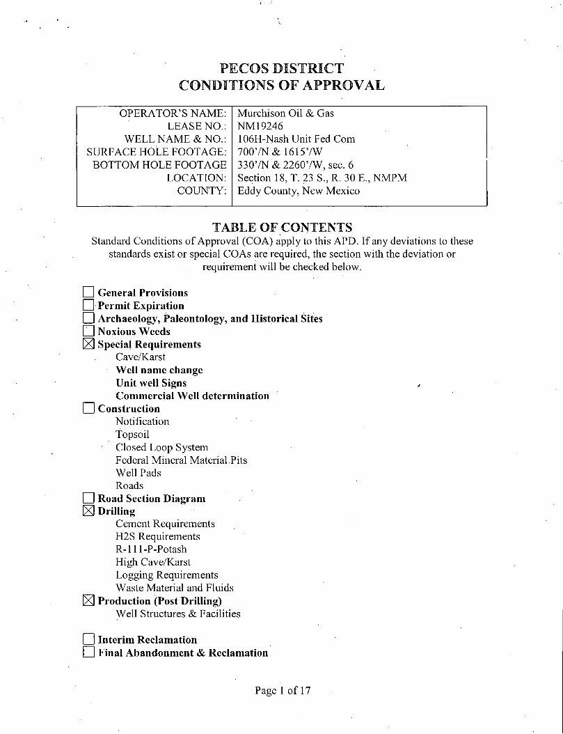
V
PECOS DISTRICT CONDITIONS OF APPROVAL
OPERATOR'S NAME: Murchison Oil & Gas LEASE NO.: NM 19246
WELL NAME & NO.: 106H-Nash Unit Fed Com SURFACE HOLE FOOTAGE: 7007N& 16157W BOTTOM HOLE FOOTAGE 3307N & 22607W, sec. 6
LOCATION: Section 18, T. 23 S., R. 30 E., NMPM COUNTY: Eddy County, New Mexico
T A B L E OF CONTENTS Standard Conditions of Approval (COA) apply to this APD. If any deviations to these
standards exist or special COAs are required, the section with the deviation or requirement will be checked below.
I I General Provisions CD Permit Expiration I I Archaeology, Paleontology, and Historical Sites P~l Noxious Weeds K Special Requirements
Cave/Karst Well name change Unit well Signs Commercial Well determination
I I Construction Notification Topsoil Closed Loop System Federal Mineral Material Pits Well Pads Roads
I I Road Section Diagram Kl Drilling
Cement Requirements H2S Requirements R-lll-P-Potash High Cave/Karst Logging Requirements Waste Material and Fluids
X] Production (Post Drilling) Well Structures & Facilities
I I Interim Reclamation Final Abandonment & Reclamation
Page 1 of 17

I. GENERAL PROVISIONS
The approval of the Application For Permit To Drill (APD) is in compliance with all applicable laws and regulations: 43 Code of Federal Regulations 3160, the lease terms, Onshore Oil and Gas Orders, Notices To Lessees, New Mexico Oil Conservation Division (NMOCD) Rules, National Historical Preservation Act As Amended, and instructions and orders of the Authorized Officer. Any request for a variance shall be submitted to the Authorized Officer on Form 3160-5, Sundry Notices and Report on Wells.
II. PERMIT EXPIRATION
If the permit terminates prior to drilling and drilling cannot be commenced within 60 days after expiration, an operator is required to submit Form 3160-5, Sundry Notices and Reports on Wells, requesting surface reclamation requirements for any surface disturbance. However, i f the operator will be able to initiate drilling within 60 days after the expiration of the permit, the operator must have set the conductor pipe in order to allow for an extension of 60 days beyond the expiration date of the APD. (Filing of a Sundry Notice is required for this 60 day extension.)
III. ARCHAEOLOGICAL, PALEONTOLOGY & HISTORICAL SITES
Any cultural and/or paleontological resource discovered by the operator or by any person working on the operator's behalf shall immediately report such findings to the Authorized Officer. The operator is fully accountable for the actions of their contractors and subcontractors. The operator shall suspend all operations in the immediate area of such discovery until written authorization to proceed is issued by the Authorized Officer. An evaluation of the discovery shall be made by the Authorized Officer to determine the appropriate actions that shall be required to prevent the loss of significant cultural or scientific values of the discovery. The operator shall be held responsible for the cost of the proper mitigation measures that the Authorized Officer assesses after consultation with the operator on the evaluation and decisions of the discovery. Any unauthorized collection or disturbance of cultural or paleontological resources may result in a shutdown order by the Authorized Officer.
I V NOXIOUS WEEDS •
The operator shall be held responsible if noxious weeds become established within the areas of operations. Weed control shall be required on the disturbed land where noxious weeds exist, which includes the roads, pads, associated pipeline corridor, and adjacent land affected by the establishment of weeds due to this action. The operator shall consult with the Authorized Officer for acceptable weed control methods, which include following EPA and BLM requirements and policies.
Page 2 of 17

V. SPECIAL REQUIREMENT(S)
Cave and Karst
Depending on location, additional Drilling, Casing, and Cementing procedures may be required by engineering to protect critical karst groundwater recharge areas.
Cave/Karst Surface Mitigation The following stipulations will be applied to minimize impacts during construction, drilling and production.
Construction: In the advent that any underground voids are opened up during construction activities, construction activities will be halted and the BLM will be notified immediately.
No Blasting: No blasting will be utilized for pad construction. The pad will be constructed and leveled by adding the necessary fil l and caliche.
Pad Berming: The entire perimeter of the well pad will be bermed to prevent oil, salt, and other chemical contaminants from leaving the well pad. o The compacted berm shall be constructed at a minimum of 12 inches high with
impermeable mineral material (e.g. caliche), o No water flow from the uphill side(s) of the pad shall be allowed to enter the well
pad. • The topsoil stockpile shall be located outside the bermed well pad. » Topsoil, either from the well pad or surrounding area, shall not be used to construct,
the berm. o No storm drains, tubing or openings shall be placed in the berm. o If fluid collects within the bermed area, the fluid must be vacuumed into a safe
container and disposed of properly at a state approved facility, o The integrity of the berm shall be maintained around the surfaced pad throughout the
life of the well and around the downsized pad after interim reclamation has been completed.
o Any access road entering the well pad shall be constructed so that the integrity of the berm height surrounding the well pad is not compromised. (Any access road crossing the berm cannot be lower than the berm height.)
Tank Battery Liners and Berms: Tank battery locations and all facilities will be lined and bermed. A 20 mil permanent liner will be installed with a 4 oz. felt backing to prevent tears or punctures. Tank battery berms must be large enough to contain 1 Vi times the content of the largest tank.
Leak Detection System:
Page 3 of 17

A method of detecting leaks is required. The method could incorporate gauges to measure loss, situating values and lines so they can be visually inspected, or installing electronic sensors to alarm when a leak is present. Leak detection plan will be submitted to BLM for approval.
Automatic Shut-off Systems: Automatic shut off, check values, or similar systems will be installed for pipelines and tanks to minimize the effects of catastrophic line failures used in production or drilling.
Cave/Karst Subsurface Mitigation The following stipulations will be applied to protect cave/karst and ground water concerns:
Rotary Drilling with Fresh Water: Fresh water will be used as a circulating medium in zones where caves or karst features are expected. SEE ALSO: Drilling COAs for this well.
Directional Drilling: Kick off for directional drilling will occur at least 100 feet below the bottom of the cave occurrence zone. SEE ALSO: Drilling COAs for this well.
Lost Circulation: ALL lost circulation zones from the surface to the base of the cave occurrence zone will be logged and reported in the drilling report.
Regardless of the type of drilling machinery used, i f a void of four feet or more and circulation losses greater than 70 percent occur simultaneously while drilling in any cave-bearing zone, the BLM will be notified immediately by the operator. The BLM will assess the situation and work with the operator on corrective actions to resolve the problem.
Abandonment Cementing: Upon well abandonment in high cave karst areas additional plugging conditions of approval may be required. The BLM will assess the situation and work with the operator to ensure proper plugging of the wellbore.
Pressure Testing: Annual pressure monitoring will be performed by the operator on all casing annuli and reported in a sundry notice. If the test results indicated a casing failure has occurred, remedial action will be undertaken to correct the problem to the BLM's approval.
Well Name Change
NOTE: this is a Unit well, a Communitization Agreement will not be required. The operator will attempt to establish a Participating Area via a Commercial Well
Page 4 of 17

Determination. Operator to submit a sundry after the well is completed to remove "Fed Com" from the well name.
Commercial Well Determination After 6 months of continuous production a commercial well determination will need to be submitted.
Unit Wells The well sign for a unit well shall include the unit number in addition to the surface and bottom hole lease numbers. This also applies to participating area numbers. If a participating area has not been established, the operator can use the general unit . designation, but will replace the unit number with the participating area number when the sign is replaced.
Page 5 of 17

VI. CONSTRUCTION
A. NOTIFICATION
The BLM shall administer compliance and monitor construction of the access road and well pad. Notify the Carlsbad Field Office at (575) 234-5909 at least 3 working days prior to commencing construction of the access road and/or well pad.
When construction operations are being conducted on this well, the operator shall have the approved APD and Conditions of Approval (COA) on the well site and they shall be made available upon request by the Authorized Officer.
B. TOPSOIL
The operator shall strip the top portion ofthe soil (root zone) from the entire well pad area and stockpile the topsoil along the edge of the well pad as depicted in the APD. The root zone is typically six (6) inches in depth. All the stockpiled topsoil will be redistributed over the interim reclamation areas. Topsoil shall not be used for benning the pad or facilities. For final reclamation, the topsoil shall be spread over the entire pad area for seeding preparation.
Other subsoil (below six inches) stockpiles must be completely segregated from the topsoil stockpile. Large rocks or subsoil clods (not evident in the surrounding terrain) must be buried within the approved area for interim and final reclamation.
C. CLOSED LOOP SYSTEM
Tanks are required for drilling operations: No Pits.
The operator shall properly dispose of drilling contents at an authorized disposal site.
D. FEDERAL MINERAL MATERIALS PIT
Payment shall be made to the BLM prior to removal of any federal mineral materials. Call the Carlsbad Field Office at (575) 234-5972.
E. WELL PAD SURFACING
Surfacing of the well pad is not required.
If the operator elects to surface the well pad, the surfacing material may be required to be removed at the time of reclamation.The well pad shall be constructed in a manner which creates the smallest possible surface disturbance, consistent with safety and operational needs.
Page 6 of 17

F. EXCLOSURE FENCING (CELLARS & PITS)
Exclosure Fencing The operator will install and maintain exclosure fencing for all open well cellars to prevent access to public, livestock, and large forms of wildlife before and after drilling operations until the pit is free of fluids and the operator initiates backfilling. (For examples of exclosure fencing design, refer to BLM's Oil and Gas Gold Book, Exclosure Fence Illustrations, Figure 1, Page 18.)
G. ON LEASE ACCESS ROADS
Road Width The access road shall have a driving surface that creates the smallest possible surface disturbance and does not exceed fourteen (14) feet in width. The maximum width of surface disturbance, when constructing the access road, shall not exceed twenty-five (25) feet. •
Surfacing Surfacing material is not required on the new access road driving surface. If the operator elects to surface the new access road or pad, the surfacing material may be required to be removed at the time of reclamation.
Where possible, no improvements should be made on the unsurfaced access road other than to remove vegetation as necessary, road irregularities, safety issues, or to fill low areas that may sustain standing water.
The Authorized Officer reserves the right to require surfacing of any portion of the access road at any time deemed necessary. Surfacing may be required in the event the road deteriorates, erodes, road traffic increases, or it is determined to be beneficial for future field development. The surfacing depth and type of material will be determined at the time of notification.
Crowning Crowning shall be done on the access road driving surface. The road crown shall have a grade of approximately 2% (i.e., a 1" crown on a 14' wide road). The road shall conform to Figure 1; cross section and plans for typical road construction.
Ditching
Ditching shall be required on both sides of the road.
Turnouts Vehicle turnouts shall be constructed on the road. Turnouts shall be intervisible with interval spacing distance less than 1000 feet. Turnouts shall conform to Figure 1; cross section and plans for typical road construction.
Page 7 of 17 -

Drainage Drainage control systems shall be constructed on the entire length of road (e.g. ditches, sidehill outsloping and insloping, lead-off ditches, culvert installation, and low water crossings).
A typical lead-off ditch has a minimum depth of 1 foot below and a berm of 6 inches above natural ground level. The berm shall be on the down-slope side of the lead-off ditch.
Cross Section of a Typical Lead-off Ditch
•i'lv:M Mihm u m: De p.th;
>;N atu ra I''•• G' ro;u rid Leve I;
:ion:,
bide
All lead-off ditches shall be graded to drain water with a 1 percent minimum to 3 percent maximum ditch slope. The spacing interval are variable for lead-off ditches and shall be determined according to the formula for spacing intervals of lead-off ditches, but may be amended depending upon existing soil types and centerline road slope (in %);
Formula for Spacing Interval of Lead-off Ditches
Example - On a 4% road slope that is 400 feet long, the water flow shall drain water into a lead-off ditch. Spacing interval shall be determined by the following formula:
400 foot road with 4% road slope: 400' + 100' = 200' lead-off ditch interval 4%
Cattleguards An appropriately sized cattleguard sufficient to carry out the project shall be installed and maintained at fence/road crossings. Any existing cattleguards on the access road route shall be repaired or replaced if they are damaged or have deteriorated beyond practical use. The operator shall be responsible for the condition of the existing cattleguards that are in place and are utilized during lease operations.
Fence Requirement Where entry is granted across a fence line, the fence shall be braced and tied off on both sides of the passageway prior to cutting. The operator shall notify the private surface landowner or the grazing allotment holder prior to crossing any fences.
Page 8 of 17

Public Access Public access on this road shall not be restricted by the operator without specific written approval granted by the Authorized Officer.
Construction Steps 1. Salvage topsoil 3. Redistribute topsoil 2. Construct road 4. Revegetate slopes
- center line of roadway -
shoulder—' "'— turnout 10'
transition 25' 100" 25* transition
full turnout width
Typical Turnout Plan
Inter visible turnouts shall be constructed on all single lane roads on all blind curves with additional tunouts as needed to keep spacing below 1000 feet
cown
s natural ground
Level Ground Section
road type
crown
earth surface
aggregate surface
paved surface
.03-.05 ft/ft
x i i - M i m
.02 - m ft/ft
Depth measured from the bottom of the ditch -
Side Nill Section
(slope 2 - 4%)
Typical Outsloped Section Typical Inslope Section
Figure 1. Cross-sections and plans for typical road sections representative of BLM resource or FS local and higher-class roads.
Page 9 of 17

VII. • DRILLING
A. DRILLING OPERATIONS REQUIREMENTS
The BLM is to be notified in advance for a representative to witness:
a. Spudding well (minimum of 24 hours) b. Setting and/or Cementing of all casing strings (minimum of 4 hours) c. BOPE tests (minimum of 4 hours)
K Eddy County Call the Carlsbad Field Office, 620 East Greene St., Carlsbad, NM 88220, (575) 361-2822
1. Hydrogen Sulfide (H2S) monitors shall be installed prior to drilling out the surface shoe. If H2S is detected in concentrations greater than 100 ppm, the Hydrogen Sulfide area shall meet Onshore Order 6 requirements, which includes equipment and personnel/public protection items. If Hydrogen Sulfide is encountered, provide measured values and formations to the BLM.
2. Unless the production casing has been run and cemented or the well has been properly plugged, the drilling rig shall not be removed from over the hole without prior approval. If the drilling rig is removed without approval - an Incident of Non-Compliance will be written and will be a "Major" violation.
/ 3. Floor controls are required for 3M or Greater systems. These controls will be on the
rig floor, unobstructed, readily accessible to the driller and will be operational at all times during drilling and/or completion activities. Rig floor is defined as the area immediately around the rotary table; the area immediately above the substructure on which the draw works is located, this does not include the dog house or stairway area.
4. The record of the drilling rate along with the GR/N well log run from TD to surface (horizontal well - vertical portion of hole) shall be submitted to the BLM office as well as all other logs run on the borehole 30 days from completion. If available, a digital copy of the logs is to be submitted in addition to the paper copies. The Rustler top and top and bottom of Salt are to be recorded on the Completion Report.
B. CASING
Changes to the approved APD casing program need prior approval if the items substituted are of lesser grade or different casing size or are Non-API. The Operator can exchange the components of the proposal with that of superior strength (i.e. changing from J-55 to N-80, or from 36# to 40#). Changes to the approved cement program need prior approval if the altered cement plan has less
Page 10 of 17

volume or strength or if the changes are substantial (i.e. Multistage tool, ECP, etc.). The initial wellhead installed on the well will remain on the well with spools used as needed.
Centralizers required on surface casing per Onshore Order 2.III.B.l.f.
Wait on cement (WOC) for Potash Areas: After cementing but before commencing any tests, the casing string shall stand cemented under pressure until both of the following conditions have been met: 1) cement reaches a minimum compressive strength of 500 psi for all cement blends, 2) until cement has been in place at least 24 hours. WOC time will be recorded in the driller's log.
Wait on cement (WOC) for Water Basin: After cementing but before commencing any tests, the casing string shall stand cemented under pressure until both of the following conditions have been met: 1) cement reaches a minimum compressive strength of 500 psi at the shoe, 2) until cement has been in place at least 8 hours. WOC time will be recorded in the driller's log. See individual casing strings for details regarding lead cement slurry requirements.
No pea gravel permitted for remedial or fall back remedial without prior authorization from the BLM engineer.
R-lll-P-Potash High Cave/Karst Possibility of water flows in the Salado and Castile. Possibility of lost circulation in the Rustler, Delaware and Bone Spring.
1. The 13-3/8 inch surface casing shall be set at approximately 200 feet and cemented to the surface. If salt is encountered, set casing at least 25 feet above the salt.
a. If cement does not circulate to the surface, the appropriate BLM office shall be notified and a temperature survey utilizing an electronic type temperature survey with surface log readout will be used or a cement bond log shall be run to verify the top of the cement. Temperature survey will be run a minimum of six hours after pumping cement and ideally between 8-10 hours after completing the cement job.
b. Wait on cement (WOC) time for a primary cement job is to include the lead cement slurry.
c. Wait on cement (WOC) time for a remedial job will be a minimum of 4 hours after bringing cement to surface or 500 pounds compressive strength, whichever is greater.
Page 11 of 17

d. If cement falls back, remedial cementing will be done prior to drilling out that string.
2. The minimum required fill of cement behind the 9-5/8 inch intermediate casing, which shall be set at approximately 3150 feet, is:
Cement to surface. If cement does not circulate see B.l .a, c-d above. Wait on cement (WOC) time for a primary cement job is to include the lead cement slurry due to cave/karst and potash.
Formation below the 9-5/8" shoe to be tested according to Onshore Order 2.III.B.1.L Test to be done as a mud equivalency test using the mud weight necessary for the pore pressure of the formation below the shoe (not the mud weight required to prevent dissolving the salt formation) and the mud weight for the bottom of the hole. .Report results to BLM office.
Centralizers required through the curve and a minimum of one every other joint.
3. The minimum required fill of cement behind the 5-1/2 inch production casing is:
^ Cement to surface. If cement does not circulate, contact the appropriate BLM office. Wait on cement (WOC) time for a primary cement job is to include the lead cement slurry due to potash.
4. If hardband drill pipe is rotated inside casing, returns will be monitored for metal. If metal is found in samples, drill pipe will be pulled and rubber protectors which have a larger diameter than the tool joints of the drill pipe will be installed prior to continuing drilling operations.
5. Whenever a casing string is cemented in the R-l 11-P potash area, the NMOCD requirements shall be followed.
C. PRESSURE CONTROL
1. All blowout preventer (BOP) and related equipment (BOPE) shall comply with well control requirements as described in Onshore Oil and Gas Order No. 2 and API RP 53 Sec. 17.
2. Variance approved for operator to use 1502 (15,000 psi) hammer unions downstream of the choke manifold buffer Tank to connect to the mud/gas separator. These hammer unions must be no higher than 3-4 feet above ground level and the stamped 1502 must be visible for the inspector to check. No substitutions for the 1502 will be approved. Operator may be required to show manufacturer data for the 1502
Page 12 of 17

3. Variance approved to use flex line from BOP to choke manifold. Check .condition of flexible line from BOP to choke manifold, replace i f exterior is damaged or if line fails test. Line to be as straight as possible with no hard bends and is to be anchored according to Manufacturer's requirements. The flexible hose can be exchanged with a hose of equal size and equal or greater pressure rating. Anchor requirements, specification sheet and hydrostatic pressure test certification matching the hose in service, to be onsite for review. These documents shall be posted in the company man's trailer and on the rig floor. If the BLM inspector questions the straightness of the hose, a BLM engineer will be contacted and will review in the field or via picture supplied by inspector to determine if changes are required (operator shall expect delays i f this occurs).
4. Minimum working pressure of the blowout preventer (BOP) and related equipment (BOPE) required for drilling below the surface casing shoe shall be 5000 (5M) psi.
5. Minimum working pressure of the blowout preventer (BOP) and related equipment (BOPE) required for drilling below the 9-5/8 intermediate casing shoe shall be 5000 (5M) psi. 5M system requires an HCR valve, remote kill line and annular to match. The remote kill line is to be installed prior to testing the system and tested to stack pressure.
6. The appropriate BLM office shall be notified a minimum of 4 hours in advance for a representative to witness the tests.
a. In potash areas, for all casing strings utilizing slips, these are to be set as soon as the crew and rig'are ready and any fallback cement remediation has been done. For all casing strings, casing cut-off and BOP installation can be initiated at twelve hours after bumping the plug. However, no tests shall commence until the cement has had a minimum of 24 hours setup time.
b. The tests shall be done by an independent service company utilizing a test plug not a cup or J-packer. The operator also has the option of utilizing an independent tester to test without a plug (i.e. against the casing) pursuant to Onshore Order 2 with the pressure not to exceed 70% of the burst rating for the casing. Any test against the casing must meet the WOC time for water basin (18 hours) or potash (24 hours) or 500 pounds compressive strength, whichever is greater, prior to initiating the test (see casing segment as lead cement may be critical item).
c. The test shall be run on a 5000 psi chart for a 2-3M BOP/BOP, on a 10000 psi chart for a 5M BOP/BOPE and on a 15000 psi chart for a 10M BOP/BOPE. If a linear chart is used, it shall be a one hour chart. A circular chart shall have a maximum 2 hour clock. If a twelve hour or twenty-four hour chart is used, tester shall make a notation that it is run with a two hour clock.
d. The results of the test shall be reported to the appropriate BLM office.
Page 13 of 17
e. All tests are required to be recorded on a calibrated test chart. A copy of the BOP/BOPE test chart and a copy of independent service company test will be submitted to the appropriate BLM office.
f. The BOP/BOPE test shall include a low pressure test from 250 to 300 psi. The test will be held for a minimum of 10 minutes if test is done with a test plug and 30 minutes without a test plug. This test shall be performed prior to the test at full stack pressure.
D. DRILL STEM TEST
If drill stem tests are performed, Onshore Order 2.III.D shall be followed.
E. WASTE MATERIAL AND FLUIDS
All waste (i.e. drilling fluids, trash, salts, chemicals, sewage, gray water, etc.) created as a result of drilling operations and completion operations shall be safely contained and disposed of properly at a waste disposal facility. No waste material or fluid shall be disposed of on the well location or surrounding area.
Porto-johns and trash containers will be on-location during fracturing operations or any other crew-intensive operations.
EGF 031815
Page 14 of 17
VIII. PRODUCTION (POST DRILLING)
A. WELL STRUCTURES & FACILITIES
Placement of Production Facilities Production facilities should be placed on the well pad to allow for maximum interim recontouring and revegetation of the well location.
Exclosure Netting (Open-top Tanks) Immediately following active drilling or completion operations, the operator will take actions necessary to prevent wildlife and livestock access, including avian wildlife, to all open-topped tanks that contain or have the potential to contain salinity sufficient to cause harm to wildlife or livestock, hydrocarbons, or Resource Conservation and Recovery Act of 1976-exempt hazardous substances. At a minimum, the operator will net, screen, or cover open-topped tanks to exclude wildlife and livestock and prevent mortality. If the operator uses netting, the operator will cover and secure the open portion of the tank to prevent wildlife entry. The operator will net, screen, or cover the tanks until the operator removes the tanks from the location or the tanks no longer contain substances that could be hannful to wildlife or livestock. Use a maximum netting mesh size of 1 Vi inches. The netting must not be in contact with fluids and must not have holes or gaps.
Chemical and Fuel Secondary Containment and Exclosure Screening The operator will prevent all hazardous, poisonous, flammable, and toxic substances from coming into contact with soil and water. At a minimum, the operator will install and maintain an impervious secondary containment system for any tank or barrel' containing hazardous, poisonous, flammable, or toxic substances sufficient to contain the contents of the tank or barrel and any drips, leaks, and anticipated precipitation. The operator will dispose of fluids within the containment system that do not meet applicable state or U. S. Environmental Protection Agency livestock water standards in accordance with state law; the operator must not drain the fluids to the soil or ground. The operator will design, construct, and maintain all secondary containment systems to prevent wildlife and livestock exposure to hannful substances. At a minimum, the operator will install effective wildlife and livestock exclosure systems such as fencing, netting, expanded metal mesh, lids, and grate covers. Use a maximum netting mesh size of 1 Vi inches.
Open-Vent Exhaust Stack Exclosures The operator will construct, modify, equip, and maintain all open-vent exhaust stacks on production equipment to prevent birds and bats from entering, and to discourage perching, roosting, and nesting. (Recommended exclosure structures on open-vent exhaust stacks are in the shape of a cone.) Production equipment includes, but may not be limited to, tanks, heater-treaters, separators, dehydrators, flare stacks, in-line units, and compressor mufflers.
Containment Structures Proposed production facilities such as storage tanks and other vessels will have a secondary containment structure that is constructed to hold the capacity of 1.5 times the
Page 15 of 17

largest tank, plus freeboard to account for precipitation, unless more stringent protective requirements are deemed necessary.
Painting Requirement All above-ground structures including meter housing that are not subject to safety requirements shall be painted a flat non-reflective paint color, Shale Green from the BLM Standard Environmental Color Chart (CC-001: June 2008).
IX. INTERIM RECLAMATION
During the life of the development, all disturbed areas not needed for active support of production operations should undergo interim reclamation in order to minimize the environmental impacts of development on other resources and uses.
Within six (6) months of well completion, operators should work with BLM surface management specialists (Jim Amos: 575-234-5909) to devise the best strategies to reduce the size of the location. Interim reclamation should allow for remedial well operations, as well as safe and efficient removal of oil and gas.
During reclamation, the removal of caliche is important to increasing the success of revegetating the site. Removed caliche that is free of contaminants may be used for road repairs, fire walls or for building other roads and locations. In order to operate the well or complete workover.operations, it may be necessary to drive, park and operate on restored interim vegetation within the previously disturbed area. Disturbing revegetated areas for production or workover operations will be allowed. If there is significant disturbance and loss of vegetation, the area will need to be revegetated. Communicate with the appropriate BLM office for any exceptions/exemptions if needed.
. All disturbed areas after they have been satisfactorily prepared need to be reseeded with the seed mixture provided below.
Upon completion of interim reclamation, the operator shall submit a Sundry Notices and Reports on Wells, Subsequent Report of Reclamation (Form 3160-5).
X. FINAL ABANDONMENT & RECLAMATION
At final abandonment, well locations, production facilities, and access roads must undergo "final" reclamation so that the character and productivity of the land are restored.
Earthwork for final reclamation must be completed within six (6) months of well plugging. All pads, pits, facility locations and roads must be reclaimed to a satisfactory
Page 16 of 17

revegetated, safe, and stable condition, unless an agreement is made with the landowner or BLM to keep the road arid/or pad intact.
After all disturbed areas have been satisfactorily prepared, these areas need to be revegetated with the seed mixture provided below. Seeding should be accomplished by drilling on the contour whenever practical or by other approved methods. Seeding may need to be repeated until revegetation is successful, as determined by the BLM.
Operators shall contact a BLM surface protection specialist prior to surface abandonment operations for site specific objectives (Jim Amos: 575-234-5909).
Seed Mixture 3, for Shallow Sites
The holder shall seed all disturbed areas with the seed mixture listed below. The seed mixture shall be planted in the amounts specified in pounds of pure live seed (PLS)* per acre. There shall be no primary or secondary noxious weeds in the seed mixture. Seed will be tested and the viability testing of seed will be done in accordance with State law(s) and within nine (9) months prior to purchase. Commercial seed will be either certified or registered seed. The seed container will be tagged in accordance with State law(s) and available for inspection by the authorized officer.
Seed will be planted using a drill equipped with a depth regulator to ensure proper depth of planting where drilling is possible. The seed mixture will be evenly and uniformly planted over the disturbed area (smaller/heavier seeds have a tendency to drop the bottom of the drill and are planted first). The holder shall take appropriate measures to ensure this does not occur. Where drilling is not possible, seed will be broadcast and the area shall be raked or chained to cover the seed. When broadcasting the seed, the pounds per acre are to be doubled. The seeding will be repeated until a satisfactory stand is established as determined by the authorized officer. Evaluation of growth will not be made before completion of at least one full growing season after seeding.
Species to be planted in pounds of pure live seed* per acre:
Species Plains Bristlegrass (Setaria magrostachya) 1.0
Green Spangletop (Leptochloa dubia) Side oats Grama (Bouteloua curtipendula)
2.0 5.0
lb/acre
Pounds of pure live seed:
Pounds of seed x percent purity x percent germination = pounds pure live seed
Page 17 of 17