Embed Size (px)
Citation preview
0 7 0 0 5 www.electronics-lab.com Author Rajkumar Sharma
www.rajkumarsharma.com
High Accuracy Adjustable Overvoltage and Overcurrent Protectors using MAX17561
If you need safe power to run your project, then this circuit is a possible solution for you. This project provides protection to your system device against over-current, over-voltage, under-voltage, thermal overload, and reverse current flow control to the system device. Basically, this project can play a key role between the power supply and the sensitive system device, where the system device will be protected against the above conditions. When there is a change other than the set parameters the circuit will disable the output and go in retry mode, until the condition is as per the set value. The project is built using MAX17561 chip. Refer to the datasheet to get further information. Refer to the schematic shown below and have look at some of the panorama of the project explained below.
Important Features of this circuit
· Adjustable overvoltage protection range is between 6V and 36V
· Adjustable undervoltage protection range is between 4.5V and 24V
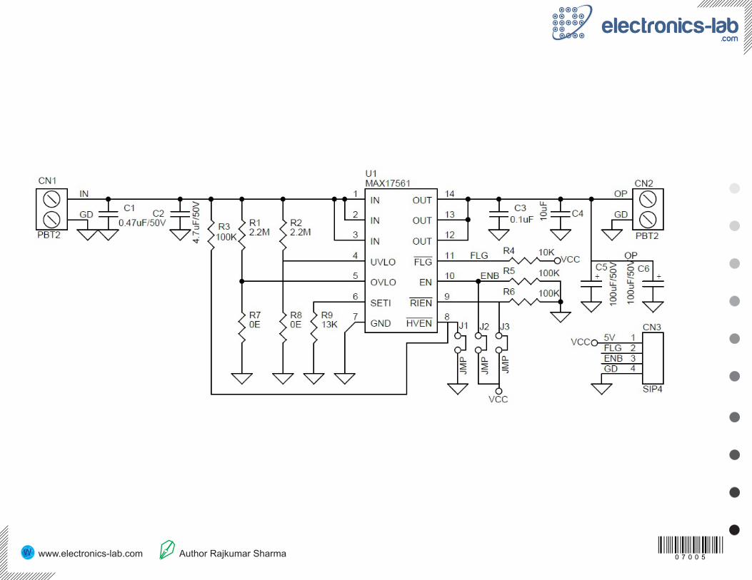
· Overvoltage-lockout (OVLO) thresholds are set using external resisters R1 and R7
· Undervoltage-lockout (UVLO) thresholds are set using external resistors R2 and R8
· Programmable Forward-Current Limit: 0.7A to 4.2A (±15% Accuracy) is set using R9 (R9 13K = Approx. 1Amp)
· Reverse Current Flow Control Input
· Thermal Overload Protection
· Dual Enable Inputs: EN and High Voltage HVEN
· Fault Indicator Output. FLAG goes low when the fault duration exceeds the blanking time, reverse current is detected, thermal-shutdown mode is active, OVLO threshold is reached, or SET-Current is connected to GND.
· Reverse-Current Enable Input. Open the Jumper J3 enable the reverse-current flow protection. Close the Jumper J3 (RIEN to logic-high) to disable the reverse-current flow protection
· EN: Close the Jumper J2 to enable the input (Active-High Enable Input)
· HVEN: Close the Jumper J1 to activate HVEN High voltage Enable (36V Capable Active-Low Enable Input)
0 7 0 0 5 www.electronics-lab.com Author Rajkumar Sharma www.twovolt.com
Switch ControlThere are two independent enable inputs (HVEN and EN) for the devices. HVEN is a high-voltage-capable input. Toggle HVEN or EN to reset the fault condition once a short circuit is detected and the devices shut down.
Jumper J1 Close, Jumper J2 Open >> Switch Status ONJumper J1 Close, Jumper J2 Close>> Switch Status ONJumper J1 Open, Jumper J2 Close>> Switch Status ONJumper J1 Open, Jumper J2 Open>> Switch Status OFFJumper J3: Open enable the reverse-current flow protection. Close the Jumper J3 (RIEN to logic-high) to disable the reverse-current flow protectionRefer the figure which explain the formula to set the over voltage, Under voltage, and Load Current.
Testing the boardPerform the following steps to test the project, Close Jumper 1 and Jumper 2, connect the voltmeter on output, Connect 5V DC power supply to VCC and GND pin of CN3. Use another variable power supply, adjust the voltage to 19.5V and connect this power supply to input CN1, verify that output is 19.5V DC and Flag pin is high. Gradually increase the DC power supply voltage and verify that OUT voltage goes down and Flag pin is low when input reached approximately 33V. Gradually decrease voltage on the DC power supply and verify that OUT comes back and Flag pin is high again when the input reaches approximately 32V. So the safe range of voltage input is 19.5V to 32V with Load Capacity 1 A. This project can work with a single power supply if Fault/Flag information is not required.
Default internal factory-pre-set internal OVLO threshold is 33V (typ.) and the pre-set internal UVLO threshold is 19.2V (typ.) The current-limit protection is set using R9 to 1A, but current limit protection is programable up to 4.2A, once current reaches the threshold, the MAX17561 turns off the output after the 20.7ms (typ) blanking time and stays off during the retry period.
Auto retry Current LimitWhen the current threshold is reached, the tBLANK timer begins counting. The FLAG asserts if the overcurrent condition is present for tBLANK. The timer resets if the overcurrent condition disappears before tBLANK has elapsed. A retry time delay, tRETRY, is started immediately after tBLANK has elapsed and during tRETRY time, the FETs are off. At the end of tRETRY, the FETs are turned on again. If the fault still exists, the cycle is repeated and the FLAG stays low. When the fault is removed, the FETs stay on. If the die temperature exceeds +150NC (typ) due to self-heating, the MAX17561 enables thermal shutdown until the die temperature drops by approximately 30NC . The autoretry feature reduces the system power in case of overcurrent or short-circuit conditions. During tBLANK time, when the switch is on, the supply current is held at the current current limit. During tRETRY time, when the switch is off, there is no current through the switch. Thus, the output current is much less than the programmed current limit. With a 20.7ms (typ) tBLANK and 600ms (typ) tRETRY, the duty cycle is 3.3%, resulting in a 96.7% power savings
Reverse-Current Block Enable (RIEN)This feature enables reverse-current protection and disables reverse-current flow from OUT to IN. The reverse-current block feature is useful in applications with inductive loads.
0 7 0 0 5 www.electronics-lab.com Author Rajkumar Sharma www.twovolt.com
0 7 0 0 5 www.electronics-lab.com Author Rajkumar Sharma www.twovolt.com
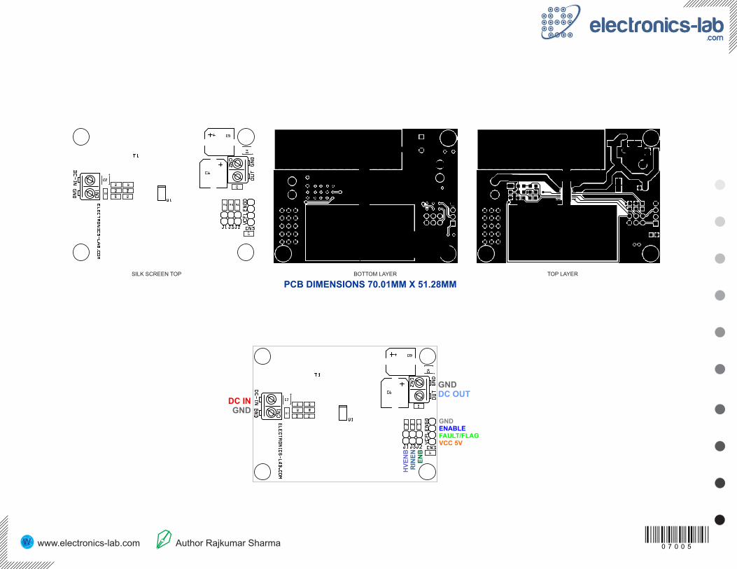
SILK SCREEN TOP BOTTOM LAYER TOP LAYER
PCB DIMENSIONS 70.01MM X 51.28MM
GNDENABLEFAULT/FLAGVCC 5V
DC INGND
GNDDC OUT
HV
EN
BR
INE
NE
NB
0 7 0 0 5 www.electronics-lab.com Author Rajkumar Sharma www.twovolt.com
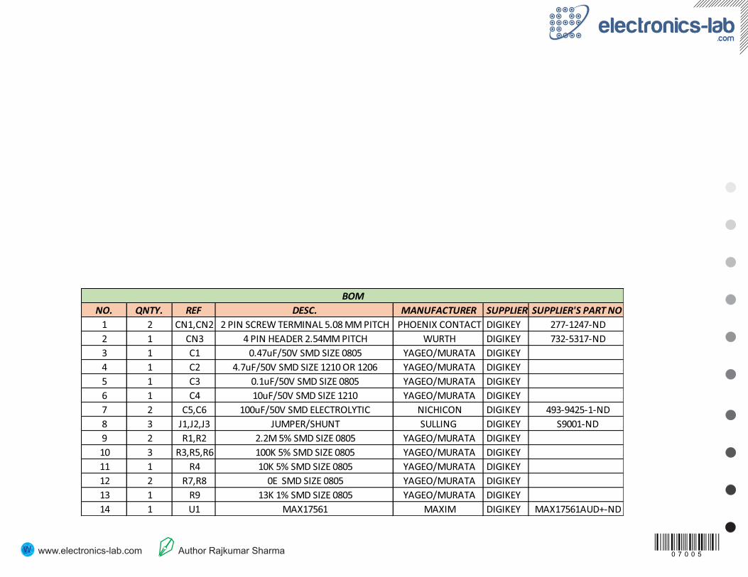
NO. QNTY. REF DESC. MANUFACTURER SUPPLIER SUPPLIER'S PART NO
1 2 CN1,CN2 2 PIN SCREW TERMINAL 5.08 MM PITCH PHOENIX CONTACT DIGIKEY 277-1247-ND
2 1 CN3 4 PIN HEADER 2.54MM PITCH WURTH DIGIKEY 732-5317-ND
3 1 C1 0.47uF/50V SMD SIZE 0805 YAGEO/MURATA DIGIKEY
4 1 C2 4.7uF/50V SMD SIZE 1210 OR 1206 YAGEO/MURATA DIGIKEY
5 1 C3 0.1uF/50V SMD SIZE 0805 YAGEO/MURATA DIGIKEY
6 1 C4 10uF/50V SMD SIZE 1210 YAGEO/MURATA DIGIKEY
7 2 C5,C6 100uF/50V SMD ELECTROLYTIC NICHICON DIGIKEY 493-9425-1-ND
8 3 J1,J2,J3 JUMPER/SHUNT SULLING DIGIKEY S9001-ND
9 2 R1,R2 2.2M 5% SMD SIZE 0805 YAGEO/MURATA DIGIKEY
10 3 R3,R5,R6 100K 5% SMD SIZE 0805 YAGEO/MURATA DIGIKEY
11 1 R4 10K 5% SMD SIZE 0805 YAGEO/MURATA DIGIKEY
12 2 R7,R8 0E SMD SIZE 0805 YAGEO/MURATA DIGIKEY
13 1 R9 13K 1% SMD SIZE 0805 YAGEO/MURATA DIGIKEY
14 1 U1 MAX17561 MAXIM DIGIKEY MAX17561AUD+-ND
BOM