Embed Size (px)
Citation preview
HIGH ACCURACY INDOOR LOCALIZATION: A WIFI-BASED APPROACH
Chen Chen?†, Yan Chen∗†, Hung-Quoc Lai†, Yi Han?†, and K.J. Ray Liu?†
? University of Maryland, College Park, MD 20742, USA† Origin Wireless, 223 Newbury Street Boston, MA 02116, USA
∗ School of Electronic Engineering, University of Electronic Science and Technology of China
ABSTRACT
Indoor positioning systems (IPS) based on Wi-Fi signals aregaining popularity recently. IPS based on Received SignalStrength Indicator (RSSI) could only achieve a precision ofseveral meters due to the strong temporal and spatial varia-tion of indoor environment. On the other hand, IPS based onChannel State Information (CSI) drive the precision into thesub-meter regime with several access points (AP). However,the performance degrades with fewer APs mainly due to thelimit of bandwidth. In this paper, we propose a Wi-Fi-basedtime-reversal indoor positioning system (WiFi-TRIPS) usingthe location-specific fingerprints generated by CSIs with a to-tal bandwidth of 1 GHz. WiFi-TRIPS consists of an offlinephase and an online phase. In the offline phase, CSIs arecollected in different 10 MHz bands from each location-of-interest and the timing and frequency synchronization errorsare compensated. We perform a bandwidth concatenation tocombine CSIs in different bands into a single fingerprint of 1GHz. In the online phase, we evaluate the time-reversal res-onating strength using the fingerprint from an unknown loca-tion and those in the database for location estimation. Exten-sive experiment results demonstrate a perfect 5cm precisionin an 20cm×70cm area in a non-line-of-sight office environ-ment with one link measurement.
Index Terms— WiFi, Localization, Channel State Infor-mation, Time-reversal Resonating Strength
1. INTRODUCTION
Wireless indoor positioning systems (IPS) have become pop-ular recently. It spawns a lot of location-based applications,such as personalized advertisement in a grocery store, touristguidance in a museum, and goods localization in a warehouse,to name a few.
Speaking of outdoor localization systems, Global Po-sitioning System (GPS) has provided routes to millions ofdrivers for years. However, the GPS signal could be too weakwhen it comes to indoor localization: the blocking of con-crete walls and floors severely attenuates the signal. On theother hand, the precision in the order of tens of meters is farfrom satisfactory for indoor applications.
Realizing these drawbacks, many researchers and com-panies harness the ubiquitous wireless local area networks(WLAN) powered by WiFi technology. Received SignalStrength Indicator (RSSI) is a MAC layer, coarse-grained in-formation available in mainstream wireless network interfacecontrollers (NIC) [1]. Thus, RSSI-based IPS have been wellstudied. In [2], the authors presented Horus which utilizedthe RSSIs reported by access points (AP) to build a radiomap in the offline phase. In the online phase, the RSSIs fromnearby APs are measured and matched to the radio map, re-sulting in a probabilistic location estimation. It achieved anaverage accuracy of 2m. Other RSSI-based systems such asRADAR [3] and MultiLoc [4] could achieve 3 ∼ 5m and2.7m in mean accuracy. However, RSSI-based schemes suf-fer in an environment with strong non-line-of-sight (NLOS)condition.
The precision could be further driven into sub-meterregime using channel state information (CSI), a physicallayer, fine-grained information at the receiver. Orthogonal-Frequency-Division-Multiplexing (OFDM) is one of thebaseband technique in WLANs, where CSIs are estimatedfrom the long training preambles (LTP) on subcarrier level infrequency domain. In [5], the authors proposed the PinLocsystem. They performed a wardriving to obtain CSIs fromAPs in an area of 1m× 1m in the offline phase. In the onlinephase, the similarity of the CSIs from multiple nearby APsand those in the offline phase was calculated for localiza-tion, resulting in 89% mean accuracy and 6% false positives.In [6], the authors proposed FIFS using the summation ofpower across subcarriers in CSI to achieve 0.60m medianaccuracy.
However, most IPS systems cannot achieve a centime-ter accuracy, particularly in an environment with scarce APsand/or strong NLOS condition. It is mainly due to the limitedbandwidth of 10 or 20 MHz in 802.11a/g/p WLANs, which isnot sufficient to resolve enough independent multipaths andconsequently, introduces ambiguity into the CSIs. In light ofthis, Wu et al. proposed Time-reversal (TR) indoor position-ing system (TRIPS) in [7] using a much larger bandwidth of125 MHz on the 5.4 GHz band. It utilized the super-resolutionspatial-temporal focusing effect of TR [8] in a rich-scatteringenvironment. It achieved a perfect 10cm localization accu-
6245978-1-4799-9988-0/16/$31.00 ©2016 IEEE ICASSP 2016
racy within a 0.9m× 1m area-of-interest in a NLOS environ-ment.
Inspired by TRIPS, we implement the WiFi-based TRIPS(WiFi-TRIPS). We extend from the 802.11a/g/p basebandprocessor developed in [9] on Universal Software Radio Pe-ripheral (USRP) [10] in the framework of GNU Radio [11].Instead of the pilot-assisted channel estimator in [9], we usethe two LTPs defined in 802.11a/g/p for channel estimation.To obtain CSIs from a much wider bandwidth, we perform afrequency sweeping of 1 GHz from 4.9 GHz to 5.9 GHz on asingle link.
Similar to TRIPS, WiFi-TRIPS consists of two phases. Inthe offline phase, WiFi-TRIPS collect CSIs from location-of-interest which are stored into the database. Three synchro-nization errors might exist in the CSIs: (i) Symbol TimingOffset (STO) caused by the misalignment between the cor-rect starting point of the frame and the estimated starting point(ii) Carrier Frequency Offset (CFO) caused by the differencebetween the two oscillators at the transmitter (TX) for up-conversion and the receiver (RX) for down-conversion (iii)Sampling Frequency Offset (SFO) caused by the differencein the sampling frequency between TX and RX. In order tocombat the residual timing and frequency synchronization er-ror, we propose an algorihm for compensation. With band-width concatenation, we combine the sanitized CSIs from dif-ferent bands into one fingerprint. In the online phase, the TRresonating strength is calculated for location estimation. Weperform extensive experiments with a unit distance of 5cmto demonstrate the centimeter-level accuracy of WiFi-TRIPSin a typical office environment during day time. We achievea perfect localization accuracy in an area of 20cm × 70cmusing only one link measurement of CSI.
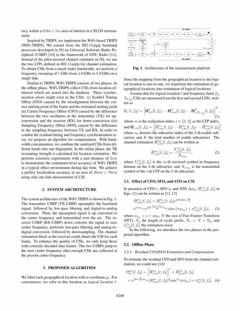
2. SYSTEM ARCHITECTURE
The system architecture of the WiFi-TRIPS is shown in Fig. 1.The transmitter USRP (TX-USRP) upsamples the basebandsignal, followed by low-pass filtering and digital-to-analogconversion. Then, the upsampled signal is up converted tothe center frequency and transmitted over the air. The re-ceiver USRP (RX-USRP) down converts the signal to zerocenter frequency, performs low-pass filtering and analog-to-digital conversion, followed by downsampling. The channelestimation block at the receiver could obtain the CSI for eachframe. To enhance the quality of CSIs, we only keep thosewith correctly decoded data frames. The two USRPs jump tothe next center frequency after enough CSIs are collected atthe present center frequency.
3. PROPOSED ALGORITHM
We label each geographical location with a coordinate p`. Forconvenience, we refer to this location as logical location `.
Const.
Mapping 64-Pt
IFFT
Add
CPLPF DAC
Up
Convert
Down
ConvertADCLPF
Remove
CP
64-Pt
FFT
Freq.
Sync
Timing
Sync
Channel
Est.
Decoding
Const.
Demap.
Equalizer
TX-USRP
RX-USRP
Fig. 1. Architecture of the measurement platform
Since the mapping from the geographical location to the logi-cal location is one-to-one, we transform the estimation of ge-ographical locations into estimation of logical locations.
Assume that for logical location ` and frequency band fd,N`,fd CSIs are measured from the first and second LTPs, writ-ten as
Hi [`, fd] =[HTi,1[`, fd] · · ·HT
i,m[`, fd] · · ·HTi,N`,fd
[`, fd]]T,
(1)where m is the realization index, i ∈ 1, 2 as the LTP index,and Hi,m[`, fd] =
[Hu1i,m[`, fd] · · · Huk
i,m[`, fd] · · · HuKi,m[`, fd]
]where uk denotes the subcarrier index of the k-th usable sub-carrier, and K the total number of usable subcarriers. Thechannel estimation Huk
i,m[`, fd] can be written as
Huki,m[`, fd] =
Y uki,m[`, fd]
Xi,uk
, (2)
where Y uki,m[`, fd] is the m-th received symbol in frequencydomain on the k-th subcarrier, and Xi,uk is the transmittedsymbol of the i-th LTP on the k-th subcarrier.
3.1. Effect of CFO, SFO, and STO on CSI
In presence of CFO ε, SFO η, and STO ∆n0, Huki,m[`, fd] in
Equ. (2) can be written as [12, 13]
Huki,m[`, fd] = Huk
i,m[`, fd]ej2π∆n0
ukN
ejπφuk ej2πiNs+Ng
N φuk sinc (πφuk) + nuki,m[`, fd], (3)
where φuk = ε + ηuk, N the size of Fast Fourier Transform(FFT), Ng the length of cyclic prefix, Ns = N + Ng , andnuki,m[`, fd] the estimation noise.
In the following, we introduce the two phases in the pro-posed algorithm.
3.2. Offline Phase
3.2.1. Residual CFO/SFO Estimation and Compensation
To estimate the residual CFO and SFO from the channel esti-mation, we could use [14]
Ωukm [`, fd] =[Huk
1,m[`, fd]]∗× Huk
2,m[`, fd]
= ej2πNsN φuk |Huk
1,m[`, fd]|2sinc2 (πφuk) + ψukm [`, fd], (4)
6246
where sinc2 (πφk) ≈ 1 since πφuk is small, and ψukm [`, fd] isthe cross terms. Therefore, φuk can be estimated by
φuk = ] [Ωukm [`, fd]] , (5)
where ][X] is the angle of X . Compensating φuk gives
Huki,m[`, fd] = Huk
i,m[`, fd]e−jπ ˆφuk e−j2π
Ng+(i−1)NsN
ˆφuk (6)
Substituting Equ. (6) into Equ. (1) and writing the updatedHi [`, fd] in Equ. (1) as Hi [`, fd], we take the average ofH1 [`, fd] and H2 [`, fd] as H [`, fd] = H1[`,fd]+H2[`,fd]
2 .
3.2.2. STO Estimation and Compensation
After removing the residual CFO and SFO, the STO still re-mains to be compensated. Write
H [`, fd] =[HT
1 [`, fd] · · · HTm[`, fd] · · · HT
N`,fd[`, fd]
]T,
(7)where Hm[`, fd] =
[Hu1m [`, fd] · · · Huk
m [`, fd] · · · HuKm [`, fd]
]is the CSI vector for the m-th realization on usable sub-carriers after CFO/SFO correction. Denote Aukm [`, fd] =
]Hukm [`, fd]
as the angle of Huk
m [`, fd], we take a phase
unwrapping on all Aukm [`, fd], which gives A′ukm [`, fd]. The
slope of A′ukm [`, fd] is linear with STO if we disregard the
noise and interference. To estimate the slope, we use a linearsquare fitting on A
′ukm [`, fd], leading to
∆n0 =N∑Kk=1 [(uk − u)]
[A′ukm [`, fd]−A
]2π∑Kk=1 [uk − u]
2, (8)
where u =∑Kk=1 ukK and A =
∑Kk=1 A
′ukm [`,fd]
K . Therefore,Hukm [`, fd] is corrected as
Hukm [`, fd] = Huk
m [`, fd]e−juk∆n0
2πN . (9)
3.2.3. Formulating the Localization Fingerprint
Write the CSI matrix after STO compensation as
H [`, fd] =[HT
1 [`, fd] · · · HTm[`, fd] · · · HT
N`,fd[`, fd]
]T,
(10)we could formulate a localization fingerprint at location ` andfrequency band fd as
S [`, fd] =1
N`,fd
N`,fd∑m=1
Hm[`, fd] ·Wm, (11)
where · stands for the dot product between two vectors. Wm
is a K-dimension vector given by
Wm =[wm[`, fd] wm[`, fd] · · · wm[`, fd]
], (12)
where wm[`, fd] = e−j][Hu1m [`,fd]].After bandwidth concatenation, the localization finger-
print G[`] can be written as
G[`] =[S [`, f1] S [`, f2] · · · S [`, fD]
], (13)
where D is the total number of frequency bands. The fin-gerprints for all locations ` = 1, 2, · · · , L are calculated andstored into the database.
3.3. Online Phase
3.3.1. Processing the CSIs
In this step, we repeat the procedures in the offline phase onthe CSIs collected from a location-of-interest to correct thesynchronization issues and combine the CSIs into the locationfingerprint.
3.3.2. Localization by Calculating Resonating Strength
For the location fingerprint G[`′] from a location-of-interest`′, the resonating strength is calculated as Equ. (14),
Φ[`, `′] =
∣∣∣∣ G[`]G[`′]†
||G[`]||2||G[`′]||2
∣∣∣∣2 , (14)
where † stands for transpose and conjugate, and ||X||2 the L2norm of vector X. When ` = `′, we have Φ[`, `′] = 1. Theestimated location ˆ′ is given as
ˆ′ =
arg max`∗ Φ[`∗, `′] , if max`∗ Φ[`∗, `′] ≥ Γ
0 ,max`∗ Φ[`∗, `′] < Γ(15)
where `∗ = 1, 2, · · · , L and Γ is the threshold. When ˆ′ = 0,we cannot achieve localization given G[`′]. It can be provedthat Equ. (14) is the frequency domain expression of the time-reversal resonating strength defined in [7]. In this sense, weare calculating the resonating strength virtually.
4. EXPERIMENT RESULTS
The experiments are performed in an office environment dur-ing day time. The two USRPs are placed on the wooden ar-chitecture as shown in Fig. 2, with a unit distance of 5cmhorizontally and vertically.
We use 30 dB gain at TX-USRP and 15 dB gain at theRX-USRP. RX-USRP locates on the wooden structure. Thetotal number of subcarriers is 64, with 52 usable subcarriersof index −26,−25, · · · ,−1, 1, · · · , 25, 26. The length ofcyclic prefix is 16 with FFT size 64. The distance betweenthe transmitter and receiver is 10 feet with a concrete wall inthe middle.
6247
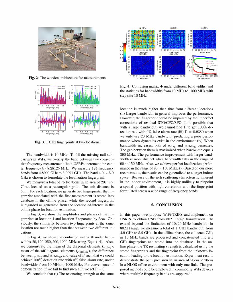
Fig. 2. The wooden architecture for measurements
5 5.2 5.4 5.6 5.80
0.5
1
1.5
2
2.5
Frequency (GHz)
Am
plit
ud
e
Loc 1, Test 1
Loc 1, Test 2
5 5.2 5.4 5.6 5.80
0.5
1
1.5
2
2.5
Frequency (GHz)
Am
plit
ud
e
Loc 1, Test 1
Loc 2, Test 1
5 5.2 5.4 5.6 5.8
−2
−1
0
1
2
3
Frequency (GHz)
Ph
ase
5 5.2 5.4 5.6 5.8
−2
0
2
Frequency (GHz)
Ph
ase
Fig. 3. 1 GHz fingerprints at two locations
The bandwidth is 10 MHz. To fill the missing null sub-carriers in WiFi, we overlap the band between two consecu-tive frequency measurement: both USRPs increment the cen-ter frequency by 8.28125 MHz. We measure 124 frequencybands from 4.8909 GHz to 5.9091 GHz. The band 4.9 ∼ 5.9GHz is chosen to formulate the localization fingerprint.
We measure a total of 75 locations in an area of 20cm ×70cm located on a rectangular grid. The unit distance is5cm. For each location, we generate two fingerprints: the fin-gerprint associated with the first measurement is stored intodatabase in the offline phase, while the second fingerprintis regarded as generated from the location-of-interest in theonline phase for location estimation.
In Fig. 3, we show the amplitudes and phases of the fin-gerprints at location 1 and location 2 separated by 5cm. Ob-viously, the similarity between two fingerprints at the samelocation are much higher than that between two different lo-cations.
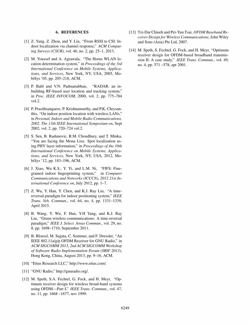
In Fig. 4, we show the confusion matrix Φ under band-widths 20, 120, 250, 500, 1000 MHz using Equ. (14). Also,we demonstrate the mean of the diagonal elements (µdiag),mean of the off-diagonal elements (µoffdiag), the differencebetween µdiag and µoffdiag, and value of Γ such that we couldachieve 100% detection rate with 0% false alarm rate, underbandwidths from 10 MHz to 1000 MHz. For convenience ofdemonstration, if we fail to find such a Γ, we set Γ = 0.
We conclude that (i) The resonating strength at the same
Fig. 4. Confusion matrix Φ under different bandwidths, andthe statistics for bandwidths from 10 MHz to 1000 MHz withstep size 10 MHz
location is much higher than that from different locations(ii) Larger bandwidth in general improves the performance.However, the fingerprint could be impaired by the imperfectcorrections of residual STO/CFO/SFO. It is possible thatwith a large bandwidth, we cannot find Γ to get 100% de-tection rate with 0% false alarm rate (iii) Γ = 0.9380 whenwe only use 20 MHz bandwidth, predicting a poor perfor-mance when dynamics exist in the environment (iv) Whenbandwidth increases, both of µdiag and µoffdiag decreases.The gap between them is maximized when bandwidth equals390 MHz. The performance improvement with larger band-width is more distinct when bandwidth falls in the range of90 ∼ 150 MHz. Also, we achieve perfect localization perfor-mance in the range of 90 ∼ 150 MHz. (v) Based on our morerecent results, the results can be generalized to a larger indoorspace. Because of the rich scattering characteristic inherentin the indoor environment, it is highly unlikely to pinpointa spatial position with high correlation with the fingerprintformulated across a wide range of frequency bands.
5. CONCLUSION
In this paper, we propose WiFi-TRIPS and implement onUSRPs to obtain CSIs from 802.11a/g/p transmission. Toextend beyond the limitation of 10/20 MHz bandwidth in802.11a/g/p, we measure a total of 1 GHz bandwidth, from4.9 GHz to 5.9 GHz. In the offline phase, the collected CSIsin 10 MHz bands are processed and concatenated into a 1GHz fingerprints and stored into the database. In the on-line phase, the TR resonating strength is calculated using thestored fingerprints and the fingerprint from the unknown lo-cation, leading to the location estimation. Experiment resultsdemonstrate the 5cm precision in an area of 20cm × 70cmin a NLOS office environment with only one-link. The pro-posed method could be employed in commodity WiFi deviceswhere multiple frequency bands are supported.
6248
6. REFERENCES
[1] Z. Yang, Z. Zhou, and Y. Liu, “From RSSI to CSI: In-door localization via channel response,” ACM Comput-ing Surveys (CSUR), vol. 46, no. 2, pp. 25–1, 2013.
[2] M. Youssef and A. Agrawala, “The Horus WLAN lo-cation determination system,” in Proceedings of the 3rdInternational Conference on Mobile Systems, Applica-tions, and Services, New York, NY, USA, 2005, Mo-biSys ’05, pp. 205–218, ACM.
[3] P. Bahl and V.N. Padmanabhan, “RADAR: an in-building RF-based user location and tracking system,”in Proc. IEEE INFOCOM, 2000, vol. 2, pp. 775–784vol.2.
[4] P. Prasithsangaree, P. Krishnamurthy, and P.K. Chrysan-this, “On indoor position location with wireless LANs,”in Personal, Indoor and Mobile Radio Communications,2002. The 13th IEEE International Symposium on, Sept2002, vol. 2, pp. 720–724 vol.2.
[5] S. Sen, B. Radunovic, R.M. Choudhury, and T. Minka,“You are facing the Mona Lisa: Spot localization us-ing PHY layer information,” in Proceedings of the 10thInternational Conference on Mobile Systems, Applica-tions, and Services, New York, NY, USA, 2012, Mo-biSys ’12, pp. 183–196, ACM.
[6] J. Xiao, Wu K.S., Y. Yi, and L.M. Ni, “FIFS: Fine-grained indoor fingerprinting system,” in ComputerCommunications and Networks (ICCCN), 2012 21st In-ternational Conference on, July 2012, pp. 1–7.
[7] Z. Wu, Y. Han, Y. Chen, and K.J. Ray Liu, “A time-reversal paradigm for indoor positioning system,” IEEETrans. Veh. Commun., vol. 64, no. 4, pp. 1331–1339,April 2015.
[8] B. Wang, Y. Wu, F. Han, Y.H Yang, and K.J. RayLiu, “Green wireless communications: A time-reversalparadigm,” IEEE J. Select. Areas Commun., vol. 29, no.8, pp. 1698–1710, September 2011.
[9] B. Bloessl, M. Segata, C. Sommer, and F. Dressler, “AnIEEE 802.11a/g/p OFDM Receiver for GNU Radio,” inACM SIGCOMM 2013, 2nd ACM SIGCOMM Workshopof Software Radio Implementation Forum (SRIF 2013),Hong Kong, China, August 2013, pp. 9–16, ACM.
[10] “Ettus Research LLC,” http://www.ettus.com/.
[11] “GNU Radio,” http://gnuradio.org/.
[12] M. Speth, S.A. Fechtel, G. Fock, and H. Meyr, “Op-timum receiver design for wireless broad-band systemsusing OFDM—Part I,” IEEE Trans. Commun., vol. 47,no. 11, pp. 1668 –1677, nov 1999.
[13] Tzi-Dar Chiueh and Pei-Yun Tsai, OFDM Baseband Re-ceiver Design for Wireless Communications, John Wileyand Sons (Asia) Pte Ltd, 2007.
[14] M. Speth, S. Fechtel, G. Fock, and H. Meyr, “Optimumreceiver design for OFDM-based broadband transmis-sion II: A case study,” IEEE Trans. Commun., vol. 49,no. 4, pp. 571 –578, apr 2001.
6249
![Avoiding Multipath to Revive Inbuilding WiFi Localizationksuweb.kennesaw.edu › ~she4 › 2015Summer › cs7860 › ...indoor localization techniques [1], yet it is hard to find](https://img.pdfslide.net/doc/110x75/60c8556f981a226ffa2dcb5b/avoiding-multipath-to-revive-inbuilding-wifi-a-she4-a-2015summer-a-cs7860.jpg)