Embed Size (px)
Citation preview

High adventure Model Regulatory g g yFramework for
Hydraulic Fracturing OperationsOperations
2011 National Environment, Energy and Resources Law
Summit
Banff, AlbertaApril 7-9, 2011
Mark K. BolingExecutive Vice President & General Counsel
The Promise of Natural Gas
• The Environment• The Environment• The Economyy• National Security
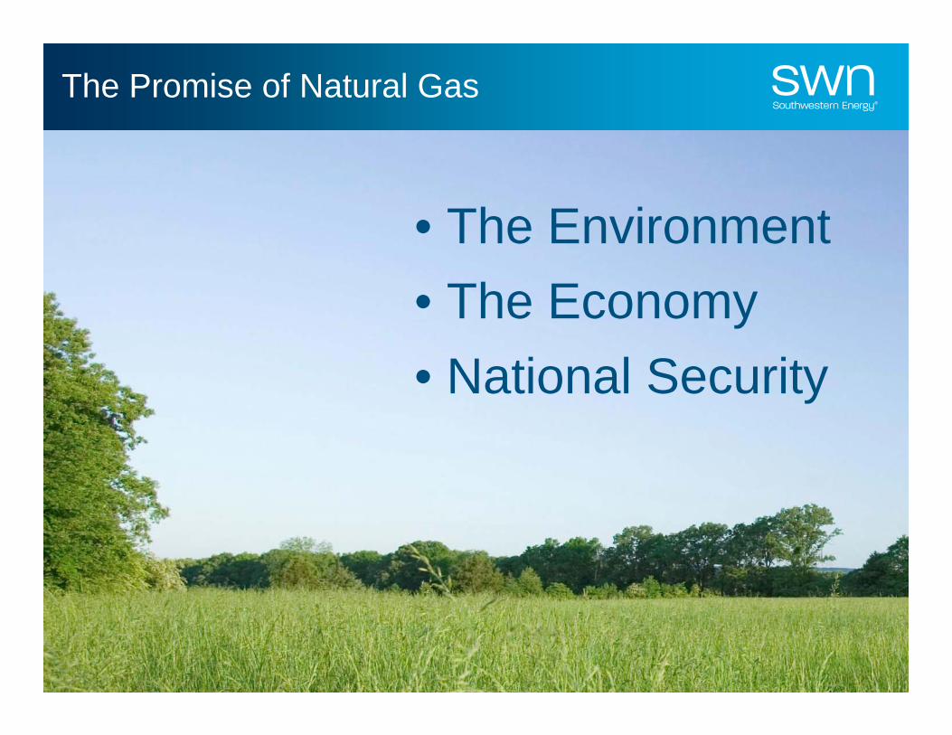
Current Regulatory Environment
• The EnvironmentPublic Distrust
and FearNatural Gas
Industry
• The Economy• The Environment
y• National SecurityTHE
PERFECTTHE
PERFECTPERFECTSTORM
PERFECTSTORM
CertainEnvironmental
Activists/Groups
ProposedFederal
Legislation

Refocusing the Debate
• Dial Down the Rhetoric
• Identify the Real Obstacles to Responsible Development of p pthis Resource
S• Develop Workable Solutions to Overcome these Obstacles
3

Regulatory Considerations
• Air Emissions
• Water Supply/Water Handling/Water Disposalg p
• Surface Impact– Drilling Locations (Pit
Construction; Chemical St E i C t l)
SurfaceConsiderations
Storage; Erosion Control)
– Infrastructure (Roads; Compressors; Pipelines; Water Treatment Facilities)
– Truck Traffic and Road Damage
• Protecting UndergroundSubsurface Protecting Underground Water Resources
• Frac Fluid Disclosure
SubsurfaceConsiderations
4
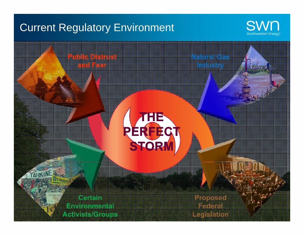
Protecting Underground Water Resources
MODELMODELREGULATORYFRAMEWORK
Well IntegrityIs the Key!
5
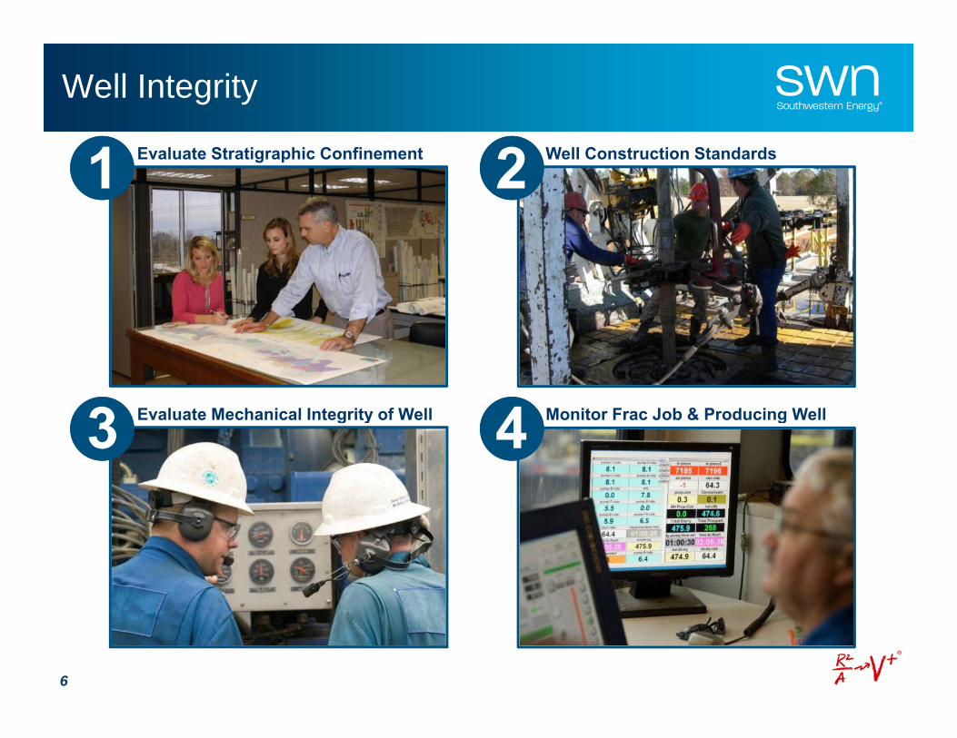
Well Integrity
Well Construction Standards2Evaluate Stratigraphic Confinement1
Evaluate Mechanical Integrity of Well3 Monitor Frac Job & Producing Well4Evaluate Mechanical Integrity of Well3 Monitor Frac Job & Producing Well4
6

Evaluating Stratigraphic Confinement1.
Virtually all fresh water wells are less than 500 feet deep in
the Fayetteville Shale area
Thousands of feet of rock separates the Fayetteville
Shale from shallow, freshwater zones
7
Cross sectional view

Evaluating Stratigraphic Confinement
• Differences in rock properties (i.e. strength and brittleness/elasticity) between the target formation (Fayetteville Shale) and surrounding formations (Morrow Shale & Hindsville Lime) act to contain hydraulic fractures within the target formation.
ee
• Hydraulic fractures follow the path of least resistance and continue to propagate ithi th F tt ill Sh l
8
within the Fayetteville Shale.

Microseismic Evaluation of Stimulation Treatment
Top Morrow ShaleCross
sectional viewLargest recorded seismic event generates the same amount of
energy as would be released when
Top Fayetteville Shale
dropping a gallon of milk from chest high to the floor.
Top Fayetteville Shale
Top Hindsville Limestone
~200’
8000
10000
100
120
0
Treating Pressure (psi)
Slurry Rate (bpm)
1000’
2000
4000
6000
psi
20
40
60
80
bbl/m
in o
r PPA
x10
Prop Conc (ppa x 10)
9
07:40:48 8:09:36 8:38:24 9:07:12 9:36:00 10:04:48 10:33:36
0

Evaluating Stratigraphic Confinement –Shallow Wells
Surface Casing 550’
400’ Usable Fresh Water
400’ Usable Fresh Water
Abandoned Well
2100’ Various AtokaSands & Shales
4 000’ of Sediment450’ Atoka
S d & Sh lTransmissive Fault
850’ In most shallow formations(less than 1 500’) the hydraulic
1300’ Upper Hale
4,000 of Sediment Sands & ShalesTransmissive Fault(less than 1,500 ), the hydraulic fracture will propagate in a
horizontal direction.
600’ Morrow Shale
300’ Fayetteville Shale
300’ Fayetteville Shale
Hindsville
10
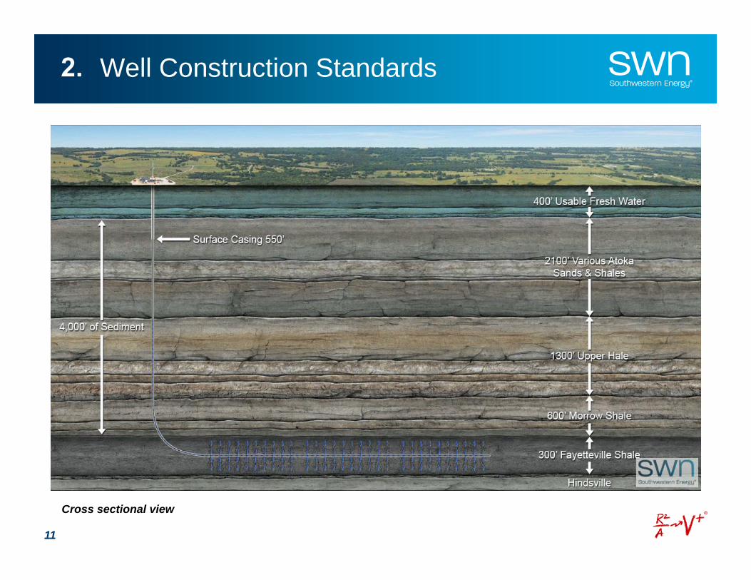
Well Construction Standards2.
11
Cross sectional view

WELL CONSTRUCTION STANDARDS
FRESH WATER AQUIFER ZONEFRESH WATER AQUIFER ZONECONDUCTOR PIPECONDUCTOR PIPE
SURFACE CASINGSURFACE CASING
CEMENTCEMENT
SURFACE CASINGSURFACE CASING
PRODUCTION CASINGPRODUCTION CASING
CEMENTCEMENT
SHALLOW PRODUCING ZONESHALLOW PRODUCING ZONE
CEMENTCEMENT
INTERMEDIATE PRODUCING ZONEINTERMEDIATE PRODUCING ZONE
Cross sectional view
TARGET PRODUCING ZONETARGET PRODUCING ZONE

Evaluating Mechanical Integrity of Well3.
• Internal Mechanical Integrity– Verify appropriateness of– Verify appropriateness of
proposed casing program (e.g., size, grade, minimum internal yield pressure, etc.)
– Test casing string to ensure it can withstand maximum stimulation pressure
• External Mechanical Integrity– Verify quality of cement– Identify top of cement– Test cement job (FIT, CBL, etc.) when operations indicate inadequate
coverage
13
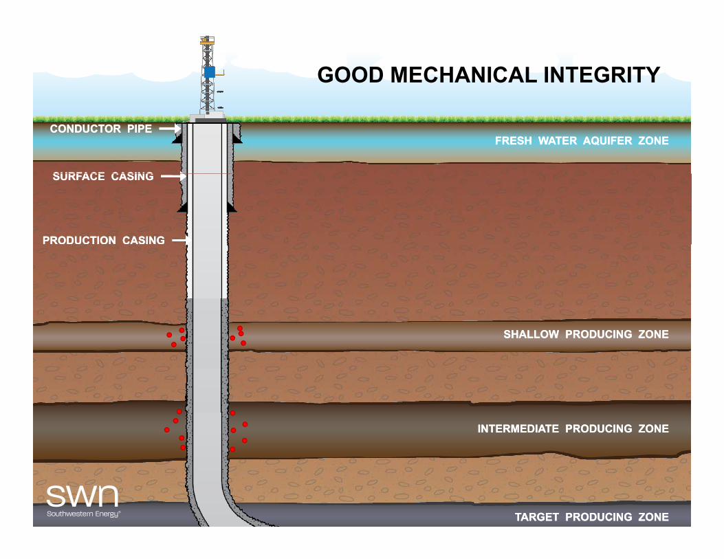
GOOD MECHANICAL INTEGRITY
FRESH WATER AQUIFER ZONEFRESH WATER AQUIFER ZONECONDUCTOR PIPECONDUCTOR PIPE
SURFACE CASINGSURFACE CASINGSURFACE CASINGSURFACE CASING
PRODUCTION CASINGPRODUCTION CASING
SHALLOW PRODUCING ZONESHALLOW PRODUCING ZONE
INTERMEDIATE PRODUCING ZONEINTERMEDIATE PRODUCING ZONE
TARGET PRODUCING ZONETARGET PRODUCING ZONE
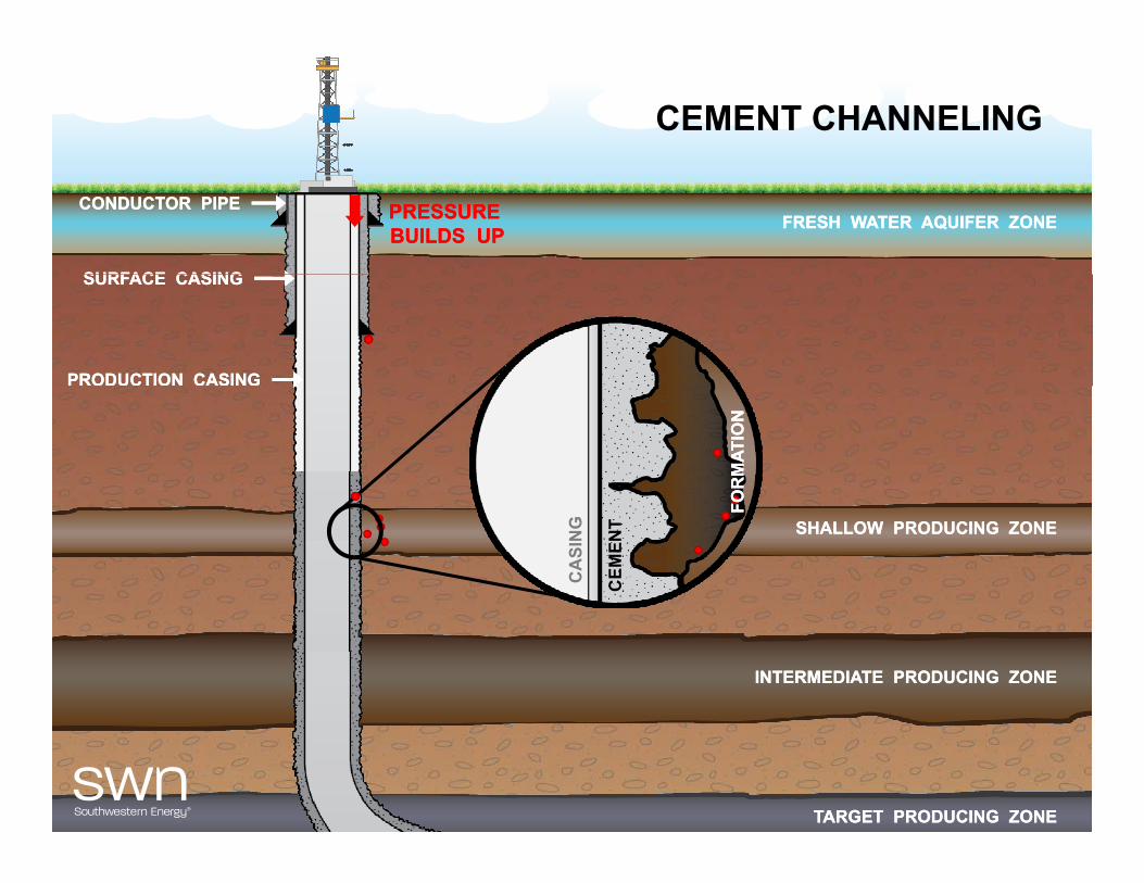
CEMENT CHANNELING
PRESSURE BUILDS UPPRESSURE BUILDS UP
CONDUCTOR PIPECONDUCTOR PIPE
SURFACE CASINGSURFACE CASING
FRESH WATER AQUIFER ZONEFRESH WATER AQUIFER ZONE
SURFACE CASINGSURFACE CASING
PRODUCTION CASINGPRODUCTION CASING
OR
MAT
ION
OR
MAT
ION
SHALLOW PRODUCING ZONESHALLOW PRODUCING ZONE
CA
SIN
G
CEM
ENT
FOFO
INTERMEDIATE PRODUCING ZONEINTERMEDIATE PRODUCING ZONE
TARGET PRODUCING ZONETARGET PRODUCING ZONE

LEAK THROUGH CASING
CONDUCTOR PIPECONDUCTOR PIPE
SURFACE CASINGSURFACE CASING
FRESH WATER AQUIFER ZONEFRESH WATER AQUIFER ZONEPRESSURE BUILDS UPPRESSURE BUILDS UP
SURFACE CASINGSURFACE CASING
PRODUCTION CASINGPRODUCTION CASING
FOR
MAT
ION
FOR
MAT
ION
NG
CA
SIN
SHALLOW PRODUCING ZONESHALLOW PRODUCING ZONE
INTERMEDIATE PRODUCING ZONEINTERMEDIATE PRODUCING ZONE
TARGET PRODUCING ZONETARGET PRODUCING ZONE

INSUFFICIENT CEMENT COVERAGE
PRESSURE BUILDS UPPRESSURE BUILDS UP
CONDUCTOR PIPECONDUCTOR PIPE
SURFACE CASINGSURFACE CASING
FRESH WATER AQUIFER ZONEFRESH WATER AQUIFER ZONE
SURFACE CASINGSURFACE CASING
PRODUCTION CASINGPRODUCTION CASING
SHALLOW PRODUCING ZONESHALLOW PRODUCING ZONE
INTERMEDIATE PRODUCING ZONEINTERMEDIATE PRODUCING ZONE
TARGET PRODUCING ZONETARGET PRODUCING ZONE
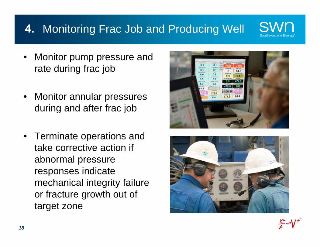
Monitoring Frac Job and Producing Well4.
• Monitor pump pressure and rate during frac job
• Monitor annular pressures during and after frac jobduring and after frac job
• Terminate operations andTerminate operations and take corrective action if abnormal pressure responses indicateresponses indicate mechanical integrity failure or fracture growth out of target zone
18