Embed Size (px)
Citation preview

FOR DISTRIBUTION USE ONLY - NOT TO BE USED AT POINT OF RETAIL SALE
5543990-XTG-E-0719
TECHNICAL GUIDE
High Ambient &
High Efficiency
ZM SERIES4 - 7.5 TON50 HERTZ

5543990-XTG-E-0719
2 Johnson Controls Ducted Systems
Table of contents
Table of contents . . . . . . . . . . . . . . . . . . . . . . . . . . . . . . . . . . . . . . . . . . . . . . . . . . . . . . . . . . . . . . . . . . . . . . . . . . . . . . . . . . . . . . . 2
Component location . . . . . . . . . . . . . . . . . . . . . . . . . . . . . . . . . . . . . . . . . . . . . . . . . . . . . . . . . . . . . . . . . . . . . . . . . . . . . . . . . . . . . 3
Factory installed options . . . . . . . . . . . . . . . . . . . . . . . . . . . . . . . . . . . . . . . . . . . . . . . . . . . . . . . . . . . . . . . . . . . . . . . . . . . . . . . . . 6
Field installed accessories . . . . . . . . . . . . . . . . . . . . . . . . . . . . . . . . . . . . . . . . . . . . . . . . . . . . . . . . . . . . . . . . . . . . . . . . . . . . . . . . 7
Nomenclature . . . . . . . . . . . . . . . . . . . . . . . . . . . . . . . . . . . . . . . . . . . . . . . . . . . . . . . . . . . . . . . . . . . . . . . . . . . . . . . . . . . . . . . . . . 8
ZM cooling rating table . . . . . . . . . . . . . . . . . . . . . . . . . . . . . . . . . . . . . . . . . . . . . . . . . . . . . . . . . . . . . . . . . . . . . . . . . . . . . . . . . . 10
Outdoor sound power levels . . . . . . . . . . . . . . . . . . . . . . . . . . . . . . . . . . . . . . . . . . . . . . . . . . . . . . . . . . . . . . . . . . . . . . . . . . . . . 10
Physical data . . . . . . . . . . . . . . . . . . . . . . . . . . . . . . . . . . . . . . . . . . . . . . . . . . . . . . . . . . . . . . . . . . . . . . . . . . . . . . . . . . . . . . . . . . 11
Capacity performance . . . . . . . . . . . . . . . . . . . . . . . . . . . . . . . . . . . . . . . . . . . . . . . . . . . . . . . . . . . . . . . . . . . . . . . . . . . . . . . . . . 20
Airflow performance . . . . . . . . . . . . . . . . . . . . . . . . . . . . . . . . . . . . . . . . . . . . . . . . . . . . . . . . . . . . . . . . . . . . . . . . . . . . . . . . . . . . 33
Electrical data . . . . . . . . . . . . . . . . . . . . . . . . . . . . . . . . . . . . . . . . . . . . . . . . . . . . . . . . . . . . . . . . . . . . . . . . . . . . . . . . . . . . . . . . . 41
Typical wiring diagrams . . . . . . . . . . . . . . . . . . . . . . . . . . . . . . . . . . . . . . . . . . . . . . . . . . . . . . . . . . . . . . . . . . . . . . . . . . . . . . . . . 42
Weights and dimensions . . . . . . . . . . . . . . . . . . . . . . . . . . . . . . . . . . . . . . . . . . . . . . . . . . . . . . . . . . . . . . . . . . . . . . . . . . . . . . . . 47
Guide specifications . . . . . . . . . . . . . . . . . . . . . . . . . . . . . . . . . . . . . . . . . . . . . . . . . . . . . . . . . . . . . . . . . . . . . . . . . . . . . . . . . . . . 54
Product highlights• Assembled in Norman, Oklahoma (Made in U.S.A.)
• R-410A refrigerant
• Cooling only
• Scroll compressors
• State of the art microprocessor controls with specific programming for product applications
• Evaporator and condenser coils utilize copper tube with aluminum fin design for proven reliability and performance.
Options and accessories• Smoke detectors
• Hinged cabinet doors

5543990-XTG-E-0719
Johnson Controls Ducted Systems 3
Component location
Cooling only (4 ton)
Click on the letters to see a description of the features.
B
D
E
F
G
H
A
B
C
E
F
G

5543990-XTG-E-0719
4 Johnson Controls Ducted Systems
Features and benefits
A All models utilize a scroll compressor that are environmentally friendly by utilizing R-410A refrigerant. Use of the scroll compressor technology means a simple internal design, fewer moving parts, equating to a quiet, reliable, easy to service and efficient system. Internal compressor protection is standard and compressors include protection to prevent liquid damage.
Total system design - A TXV is used for precise metering on the 4-5 ton products. A single circuit, single compressor design is used on the 4-5 ton units for cost effectiveness and reliability without compromising quality.
System protection - Liquid line filter-driers, high and low pressure safeties are standard on each independent refrigerant circuit. Suction line sensors monitor temperature to prevent possible liquid flood back to the compressors and also protect against loss of charge and coil frosting.
B Balanced outdoor fan design makes for a quieter unit -The outdoor condenser fans are dynamically balanced for
better performance and reliability. The direct drive fan design mounted to the fan grill allows for quick and easy service. Where other's components might fail at extreme temperatures Our units are tested and rated up to 125°F (52°C) ambient cooling operation.
C Convertible filter rack - No tools required for easy field conversion of the filter rack to accommodate either 2-in. (51 mm) or 4-in. (102 mm) filters. Units ship with MERV 4 throwaway filters standard; however MERV 8 and MERV 13 filters can be easily added through the tool-free filter access panel to meet LEED requirements. Refer to physical data tables for filter size details.
D Units come with the new state of the art Smart Equipment™ control system. The new unit control incorporates the best of the already proven Smart Equipment™ controls and creates a more robust, intelligent control. The goal of this control is to utilize cutting edge technology making the equipment easier to install, operate, and service. All units are Factory commissioned, configured, and run tested.

5543990-XTG-E-0719
Johnson Controls Ducted Systems 5
Phase monitor - All ZM products come with a factory-installed phase monitor that is designed to prevent unit damage. The phase monitor shuts down the unit in an out-of phase condition.
Versatile - The Smart Equipment™ control can be configured to use with a standard thermostat (easy to connect screw terminals), a zone sensor, or can be setup to communicate with multiple BAS communication protocols to integrate with building automation systems.
Reduce field installed complexity - Each unit comes equipped with factory installed supply air, return air, and outdoor air temperature sensors providing key temperature readings thus reduce field installed complexity.
On-board USB port - The new control comes with a long list of features including data logging, current and previous system faults and software update capabilities using the on board USB port and common flash drive. Energy use monitoring capabilities allow custom tailoring to allow a system to work more efficiently at all times and occupancy levels. Self test and start-up reports also available from the board VIA the USB port.
Embedded LCD display - The board has a easy to read, built-in LCD display and easy to use navigation joystick and buttons allowing the user to quickly navigate the menus displaying unit status, options, current function, supply, return and outdoor temperatures, fault codes and other information.
Safety monitoring - The control monitors the outdoor, supply, and return air temperatures and the high and low pressure switch status on the independent refrigerant circuits. On units with heating the gas valve and high temperature limit switches are monitored on gas and electric heating units. The control also monitors the voltage supplied to the unit and will protect the unit if low voltage due to a brown out, or other electrical issue occurs.
Low ambient - An integrated low-ambient control allows units to operate in the cooling mode down to 0°F (-18°C) outdoor ambient without additional components or intervention. Optionally, the control board can be programmed to lockout the compressors when the outdoor air temperature is low or when free cooling is available.
Anti-short cycle protection - To aid compressor life, an anti- short cycle delay is incorporated into the standard control. Compressor reliability is further ensured by programmable minimum run times. For testing, the anti-short cycle delay can be temporarily overridden with the push of a button.
Fan delays - Fan on and fan off delays are fully programmable. Furthermore, the heating and cooling fan delay times are independent of one another. All units are programmed with default values based upon their configuration of cooling and/or heating capacity.
Nuisance trip protection and three strikes - To prevent nuisance calls, the control board uses a three times, you're out philosophy. The high, low-pressure switch, anti-freeze protection, low voltage or heating high limit must trip three times within two hours before the unit control board will lock out the
associated compressor. The same safety must trip three times before a hard lockout will occur.
E Robust design - Each unit is designed with an embossed top to increase structural support and ensure rigidity. The unit has a powder paint exterior finish including a industry leading 750-hour salt spray rating. All units are painted with a long lasting, powder paint that stands up over the life of the unit.
F Full perimeter base rail that fits on many existing curbs - This product was designed with the replacement market in mind which is why it fits on many existing curbs in the field but it also takes into account the new construction market by being versatile and sturdy. This unit is equipped with heavier gauge and innovatively designed base rails to prevent damage from transporting and rigging.

5543990-XTG-E-0719
6 Johnson Controls Ducted Systems
G Coils - All evaporator coils utilize copper tube with aluminum fin design for proven reliability and performance.
H Rigid mounted blower assembly - Dynamically balanced indoor fans ensure better performance and reliability. Large access panels for easier access, service, and maintenance. X13 belt drive (standard static option) available on 4-5 ton products. The X13 motor technology offers several benefits w/ respect to efficiency, operation, comfort, and cost when compared to other motors.
Factory installed options
(Nomenclature digit position)
Coil options (10)
E-Coat coils – Coils are coated with an epoxy polymer coating to protect against corrosion.
• A = Standard Indoor & Outdoor Coils (fin/tube design on indoor coil and on outdoor coil with no E-Coat coating added).
• B = Standard Indoor Coil & E-Coat Coil Outdoor Coil (fin/tube design on indoor coil and on outdoor coil. E-Coat coating added to outdoor coil)
• C = E-Coat Indoor Coil & Standard Outdoor Coil (fin/tube design on indoor coil and on outdoor coil. E-Coat coating added to indoor coil)
• D = E-Coat Indoor Coil & Outdoor Coil (fin/tube design on indoor coil and on outdoor coil. E-Coat coating added to indoor and outdoor coil)
Controls (11)
Smart Equipment™ - This is the Standard microprocessor control with capabilities to work with a sensor or thermostat only. Smart Equipment™ with BAS includes communication board with BACnet open-protocol system.
Verasys - Verasys provides a simple user experience with configurable self-recognizing controllers without the need for any additional tools. Verasys creates enhanced integration of HVACR equipment, zoning, and controls. Contractors are able to offer a complete bundled solution of equipment and controls to serve the light commercial market.
• A = Smart Equipment™
• B = Smart Equipment™ + BACnet MSTP, Mdbs, N2 COM Card
• C = Fault Detection Diagnostics (FDD) Refrigerant Side1
• J = Verasys Single Zone
• K = Verasys Change Over Bypass
• M = Verasys Single Zone W/FDD
• N = Verasys Change Over Bypass W/FDD
1. A factory installed control system option on the commercial equipment that constantly monitors refrigerant circuit pressures, refrigerant circuit temperatures, as well as the environmental temperatures and humidity via multiple sensor inputs.
Sensor options (12)
• 1 = None (units come standard with factory installed supply air, return air, and outdoor air temperature sensors)
• 2 = RA1 smoke detector
• 3 = SA smoke detector
• 4 = RA1 and SA smoke detector
1. Return Air Smoke Detector Sensor Must Be Relocated in the Field. (See Unit Installation Manual.)
Cabinet Options (16)
Hinged Cabinet Doors - The factory installed hinged panel option saves time, money and labor while allowing easy servicing of blower components, filters and controls. With this option there is no longer a need to remove panels to access these critical sections and running the risk of losing panels or roof damage from loose panels and materials. Extra care was taken to design a durable hinged panel with leak tight seal.
• None
• Hinged cabinet doors

5543990-XTG-E-0719
Johnson Controls Ducted Systems 7
Field installed accessories
• Roof curbs - The roof curbs have insulated decks and are shipped disassembled The roof curbs are available in 14-in. (356 mm) and 24-in. (610 mm) heights.
• Thermostat - The units are designed to operate with 24- volt electronic and electro-mechanical thermostats. All 7.5 through 12.5 ton units operate with two-stage heat/two-stage cool or two-stage cooling only thermostats, depending upon unit configuration.
• Smoke detectors - The smoke detectors stop operation of the unit by interrupting power and providing a fault message to the control board if smoke is detected within
the air compartment. Smoke detectors are available for both the supply and/or return air configurations.
• Hinged filter access panel - Allows hinged access to the filter section.
• Low ambient head pressure control kit - The Electronic Low Ambient Controller is designed to regulate condenser head pressure at low ambient temperatures by varying the amount of airflow through the condenser.
• Through the base connection - Kits are available to provide a way to route wiring to the unit through the base of the unit and gas supplied to the unit through the base or through the curb. These kits provide a seal tight way to bring power and gas to the unit without additional roof penetrations.

5543990-XTG-E-0719
8 Johnson Controls Ducted Systems
Nomenclature
ZM E 05 A 7 A 1 A 1 5 1 U 2
Product Category
ZM = Pkg AC R410A Middle East(High Ambient and High Efficiency)
A = Standard Drive
Airflow
Product Generation
2 = Second Generation
Heat Type
E = No Heat, Cooling only
Nominal Cooling Capacity
04 = 3 Ton / 10 kW 05 = 4 Ton / 14 kW06 = 5 Ton / 18 kW07 = 6 Ton / 21 kW08 = 7.5 Ton / 26 kW
See catalog for ratings at 95ºF, 118.4ºF, 125.6ºF
Voltage
Special Options - Country
U = Kuwait
Q = QatarE = Emirates, others
1 = None 3 = Hinged Cabinet Doors
Cabinet Options
1 = None
1 = None
Economizer / Damper
A = None
2 = Return Air Smoke Detector 1, 2
3 = Supply Air Smoke Detector 2
4 = Return Air 1 and Supply Air Smoke Detector 2
Electrical Options
Options
A = Standard Indoor and Outdoor CoilsB = Standard Indoor Coil and ElectroFin Outdoor CoilC = E-Coat Indoor Coil and Standard Outdoor CoilD = E-Coat Indoor and Outdoor Coils
Heat Size
A = No Heat (Cooling Only)
Coil Options
7 = 380/415V-3-50Hz
Convenience Outlet
Sensor Options
Controls
1AA
5 = Phase Monitor (standard)
A = Smart Equipment™
1 = None (units come standard with factory-installed supply air, return air, and outdoor air temperature sensors)
1. The return air smoke detector sensor must be relocated in the field. Refer to the unit installation manual.2. Available as field-installed options.
Nomenclature for 3 to 7.5 Ton / 10 kW to 26 kW Model Numbers

5543990-XTG-E-0719
Johnson Controls Ducted Systems 9
Accessories
Accessory kit number
Description Where used Voltage
1RC0456 Curb Rigid 14-in. (356 mm) Small Footprint ZM05 All
1RC0457 Curb Rigid 14-in. (356 mm) Large Footprint ZM06, ZM07, ZM08 All
1RC0458 Curb Rigid 24-in. (610 mm) Small Footprint ZM05 All
1RC0459 Curb Rigid 24-in. (610 mm) Large Footprint ZM06, ZM07, ZM08 All
2SD04701224 Supply Air Stream Smoke Detector ZM05, ZM06, ZM07, ZM08 All
2SD04701124 Return Air Stream Smoke Detector ZM05 All
2SD04701424 Return Air Stream Smoke Detector ZM06, ZM07, ZM08 All
2SD04701324 Combination Supply & Return Air Stream Smoke Detector ZM05 All
2SD04701624 Combination Supply & Return Air Stream Smoke Detector ZM06, ZM07, ZM08 All

5543990-XTG-E-0719
10 Johnson Controls Ducted Systems
ZM cooling rating table
The following data is tested at an ambient condition of 118°F (48°C).
Outdoor sound power levels
UnitCooling stages
Nominal cooling capacity
(tons)
Gross cooling capacity (kWh)
Gross cooling capacity (MBH)
Total power (kW)
SEEREER
(cooling only)
EER (A/C with gas heat)
IEER (cooling
only)
IEER (A/C with gas heat)
IEER with IntelliSpeed
(cooling only)
IEER with IntelliSpeed (gas heat)
ZM05 1 4 12.89 43.97 5.14 --- 8.54 --- --- --- --- ---
ZM06 1 5 16.56 56.49 6.5 --- 8.63 --- --- --- --- ---
ZM07 1 6 20.43 69.70 8.01 --- 8.62 --- --- --- --- ---
ZM08 1 7.5 25.28 86.27 10.05 --- 8.58 --- --- --- --- ---
Unit (tons)Sound rating1
(dB-A)
1. Rated in accordance with AHRI 270 standard.
Octave bands (Hz)
63 125 250 500 1000 2000 4000 8000
ZM05 (4) 75 70 80 74 71 71 65 62 60
ZM06 (5) 85 86 87 83 82 79 75 74 69
ZM07 (6) 81 94 87 80 77 76 70 67 63
ZM08 (7.5) 80 91 85 81 78 75 69 67 64
5543990-XTG-E-0719
Johnson Controls Ducted Systems 11
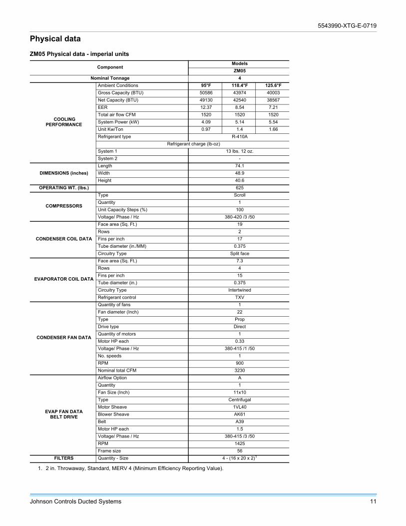
Physical data
ZM05 Physical data - imperial units
ComponentModels
ZM05
Nominal Tonnage 4
COOLINGPERFORMANCE
Ambient Conditions 95°F 118.4°F 125.6°F
Gross Capacity (BTU) 50586 43974 40003
Net Capacity (BTU) 49130 42540 38567
EER 12.37 8.54 7.21
Total air flow CFM 1520 1520 1520
System Power (kW) 4.09 5.14 5.54
Unit Kw/Ton 0.97 1.4 1.66
Refrigerant type R-410A
Refrigerant charge (lb-oz)
System 1 13 lbs. 12 oz.
System 2 -
DIMENSIONS (inches)
Length 74.1
Width 48.9
Height 40.6
OPERATING WT. (lbs.) 625
COMPRESSORS
Type Scroll
Quantity 1
Unit Capacity Steps (%) 100
Voltage/ Phase / Hz 380-420 /3 /50
CONDENSER COIL DATA
Face area (Sq. Ft.) 19
Rows 2
Fins per inch 17
Tube diameter (in./MM) 0.375
Circuitry Type Split face
EVAPORATOR COIL DATA
Face area (Sq. Ft.) 7.3
Rows 4
Fins per inch 15
Tube diameter (in.) 0.375
Circuitry Type Intertwined
Refrigerant control TXV
CONDENSER FAN DATA
Quantity of fans 1
Fan diameter (Inch) 22
Type Prop
Drive type Direct
Quantity of motors 1
Motor HP each 0.33
Voltage/ Phase / Hz 380-415 /1 /50
No. speeds 1
RPM 900
Nominal total CFM 3230
EVAP FAN DATABELT DRIVE
Airflow Option A
Quantity 1
Fan Size (Inch) 11x10
Type Centrifugal
Motor Sheave 1VL40
Blower Sheave AK61
Belt A39
Motor HP each 1.5
Voltage/ Phase / Hz 380-415 /3 /50
RPM 1425
Frame size 56
FILTERS Quantity - Size 4 - (16 x 20 x 2)1
1. 2 in. Throwaway, Standard, MERV 4 (Minimum Efficiency Reporting Value).
5543990-XTG-E-0719
12 Johnson Controls Ducted Systems
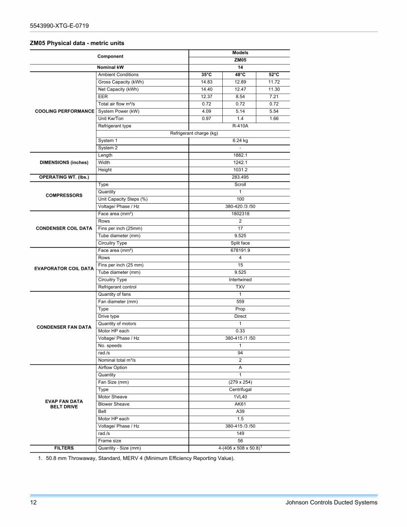
ZM05 Physical data - metric units
ComponentModels
ZM05
Nominal kW 14
COOLING PERFORMANCE
Ambient Conditions 35°C 48°C 52°C
Gross Capacity (kWh) 14.83 12.89 11.72
Net Capacity (kWh) 14.40 12.47 11.30
EER 12.37 8.54 7.21
Total air flow m³/s 0.72 0.72 0.72
System Power (kW) 4.09 5.14 5.54
Unit Kw/Ton 0.97 1.4 1.66
Refrigerant type R-410A
Refrigerant charge (kg)
System 1 6.24 kg
System 2 -
DIMENSIONS (inches)
Length 1882.1
Width 1242.1
Height 1031.2
OPERATING WT. (lbs.) 283.495
COMPRESSORS
Type Scroll
Quantity 1
Unit Capacity Steps (%) 100
Voltage/ Phase / Hz 380-420 /3 /50
CONDENSER COIL DATA
Face area (mm²) 1802318
Rows 2
Fins per inch (25mm) 17
Tube diameter (mm) 9.525
Circuitry Type Split face
EVAPORATOR COIL DATA
Face area (mm²) 678191.9
Rows 4
Fins per inch (25 mm) 15
Tube diameter (mm) 9.525
Circuitry Type Intertwined
Refrigerant control TXV
CONDENSER FAN DATA
Quantity of fans 1
Fan diameter (mm) 559
Type Prop
Drive type Direct
Quantity of motors 1
Motor HP each 0.33
Voltage/ Phase / Hz 380-415 /1 /50
No. speeds 1
rad./s 94
Nominal total m³/s 2
EVAP FAN DATABELT DRIVE
Airflow Option A
Quantity 1
Fan Size (mm) (279 x 254)
Type Centrifugal
Motor Sheave 1VL40
Blower Sheave AK61
Belt A39
Motor HP each 1.5
Voltage/ Phase / Hz 380-415 /3 /50
rad./s 149
Frame size 56
FILTERS Quantity - Size (mm) 4-(406 x 508 x 50.8)1
1. 50.8 mm Throwaway, Standard, MERV 4 (Minimum Efficiency Reporting Value).
5543990-XTG-E-0719
Johnson Controls Ducted Systems 13
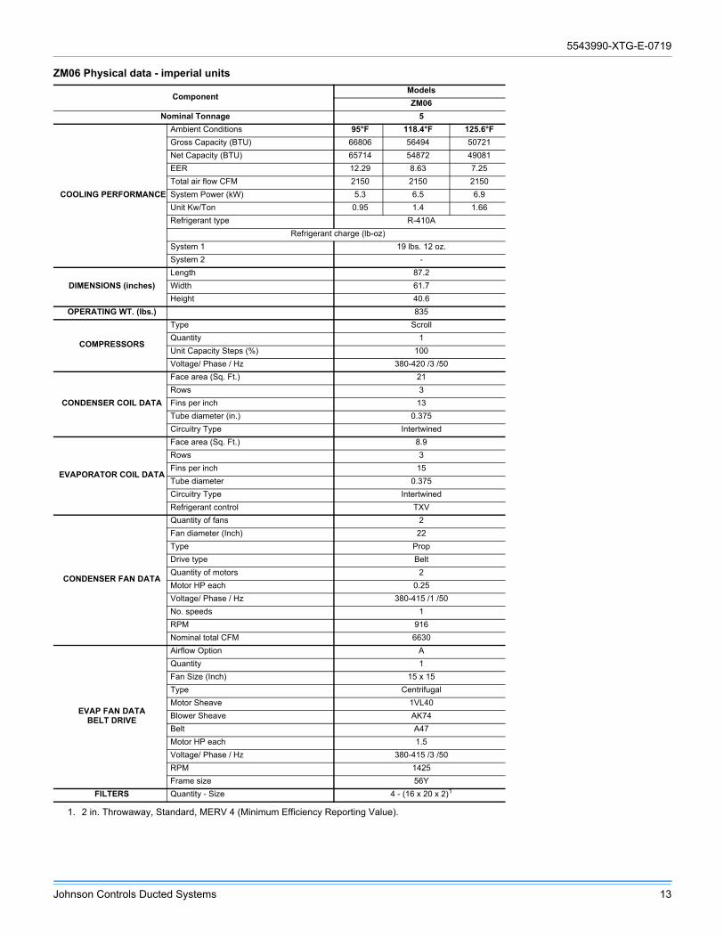
ZM06 Physical data - imperial units
ComponentModels
ZM06
Nominal Tonnage 5
COOLING PERFORMANCE
Ambient Conditions 95°F 118.4°F 125.6°F
Gross Capacity (BTU) 66806 56494 50721
Net Capacity (BTU) 65714 54872 49081
EER 12.29 8.63 7.25
Total air flow CFM 2150 2150 2150
System Power (kW) 5.3 6.5 6.9
Unit Kw/Ton 0.95 1.4 1.66
Refrigerant type R-410A
Refrigerant charge (lb-oz)
System 1 19 lbs. 12 oz.
System 2 -
DIMENSIONS (inches)
Length 87.2
Width 61.7
Height 40.6
OPERATING WT. (lbs.) 835
COMPRESSORS
Type Scroll
Quantity 1
Unit Capacity Steps (%) 100
Voltage/ Phase / Hz 380-420 /3 /50
CONDENSER COIL DATA
Face area (Sq. Ft.) 21
Rows 3
Fins per inch 13
Tube diameter (in.) 0.375
Circuitry Type Intertwined
EVAPORATOR COIL DATA
Face area (Sq. Ft.) 8.9
Rows 3
Fins per inch 15
Tube diameter 0.375
Circuitry Type Intertwined
Refrigerant control TXV
CONDENSER FAN DATA
Quantity of fans 2
Fan diameter (Inch) 22
Type Prop
Drive type Belt
Quantity of motors 2
Motor HP each 0.25
Voltage/ Phase / Hz 380-415 /1 /50
No. speeds 1
RPM 916
Nominal total CFM 6630
EVAP FAN DATABELT DRIVE
Airflow Option A
Quantity 1
Fan Size (Inch) 15 x 15
Type Centrifugal
Motor Sheave 1VL40
Blower Sheave AK74
Belt A47
Motor HP each 1.5
Voltage/ Phase / Hz 380-415 /3 /50
RPM 1425
Frame size 56Y
FILTERS Quantity - Size 4 - (16 x 20 x 2)1
1. 2 in. Throwaway, Standard, MERV 4 (Minimum Efficiency Reporting Value).

5543990-XTG-E-0719
14 Johnson Controls Ducted Systems
ZM06 Physical data - metric units
ComponentModels
ZM06
Nominal kW 18
COOLING PERFORMANCE
Ambient Conditions 35°C 48°C 52°C
Gross Capacity (kWh) 19.58 16.56 14.86
Net Capacity (kWh) 14.86 16.08 14.38
EER 12.29 8.63 7.25
Total air flow m³/s 1.01 1.01 1.01
System Power (kW) 5.30 6.50 6.90
Unit Kw/Ton 0.95 1.39 1.66
Refrigerant type R-410A
Refrigerant charge (kg)
System 1 8.96 kg
System 2 -
DIMENSIONS (inches)
Length 2214.9
Width 1567.2
Height 1031.2
OPERATING WT. (lbs.) 378.74932
COMPRESSORS
Type Scroll
Quantity 1
Voltage/ Phase / Hz 380-420 /3 /50
Unit Capacity Steps (%) 100
CONDENSER COIL DATA
Face area (mm²) 1950963
Rows 3
Fins per inch (25mm) 13
Tube diameter (mm) 9.525
Circuitry Type Intertwined
EVAPORATOR COIL DATA
Face area (mm²) 826836.7
Rows 3
Fins per inch (25 mm) 15
Tube diameter (mm) 9.525
Circuitry Type Intertwined
Refrigerant control TXV
CONDENSER FAN DATA
Quantity of fans 2
Fan diameter (mm) 559
Type Prop
Drive type Belt
Quantity of motors 2
Motor HP each 0.25
Voltage/ Phase / Hz 380-415 /1 /50
No. speeds 1
rad./s 96
Nominal total m³/s 3
EVAP FAN DATABELT DRIVE
Airflow Option A
Quantity 1
Fan Size (mm) 381 x 381
Type Centrifugal
Motor Sheave 1VL40
Blower Sheave AK74
Belt A47
Motor HP each 1.5
Voltage/ Phase / Hz 380-415 /3 /50
rad./s 149
Frame size 56Y
FILTERS Quantity - Size (mm) 4-(406 x 508 x 50.8)1
1. 50.8 mm Throwaway, Standard, MERV 4 (Minimum Efficiency Reporting Value).

5543990-XTG-E-0719
Johnson Controls Ducted Systems 15
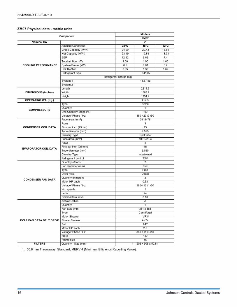
ZM07 Physical data - imperial units
ComponentModels
ZM07
Nominal Tonnage 6
COOLING PERFORMANCE
Ambient Conditions 95°F 118.4°F 125.6°F
Gross Capacity (BTU) 82182 69695 64467
Net Capacity (BTU) 80162 67685 62478
EER 12.32 8.62 7.4
Total air flow CFM 2110 2110 2110
System Power (kW) 6.5 8.01 8.7
Unit Kw/Ton 0.95 1.39 1.62
Refrigerant type R-410A
Refrigerant charge (lb-oz)
System 1 25 lbs. 12 oz.
System 2 -
DIMENSIONS (inches)
Length 87.2
Width 61.7
Height 48.6
OPERATING WT. (lbs.) 920
COMPRESSORS
Type Scroll
Quantity 1
Unit Capacity Steps (%) 100
Voltage/ Phase / Hz 380-420 /3 /50
CONDENSER COIL DATA
Face area (Sq. Ft.) 26
Rows 3
Fins per inch 13
Tube diameter (in.) 0.375
Circuitry Type Split face
EVAPORATOR COIL DATA
Face area (Sq. Ft.) 11.1
Rows 4
Fins per inch 15
Tube diameter 0.375
Circuitry Type Intertwined
Refrigerant control TXV
CONDENSER FAN DATA
Quantity of fans 2
Fan diameter (Inch) 22
Type Prop
Drive type Direct
Quantity of motors 2
Motor HP each 0.33
Voltage/ Phase / Hz 380-415 /1 /50
No. speeds 1
RPM 900
Nominal total CFM 6630
EVAP FAN DATABELT DRIVE
Airflow Option A
Quantity 1
Fan Size (Inch) 15 x 15
Type Centrifugal
Motor Sheave 1VP34
Blower Sheave AK74
Belt A47
Motor HP each 2.0
Voltage/ Phase / Hz 380-415 /3 /50
RPM 1425
Frame size 56Y
FILTERS Quantity - Size 4 - (20 x 20 x 2)1
1. 2 in. Throwaway, Standard, MERV 4 (Minimum Efficiency Reporting Value).
5543990-XTG-E-0719
16 Johnson Controls Ducted Systems
ZM07 Physical data - metric units
ComponentModels
ZM07
Nominal kW 21
COOLING PERFORMANCE
Ambient Conditions 35°C 48°C 52°C
Gross Capacity (kWh) 24.09 20.43 18.89
Net Capacity (kWh) 23.49 19.84 18.31
EER 12.32 8.62 7.4
Total air flow m³/s 1.00 1.00 1.00
System Power (kW) 6.5 8.01 8.7
Unit Kw/Ton 0.95 1.39 1.62
Refrigerant type R-410A
Refrigerant charge (kg)
System 1 11.67 kg
System 2 -
DIMENSIONS (inches)
Length 2214.9
Width 1567.2
Height 1234.4
OPERATING WT. (Kg.) 417.3
COMPRESSORS
Type Scroll
Quantity 1
Unit Capacity Steps (%) 100
Voltage/ Phase / Hz 380-420 /3 /50
CONDENSER COIL DATA
Face area (mm²) 2415478
Rows 3
Fins per inch (25mm) 13
Tube diameter (mm) 9.525
Circuitry Type Split face
EVAPORATOR COIL DATA
Face area (mm²) 1031223.3
Rows 4
Fins per inch (25 mm) 15
Tube diameter (mm) 9.525
Circuitry Type Intertwined
Refrigerant control TXV
CONDENSER FAN DATA
Quantity of fans 2
Fan diameter (mm) 559
Type Prop
Drive type Direct
Quantity of motors 2
Motor HP each 0.33
Voltage/ Phase / Hz 380-415 /1 /50
No. speeds 1
rad./s 94
Nominal total m³/s 3.13
EVAP FAN DATA BELT DRIVE
Airflow Option A
Quantity 1
Fan Size (mm) 381 x 381
Type Centrifugal
Motor Sheave 1VP34
Blower Sheave AK74
Belt A47
Motor HP each 2.0
Voltage/ Phase / Hz 380-415 /3 /50
rad./s 149
Frame size 56
FILTERS Quantity - Size (mm) 4 - (508 x 508 x 50.8)1
1. 50.8 mm Throwaway, Standard, MERV 4 (Minimum Efficiency Reporting Value).

5543990-XTG-E-0719
Johnson Controls Ducted Systems 17
ZM08 Physical data - imperial units
ComponentModels
ZM08
Nominal Tonnage 7.5
COOLING PERFORMANCE
Ambient Conditions 95°F 118.4°F 125.6°F
Gross Capacity (BTU) 100198 86269 78459
Net Capacity (BTU) 97641 83703 75876
EER 12.22 8.58 7.2
Total air flow CFM 2820 2820 2820
System Power (kW) 7.98 10.05 10.89
Unit Kw/Ton 0.96 1.4 1.67
Refrigerant type R-410A
Refrigerant charge (lb-oz)
System 1 27 lbs. 4 oz.
System 2 -
DIMENSIONS (inches)
Length 87.2
Width 61.7
Height 48.6
OPERATING WT. (lbs.) 960
COMPRESSORS
Type Scroll
Quantity 1
Unit Capacity Steps (%) 100
Voltage/ Phase / Hz 380-420 /3 /50
CONDENSER COIL DATA
Face area (Sq. Ft.) 26
Rows 3
Fins per inch 13
Tube diameter (in.) 0.375
Circuitry Type Split face
EVAPORATOR COIL DATA
Face area (Sq. Ft.) 11.1
Rows 4
Fins per inch 15
Tube diameter 0.375
Circuitry Type Intertwined
Refrigerant control TXV
CONDENSER FAN DATA
Quantity of fans 2
Fan diameter (Inch) 22
Type Prop
Drive type Direct
Quantity of motors 2
Motor HP each 0.33
Voltage/ Phase / Hz 380-415 /1 /50
No. speeds 1
RPM 900
Nominal total CFM 7310
EVAP FAN DATABELT DRIVE
Airflow Option A
Quantity 1
Fan Size (Inch) 15 x 15
Type Centrifugal
Motor Sheave 1VL44
Blower Sheave AK89
Belt A50
Motor HP each 2.0
Voltage/ Phase / Hz 380-415 /3 /50
RPM 1425
Frame size 56Y
FILTERS Quantity - Size 4 - (20 x 20 x 2)1
1. 2 in. Throwaway, Standard, MERV 4 (Minimum Efficiency Reporting Value).

5543990-XTG-E-0719
18 Johnson Controls Ducted Systems
ZM08 Physical data - metric units
ComponentModels
ZM08
Nominal kW 26
COOLING PERFORMANCE
Ambient Conditions 35°C 48°C 52°C
Gross Capacity (kWh) 29.37 25.28 22.99
Net Capacity (kWh) 28.62 24.53 22.24
EER 12.22 8.58 7.2
Total air flow m³/s 1.33 1.33 1.33
System Power (kW) 7.98 10.05 10.89
Unit Kw/Ton 0.96 1.4 1.67
Refrigerant type R-410A
Refrigerant charge (kg)
System 1 12.36
System 2 -
DIMENSIONS (inches)
Length 2214.9
Width 1567.2
Height 1234.4
OPERATING WT. (Kg.) 435.4
COMPRESSORS
Type Scroll
Quantity 1
Unit Capacity Steps (%) 100
Voltage/ Phase / Hz 380-420 /3 /50
CONDENSER COIL DATA
Face area (mm²) 2415478
Rows 3
Fins per inch (25mm) 13
Tube diameter (mm) 9.525
Circuitry Type Split face
EVAPORATOR COIL DATA
Face area (mm²) 1031223.3
Rows 4
Fins per inch (25 mm) 15
Tube diameter (mm) 9.525
Circuitry Type Intertwined
Refrigerant control TXV
CONDENSER FAN DATA
Quantity of fans 2
Fan diameter (mm) 559
Type Prop
Drive type Direct
Quantity of motors 2
Motor HP each 0.33
Voltage/ Phase / Hz 380-415 /1 /50
No. speeds 1
rad./s 94
Nominal total m³/s 3.45
EVAP FAN DATA BELT DRIVE
Airflow Option A
Quantity 1
Fan Size (mm) 381 x 381
Type Centrifugal
Motor Sheave 1VL44
Blower Sheave AK89
Belt A50
Motor HP each 2.0
Voltage/ Phase / Hz 380-415 /3 /50
rad./s 149
Frame size 56
FILTERS Quantity - Size (mm) 4 - (508 x 508 x 50.8)1
1. 50.8 mm Throwaway, Standard, MERV 4 (Minimum Efficiency Reporting Value).

5543990-XTG-E-0719
Johnson Controls Ducted Systems 19
Table 1: ZM05-08 unit limitations
ModelSize
(tons)Unit voltage
Unit limitations
Applied voltage Outdoor DB temp Outdoor DB temp
Minimum Maximum Maximum (°F) Maximum (°C)
ZM05(4)
380/415-3-50 342 457 125 52
ZM06(5)
380/415-3-50 342 457 125 52
ZM07(6)
380/415-3-50 342 457 125 52
ZM08
(7.5)380/415-3-50 342 457 125 52
5543990-XTG-E-0719
20 Johnson Controls Ducted Systems
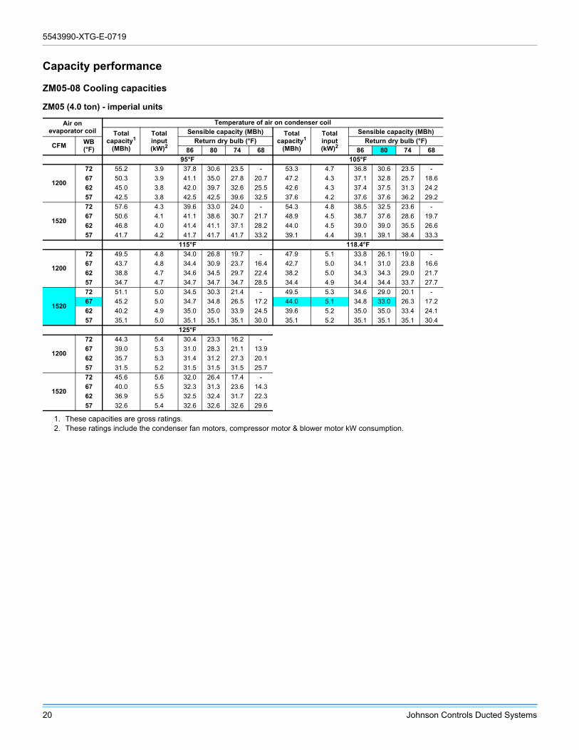
Capacity performance
ZM05-08 Cooling capacities
ZM05 (4.0 ton) - imperial units
Air onevaporator coil
Temperature of air on condenser coil
Totalcapacity1
(MBh)
Totalinput(kW)2
Sensible capacity (MBh) Totalcapacity1
(MBh)
Totalinput(kW)2
Sensible capacity (MBh)
CFMWB(°F)
Return dry bulb (°F) Return dry bulb (°F)
86 80 74 68 86 80 74 68
95°F 105°F
1200
72 55.2 3.9 37.8 30.6 23.5 - 53.3 4.7 36.8 30.6 23.5 -
67 50.3 3.9 41.1 35.0 27.8 20.7 47.2 4.3 37.1 32.8 25.7 18.6
62 45.0 3.8 42.0 39.7 32.6 25.5 42.6 4.3 37.4 37.5 31.3 24.2
57 42.5 3.8 42.5 42.5 39.6 32.5 37.6 4.2 37.6 37.6 36.2 29.2
1520
72 57.6 4.3 39.6 33.0 24.0 - 54.3 4.8 38.5 32.5 23.6 -
67 50.6 4.1 41.1 38.6 30.7 21.7 48.9 4.5 38.7 37.6 28.6 19.7
62 46.8 4.0 41.4 41.1 37.1 28.2 44.0 4.5 39.0 39.0 35.5 26.6
57 41.7 4.2 41.7 41.7 41.7 33.2 39.1 4.4 39.1 39.1 38.4 33.3
115°F 118.4°F
1200
72 49.5 4.8 34.0 26.8 19.7 - 47.9 5.1 33.8 26.1 19.0 -
67 43.7 4.8 34.4 30.9 23.7 16.4 42.7 5.0 34.1 31.0 23.8 16.6
62 38.8 4.7 34.6 34.5 29.7 22.4 38.2 5.0 34.3 34.3 29.0 21.7
57 34.7 4.7 34.7 34.7 34.7 28.5 34.4 4.9 34.4 34.4 33.7 27.7
1520
72 51.1 5.0 34.5 30.3 21.4 - 49.5 5.3 34.6 29.0 20.1 -
67 45.2 5.0 34.7 34.8 26.5 17.2 44.0 5.1 34.8 33.0 26.3 17.2
62 40.2 4.9 35.0 35.0 33.9 24.5 39.6 5.2 35.0 35.0 33.4 24.1
57 35.1 5.0 35.1 35.1 35.1 30.0 35.1 5.2 35.1 35.1 35.1 30.4
125°F
1200
72 44.3 5.4 30.4 23.3 16.2 -
67 39.0 5.3 31.0 28.3 21.1 13.9
62 35.7 5.3 31.4 31.2 27.3 20.1
57 31.5 5.2 31.5 31.5 31.5 25.7
1520
72 45.6 5.6 32.0 26.4 17.4 -
67 40.0 5.5 32.3 31.3 23.6 14.3
62 36.9 5.5 32.5 32.4 31.7 22.3
57 32.6 5.4 32.6 32.6 32.6 29.6
1. These capacities are gross ratings.2. These ratings include the condenser fan motors, compressor motor & blower motor kW consumption.

5543990-XTG-E-0719
Johnson Controls Ducted Systems 21
ZM05 (4.0 ton) - metric units
Air onevaporator coil
Temperature of air on condenser coil
Totalcapacity1
(kW)
Totalinput(kW)2
Sensible capacity (kW) Totalcapacity1
(kW)
Totalinput(kW)2
Sensible capacity (kW)
m3/sWB(°C)
Return dry bulb (°C) Return dry bulb (°C)
30 27 23 20 30 27 23 20
35° 41°C
0.57
22.2 16.2 3.9 11.1 9.0 6.9 - 15.6 4.7 10.8 9.0 6.9 -
19.4 14.7 3.9 12.0 10.3 8.2 6.1 13.8 4.3 10.9 9.6 7.5 5.4
16.7 13.2 3.8 12.3 11.6 9.6 7.5 12.5 4.3 11.0 11.0 9.2 7.1
13.9 12.5 3.8 12.5 12.5 11.6 9.5 11.0 4.2 11.0 11.0 10.6 8.5
0.72
22.2 16.9 4.3 11.6 9.7 7.0 - 15.9 4.8 11.3 9.5 6.9 -
19.4 14.8 4.1 12.0 11.3 9.0 6.4 14.3 4.5 11.3 11.0 8.4 5.8
16.7 13.7 4.0 12.1 12.0 10.9 8.3 12.9 4.5 11.4 11.4 10.4 7.8
13.9 12.2 4.2 12.2 12.2 12.2 9.7 11.5 4.4 11.5 11.5 11.3 9.8
46°C 48°C
0.57
22.2 14.5 4.8 10.0 7.9 5.8 - 14.0 5.1 9.9 7.6 5.6 -
19.4 12.8 4.8 10.1 9.0 6.9 4.8 12.5 5.0 10.0 9.1 7.0 4.9
16.7 11.4 4.7 10.1 10.1 8.7 6.6 11.2 5.0 10.1 10.1 8.5 6.4
13.9 10.2 4.7 10.2 10.2 10.2 8.3 10.1 4.9 10.1 10.1 9.9 8.1
0.72
22.2 15.0 5.0 10.1 8.9 6.3 - 14.5 5.3 10.1 8.5 5.9 -
19.4 13.3 5.0 10.2 10.2 7.8 5.1 12.9 5.1 10.2 9.7 7.7 5.0
16.7 11.8 4.9 10.3 10.3 9.9 7.2 11.6 5.2 10.3 10.3 9.8 7.1
13.9 10.3 5.0 10.3 10.3 10.3 8.8 10.3 5.2 10.3 10.3 10.3 8.9
52°C
0.57
22.2 13.0 5.4 8.9 6.8 4.7 -
19.4 11.4 5.3 9.1 8.3 6.2 4.1
16.7 10.5 5.3 9.2 9.1 8.0 5.9
13.9 9.2 5.2 9.2 9.2 9.2 7.5
0.72
22.2 13.4 5.6 9.4 7.7 5.1 -
19.4 11.7 5.5 9.5 9.2 6.9 4.2
16.7 10.8 5.5 9.5 9.5 9.3 6.5
13.9 9.6 5.4 9.6 9.6 9.6 8.7
0.72
22.2 13.4 5.6 10.4 7.7 5.1 -
19.4 11.7 5.5 11.3 9.2 6.9 4.2
16.7 10.8 5.5 10.8 10.7 9.3 6.5
13.9 9.6 5.4 9.6 9.6 9.6 8.7
1. These capacities are gross ratings.2. These ratings include the condenser fan motors, compressor motor & blower motor kW consumption.
5543990-XTG-E-0719
22 Johnson Controls Ducted Systems
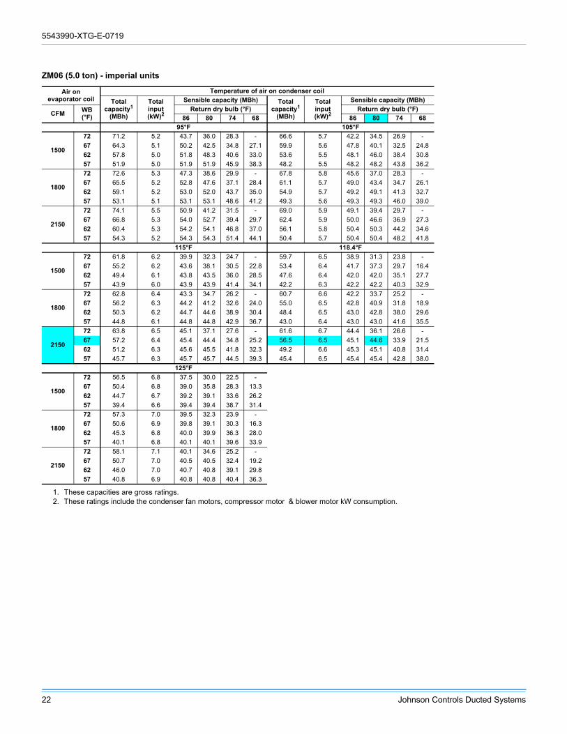
ZM06 (5.0 ton) - imperial units
Air onevaporator coil
Temperature of air on condenser coil
Totalcapacity1
(MBh)
Totalinput(kW)2
Sensible capacity (MBh) Totalcapacity1
(MBh)
Totalinput(kW)2
Sensible capacity (MBh)
CFMWB(°F)
Return dry bulb (°F) Return dry bulb (°F)
86 80 74 68 86 80 74 68
95°F 105°F
1500
72 71.2 5.2 43.7 36.0 28.3 - 66.6 5.7 42.2 34.5 26.9 -
67 64.3 5.1 50.2 42.5 34.8 27.1 59.9 5.6 47.8 40.1 32.5 24.8
62 57.8 5.0 51.8 48.3 40.6 33.0 53.6 5.5 48.1 46.0 38.4 30.8
57 51.9 5.0 51.9 51.9 45.9 38.3 48.2 5.5 48.2 48.2 43.8 36.2
1800
72 72.6 5.3 47.3 38.6 29.9 - 67.8 5.8 45.6 37.0 28.3 -
67 65.5 5.2 52.8 47.6 37.1 28.4 61.1 5.7 49.0 43.4 34.7 26.1
62 59.1 5.2 53.0 52.0 43.7 35.0 54.9 5.7 49.2 49.1 41.3 32.7
57 53.1 5.1 53.1 53.1 48.6 41.2 49.3 5.6 49.3 49.3 46.0 39.0
2150
72 74.1 5.5 50.9 41.2 31.5 - 69.0 5.9 49.1 39.4 29.7 -
67 66.8 5.3 54.0 52.7 39.4 29.7 62.4 5.9 50.0 46.6 36.9 27.3
62 60.4 5.3 54.2 54.1 46.8 37.0 56.1 5.8 50.4 50.3 44.2 34.6
57 54.3 5.2 54.3 54.3 51.4 44.1 50.4 5.7 50.4 50.4 48.2 41.8
115°F 118.4°F
1500
72 61.8 6.2 39.9 32.3 24.7 - 59.7 6.5 38.9 31.3 23.8 -
67 55.2 6.2 43.6 38.1 30.5 22.8 53.4 6.4 41.7 37.3 29.7 16.4
62 49.4 6.1 43.8 43.5 36.0 28.5 47.6 6.4 42.0 42.0 35.1 27.7
57 43.9 6.0 43.9 43.9 41.4 34.1 42.2 6.3 42.2 42.2 40.3 32.9
1800
72 62.8 6.4 43.3 34.7 26.2 - 60.7 6.6 42.2 33.7 25.2 -
67 56.2 6.3 44.2 41.2 32.6 24.0 55.0 6.5 42.8 40.9 31.8 18.9
62 50.3 6.2 44.7 44.6 38.9 30.4 48.4 6.5 43.0 42.8 38.0 29.6
57 44.8 6.1 44.8 44.8 42.9 36.7 43.0 6.4 43.0 43.0 41.6 35.5
2150
72 63.8 6.5 45.1 37.1 27.6 - 61.6 6.7 44.4 36.1 26.6 -
67 57.2 6.4 45.4 44.4 34.8 25.2 56.5 6.5 45.1 44.6 33.9 21.5
62 51.2 6.3 45.6 45.5 41.8 32.3 49.2 6.6 45.3 45.1 40.8 31.4
57 45.7 6.3 45.7 45.7 44.5 39.3 45.4 6.5 45.4 45.4 42.8 38.0
125°F
1500
72 56.5 6.8 37.5 30.0 22.5 -
67 50.4 6.8 39.0 35.8 28.3 13.3
62 44.7 6.7 39.2 39.1 33.6 26.2
57 39.4 6.6 39.4 39.4 38.7 31.4
1800
72 57.3 7.0 39.5 32.3 23.9 -
67 50.6 6.9 39.8 39.1 30.3 16.3
62 45.3 6.8 40.0 39.9 36.3 28.0
57 40.1 6.8 40.1 40.1 39.6 33.9
2150
72 58.1 7.1 40.1 34.6 25.2 -
67 50.7 7.0 40.5 40.5 32.4 19.2
62 46.0 7.0 40.7 40.8 39.1 29.8
57 40.8 6.9 40.8 40.8 40.4 36.3
1. These capacities are gross ratings.2. These ratings include the condenser fan motors, compressor motor & blower motor kW consumption.

5543990-XTG-E-0719
Johnson Controls Ducted Systems 23
ZM06 (5.0 ton) - metric units
Air onevaporator coil
Temperature of air on condenser coil
Totalcapacity1
(kW)
Totalinput(kW)2
Sensible capacity (kW) Totalcapacity1
(kW)
Totalinput(kW)2
Sensible capacity (kW)
m3/sWB(°C)
Return dry bulb (°C) Return dry bulb (°C)
30 27 23 20 30 27 23 20
35° 41°C
0.71
22.2 20.9 5.2 12.8 10.5 8.3 - 19.5 5.7 12.4 10.1 7.9 -
19.4 18.8 5.1 14.7 12.5 10.2 8.0 17.6 5.6 14.0 11.8 9.5 7.3
16.7 16.9 5.0 15.2 14.1 11.9 9.7 15.7 5.5 14.1 13.5 11.3 9.0
13.9 15.2 5.0 15.2 15.2 13.5 11.2 14.1 5.5 14.1 14.1 12.8 10.6
0.85
22.2 21.3 5.3 13.9 11.3 8.8 - 19.9 5.8 13.4 10.8 8.3 -
19.4 19.2 5.2 15.5 13.9 10.9 8.3 17.9 5.7 14.4 12.7 10.2 7.6
16.7 17.3 5.2 15.5 15.2 12.8 10.3 16.1 5.7 14.4 14.4 12.1 9.6
13.9 15.6 5.1 15.6 15.6 14.3 12.1 14.5 5.6 14.5 14.5 13.5 11.4
1.01
22.2 21.7 5.5 14.9 12.1 9.2 - 20.2 5.9 14.4 11.5 8.7 -
19.4 19.6 5.3 15.8 15.4 11.5 8.7 18.3 5.9 14.7 13.7 10.8 8.0
16.7 17.7 5.3 15.9 15.9 13.7 10.9 16.4 5.8 14.8 14.7 13.0 10.1
13.9 15.9 5.2 15.9 15.9 15.0 12.9 14.8 5.7 14.8 14.8 14.1 12.2
46°C 48°C
0.71
22.2 18.1 6.2 11.7 9.5 7.3 - 17.5 6.5 11.4 9.2 7.0 -
19.4 16.2 6.2 12.8 11.2 8.9 6.7 15.7 6.4 12.2 10.9 8.7 4.8
16.7 14.5 6.1 12.8 12.7 10.5 8.4 13.9 6.4 12.3 12.3 10.3 8.1
13.9 12.9 6.0 12.9 12.9 12.1 10.0 12.4 6.3 12.4 12.4 11.8 9.7
0.85
22.2 18.4 6.4 12.7 10.2 7.7 - 17.8 6.6 12.4 9.9 7.4 -
19.4 16.5 6.3 13.0 12.1 9.6 7.0 16.1 6.5 12.5 12.0 9.3 5.5
16.7 14.7 6.2 13.1 13.1 11.4 8.9 14.2 6.5 12.6 12.5 11.1 8.7
13.9 13.1 6.1 13.1 13.1 12.6 10.8 12.6 6.4 12.6 12.6 12.2 10.4
1.01
22.2 18.7 6.5 13.2 10.9 8.1 - 18.1 6.7 13.0 10.6 7.8 -
19.4 16.8 6.4 13.3 13.0 10.2 7.4 16.6 6.5 13.2 13.1 9.9 6.3
16.7 15.0 6.3 13.4 13.3 12.2 9.5 14.4 6.6 13.3 13.2 12.0 9.2
13.9 13.4 6.3 13.4 13.4 13.0 11.5 13.3 6.5 13.3 13.3 12.5 11.1
52°C
0.71
22.2 16.6 6.8 11.0 8.8 6.6 -
19.4 14.8 6.8 11.4 10.5 8.3 3.9
16.7 13.1 6.7 11.5 11.5 9.8 7.7
13.9 11.6 6.6 11.6 11.6 11.3 9.2
0.85
22.2 16.8 7.0 11.6 9.5 7.0 -
19.4 14.8 6.9 11.7 11.4 8.9 4.8
16.7 13.3 6.8 11.7 11.7 10.6 8.2
13.9 11.8 6.8 11.8 11.8 11.6 9.9
1.01
22.2 17.0 7.1 11.8 10.1 7.4 -
19.4 14.9 7.0 11.9 11.9 9.5 5.6
16.7 13.5 7.0 11.9 12.0 11.5 8.7
13.9 12.0 6.9 12.0 12.0 11.8 10.6
1. These capacities are gross ratings.2. These ratings include the condenser fan motors, compressor motor & blower motor kW consumption.
5543990-XTG-E-0719
24 Johnson Controls Ducted Systems
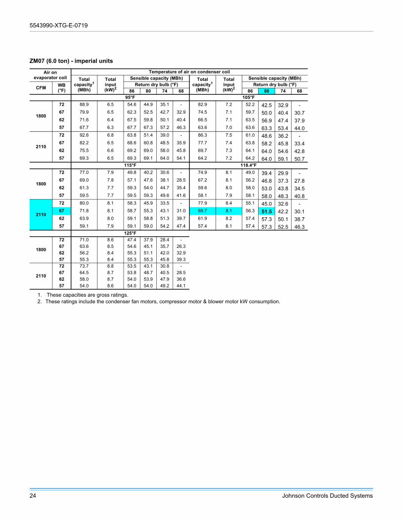
ZM07 (6.0 ton) - imperial units
Air onevaporator coil
Temperature of air on condenser coil
Totalcapacity1
(MBh)
Totalinput(kW)2
Sensible capacity (MBh) Totalcapacity1
(MBh)
Totalinput(kW)2
Sensible capacity (MBh)
CFMWB(°F)
Return dry bulb (°F) Return dry bulb (°F)
86 80 74 68 86 80 74 68
95°F 105°F
1800
72 88.9 6.5 54.6 44.9 35.1 - 82.9 7.2 52.2 42.5 32.9 -67 79.9 6.5 62.3 52.5 42.7 32.9 74.5 7.1 59.7 50.0 40.4 30.762 71.6 6.4 67.5 59.8 50.1 40.4 66.5 7.1 63.5 56.9 47.4 37.957 67.7 6.3 67.7 67.3 57.2 46.3 63.6 7.0 63.6 63.3 53.4 44.0
2110
72 92.6 6.8 63.8 51.4 39.0 - 86.3 7.5 61.0 48.6 36.2 -67 82.2 6.5 68.6 60.8 48.5 35.9 77.7 7.4 63.8 58.2 45.8 33.462 75.5 6.6 69.2 69.0 58.0 45.8 69.7 7.3 64.1 64.0 54.6 42.857 69.3 6.5 69.3 69.1 64.0 54.1 64.2 7.2 64.2 64.0 59.1 50.7
115°F 118.4°F
1800
72 77.0 7.9 49.8 40.2 30.6 - 74.9 8.1 49.0 39.4 29.9 -67 69.0 7.8 57.1 47.6 38.1 28.5 67.2 8.1 56.2 46.8 37.3 27.862 61.3 7.7 59.3 54.0 44.7 35.4 59.6 8.0 58.0 53.0 43.8 34.557 59.5 7.7 59.5 59.3 49.6 41.6 58.1 7.9 58.1 58.0 48.3 40.8
2110
72 80.0 8.1 58.3 45.9 33.5 - 77.9 8.4 55.1 45.0 32.6 -67 71.8 8.1 58.7 55.3 43.1 31.0 69.7 8.1 56.3 51.5 42.2 30.162 63.9 8.0 59.1 58.8 51.3 39.7 61.9 8.2 57.4 57.3 50.1 38.757 59.1 7.9 59.1 59.0 54.2 47.4 57.4 8.1 57.4 57.3 52.5 46.3
125°F
1800
72 71.0 8.6 47.4 37.9 28.4 -
67 63.6 8.5 54.6 45.1 35.7 26.3
62 56.2 8.4 55.3 51.1 42.0 32.9
57 55.3 8.4 55.3 55.3 45.8 39.3
2110
72 73.7 8.8 53.5 43.1 30.8 -
67 64.5 8.7 53.8 48.7 40.5 28.5
62 58.0 8.7 54.0 53.9 47.9 36.6
57 54.0 8.6 54.0 54.0 49.2 44.1
1. These capacities are gross ratings.2. These ratings include the condenser fan motors, compressor motor & blower motor kW consumption.
5543990-XTG-E-0719
Johnson Controls Ducted Systems 25
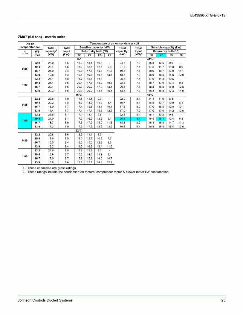
ZM07 (6.0 ton) - metric units
Air onevaporator coil
Temperature of air on condenser coil
Totalcapacity1
(kW)
Totalinput(kW)2
Sensible capacity (kW) Totalcapacity1
(kW)
Totalinput(kW)2
Sensible capacity (kW)
m3/sWB(°C)
Return dry bulb (°C) Return dry bulb (°C)
30 27 23 20 30 27 23 20
35° 41°C
0.85
22.2 26.0 6.5 16.0 13.1 10.3 - 24.3 7.2 15.3 12.5 9.6 -
19.4 23.4 6.5 18.2 15.4 12.5 9.6 21.8 7.1 17.5 14.7 11.8 9.0
16.7 21.0 6.4 19.8 17.5 14.7 11.8 19.5 7.1 18.6 16.7 13.9 11.1
13.9 19.8 6.3 19.8 19.7 16.8 13.6 18.6 7.0 18.6 18.5 15.6 12.9
1.00
22.2 27.1 6.8 18.7 15.1 11.4 - 25.3 7.5 17.9 14.3 10.6 -
19.4 24.1 6.5 20.1 17.8 14.2 10.5 22.8 7.4 18.7 17.0 13.4 9.8
16.7 22.1 6.6 20.3 20.2 17.0 13.4 20.4 7.3 18.8 18.8 16.0 12.5
13.9 20.3 6.5 20.3 20.2 18.8 15.8 18.8 7.2 18.8 18.8 17.3 14.9
46°C 48°C
0.85
22.2 22.6 7.9 14.6 11.8 9.0 - 22.0 8.1 14.4 11.6 8.8 -
19.4 20.2 7.8 16.7 13.9 11.2 8.4 19.7 8.1 16.5 13.7 10.9 8.1
16.7 18.0 7.7 17.4 15.8 13.1 10.4 17.5 8.0 17.0 15.5 12.8 10.1
13.9 17.4 7.7 17.4 17.4 14.5 12.2 17.0 7.9 17.0 17.0 14.2 12.0
1.00
22.2 23.5 8.1 17.1 13.4 9.8 - 22.8 8.4 16.1 13.2 9.5 -
19.4 21.0 8.1 17.2 16.2 12.6 9.1 20.4 8.1 16.5 15.1 12.4 8.8
16.7 18.7 8.0 17.3 17.2 15.0 11.6 18.1 8.2 16.8 16.8 14.7 11.3
13.9 17.3 7.9 17.3 17.3 15.9 13.9 16.8 8.1 16.8 16.8 15.4 13.6
52°C
0.85
22.2 20.8 8.6 13.9 11.1 8.3 -
19.4 18.6 8.5 16.0 13.2 10.5 7.7
16.7 16.5 8.4 16.2 15.0 12.3 9.6
13.9 16.2 8.4 16.2 16.2 13.4 11.5
1.00
22.2 21.6 8.8 15.7 12.6 9.0 -
19.4 18.9 8.7 15.8 14.3 11.9 8.4
16.7 17.0 8.7 15.8 15.8 14.0 10.7
13.9 15.8 8.6 15.8 15.8 14.4 12.9
1. These capacities are gross ratings.2. These ratings include the condenser fan motors, compressor motor & blower motor kW consumption.

5543990-XTG-E-0719
26 Johnson Controls Ducted Systems
ZM08 (7.5 ton) - imperial units
Air onevaporator coil
Temperature of air on condenser coil
Totalcapacity1
(MBh)
Totalinput(kW)2
Sensible capacity (MBh) Totalcapacity1
(MBh)
Totalinput(kW)2
Sensible capacity (MBh)
CFMWB(°F)
Return dry bulb (°F) Return dry bulb (°F)
86 80 74 68 86 80 74 68
95°F 105°F
2250
72 105.2 8.0 65.8 55.0 44.2 - 98.3 8.9 62.8 52.0 41.2 -
67 96.2 7.9 74.6 63.5 52.5 41.4 89.3 8.8 70.9 60.0 49.2 38.3
62 86.2 7.8 76.1 71.8 60.7 49.7 79.7 8.7 72.4 67.7 57.1 46.4
57 76.2 7.7 76.2 76.1 65.9 56.7 72.6 8.6 72.6 72.5 62.1 53.5
2550
72 107.6 8.1 69.9 57.9 46.0 - 100.8 9.0 66.8 54.8 42.7 -
67 98.2 8.0 80.0 68.5 55.0 42.5 92.0 8.9 76.2 64.1 51.7 39.4
62 89.3 7.9 81.7 77.2 64.7 52.1 82.4 8.8 76.3 72.6 61.0 48.8
57 81.7 7.9 81.7 81.3 69.2 60.6 76.3 8.8 76.3 76.0 65.2 57.3
2820
72 110.1 8.3 73.9 60.8 47.7 - 103.3 9.2 70.9 57.6 44.2 -
67 100.2 8.0 85.5 73.5 57.6 43.7 94.7 9.1 78.9 68.1 54.3 40.5
62 92.3 8.1 87.0 82.7 68.7 54.6 85.1 9.0 79.7 77.5 64.9 51.3
57 87.1 8.1 87.1 86.5 72.5 64.4 79.9 8.9 79.9 79.5 68.4 61.1
115°F 118.4°F
2250
72 91.4 9.8 59.7 49.0 38.3 - 89.0 10.1 58.7 48.0 37.3 -
67 82.4 9.7 67.2 56.5 45.9 35.2 80.1 10.0 65.9 55.3 44.7 34.2
62 73.2 9.5 68.9 63.7 53.4 43.1 71.0 9.8 67.5 62.4 52.2 42.0
57 69.0 9.5 69.0 69.0 58.4 50.4 67.8 9.8 67.8 67.7 57.1 49.4
2550
72 93.9 9.9 63.8 51.6 39.5 - 91.6 10.2 62.7 50.6 38.4 -
67 84.9 9.8 70.5 60.6 48.4 36.3 83.2 10.0 67.7 59.4 47.3 35.2
62 75.6 9.7 70.8 68.0 57.3 45.5 73.2 10.0 68.8 66.5 56.1 44.4
57 70.8 9.6 70.8 70.7 61.3 54.1 69.0 9.9 69.0 68.9 60.0 53.0
2820
72 96.5 10.0 67.8 54.3 40.8 - 94.1 10.3 66.8 53.2 39.6 -
67 87.5 9.9 71.9 64.7 51.0 37.3 86.3 10.1 69.8 63.4 49.9 36.2
62 77.9 9.8 72.5 72.4 61.2 47.9 75.5 10.1 70.1 70.1 60.0 46.8
57 72.7 9.8 72.7 72.5 64.2 57.8 70.2 10.1 70.2 70.1 62.8 56.7
125°F
2250
72 84.5 10.7 56.7 46.0 35.3 -
67 75.5 10.6 63.5 53.0 42.6 32.1
62 66.7 10.4 65.3 59.7 49.8 39.8
57 65.4 10.3 65.4 65.4 54.6 47.3
2550
72 87.0 10.8 60.7 48.5 36.3 -
67 77.0 10.7 65.1 56.3 45.1 33.1
62 68.7 10.5 65.3 63.5 53.6 42.2
57 65.4 10.5 65.4 65.4 57.4 50.9
2820
72 89.6 10.9 64.8 51.0 37.3 -
67 78.5 10.9 65.0 59.6 47.7 34.2
62 70.7 10.7 65.3 65.4 57.5 44.6
57 65.5 10.7 65.5 65.5 60.1 54.5
1. These capacities are gross ratings.2. These ratings include the condenser fan motors, compressor motor & blower motor kW consumption.

5543990-XTG-E-0719
Johnson Controls Ducted Systems 27
ZM08 (7.5 ton) - metric units
Air onevaporator coil
Temperature of air on condenser coil
Totalcapacity1
(kW)
Totalinput(kW)2
Sensible capacity (kW) Totalcapacity1
(kW)
Totalinput(kW)2
Sensible capacity (kW)
m3/sWB(°C)
Return dry bulb (°C) Return dry bulb (°C)
30 27 23 20 30 27 23 20
35° 41°C
1.06
22.2 30.8 8.0 19.3 16.1 12.9 - 28.8 8.9 18.4 15.2 12.1 -
19.4 28.2 7.9 21.8 18.6 15.4 12.1 26.2 8.8 20.8 17.6 14.4 11.2
16.7 25.3 7.8 22.3 21.0 17.8 14.6 23.4 8.7 21.2 19.9 16.7 13.6
13.9 22.3 7.7 22.3 22.3 19.3 16.6 21.3 8.6 21.3 21.3 18.2 15.7
1.20
22.2 31.5 8.1 20.5 17.0 13.5 - 29.5 9.0 19.6 16.1 12.5 -
19.4 28.8 8.0 23.4 20.1 16.1 12.5 27.0 8.9 22.3 18.8 15.2 11.5
16.7 26.2 7.9 23.9 22.6 19.0 15.3 24.2 8.8 22.4 21.3 17.9 14.3
13.9 23.9 7.9 23.9 23.8 20.3 17.7 22.3 8.8 22.3 22.3 19.1 16.8
1.33
22.2 32.3 8.3 21.7 17.8 14.0 - 30.3 9.2 20.8 16.9 13.0 -
19.4 29.4 8.0 25.0 21.6 16.9 12.8 27.8 9.1 23.1 20.0 15.9 11.9
16.7 27.1 8.1 25.5 24.2 20.1 16.0 24.9 9.0 23.4 22.7 19.0 15.0
13.9 25.5 8.1 25.5 25.4 21.2 18.9 23.4 8.9 23.4 23.3 20.0 17.9
46°C 48°C
1.06
22.2 26.8 9.8 17.5 14.4 11.2 - 26.1 10.1 17.2 14.1 10.9 -
19.4 24.1 9.7 19.7 16.6 13.4 10.3 23.5 10.0 19.3 16.2 13.1 10.0
16.7 21.5 9.5 20.2 18.7 15.7 12.6 20.8 9.8 19.8 18.3 15.3 12.3
13.9 20.2 9.5 20.2 20.2 17.1 14.8 19.9 9.8 19.9 19.9 16.7 14.5
1.20
22.2 27.5 9.9 18.7 15.1 11.6 - 26.8 10.2 18.4 14.8 11.3 -
19.4 24.9 9.8 20.7 17.8 14.2 10.6 24.4 10.0 19.8 17.4 13.9 10.3
16.7 22.1 9.7 20.7 19.9 16.8 13.3 21.5 10.0 20.2 19.5 16.4 13.0
13.9 20.8 9.6 20.8 20.7 18.0 15.9 20.2 9.9 20.2 20.2 17.6 15.5
1.33
22.2 28.3 10.0 19.9 15.9 11.9 - 27.6 10.3 19.6 15.6 11.6 -
19.4 25.6 9.9 21.1 19.0 15.0 10.9 25.3 10.1 20.5 18.6 14.6 10.6
16.7 22.8 9.8 21.2 21.2 17.9 14.0 22.1 10.1 20.5 20.5 17.6 13.7
13.9 21.3 9.8 21.3 21.2 18.8 17.0 20.6 10.1 20.6 20.6 18.4 16.6
52°C
1.06
22.2 24.8 10.7 16.6 13.5 10.3 -
19.4 22.1 10.6 18.6 15.5 12.5 9.4
16.7 19.5 10.4 19.1 17.5 14.6 11.7
13.9 19.2 10.3 19.2 19.2 16.0 13.9
1.20
22.2 25.5 10.8 17.8 14.2 10.6 -
19.4 22.6 10.7 19.1 16.5 13.2 9.7
16.7 20.1 10.5 19.1 18.6 15.7 12.4
13.9 19.2 10.5 19.2 19.2 16.8 14.9
1.33
22.2 26.3 10.9 19.0 15.0 10.9 -
19.4 23.0 10.9 19.0 17.5 14.0 10.0
16.7 20.7 10.7 19.1 19.2 16.9 13.1
13.9 19.2 10.7 19.2 19.2 17.6 16.0
1. These capacities are gross ratings.2. These ratings include the condenser fan motors, compressor motor & blower motor kW consumption.

5543990-XTG-E-0719
28 Johnson Controls Ducted Systems
Drive selection
1. Determine side supply duct application.
2. Determine the desired airflow.
3. Calculate or measure the amount of external static pressure.
• Add or deduct any additional static resistance from the “Additional Static Resistance” table.4. Using the operating point determined from steps 1, 2 & 3, locate this point on the appropriate supply air blower performance
table. (Linear interpolation may be necessary.)
5. Noting the RPM and BHP from step 4, locate the appropriate motor and, or drive on the RPM selection table.
6. Review the BHP compared to the motor options available. Select the appropriate motor and, or drive.
7. Review the RPM range for the motor options available. Select the appropriate drive if multiple drives are available for the chosen motor.
8. Determine turns open to obtain the desired operation point.
Example
1. 3200 SCFM, Bottom Supply Duct application
2. 1.8 IWG
3. Using the airflow performance table below, the following data point was located: 1071 RPM & 2.52 BHP.
4. Using the RPM selection table below, Model ZY and Size 08 (7.5 Tons) is found.
5. 2.52 BHP exceeds the maximum continuous BHP rating of the 2.4 HP motor. The 3.7 HP motor is required.
6. 1071 RPM is within the range of the 3.7 HP motor.
7. Using the 3.7-HP motor and High-Static drive, 0.5 turns open will achieve the required 1071 RPM.
Airflow performance
Example supply air blower performance
CFMAvailable external static, IWG
0.2 0.4 0.6 0.8 1.0 1.2 1.4 1.6 1.8 2.0RPM BHP RPM BHP RPM BHP RPM BHP RPM BHP RPM BHP RPM BHP RPM BHP RPM BHP RPM BHP
2250 556 0.45 621 0.65 683 0.83 742 1.00 798 1.18 852 1.34 904 1.51 954 1.69 1003 1.87 1050 2.06
2400 567 0.53 632 0.73 694 0.91 753 1.09 809 1.26 863 1.43 914 1.60 964 1.77 1013 1.95 1060 2.14
2600 580 0.65 646 0.85 707 1.03 766 1.21 823 1.38 876 1.55 928 1.72 978 1.89 1027 2.07 1074 2.27
2800 595 0.79 660 0.99 722 1.17 780 1.35 837 1.52 890 1.69 942 1.86 992 2.03 1041 2.21 1088 2.40
3000 609 0.94 674 1.14 736 1.32 795 1.50 851 1.67 905 1.83 957 2.00 1007 2.18 1056 2.36 1100 2.55
3200 625 1.10 690 1.30 752 1.48 810 1.66 867 1.83 921 2.00 972 2.17 1022 2.34 1071 2.52 -- --
3400 641 1.28 706 1.47 768 1.66 827 1.83 883 2.00 937 2.17 989 2.34 1039 2.52 1087 2.70 '-- --
Standard static option with motor rated at 2.4-hpMedium static option with motor rated at 2.4-hpHigh static option with motor rated at 3.7-hp
-- Exceeds recommended blower speed
Example RPM Selection
ModelSize
(tons)Airflowoption
PhaseMaxBHP
Blower sheave
Motor sheave
6 turns open
5 turns open
4 turns open
3 turns open
2 turns open
1 turn open
Fully closed
ZY08
(7.5)
Std. 3 2.4 AK74 1VL34 N/A 475 525 575 625 675 725Med. 3 2.4 AK74 1VL44 N/A 700 750 800 850 900 950
H. Static 3 3.7 AK74 1VP50 N/A 850 900 950 1000 1050 1100
5543990-XTG-E-0719
Johnson Controls Ducted Systems 29
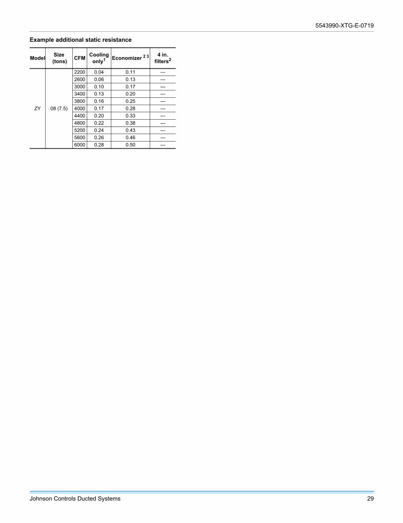
Example additional static resistance
ModelSize
(tons)CFM
Coolingonly1 Economizer 2 3 4 in.
filters2
ZY 08 (7.5)
2200 0.04 0.11 ---
2600 0.06 0.13 ---
3000 0.10 0.17 ---
3400 0.13 0.20 ---
3800 0.16 0.25 ---
4000 0.17 0.28 ---
4400 0.20 0.33 ---
4800 0.22 0.38 ---
5200 0.24 0.43 ---
5600 0.26 0.46 ---
6000 0.28 0.50 ---

5543990-XTG-E-0719
30 Johnson Controls Ducted Systems
Altitude and temperature correction for CFM, static pressure and power
The information below should be used to assist in application of product when being applied at altitudes at or exceeding 1000 feet above sea level.
The air flow rates listed in the standard blower performance tables are based on standard air at sea level. As the altitude or temperature increases, the density of air decreases. In order to
use the indoor blower tables for high altitude applications, certain corrections are necessary.
A centrifugal fan is a constant volume device. This means that, if the RPM remains constant, the CFM delivered is the same regardless of the density of the air. However, since the air at high altitude is less dense, less static pressure is generated and less power is required than a similar application at sea level. Air density correction factors are shown below.
Use the examples below to assist in determining the airflow performance of the product at altitude.
Example 1: What are the corrected CFM, static pressure, and BHP at an elevation of 5,000 ft. if the airflow performance data is 3,000 CFM, 1.4 IWC and 2.0 BHP?
Solution: At an elevation of 5,000 ft. the indoor blower will still deliver 3,000 CFM if the RPM is unchanged. However, the altitude correction must be used to determine the static pressure and BHP. Since no temperature data is given, we assume an air temperature of 70°F. The Altitude/Temperature Factors show the correction factor to be 0.832.
Corrected static pressure = 1.4 x 0.832 = 1.16 IWC
Corrected BHP = 2.0 x 0.832 = 1.66Example 2: A system, located at 5,000 feet of elevation, is to deliver 3,000 CFM at a static pressure of 1.4 inches. Use the
unit blower tables to select the blower speed and the BHP requirement.
Solution: As in the example above, no temperature information is given so 70°F is assumed.
The 1.4-inch static pressure given is at an elevation of 5,000 ft. The first step is to convert this static pressure to equivalent sea level conditions.
Sea level static pressure = 1.4 in. / .832 = 1.68 in.
Enter the Supply Air Blower Performance Table at 3,000 CFM and static pressure of 1.68 inches. The RPM listed is the same RPM needed at 5,000 ft.
Suppose that the corresponding BHP listed in the table is 2.0.This value must be corrected for elevation.
BHP at 5,000 ft. = 2.0 x .832 = 1.66
Altitude/temperature correction factors
Airtemp.
Altitude (ft.)0 1000 2000 3000 4000 5000 6000 7000 8000 9000 10000
40 1.060 1.022 0.986 0.950 0.916 0.882 0.849 0.818 0.788 0.758 0.72950 1.039 1.002 0.966 0.931 0.898 0.864 0.832 0.802 0.772 0.743 0.71560 1.019 0.982 0.948 0.913 0.880 0.848 0.816 0.787 0.757 0.729 0.70170 1.000 0.964 0.930 0.896 0.864 0.832 0.801 0.772 0.743 0.715 0.68880 0.982 0.947 0.913 0.880 0.848 0.817 0.787 0.758 0.730 0.702 0.67690 0.964 0.929 0.897 0.864 0.833 0.802 0.772 0.744 0.716 0.689 0.663
100 0.946 0.912 0.880 0.848 0.817 0.787 0.758 0.730 0.703 0.676 0.651
0.600
0.650
0.700
0.750
0.800
0.850
0.900
0.950
1.000
1.050
1.100
40 50 60 70 80 90 100Air Temperature (ºF)
Cor
rect
ion
Fact
or
Sea Level
1000 ft
2000 ft
3000 ft
4000 ft
6000 ft7000 ft
8000 ft9000 ft10000 ft
5000 ft
5543990-XTG-E-0719
Johnson Controls Ducted Systems 31
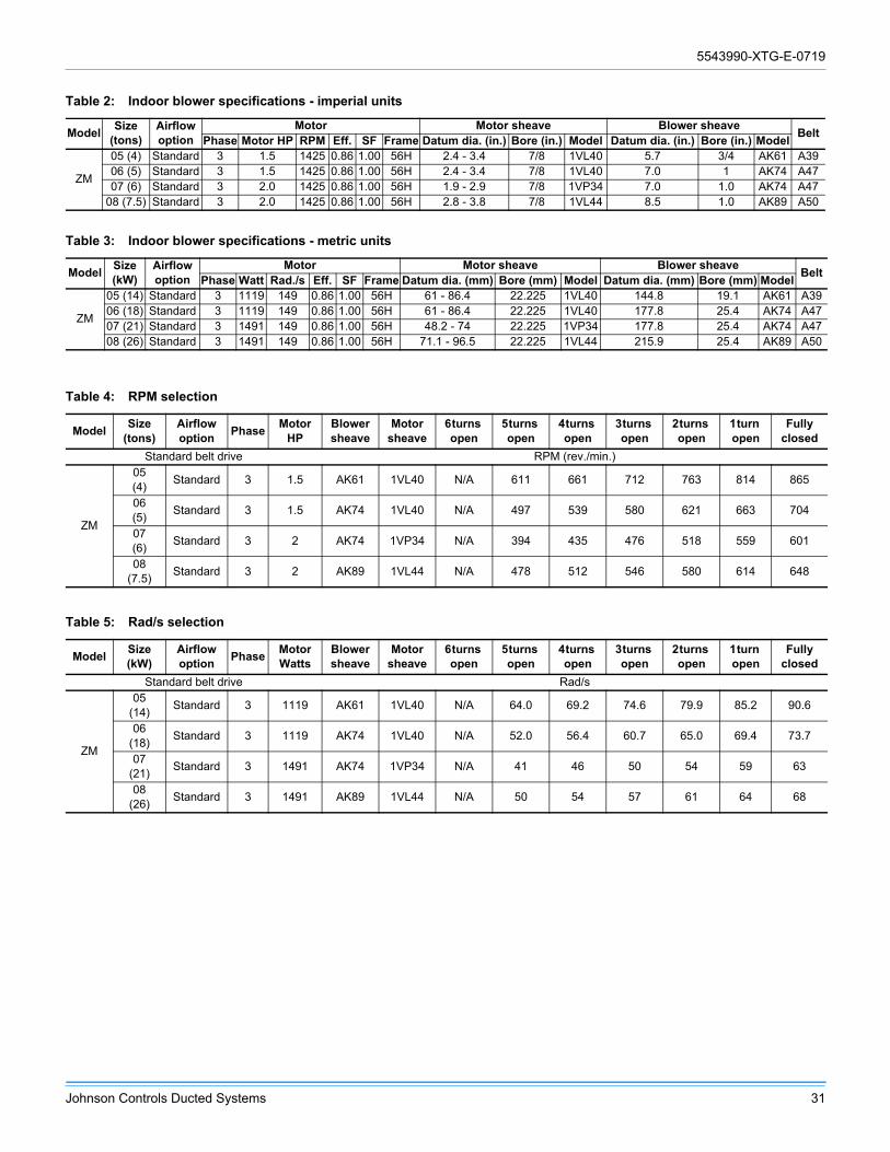
Table 2: Indoor blower specifications - imperial units
ModelSize
(tons)Airflow option
Motor Motor sheave Blower sheaveBelt
Phase Motor HP RPM Eff. SF Frame Datum dia. (in.) Bore (in.) Model Datum dia. (in.) Bore (in.) Model
ZM
05 (4) Standard 3 1.5 1425 0.86 1.00 56H 2.4 - 3.4 7/8 1VL40 5.7 3/4 AK61 A3906 (5) Standard 3 1.5 1425 0.86 1.00 56H 2.4 - 3.4 7/8 1VL40 7.0 1 AK74 A4707 (6) Standard 3 2.0 1425 0.86 1.00 56H 1.9 - 2.9 7/8 1VP34 7.0 1.0 AK74 A47
08 (7.5) Standard 3 2.0 1425 0.86 1.00 56H 2.8 - 3.8 7/8 1VL44 8.5 1.0 AK89 A50
Table 3: Indoor blower specifications - metric units
ModelSize (kW)
Airflow option
Motor Motor sheave Blower sheaveBelt
Phase Watt Rad./s Eff. SF Frame Datum dia. (mm) Bore (mm) Model Datum dia. (mm) Bore (mm) Model
ZM
05 (14) Standard 3 1119 149 0.86 1.00 56H 61 - 86.4 22.225 1VL40 144.8 19.1 AK61 A3906 (18) Standard 3 1119 149 0.86 1.00 56H 61 - 86.4 22.225 1VL40 177.8 25.4 AK74 A4707 (21) Standard 3 1491 149 0.86 1.00 56H 48.2 - 74 22.225 1VP34 177.8 25.4 AK74 A4708 (26) Standard 3 1491 149 0.86 1.00 56H 71.1 - 96.5 22.225 1VL44 215.9 25.4 AK89 A50
Table 4: RPM selection
ModelSize
(tons)Airflow option
PhaseMotor
HPBlower sheave
Motor sheave
6 turns open
5 turns open
4 turns open
3 turns open
2 turns open
1 turn open
Fully closed
Standard belt drive RPM (rev./min.)
ZM
05 (4)
Standard 3 1.5 AK61 1VL40 N/A 611 661 712 763 814 865
06 (5)
Standard 3 1.5 AK74 1VL40 N/A 497 539 580 621 663 704
07 (6)
Standard 3 2 AK74 1VP34 N/A 394 435 476 518 559 601
08 (7.5)
Standard 3 2 AK89 1VL44 N/A 478 512 546 580 614 648
Table 5: Rad/s selection
ModelSize (kW)
Airflow option
PhaseMotor Watts
Blower sheave
Motor sheave
6 turns open
5 turns open
4 turns open
3 turns open
2 turns open
1 turn open
Fully closed
Standard belt drive Rad/s
ZM
05 (14)
Standard 3 1119 AK61 1VL40 N/A 64.0 69.2 74.6 79.9 85.2 90.6
06 (18)
Standard 3 1119 AK74 1VL40 N/A 52.0 56.4 60.7 65.0 69.4 73.7
07 (21)
Standard 3 1491 AK74 1VP34 N/A 41 46 50 54 59 63
08 (26)
Standard 3 1491 AK89 1VL44 N/A 50 54 57 61 64 68
5543990-XTG-E-0719
32 Johnson Controls Ducted Systems
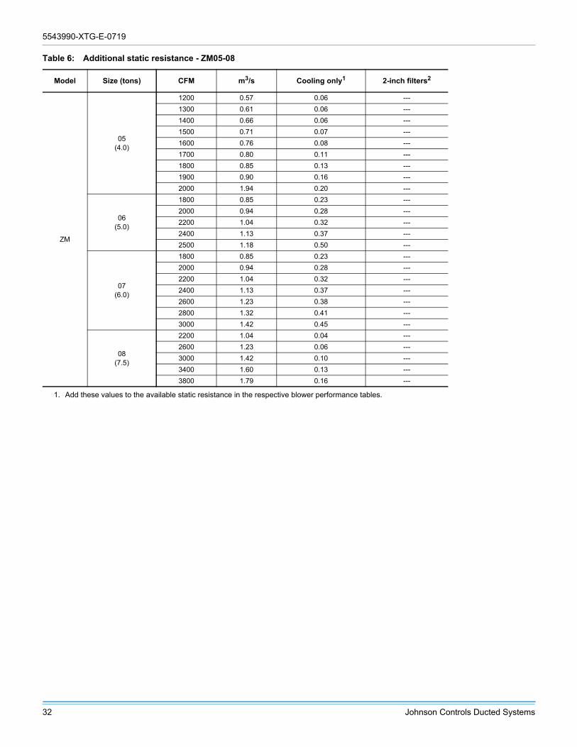
Table 6: Additional static resistance - ZM05-08
Model Size (tons) CFM m3/s Cooling only1 2-inch filters2
ZM
05(4.0)
1200 0.57 0.06 ---
1300 0.61 0.06 ---
1400 0.66 0.06 ---
1500 0.71 0.07 ---
1600 0.76 0.08 ---
1700 0.80 0.11 ---
1800 0.85 0.13 ---
1900 0.90 0.16 ---
2000 1.94 0.20 ---
06(5.0)
1800 0.85 0.23 ---
2000 0.94 0.28 ---
2200 1.04 0.32 ---
2400 1.13 0.37 ---
2500 1.18 0.50 ---
07(6.0)
1800 0.85 0.23 ---
2000 0.94 0.28 ---
2200 1.04 0.32 ---
2400 1.13 0.37 ---
2600 1.23 0.38 ---
2800 1.32 0.41 ---
3000 1.42 0.45 ---
08(7.5)
2200 1.04 0.04 ---
2600 1.23 0.06 ---
3000 1.42 0.10 ---
3400 1.60 0.13 ---
3800 1.79 0.16 ---
1. Add these values to the available static resistance in the respective blower performance tables.
5543990-XTG-E-0719
Johnson Controls Ducted Systems 33
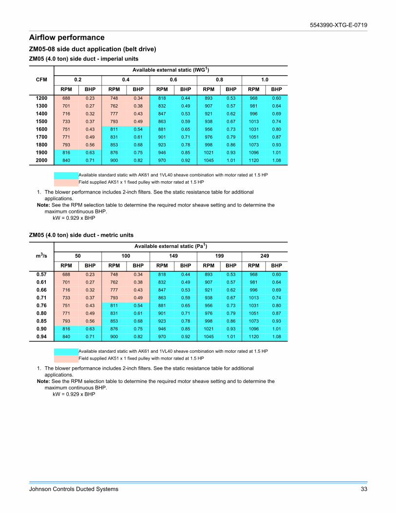
Airflow performance
ZM05-08 side duct application (belt drive)
ZM05 (4.0 ton) side duct - imperial units
CFM
Available external static (IWG1)
0.2 0.4 0.6 0.8 1.0
RPM BHP RPM BHP RPM BHP RPM BHP RPM BHP
1200 688 0.23 748 0.34 818 0.44 893 0.53 968 0.60
1300 701 0.27 762 0.38 832 0.49 907 0.57 981 0.64
1400 716 0.32 777 0.43 847 0.53 921 0.62 996 0.69
1500 733 0.37 793 0.49 863 0.59 938 0.67 1013 0.74
1600 751 0.43 811 0.54 881 0.65 956 0.73 1031 0.80
1700 771 0.49 831 0.61 901 0.71 976 0.79 1051 0.87
1800 793 0.56 853 0.68 923 0.78 998 0.86 1073 0.93
1900 816 0.63 876 0.75 946 0.85 1021 0.93 1096 1.01
2000 840 0.71 900 0.82 970 0.92 1045 1.01 1120 1.08
Available standard static with AK61 and 1VL40 sheave combination with motor rated at 1.5 HP
Field supplied AK51 x 1 fixed pulley with motor rated at 1.5 HP
1. The blower performance includes 2-inch filters. See the static resistance table for additional applications.
Note: See the RPM selection table to determine the required motor sheave setting and to determine the maximum continuous BHP.
kW = 0.929 x BHP
ZM05 (4.0 ton) side duct - metric units
m3/s
Available external static (Pa1)
50 100 149 199 249
RPM BHP RPM BHP RPM BHP RPM BHP RPM BHP
0.57 688 0.23 748 0.34 818 0.44 893 0.53 968 0.60
0.61 701 0.27 762 0.38 832 0.49 907 0.57 981 0.64
0.66 716 0.32 777 0.43 847 0.53 921 0.62 996 0.69
0.71 733 0.37 793 0.49 863 0.59 938 0.67 1013 0.74
0.76 751 0.43 811 0.54 881 0.65 956 0.73 1031 0.80
0.80 771 0.49 831 0.61 901 0.71 976 0.79 1051 0.87
0.85 793 0.56 853 0.68 923 0.78 998 0.86 1073 0.93
0.90 816 0.63 876 0.75 946 0.85 1021 0.93 1096 1.01
0.94 840 0.71 900 0.82 970 0.92 1045 1.01 1120 1.08
Available standard static with AK61 and 1VL40 sheave combination with motor rated at 1.5 HP
Field supplied AK51 x 1 fixed pulley with motor rated at 1.5 HP
1. The blower performance includes 2-inch filters. See the static resistance table for additional applications.
Note: See the RPM selection table to determine the required motor sheave setting and to determine the maximum continuous BHP.
kW = 0.929 x BHP

5543990-XTG-E-0719
34 Johnson Controls Ducted Systems
ZM06 (5.0 ton) side duct - imperial units
CFM
Available external static (IWG1)
1. The blower performance includes 2-inch filters. See the static resistance table for additional applications.Note: See the RPM selection table to determine the required motor sheave setting and to determine the
maximum continuous BHP. kW = 0.929 x BHP
0.2 0.4 0.6 0.8 1.0
RPM BHP RPM BHP RPM BHP RPM BHP RPM BHP
1500 485 0.30 553 0.43 627 0.55 698 0.65 761 0.73
1600 495 0.33 564 0.47 637 0.59 709 0.69 772 0.77
1700 506 0.37 575 0.51 648 0.62 720 0.72 782 0.80
1800 518 0.41 586 0.55 659 0.66 731 0.76 794 0.84
1900 530 0.45 598 0.59 671 0.70 743 0.80 806 0.89
2000 542 0.49 610 0.63 684 0.75 755 0.85 818 0.93
2100 555 0.54 623 0.68 696 0.79 768 0.89 831 0.98
2200 568 0.59 636 0.72 710 0.84 781 0.94 844 1.02
2300 582 0.64 650 0.77 724 0.89 795 0.99 858 1.07
2400 596 0.69 664 0.83 738 0.94 809 1.04 872 1.12
2500 611 0.74 679 0.88 752 1.00 824 1.10 887 1.18
Available standard static with AK74 and 1VL40 sheave combination with motor rated at 1.5 HP
Field supplied AK66 x 1 fixed pulley with motor rated at 1.5 HP
ZM06 (5.0 ton) side duct - metric units
m3/s
Available external static (Pa1)
1. The blower performance includes 2-inch filters. See the static resistance table for additional applications.Note: See the RPM selection table to determine the required motor sheave setting and to determine the
maximum continuous BHP. kW = 0.929 x BHP
50 100 149 199 249
RPM BHP RPM BHP RPM BHP RPM BHP RPM BHP
0.71 485 0.30 553 0.43 627 0.55 698 0.65 761 0.73
0.76 495 0.33 564 0.47 637 0.59 709 0.69 772 0.77
0.80 506 0.37 575 0.51 648 0.62 720 0.72 782 0.80
0.85 518 0.41 586 0.55 659 0.66 731 0.76 794 0.84
0.90 530 0.45 598 0.59 671 0.70 743 0.80 806 0.89
0.94 542 0.49 610 0.63 684 0.75 755 0.85 818 0.93
0.99 555 0.54 623 0.68 696 0.79 768 0.89 831 0.98
1.04 568 0.59 636 0.72 710 0.84 781 0.94 844 1.02
1.09 582 0.64 650 0.77 724 0.89 795 0.99 858 1.07
1.13 596 0.69 664 0.83 738 0.94 809 1.04 872 1.12
1.18 611 0.74 679 0.88 752 1.00 824 1.10 887 1.18
Available standard static with AK74 and 1VL40 sheave combination with motor rated at 1.5 HP
Field supplied AK66 x 1 fixed pulley with motor rated at 1.5 HP

5543990-XTG-E-0719
Johnson Controls Ducted Systems 35
ZM07 (6.0 ton) side duct - imperial units
CFM
Available external static (IWG1)
1. The blower performance includes 2-inch filters. See the static resistance table for additional applications.Note: See the RPM selection table to determine the required motor sheave setting and to determine the
maximum continuous BHP. kW = 0.929 x BHP
0.2 0.4 0.6 0.8 1.0
RPM BHP RPM BHP RPM BHP RPM BHP RPM BHP
1800 437 0.49 518 0.62 601 0.72 675 0.79 730 0.82
1900 445 0.52 527 0.66 610 0.76 684 0.82 739 0.85
2000 454 0.55 536 0.69 619 0.79 693 0.85 748 0.89
2100 464 0.59 546 0.73 628 0.83 702 0.89 758 0.92
2200 474 0.63 555 0.77 638 0.86 712 0.93 768 0.96
2300 484 0.66 565 0.80 648 0.90 722 0.97 778 1.00
2400 494 0.70 576 0.84 659 0.94 733 1.01 788 1.04
2500 505 0.75 587 0.89 669 0.98 743 1.05 799 1.08
2600 516 0.79 598 0.93 680 1.03 754 1.09 810 1.12
2700 528 0.83 609 0.97 692 1.07 766 1.13 821 1.17
2800 539 0.88 621 1.02 704 1.12 778 1.18 833 1.21
2900 551 0.92 633 1.06 715 1.16 789 1.23 845 1.26
3000 563 0.97 645 1.11 728 1.21 802 1.27 857 1.30
Available standard static with AK74 and 1VP34 sheave combination with motor rated at 2 HP
Field supplied AK79 x 1 fixed pulley with motor rated at 2 HP
ZM07 (6.0 ton) side duct - metric units
m3/s
Available external static (Pa1)
1. The blower performance includes 2-inch filters. See the static resistance table for additional applications.Note: See the RPM selection table to determine the required motor sheave setting and to determine the
maximum continuous BHP. kW = 0.929 x BHP
50 100 149 199 249
RPM BHP RPM BHP RPM BHP RPM BHP RPM BHP
0.85 437 0.49 518 0.62 601 0.72 675 0.79 730 0.82
0.90 445 0.52 527 0.66 610 0.76 684 0.82 739 0.85
0.94 454 0.55 536 0.69 619 0.79 693 0.85 748 0.89
0.99 464 0.59 546 0.73 628 0.83 702 0.89 758 0.92
1.04 474 0.63 555 0.77 638 0.86 712 0.93 768 0.96
1.09 484 0.66 565 0.80 648 0.90 722 0.97 778 1.00
1.13 494 0.70 576 0.84 659 0.94 733 1.01 788 1.04
1.18 505 0.75 587 0.89 669 0.98 743 1.05 799 1.08
1.23 516 0.79 598 0.93 680 1.03 754 1.09 810 1.12
1.28 528 0.83 609 0.97 692 1.07 766 1.13 821 1.17
1.33 539 0.88 621 1.02 704 1.12 778 1.18 833 1.21
1.37 551 0.92 633 1.06 715 1.16 789 1.23 845 1.26
1.42 563 0.97 645 1.11 728 1.21 802 1.27 857 1.30
Available standard static with AK74 and 1VP34 sheave combination with motor rated at 2 HP
Field supplied AK79 x 1 fixed pulley with motor rated at 2 HP

5543990-XTG-E-0719
36 Johnson Controls Ducted Systems
ZM08 (7.5 ton) side duct - imperial units
CFM
Available external static (IWG1)
1. The blower performance includes 2-inch filters. See the static resistance table for additional applications.Note: See the RPM selection table to determine the required motor sheave setting and to determine the
maximum continuous BHP. kW = 0.929 x BHP
0.2 0.4 0.6 0.8 1.0
RPM BHP RPM BHP RPM BHP RPM BHP RPM BHP
2200 488 0.55 562 0.71 645 0.84 722 0.93 780 0.98
2400 508 0.64 583 0.80 666 0.93 743 1.02 801 1.07
2600 530 0.74 605 0.90 687 1.03 765 1.12 823 1.17
2800 553 0.85 628 1.00 711 1.14 788 1.23 846 1.27
3000 578 0.96 653 1.12 735 1.25 813 1.34 870 1.39
3200 604 1.08 679 1.24 761 1.37 838 1.46 896 1.51
3400 631 1.20 706 1.36 788 1.49 865 1.59 923 1.63
3600 659 1.33 734 1.49 816 1.62 894 1.72 952 1.76
3800 688 1.47 763 1.63 846 1.76 923 1.85 981 1.90
Available standard static with AK89 and 1VL44 sheave combination with motor rated at 2 HP
Field supplied AK94 x 1 fixed pulley with motor rated at 2 HP
ZM08 (7.5 ton) side duct - metric units
m3/s
Available external static (Pa1)
1. The blower performance includes 2-inch filters. See the static resistance table for additional applications.Note: See the RPM selection table to determine the required motor sheave setting and to determine the
maximum continuous BHP. kW = 0.929 x BHP
50 100 149 199 249
RPM BHP RPM BHP RPM BHP RPM BHP RPM BHP
1.04 488 0.55 562 0.71 645 0.84 722 0.93 780 0.98
1.13 508 0.64 583 0.80 666 0.93 743 1.02 801 1.07
1.23 530 0.74 605 0.90 687 1.03 765 1.12 823 1.17
1.32 553 0.85 628 1.00 711 1.14 788 1.23 846 1.27
1.42 578 0.96 653 1.12 735 1.25 813 1.34 870 1.39
1.51 604 1.08 679 1.24 761 1.37 838 1.46 896 1.51
1.60 631 1.20 706 1.36 788 1.49 865 1.59 923 1.63
1.70 659 1.33 734 1.49 816 1.62 894 1.72 952 1.76
1.79 688 1.47 763 1.63 846 1.76 923 1.85 981 1.90
Available standard static with AK89 and 1VL44 sheave combination with motor rated at 2 HP
Field supplied AK94 x 1 fixed pulley with motor rated at 2 HP

5543990-XTG-E-0719
Johnson Controls Ducted Systems 37
Table 7: ZM05-08 bottom duct application (belt drive)
ZM05 (4.0 ton) bottom duct - imperial units
CFM
Available external static (IWG1)
0.2 0.4 0.6 0.8 1.0
RPM BHP RPM BHP RPM BHP RPM BHP RPM BHP
1200 688 0.30 750 0.39 822 0.47 898 0.56 975 0.51
1300 702 0.35 765 0.43 838 0.52 915 0.60 990 0.67
1400 720 0.39 783 0.48 854 0.57 930 0.66 1008 0.73
1500 739 0.44 801 0.54 873 0.63 950 0.71 1027 0.78
1600 759 0.51 821 0.60 893 0.69 970 0.69 1046 0.83
1700 780 0.57 843 0.66 915 0.75 991 0.82 1068 0.90
1800 803 0.63 865 0.72 937 0.82 1014 0.90 1091 0.96
1900 827 0.69 889 0.79 960 0.87 1037 0.95 1114 1.04
2000 850 0.76 913 0.85 984 0.94 1061 1.02 1138 1.10
Available standard static with AK61 and 1VL40 sheave combination with motor rated at 1.5 HP
Field supplied AK51 x 1 fixed pulley with motor rated at 1.5 HP
1. The blower performance includes 2-inch filters. See the static resistance table for additional applications.
Note: See the RPM selection table to determine the required motor sheave setting and to determine the maximum continuous BHP.
kW = 0.929 x BHP
ZM05 (4.0 ton) bottom duct - metric units
m3/s
Available external static (Pa1)
50 100 149 199 249
RPM BHP RPM BHP RPM BHP RPM BHP RPM BHP
0.57 688 0.30 750 0.39 822 0.47 898 0.56 975 0.51
0.61 702 0.35 765 0.43 838 0.52 915 0.60 990 0.67
0.66 720 0.39 783 0.48 854 0.57 930 0.66 1008 0.73
0.71 739 0.44 801 0.54 873 0.63 950 0.71 1027 0.78
0.76 759 0.51 821 0.60 893 0.69 970 0.69 1046 0.83
0.80 780 0.57 843 0.66 915 0.75 991 0.82 1068 0.90
0.85 803 0.63 865 0.72 937 0.82 1014 0.90 1091 0.96
0.90 827 0.69 889 0.79 960 0.87 1037 0.95 1114 1.04
0.94 850 0.76 913 0.85 984 0.94 1061 1.02 1138 1.10
Available standard static with AK61 and 1VL40 sheave combination with motor rated at 1.5 HP
Field supplied AK51 x 1 fixed pulley with motor rated at 1.5 HP
1. The blower performance includes 2-inch filters. See the static resistance table for additional applications.
Note: See the RPM selection table to determine the required motor sheave setting and to determine the maximum continuous BHP.
kW = 0.929 x BHP

5543990-XTG-E-0719
38 Johnson Controls Ducted Systems
ZM06 (5.0 ton) bottom duct - imperial units
CFM
Available external static (IWG1)
1. The blower performance includes 2-inch filters. See the static resistance table for additional applications.Note: See the RPM selection table to determine the required motor sheave setting and to determine the
maximum continuous BHP. kW = 0.929 x BHP
0.2 0.4 0.6 0.8 1.0
RPM BHP RPM BHP RPM BHP RPM BHP RPM BHP
1500 515 0.29 580 0.41 650 0.52 717 0.62 778 0.69
1600 530 0.30 595 0.44 665 0.54 733 0.64 793 0.71
1700 544 0.34 609 0.46 679 0.57 747 0.66 806 0.74
1800 558 0.37 621 0.50 691 0.60 760 0.69 820 0.77
1900 570 0.41 635 0.54 704 0.65 772 0.64 832 0.82
2000 582 0.46 647 0.59 717 0.69 785 0.79 845 0.86
2100 595 0.52 660 0.64 729 0.75 798 0.84 858 0.93
2200 608 0.58 673 0.69 743 0.80 811 0.90 871 0.97
2300 623 0.64 687 0.75 753 0.87 826 0.96 886 1.04
2400 639 0.69 702 0.83 773 0.92 841 1.02 901 1.09
2500 655 0.75 719 0.89 789 0.99 857 1.09 917 1.16
Available standard static with AK74 and 1VL40 sheave combination with motor rated at 1.5 HP
Field supplied AK66 x 1 fixed pulley with motor rated at 1.5 HP
ZM06 (5.0 ton) bottom duct - metric units
m3/s
Available external static (Pa1)
1. The blower performance includes 2-inch filters. See the static resistance table for additional applications.Note: See the RPM selection table to determine the required motor sheave setting and to determine the
maximum continuous BHP. kW = 0.929 x BHP
50 100 149 199 249
RPM BHP RPM BHP RPM BHP RPM BHP RPM BHP
0.71 515 0.29 580 0.41 650 0.52 717 0.62 778 0.69
0.76 530 0.30 595 0.44 665 0.54 733 0.64 793 0.71
0.80 544 0.34 609 0.46 679 0.57 747 0.66 806 0.74
0.85 558 0.37 621 0.50 691 0.60 760 0.69 820 0.77
0.90 570 0.41 635 0.54 704 0.65 772 0.64 832 0.82
0.94 582 0.46 647 0.59 717 0.69 785 0.79 845 0.86
0.99 595 0.52 660 0.64 729 0.75 798 0.84 858 0.93
1.04 608 0.58 673 0.69 743 0.80 811 0.90 871 0.97
1.09 623 0.64 687 0.75 753 0.87 826 0.96 886 1.04
1.13 639 0.69 702 0.83 773 0.92 841 1.02 901 1.09
1.18 655 0.75 719 0.89 789 0.99 857 1.09 917 1.16
Available standard static with AK74 and 1VL40 sheave combination with motor rated at 1.5 HP
Field supplied AK66 x 1 fixed pulley with motor rated at 1.5 HP

5543990-XTG-E-0719
Johnson Controls Ducted Systems 39
ZM07 (6.0 ton) bottom duct - imperial units
CFM
Available external static (IWG1)
1. The blower performance includes 2-inch filters. See the static resistance table for additional applications.Note: See the RPM selection table to determine the required motor sheave setting and to determine the
maximum continuous BHP. kW = 0.929 x BHP
0.2 0.4 0.6 0.8 1.0
RPM BHP RPM BHP RPM BHP RPM BHP RPM BHP
1800 441 0.53 525 0.66 610 0.74 685 0.80 741 0.81
1900 450 0.57 535 0.70 620 0.80 695 0.84 751 0.85
2000 460 0.60 545 0.74 630 0.83 705 0.88 761 0.90
2100 471 0.64 556 0.79 639 0.88 715 0.93 772 0.93
2200 482 0.69 565 0.83 651 0.91 726 0.97 783 0.98
2300 493 0.73 577 0.87 662 0.96 737 1.01 794 1.03
2400 505 0.77 589 0.91 674 1.00 749 1.06 806 1.07
2500 518 0.83 602 0.97 686 1.05 761 1.10 819 1.11
2600 530 0.87 615 1.02 698 1.11 774 1.15 831 1.16
2700 545 0.91 628 1.06 713 1.15 788 1.19 844 1.21
2800 558 0.97 642 1.11 727 1.20 802 1.24 858 1.26
2900 572 1.01 656 1.15 741 1.24 816 1.29 873 1.31
3000 587 1.06 671 1.20 757 1.29 831 1.34 887 1.35
Available standard static with AK74 and 1VP34 sheave combination with motor rated at 2 HP
Field supplied AK79 x 1 fixed pulley with motor rated at 2 HP
ZM07 (6.0 ton) bottom duct - metric units
m3/s
Available external static (Pa1)
1. The blower performance includes 2-inch filters. See the static resistance table for additional applications.Note: See the RPM selection table to determine the required motor sheave setting and to determine the
maximum continuous BHP. kW = 0.929 x BHP
50 100 149 199 249
RPM BHP RPM BHP RPM BHP RPM BHP RPM BHP
0.85 441 0.53 525 0.66 610 0.74 685 0.80 741 0.81
0.90 450 0.57 535 0.70 620 0.80 695 0.84 751 0.85
0.94 460 0.60 545 0.74 630 0.83 705 0.88 761 0.90
0.99 471 0.64 556 0.79 639 0.88 715 0.93 772 0.93
1.04 482 0.69 565 0.83 651 0.91 726 0.97 783 0.98
1.09 493 0.73 577 0.87 662 0.96 737 1.01 794 1.03
1.13 505 0.77 589 0.91 674 1.00 749 1.06 806 1.07
1.18 518 0.83 602 0.97 686 1.05 761 1.10 819 1.11
1.23 530 0.87 615 1.02 698 1.11 774 1.15 831 1.16
1.28 545 0.91 628 1.06 713 1.15 788 1.19 844 1.21
1.33 558 0.97 642 1.11 727 1.20 802 1.24 858 1.26
1.37 572 1.01 656 1.15 741 1.24 816 1.29 873 1.31
1.42 587 1.06 671 1.20 757 1.29 831 1.34 887 1.35
Available standard static with AK74 and 1VP34 sheave combination with motor rated at 2 HP
Field supplied AK79 x 1 fixed pulley with motor rated at 2 HP

5543990-XTG-E-0719
40 Johnson Controls Ducted Systems
ZM08 (7.5 ton) bottom duct - imperial units
CFM
Available external static (IWG1)
1. The blower performance includes 2-inch filters. See the static resistance table for additional applications.Note: See the RPM selection table to determine the required motor sheave setting and to determine the
maximum continuous BHP. kW = 0.929 x BHP
0.2 0.4 0.6 0.8 1.0
RPM BHP RPM BHP RPM BHP RPM BHP RPM BHP
2200 497 0.61 573 0.76 658 0.86 737 0.92 795 0.95
2400 519 0.70 596 0.84 681 0.94 760 0.92 818 1.03
2600 542 0.79 620 0.94 703 1.04 782 1.11 842 1.13
2800 567 0.91 644 1.04 729 1.15 806 1.22 866 1.23
3000 592 1.01 669 1.16 753 1.26 832 1.33 890 1.35
3200 619 1.13 696 1.26 780 1.37 857 1.44 917 1.46
3400 645 1.25 723 1.38 806 1.49 885 1.56 943 1.57
3600 673 1.38 750 1.51 834 1.62 914 1.69 972 1.70
3800 703 1.50 780 1.65 865 1.75 943 1.82 1002 1.84
Available standard static with AK89 and 1VL44 sheave combination with motor rated at 2 HP
Field supplied AK94 x 1 fixed pulley with motor rated at 2 HP
ZM08 (7.5 ton) bottom duct - metric units
m3/s
Available external static (Pa1)
1. The blower performance includes 2-inch filters. See the static resistance table for additional applications.Note: See the RPM selection table to determine the required motor sheave setting and to determine the
maximum continuous BHP. kW = 0.929 x BHP
50 100 149 199 249
RPM BHP RPM BHP RPM BHP RPM BHP RPM BHP
1.04 497 0.61 573 0.76 658 0.86 737 0.92 795 0.95
1.13 519 0.70 596 0.84 681 0.94 760 0.92 818 1.03
1.23 542 0.79 620 0.94 703 1.04 782 1.11 842 1.13
1.32 567 0.91 644 1.04 729 1.15 806 1.22 866 1.23
1.42 592 1.01 669 1.16 753 1.26 832 1.33 890 1.35
1.51 619 1.13 696 1.26 780 1.37 857 1.44 917 1.46
1.60 645 1.25 723 1.38 806 1.49 885 1.56 943 1.57
1.70 673 1.38 750 1.51 834 1.62 914 1.69 972 1.70
1.79 703 1.50 780 1.65 865 1.75 943 1.82 1002 1.84
Available standard static with AK89 and 1VL44 sheave combination with motor rated at 2 HP
Field supplied AK94 x 1 fixed pulley with motor rated at 2 HP
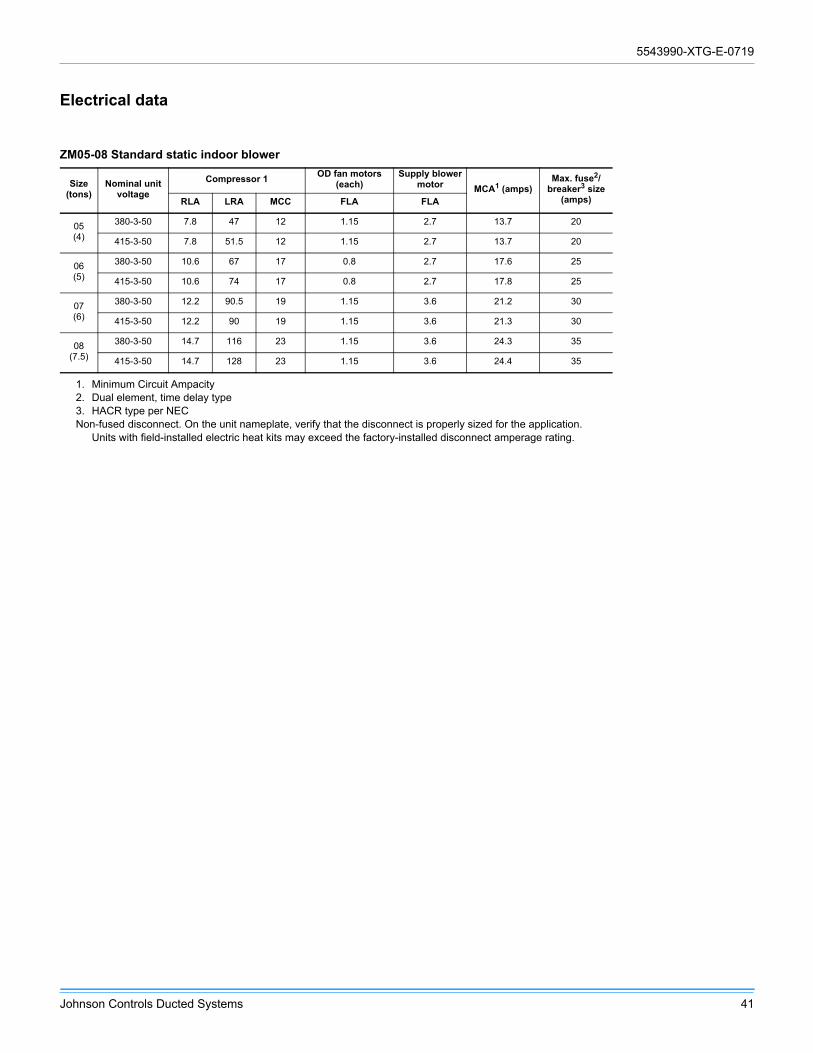
5543990-XTG-E-0719
Johnson Controls Ducted Systems 41
Electrical data
ZM05-08 Standard static indoor blower
Size (tons)
Nominal unit voltage
Compressor 1OD fan motors
(each)Supply blower
motor MCA1 (amps)
1. Minimum Circuit Ampacity
Max. fuse2/breaker3 size
(amps)
2. Dual element, time delay type3. HACR type per NECNon-fused disconnect. On the unit nameplate, verify that the disconnect is properly sized for the application.
Units with field-installed electric heat kits may exceed the factory-installed disconnect amperage rating.
RLA LRA MCC FLA FLA
05(4)
380-3-50 7.8 47 12 1.15 2.7 13.7 20
415-3-50 7.8 51.5 12 1.15 2.7 13.7 20
06(5)
380-3-50 10.6 67 17 0.8 2.7 17.6 25
415-3-50 10.6 74 17 0.8 2.7 17.8 25
07(6)
380-3-50 12.2 90.5 19 1.15 3.6 21.2 30
415-3-50 12.2 90 19 1.15 3.6 21.3 30
08(7.5)
380-3-50 14.7 116 23 1.15 3.6 24.3 35
415-3-50 14.7 128 23 1.15 3.6 24.4 35
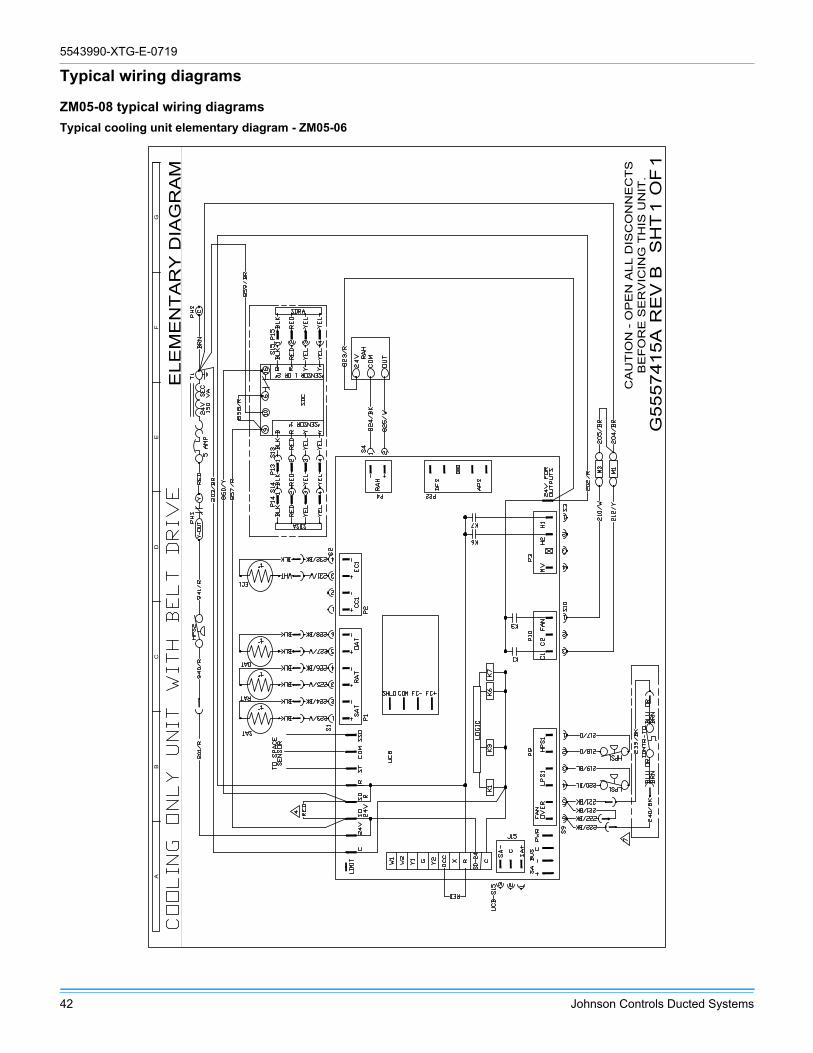
5543990-XTG-E-0719
42 Johnson Controls Ducted Systems
Typical wiring diagrams
ZM05-08 typical wiring diagrams
Typical cooling unit elementary diagram - ZM05-06
AB
CD
EF
G
ELE
ME
NT
AR
Y D
IAG
RA
M
CA
UT
ION
- O
PE
N A
LL D
ISC
ON
NE
CT
SB
EF
OR
E S
ER
VIC
ING
TH
IS U
NIT
.R
EV
OF
SH
TG
5557
415A
B1
1

5543990-XTG-E-0719
Johnson Controls Ducted Systems 43
Typical ZM05 cooling unit belt drive elementary diagram control circuit
AB
CD
EF
G
ELE
ME
NT
AR
Y D
IAG
RA
M
CA
UT
ION
- O
PE
N A
LL D
ISC
ON
NE
CT
SB
EF
OR
E S
ER
VIC
ING
TH
IS U
NIT
.R
EV
OF
SH
TG
5557
416A
B1
1

5543990-XTG-E-0719
44 Johnson Controls Ducted Systems
Typical ZM06 cooling unit belt drive elementary diagram control circuit
AB
CD
EF
G
ELE
ME
NT
AR
Y D
IAG
RA
M
CA
UT
ION
- O
PE
N A
LL D
ISC
ON
NE
CT
SB
EF
OR
E S
ER
VIC
ING
TH
IS U
NIT
.R
EV
OF
SH
TG
5557
417A
B1
1
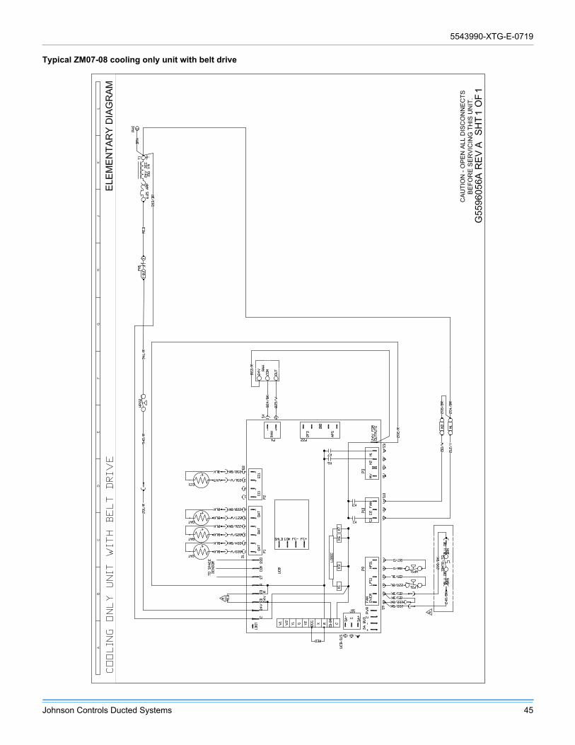
5543990-XTG-E-0719
Johnson Controls Ducted Systems 45
Typical ZM07-08 cooling only unit with belt drive

5543990-XTG-E-0719
46 Johnson Controls Ducted Systems
Typical ZM07-08 cooling only unit 415-3-50 belt drive

5543990-XTG-E-0719
Johnson Controls Ducted Systems 47
Weights and dimensions
ZM05-08 unit weightsUnit 4 point load weight Unit 6 point load weight
Unit center of gravity
Table 8: ZM05-08 corner weights - imperial units
ModelSize
(Tons)Weight (lbs.) Center of gravity 4 point load location (lbs.) 6 point load location (lbs.)
Shipping Operating X Y A B C D A B C D E F
ZM05(4)
630 625 35 25 168 152 145 161 114 106 99 95 102 109
ZM06(5)
840 835 45 35 228 239 188 180 151 156 161 126 123 119
ZM07(6)
925 920 44 35 258 257 202 203 172 171 171 135 135 136
ZM08
(7.5)965 960 45 28 209 223 272 255 138 144 150 183 176 168
Table 9: ZM05-08 corner weights - metric units
ModelSize(kW)
Weight (kg) Center of gravity (mm) 4 point load location (kg) 6 point load location (kg)Shipping Operating X Y A B C D A B C D E F
ZM05
(14)286 283 892 635 76 69 66 73 52 48 45 43 46 49
ZM06
(18)381 379 1133 876 103 108 85 82 68 71 73 57 56 54
ZM07
(21)420 417 1105 876 117 116 92 92 78 78 78 61 61 62
ZM08
(26)438 435 1143 706 95 101 123 116 63 65 68 83 80 76
LEFTFRONT
YX

5543990-XTG-E-0719
48 Johnson Controls Ducted Systems
ZM05-08 unit accessory weights
Unit accessory Weights (lbs.) Weights (kg)
Curb rigid 14-in. (356 mm) small footprint 145 66
Curb rigid 14-in. (356 mm) large footprint 135 61
Curb rigid 24-in. (610 mm) small footprint 135 61
Curb rigid 24-in. (610 mm) large footprint 135 61
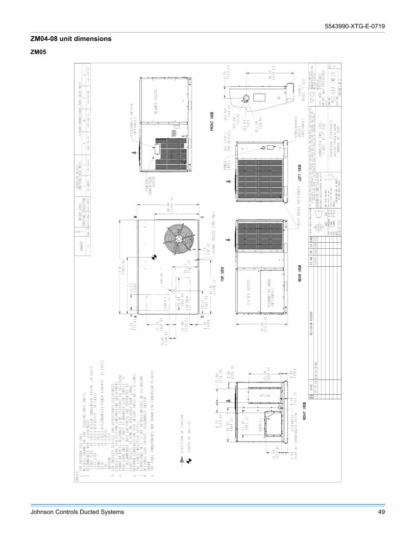
5543990-XTG-E-0719
Johnson Controls Ducted Systems 49
ZM04-08 unit dimensions
ZM05
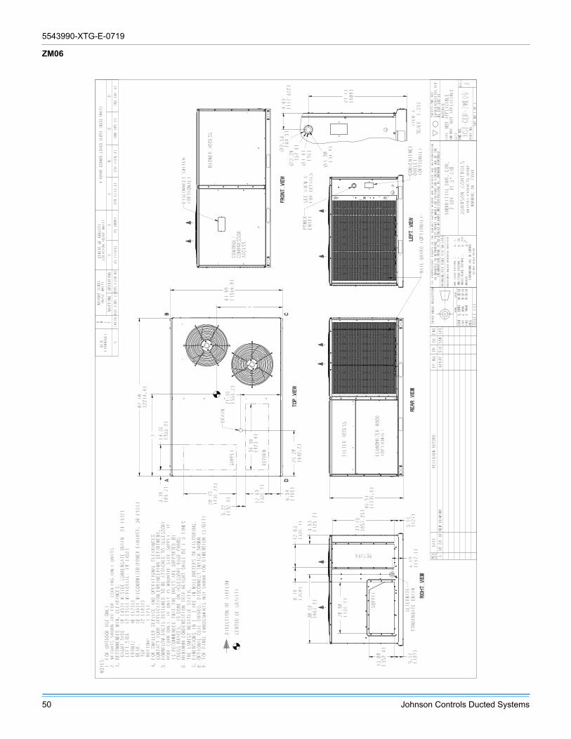
5543990-XTG-E-0719
50 Johnson Controls Ducted Systems
ZM06

5543990-XTG-E-0719
Johnson Controls Ducted Systems 51
ZM07 and ZM08
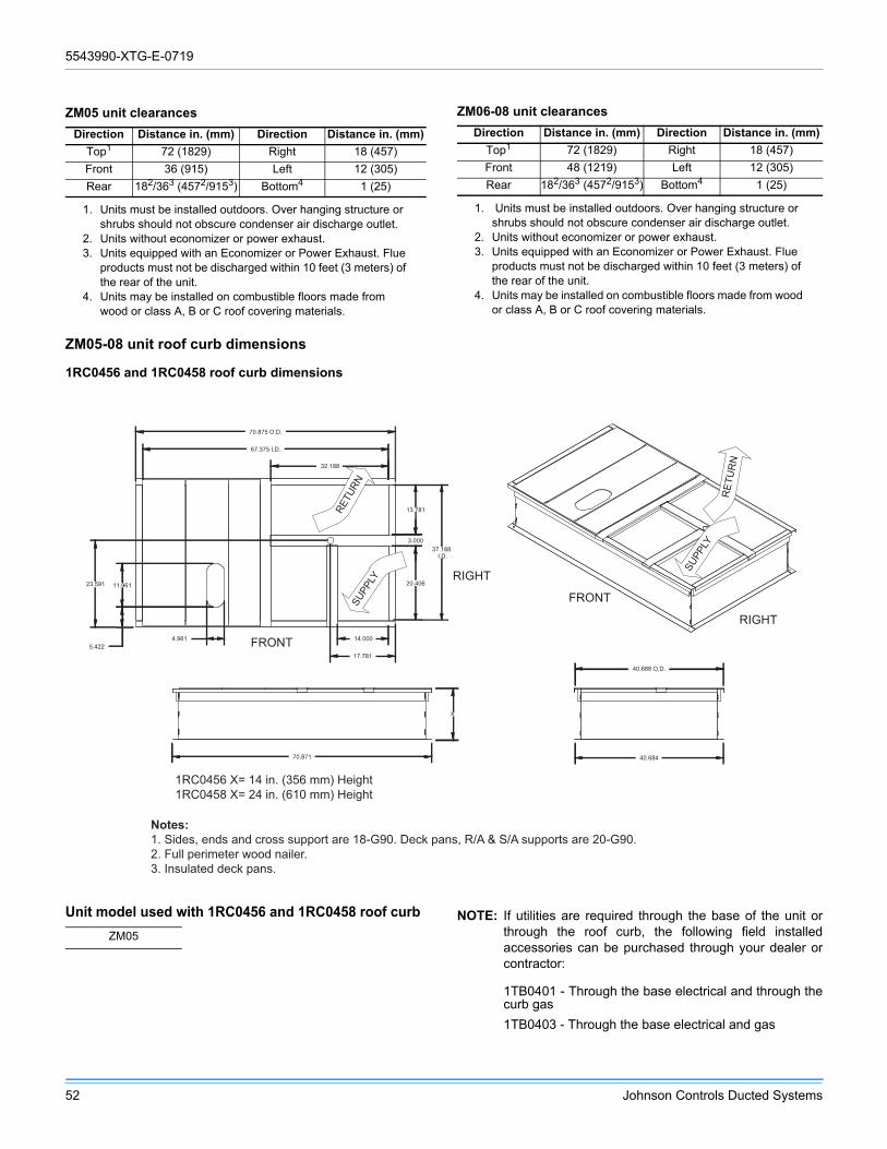
5543990-XTG-E-0719
52 Johnson Controls Ducted Systems
ZM05-08 unit roof curb dimensions
1RC0456 and 1RC0458 roof curb dimensions
NOTE: If utilities are required through the base of the unit orthrough the roof curb, the following field installedaccessories can be purchased through your dealer orcontractor:
1TB0401 - Through the base electrical and through thecurb gas
1TB0403 - Through the base electrical and gas
ZM05 unit clearances
Direction Distance in. (mm) Direction Distance in. (mm)
Top1
1. Units must be installed outdoors. Over hanging structure or shrubs should not obscure condenser air discharge outlet.
72 (1829) Right 18 (457)
Front 36 (915) Left 12 (305)
Rear 182/363 (4572/9153)
2. Units without economizer or power exhaust.3. Units equipped with an Economizer or Power Exhaust. Flue
products must not be discharged within 10 feet (3 meters) of the rear of the unit.
Bottom4
4. Units may be installed on combustible floors made from wood or class A, B or C roof covering materials.
1 (25)
ZM06-08 unit clearances
Direction Distance in. (mm) Direction Distance in. (mm)
Top1
1. Units must be installed outdoors. Over hanging structure or shrubs should not obscure condenser air discharge outlet.
72 (1829) Right 18 (457)
Front 48 (1219) Left 12 (305)
Rear 182/363 (4572/9153)
2. Units without economizer or power exhaust.3. Units equipped with an Economizer or Power Exhaust. Flue
products must not be discharged within 10 feet (3 meters) of the rear of the unit.
Bottom4
4. Units may be installed on combustible floors made from wood or class A, B or C roof covering materials.
1 (25)
O.D.40.688
40.684
X
70.871
4.961
I.D.
37.188
5.422
67.375
I.D.
32.188
13.781
3.000
20.406
17.781
14.000
23.591 11.961
70.875 O.D.
RET
UR
N
SUPP
LY
RETU
RNSU
PPLY
1RC0456 X= 14 in. (356 mm) Height1RC0458 X= 24 in. (610 mm) Height
Notes:1. Sides, ends and cross support are 18-G90. Deck pans, R/A & S/A supports are 20-G90.2. Full perimeter wood nailer.3. Insulated deck pans.
FRONT
FRONT
RIGHT
RIGHT
Unit model used with 1RC0456 and 1RC0458 roof curb
ZM05
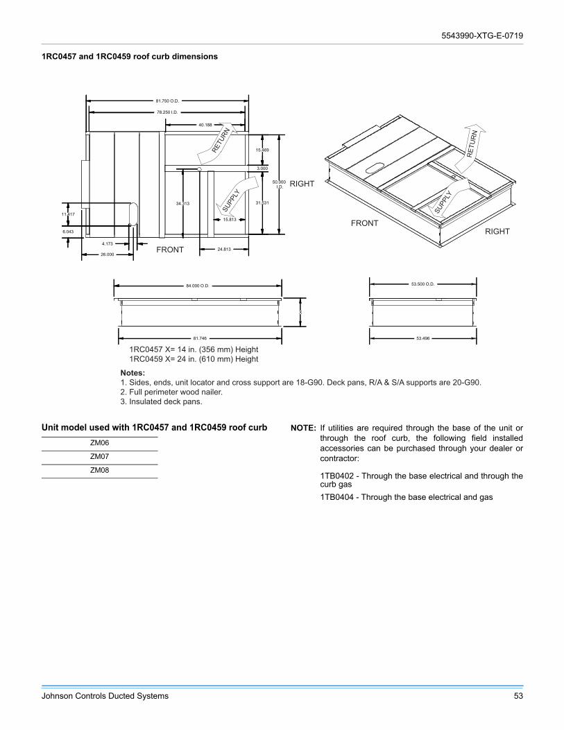
5543990-XTG-E-0719
Johnson Controls Ducted Systems 53
1RC0457 and 1RC0459 roof curb dimensions
NOTE: If utilities are required through the base of the unit orthrough the roof curb, the following field installedaccessories can be purchased through your dealer orcontractor:
1TB0402 - Through the base electrical and through thecurb gas
1TB0404 - Through the base electrical and gas
26.000
X
81.746
84.000 O.D. O.D.53.500
53.496
11.417
6.043
24.8134.173
34.313
I.D.
50.000
78.250
I.D.
40.188
15.469
3.000
15.813
31.531
81.750 O.D.
RET
UR
N
SUPP
LY
RETU
RNSU
PPLY
FRONT
RIGHT
FRONTRIGHT
1RC0457 X= 14 in. (356 mm) Height1RC0459 X= 24 in. (610 mm) Height
Notes:1. Sides, ends, unit locator and cross support are 18-G90. Deck pans, R/A & S/A supports are 20-G90.2. Full perimeter wood nailer.3. Insulated deck pans.
Unit model used with 1RC0457 and 1RC0459 roof curb
ZM06
ZM07
ZM08

5543990-XTG-E-0719
54 Johnson Controls Ducted Systems
Guide specifications
YORK® GUIDE MECHANICAL SPECIFICATIONSSINGLE PACKAGE AIR CONDITIONERS
4 THROUGH 7.5 NOMINAL TONS
Sun™ Core SERIES
Size Range:4 to 7.5 Tons Nominal Cooling
48,000 to 90,000 BTUH Nominal
Model Series: ZM
DIVISION 23 – HEATING, VENTILATING, AND AIR-CONDITIONING (HVAC)
Number Title
23 00 00 HEATING, VENTILATING, AND AIR-CONDITIONING (HVAC)
23 06 00 Schedules for HVAC23 06 80 Schedules for Decentralized HVAC Equipment
23 06 80.13 Decentralized Unitary HVAC Equipment Schedule
23 06 80.13.A. Rooftop unit schedule
23 07 00 HVAC Insulation
23 07 16 HVAC Equipment Insulation
23 07 16.13 Decentralized, Rooftop Units:
23 07 16.13.A. Evaporator fan compartment:
1. Interior cabinet surfaces shall be insulated with a minimum 1/2 in. (12.7 mm) thick, minimum 1 1/2 lb (0.68 kg) density, flexible fiberglass insulation coated on the air side.
2. Insulation and adhesive shall meet NFPA 90A requirements for flame spread and smoke generation.
23 09 00 Instrumentation and Control for HVAC
23 09 13 Instrumentation and Control Devices for HVAC
23 09 13.23 Sensors and Transmitters
23 09 13.23.A. Thermostats
1. Thermostat must
a. energize “G” when calling for fan only or continuous fan.
b. have capability to energize 2 different stages of cooling, and 2 different stages of heating.
c. include capability for occupancy scheduling.
5543990-XTG-E-0719
Johnson Controls Ducted Systems 55
23 09 23 Direct- digital Control system for HVAC
23 09 23.13 Decentralized, Rooftop Units:
23 09 23.13.A. Smart Equipment™ (Unit based microprocessor control)
1. Shall be ASHRAE 62 compliant.
2. Shall include an integrated economizer controller to support an economizer with 2 to 10 v DC actuator input.
3. Controller shall accept the following inputs: space temperature, setpoint adjustment, outdoor air temperature, indoor air quality, outdoor air quality, indoor relative humidity, compressor lockout, fire shutdown, enthalpy, fan status, remote time clock/door switch.
4. Shall accept a CO2 sensor in the conditioned space, and be Demand Control Ventilation ready.
5. Unit shall provide surge protection for the controller through a circuit breaker.
6. Shall have an LED display independently showing the status of activity on the communication bus, and processor operation.
7. Software upgrades will be accomplished by local download. Software upgrades through chip replacements are not allowed.
A. Unit shall be complete with self-contained low-voltage control circuit protected by a resettable circuit breaker on the 24-volt transformer side.
B. Unit shall incorporate a lockout circuit which provides reset capability at the space thermostat or base unit should any of the following standard safety devices trip and shut off compressor:
C. Loss-of-charge/Low-pressure switch.
D. High-pressure switch.
E. Freeze-protection temperature sensor, evaporator coil. If any of the above safety devices trip, an LED (light-emitting diode) indicator shall flash a diagnostic code that indicates which safety switch has tripped.
F. Unit shall incorporate “AUTO RESET” compressor over temperature, over current protection.
G. Unit shall operate with conventional thermostat designs and have a low voltage terminal strip for easy hook-up.
H. Unit control board shall have on-board diagnostics and fault code display.
I. Standard controls shall include anti-short cycle and low voltage protection, and permit cooling operation down to 0ºF (-18ºC).
J. Control board shall monitor each refrigerant safety switch independently.
K. Control board shall retain last 5 fault codes in non-volatile memory, which will not be lost in the event of a power loss.
23 09 23.13.B. RTU Open - multi- protocol, direct digital controller:
1. Shall be ASHRAE 62 compliant.
2. Shall include built- in protocol for BACNET , Modbus , and Johnson N2.
3. Shall allow access of up to 62 network variables (SNVT). Shall be compatible with all open controllers
4. Baud rate Controller shall be selectable using a dip switch.
5. Shall have an LED display independently showing the status of serial communication, running, errors, power, all digital outputs, and all analog inputs.
6. Shall accept the following inputs: space temperature, setpoint adjustment, outdoor air temperature, indoor air quality, outdoor air quality, compressor lock- out, fire shutdown, enthalpy switch, and fan status/filter status/ humidity/ remote occupancy.
7. Software upgrades will be accomplished by either local or remote download. No software upgrades through chip replacements are allowed.
48
HC

5543990-XTG-E-0719
56 Johnson Controls Ducted Systems
23 09 33 Electric and Electronic Control System for HVAC
23 09 33.13 Decentralized, Rooftop Units:
23 09 33.13.A. General:
1. Shall be complete with self- contained low- voltage control circuit protected by a resettable circuit breaker on the 24- v transformer side. Transformer shall have 75VA capability.
2. Shall utilize color- coded wiring.
3. Shall include a central control terminal board to conveniently and safely provide connection points for vital control functions such as: smoke detectors, phase monitor, gas controller, economizer, thermostat, DDC control options, and low and high pressure switches.
4. The heat exchanger shall be controlled by an integrated gas controller (IGC) microprocessor. See heat exchanger section of this specification.
23 09 33.23.B. Safeties:
1. Compressor over- temperature, over- current. High internal pressure differential.
2. Low- pressure switch.
a. Units with 2 compressors shall have different sized connectors for the circuit 1 and circuit 2 low and high pressure switches. They shall physically prevent the cross- wiring of the safety switches between circuits 1 and 2.
b. Low pressure switch shall use different color wire than the high pressure switch. The purpose is to assist the installer and service technician to correctly wire and or troubleshoot the rooftop unit.
3. High- pressure switch.
a. Units with 2 compressors shall have different sized connectors for the circuit 1 and circuit 2 low and high pressure switches. They shall physically prevent the cross- wiring of the safety switches between circuits 1 and 2.
b. High pressure switch shall use different color wire than the low pressure switch. The purpose is to assist the installer and service technician to correctly wire and or troubleshoot the rooftop unit.
4. Automatic reset, motor thermal overload protector.
5. Heating section shall be provided with the following minimum protections:
a. High- temperature limit switches.
b. Induced draft motor speed sensor.
c. Flame roll-out switch.d. Flame proving controls
23 09 93 Sequence of Operations for HVAC Controls
23 09 93.13 Decentralized, Rooftop Units:
23 09 93.13 INSERT SEQUENCE OF OPERATION
23 40 13 Panel Air Filters
23 40 13.13 Decentralized, Rooftop Units:
23 40 13.13.A. Standard filter section
1. Shall consist of factory- installed, low velocity, disposable 2-in. (51 mm) or 4-in. (102 mm) thick fiberglass filters of commercially available sizes.
2. Units can accept 2-in. (51 mm) or 4-in. (102 mm) filters and have a field convertible toolless
3. Filters shall be accessible through an access panel with toolless removal as described in the unit cabinet section of this specification (23 81 19.13.H).
5543990-XTG-E-0719
Johnson Controls Ducted Systems 57
23 81 19 Self- Contained Air Conditioners
23 81 19.13 Small- Capacity Self- Contained Air Conditioners
23 81 19.13.A. General
1. Outdoor, rooftop mounted, electrically controlled, heating and cooling unit utilizing a fully hermetic scroll compressor(s) for cooling duty and gas combustion for heating duty.
2. Factory assembled, single- piece heating and cooling rooftop unit. Contained within the unit enclosure shall be all factory wiring, piping, controls, and special features required prior to field start- up.
3. Unit shall use environmentally sound, R-410A refrigerant.
4. Unit shall be installed in accordance with the manufacturer’s instructions.
5. Unit must be selected and installed in compliance with local, state, and federal codes.
23 81 19.13.B. Quality Assurance
1. Unit meets ASHRAE 90.1 minimum efficiency requirements.
2. Unit shall be rated in accordance with AHRI Standards 210/240 or 340/360.
3. Unit shall be designed to conform to ASHRAE 15.
4. Unit shall be UL- tested and certified in accordance with ANSI Z21.47 -2012/CSA 2.3-2012, CSA C22.2 No. 236-11 (UL 1995) 4th edition and CSA C22.2 No. 3 - M 1988.
5. Insulation and adhesive shall meet NFPA 90A requirements for flame spread and smoke generation.
6. Unit casing shall be capable of withstanding 750-hour salt spray exposure per ASTM B117 (scribed specimen).
7. Unit shall be designed in accordance with ISO 9001, and shall be manufactured in a facility registered by ISO 9001.
8. Roof curb shall be designed to conform to NRCA Standards.
9. Unit shall be subjected to a completely automated run test on the assembly line. The data for each unit will be stored at the factory, and must be available upon request.
10. Unit shall be designed in accordance with IEC-60335-2-40, including tested to withstand rain.
11. Unit shake tested to assurance level 1, ASTM D4169 to ensure shipping reliability.
12. High Efficient Motors listed shall meet section 313 of the Energy Independence and Security Act of 2007 (EISA 2007).
23 81 19.13.C. Delivery, Storage, and Handling
1. Unit shall be stored and handled per manufacturer’s recommendations.
23 81 19.13.E. Project Conditions
1. As specified in the contract.
23 81 19.13.F. Operating Characteristics
1. Unit shall be capable of starting and running at 125°_F (52°_C) ambient outdoor temperature, meeting maximum load criteria of AHRI Standard 210/240 or 340/360 at ± 10% voltage.
2. Compressor with standard controls shall be capable of operation down to 0°_F (2°_C), ambient outdoor temperatures. See below for head pressure control package or winter start kit.
3. Unit shall discharge supply air vertically or horizontally as shown on contract drawings.
4. Unit shall be factory configured for vertical supply & return configurations.
5. Unit shall be field convertible from vertical to horizontal airflow on all models.
6. Unit shall be capable of mixed operation: vertical supply with horizontal return or horizontal supply with vertical return.
23 81 19.13.G. Electrical Requirements
1. Main power supply voltage, phase, and frequency must match those required by the manufacturer.
23 81 19.13.H. Unit Cabinet
1. Unit cabinet shall be constructed of galvanized steel with exterior surfaces coated with a non-chalking, powder paint finish, certified at 750-hour salt spray test per ASTM-B117 standards.

5543990-XTG-E-0719
58 Johnson Controls Ducted Systems
2. Evaporator fan compartment interior cabinet insulation shall conform to AHRI Standards 210/240 or 340/360 minimum exterior sweat criteria. Interior surfaces shall be insulated with a minimum 1/2 in. (12.7 mm) thick, 1 1/2 lb (0.68 kg) density, flexible fiberglass insulation, neoprene coated on the air side. Aluminum foil- faced fiberglass insulation shall be used in the gas heat compartment. Fan shall be a belt drive assembly and include an adjustable pitch motor pulley. Job site selected brake horsepower shall not exceed the motors nameplate horsepower rating plus the service factor (Only premium efficiency motors have hp rating on the nameplate). Units shall be designed to operate within the service factor. Fan wheel shall be double inlet type with forward curve blades, dynamically balanced to operate smoothly throughout the entire range of operation. Airflow design shall be constant volume. Bearings shall be sealed and permanently lubricated for longer life and no maintenance.
Condenser Fan Assembly: The outdoor fans shall be of the direct drive type, discharge air vertically, have aluminum blades riveted to corrosion resistant steel spider brackets and shall be dynamically balanced for smooth operation. The outdoor fan motors shall have permanently lubricated bearings internally protected against overload conditions and staged independently.
3. Base of unit shall have a minimum of four locations for thru- the- base gas and electrical connections (factory installed or field installed), standard.
4. Base Rail
a. Unit shall have base rails on a minimum of 4 sides.
b. Holes shall be provided in the base rails for rigging shackles to facilitate maneuvering and overhead rigging.
c. Holes shall be provided in the base rail for moving the rooftop by fork truck.
d. Base rail shall be a minimum of 16 gauge thickness.5. Condensate pan and connections:
a. Shall be an internally sloped condensate drain pan made of a non- corrosive material. b. Shall comply with ASHRAE Standard 62.c. Shall use a 3/4-in. (19 mm) - 14 NPT drain connection, possible either through the bottom or side of the drain pan. Connection shall be made per manufacturer’s recommendations.
6. Top panel:
a. Shall be a single piece top panel.
8. Electrical Connections
a. All unit power wiring shall enter unit cabinet at a single, factory- prepared, knockout location. b. Thru- the- base capability.
(1.) Standard unit shall have a thru- the- base electrical location (s) using a raised, embossed portion of the unit base-pan.
(2.) Optional, factory- approved, water- tight connection method must be used for thru- the- base electrical connections.
(3.) No base-pan penetration, other than those authorized by the manufacturer, is permitted.
9. Component access panels (standard)
a. Cabinet panels shall be easily removable for servicing.
b. Unit shall have one factory installed, toolless, removable, filter access panel.
c. Panels covering control box, indoor fan, indoor fan motor, gas components (where applicable), and compressors shall have a molded composite handles.
d. Handles shall be UV modified, composite. They shall be permanently attached, and recessed into the panel.
e. Screws on the vertical portion of all removable access panel shall engage into heat resistant, molded composite collars.
f. Collars shall be removable and easily replaceable using manufacturer recommended parts.
5543990-XTG-E-0719
Johnson Controls Ducted Systems 59
23 81 19.13.J. Coils
1. Standard Aluminum Fin/Copper Tube Coils:
a. Standard evaporator and condenser coils shall have aluminum lanced plate fins mechanically bonded to seamless internally grooved copper tubes with all joints brazed.
b. Evaporator coils shall be leak tested to 150 psig, pressure tested to 450 psig, and qualified to CSA C22.2 No. 236-11 (UL 1995) 4th edition burst test at 1775 psig.
c. Condenser coils shall be leak tested to 150 psig, pressure tested to 650 psig, and qualified to CSA C22.2 No. 236-11 (UL 1995) 4th edition burst test at 1980 psig.
2. Optional EFIN- coated aluminum- fin evaporator and condenser coils:a. Shall have a durable epoxy- phenolic coating to provide protection in mildly corrosive coastal environments.
b. Coating shall be applied to the aluminum fin stock prior to the fin stamping process to create an inert barrier between the aluminum fin and copper tube.
c. Epoxy- phenolic barrier shall minimize galvanic action between dissimilar metals.
23 81 19.13.K. Refrigerant Components
1. Refrigerant circuit shall include the following control, safety, and maintenance features:
a. Thermostatic Expansion Valve (TXV) shall help provide optimum performance across the entire operating range. Shall contain removable power element to allow change out of power element and bulb without removing the valve body. (Orifice on ZM05, ZM06, ZM07 & ZM08)
b. Refrigerant filter drier - Solid core design.
c. Service gauge connections on suction and discharge lines.
d. Pressure gauge access through a specially designed access port in the top panel of the unit.
2. There shall be gauge line access port in the skin of the rooftop, covered by a black, removable plug.
a. The plug shall be easy to remove and replace.b. When the plug is removed, the gauge access port shall enable maintenance personnel to route their pressure gauge lines.
c. This gauge access port shall facilitate correct and accurate condenser pressure readings by enabling the reading with the compressor access panel on.
d. The plug shall be made of a leak proof, UV- resistant, composite material.
3. Compressors
a. Unit shall use fully hermetic, scroll compressor for each independent refrigeration circuit.
b. Compressor motors shall be cooled by refrigerant gas passing through motor windings.
c. Compressors shall be internally protected from high discharge temperature conditions.d. Compressors shall be protected from an over- temperature and over- amperage conditions by an internal,
motor overload device.
e. Compressor shall be factory mounted on rubber grommets.
f. Compressor motors shall have internal line break thermal, current overload and high pressure differential protection.
g. Crankcase heaters shall not be required for normal operating range, unless provided by the factory.
23 81 19.13.L. Filter Section
1. Filters access is specified in the unit cabinet section of this specification.
3. Shall consist of factory- installed, low velocity, throw- away 2-in. (51 mm) or 4-in. (102 mm) thick fiberglass filters.
3. Units can accept 2-in. (51 mm) or 4-in. (102 mm) filters and have a field convertible toolless
23 81 19.13.M. Evaporator Fan and Motor
1. Evaporator fan motor:
a. Shall have permanently lubricated bearings.
b. Shall have inherent automatic reset thermal protection (Only on single-phase, belt-drive motors, three -phase, belt-drive motors have internal thermostat used for external line-break control.).

5543990-XTG-E-0719
60 Johnson Controls Ducted Systems
2. Electric Drive (Direct Drive) X13 – 5 Speed/Torque Evaporator Fan:
a. Multi- speed motor with easy quick adjustment settings.
b. Blower fan shall be double- inlet type with forward- curved blades.
c. Shall be constructed from steel with a corrosion resistant finish and dynamically balanced.
3. Belt- driven Evaporator Fan:
a. Belt drive shall include an adjustable- pitch motor pulley.
b. Shall use sealed, permanently lubricated ball- bearing type.
c. Blower fan shall be double- inlet type with forward- curved blades.
d. Shall be constructed from steel with a corrosion resistant finish and dynamically balanced.
23 81 19.13.N. Condenser Fans and Motors
The outdoor fans shall be of the direct drive type, discharge air vertically, have aluminum blades riveted to corrosion resistant steel spider brackets and shall be dynamically balanced for smooth operation. The outdoor fan motors shall have permanently lubricated 60°C ball bearings internally protected against overload conditions and staged independently. A cleaning window shall be provided on two sides of the units for coil cleaning.
1. Condenser fan motors:
a. Shall be a totally enclosed motor.
b. Shall use permanently lubricated bearings.
c. Shall have inherent thermal overload protection with an automatic reset feature.
d. All models Shall use a shaft- down design.
2. Condenser Fans:
a. Shall be a direct- driven propeller type fan.
b. Shall have galvanized steel blades riveted to corrosion- resistant steel spiders and shall be dynamically balanced.
23 81 19.13.O. Special Features Options and Accessories1. Standard Integrated Economizers:
a. Damper blades shall be galvanized steel with composite gears. Plastic or composite blades on intake or return shall not be acceptable.
b. Shall include all hardware and controls to provide free cooling with outdoor air when temperature and/or humidity are below set-points.
c. Shall be equipped with gear driven dampers for both the outdoor ventilation air and the return air for positive air stream control.
d. Standard models shall be equipped with low- leakage dampers, not to exceed 2% leakage at 1 in. (25 mm) wg pres- sure differential. Economizers will come with Actuator and module that is tied to Smart Equipment™:
(1.) Combined minimum and DCV maximum damper position potentiometers with compressor staging re- lay.
(2.) Functions with solid state analog enthalpy or dry bulb changeover control sensing.
(3.) Contain LED indicates for: when free cooling is available when module is in DCV mode when exhaust fan contact is closed
2. Two- Position Damper
a. Damper shall be a Two- Position Damper. Damper travel shall be from the full closed position to the field adjustable %- open setpoint.
b. Damper shall include adjustable damper travel from 25% to 100% (full open).
c. Damper shall include single or dual blade, gear driven dampers and actuator motor.
d. Actuator shall be direct coupled to damper gear. No linkage arms or control rods shall be acceptable.
e. Damper will admit up to 100% outdoor air for applicable rooftop units.f. Damper shall close upon indoor (evaporator) fan shutoff and/or loss of power.
g. The damper actuator shall plug into the rooftop unit’s wiring harness plug. No hard wiring shall be required.
Subject to change without notice. Printed in U.S.A. 5543990-XTG-E-0719Copyright © 2020 by Johnson Controls, Inc. All rights reserved. Supersedes: 5543990-XTG-D-0219
York International Corporation5005 York Drive
Norman, OK 73069
h. Outside air hood shall include aluminum water entrainment filter.
3. Manual damper
a. Manual damper package shall consist of damper, air inlet screen, and rain hood which can be preset to admit up to 25 or 50% outdoor air for year round ventilation.
4. Condenser Coil Hail Guard Assembly (Factory and Field installed on all models):
a. Shall protect against damage from hail.
b. Shall be of louvered style.5. Unit- Mounted, Non- Fused Disconnect Switch: (Verify on the unit nameplate that the disconnect is properly sized
for the application. Units with field installed electric heat may exceed the factory installed disconnect amperagerating.)
a. Switch shall be factory- installed, internally mounted.
b. National Electric Code (NEC) and UL approved non- fused switch shall provide unit power shutoff.
c. Shall be accessible from outside the unit.d. Shall provide local shutdown and lockout capability.
6. Thru- the- Base Connectors:
a. Kits shall provide connectors to permit gas and electrical connections to be brought to the unit through the unit base-pan.
b. Minimum of four connection locations per unit.
7. Propeller Power Exhaust:
a. Power exhaust shall be used in conjunction with an integrated economizer.
b. Independent modules for vertical or horizontal return configurations shall be available.
c. Horizontal power exhaust is shall be mounted in return ductwork.d. Power exhaust shall be controlled by economizer controller operation. Exhaust fans shall be energized when
dampers open past the 0- 100% adjustable setpoint on the economizer control.
8. Roof Curbs (Vertical):
a. Full perimeter roof curb with exhaust capability providing separate air streams for energy recovery from the exhaust air without supply air contamination.
b. Formed galvanized steel with wood nailer strip and shall be capable of supporting entire unit weight. c. Permits installation and securing of ductwork to curb prior to mounting unit on the curb.
9. High Altitude Gas Conversion Kit:
a. Package shall contain all the necessary hardware and instructions to convert a standard natural gas.10. Outdoor Air Enthalpy Sensor:
a. The outdoor air enthalpy sensor shall be used to provide single enthalpy control. When used in conjunction with a return air enthalpy sensor, the unit will provide differential enthalpy control. The sensor allows the unit to determine if outside air is suitable for free cooling.
11. Return Air Enthalpy Sensor:
a. The return air enthalpy sensor shall be used in conjunction with an outdoor air enthalpy sensor to provide differential enthalpy control.
12. Indoor Air Quality (CO2) Sensor:
a. Shall be able to provide demand ventilation indoor air quality (IAQ) control.
b. The IAQ sensor shall be available in duct mount, wall mount, or wall mount with LED display. The set- point shall have adjustment capability.
b. Shall be environmental compensated with differential sensing for reliable, stable, and drift- free sensitivity.
c. Shall use magnet- activated test/reset sensor switches.
d. Shall have tool- less connection terminal access.