Embed Size (px)
Citation preview
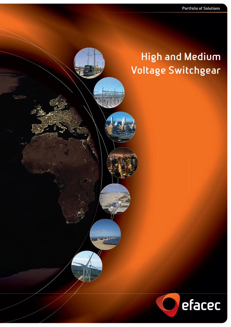
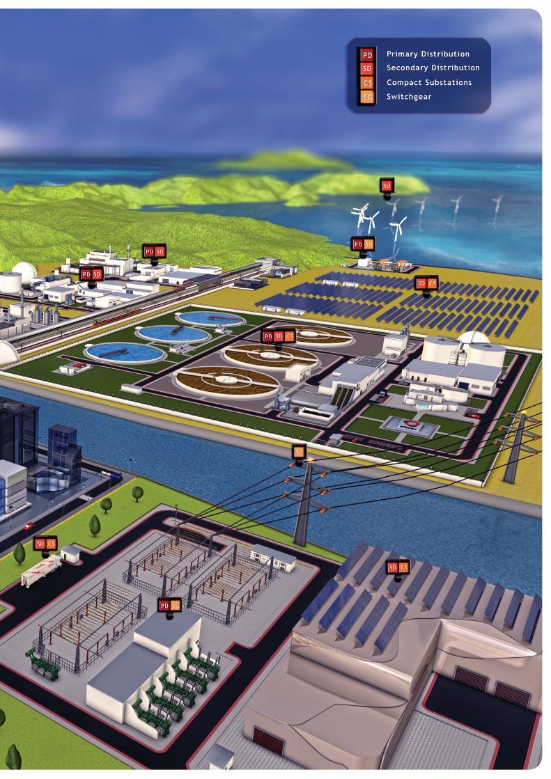
Portfolio of Solutions
High and MediumVoltage Switchgear
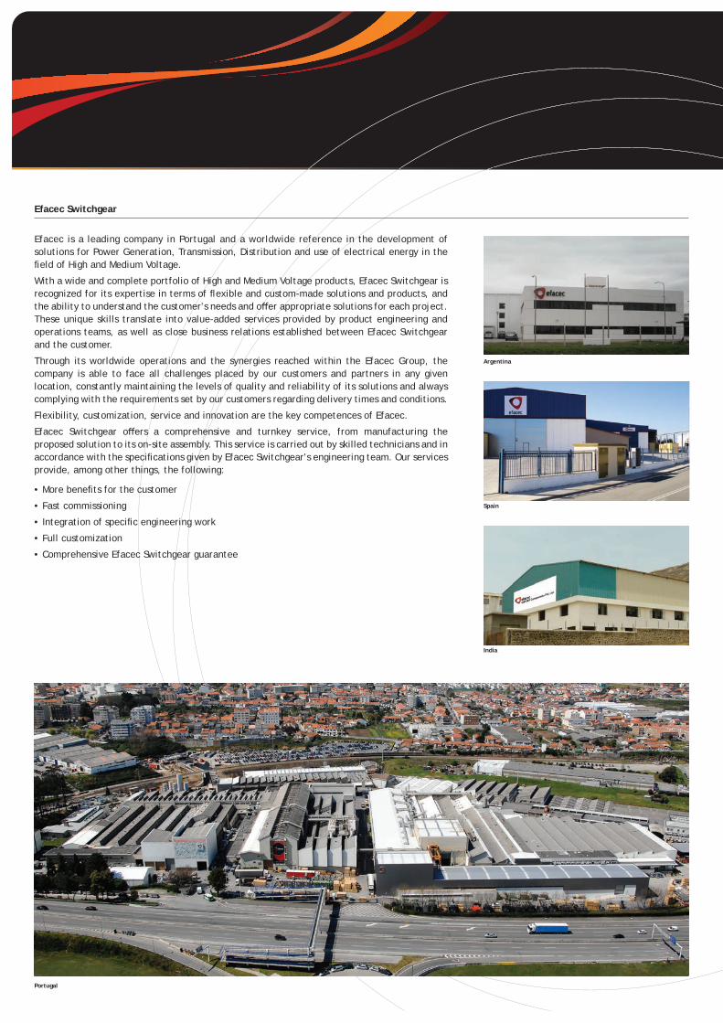
Efacec is a leading company in Portugal and a worldwide reference in the development of solutions for Power Generation, Transmission, Distribution and use of electrical energy in the fi eld of High and Medium Voltage.
With a wide and complete portfolio of High and Medium Voltage products, Efacec Switchgear is recognized for its expertise in terms of fl exible and custom-made solutions and products, and the ability to understand the customer’s needs and off er appropriate solutions for each project. These unique skills translate into value-added services provided by product engineering and operations teams, as well as close business relations established between Efacec Switchgear and the customer.
Through its worldwide operations and the synergies reached within the Efacec Group, the company is able to face all challenges placed by our customers and partners in any given location, constantly maintaining the levels of quality and reliability of its solutions and always complying with the requirements set by our customers regarding delivery times and conditions.
Flexibility, customization, service and innovation are the key competences of Efacec.
Efacec Switchgear off ers a comprehensive and turnkey service, from manufacturing the proposed solution to its on-site assembly. This service is carried out by skilled technicians and in accordance with the specifi cations given by Efacec Switchgear’s engineering team. Our services provide, among other things, the following:
• More benefi ts for the customer
• Fast commissioning
• Integration of specifi c engineering work
• Full customization
• Comprehensive Efacec Switchgear guarantee
Efacec Switchgear
Portugal
Argentina
Spain
India
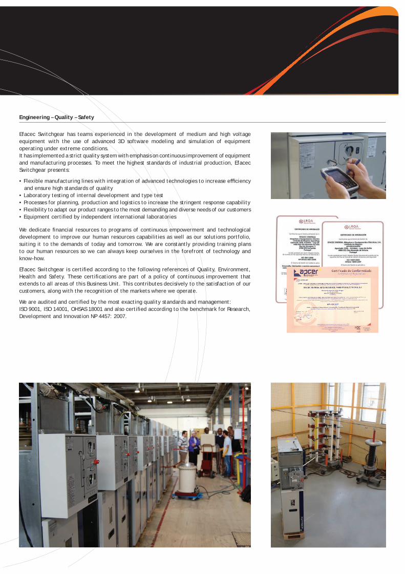
Efacec Switchgear has teams experienced in the development of medium and high voltage equipment with the use of advanced 3D software modeling and simulation of equipment operating under extreme conditions.It has implemented a strict quality system with emphasis on continuous improvement of equipment and manufacturing processes. To meet the highest standards of industrial production, Efacec Switchgear presents:
• Flexible manufacturing lines with integration of advanced technologies to increase effi ciency and ensure high standards of quality• Laboratory testing of internal development and type test• Processes for planning, production and logistics to increase the stringent response capability• Flexibility to adapt our product ranges to the most demanding and diverse needs of our customers• Equipment certifi ed by independent international laboratories
We dedicate fi nancial resources to programs of continuous empowerment and technological development to improve our human resources capabilities as well as our solutions portfolio, suiting it to the demands of today and tomorrow. We are constantly providing training plans to our human resources so we can always keep ourselves in the forefront of technology and know-how.
Efacec Switchgear is certifi ed according to the following references of Quality, Environment, Health and Safety. These certifi cations are part of a policy of continuous improvement that extends to all areas of this Business Unit. This contributes decisively to the satisfaction of our customers, along with the recognition of the markets where we operate.
We are audited and certifi ed by the most exacting quality standards and management:ISO 9001, ISO 14001, OHSAS 18001 and also certifi ed according to the benchmark for Research, Development and Innovation NP 4457: 2007.
Engineering – Quality – Safety
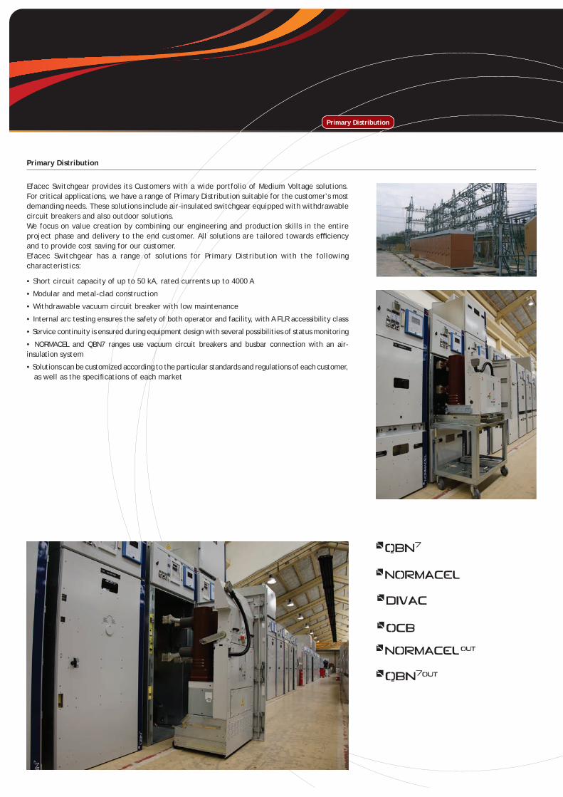
Primary Distribution
Efacec Switchgear provides its Customers with a wide portfolio of Medium Voltage solutions. For critical applications, we have a range of Primary Distribution suitable for the customer’s most demanding needs. These solutions include air-insulated switchgear equipped with withdrawable circuit breakers and also outdoor solutions.We focus on value creation by combining our engineering and production skills in the entire project phase and delivery to the end customer. All solutions are tailored towards effi ciency and to provide cost saving for our customer.Efacec Switchgear has a range of solutions for Primary Distribution with the following characteristics:
• Short circuit capacity of up to 50 kA, rated currents up to 4000 A
• Modular and metal-clad construction
• Withdrawable vacuum circuit breaker with low maintenance
• Internal arc testing ensures the safety of both operator and facility, with A FLR accessibility class
• Service continuity is ensured during equipment design with several possibilities of status monitoring
• NORMACEL and QBN7 ranges use vacuum circuit breakers and busbar connection with an air- insulation system
• Solutions can be customized according to the particular standards and regulations of each customer, as well as the specifi cations of each market
Primary Distribution
• Modular construction
• Expandable
• Small installation area
• Operational simplicity
• Exclusively operated from the front
• Internal arc resistant
• Equipped with a vacuum circuit breaker (E3 and M2 classes), with high electric and mechanical life
• Possibility of wall-mount installation (Special Request)
• Reliable and requires little maintenance
• Insertion/extraction of the circuit breaker with the compartment door closed for full operator safety
• Several optional equipment as specifi ed by the customer
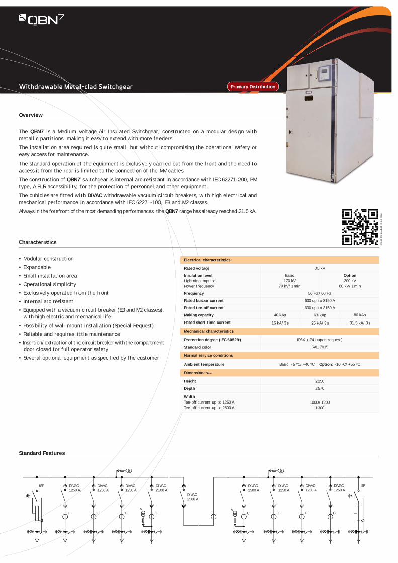
The QBN7 is a Medium Voltage Air Insulated Switchgear, constructed on a modular design with metallic partitions, making it easy to extend with more feeders.
The installation area required is quite small, but without compromising the operational safety or easy access for maintenance.
The standard operation of the equipment is exclusively carried-out from the front and the need to access it from the rear is limited to the connection of the MV cables.
The construction of QBN7 switchgear is internal arc resistant in accordance with IEC 62271-200, PM type, A FLR accessibility, for the protection of personnel and other equipment.
The cubicles are fi tted with DIVAC withdrawable vacuum circuit breakers, with high electrical and mechanical performance in accordance with IEC 62271-100, E3 and M2 classes.
Always in the forefront of the most demanding performances, the QBN7 range has already reached 31.5 kA.
Overview
Characteristics
Standard Features
Primary Distribution
DIVAC1250 A
DIVAC1250 A
DIVAC1250 A
DIVAC2500 A
C
DIVAC2500 A
DIVAC2500 A
DIVAC1250 A
DIVAC1250 A
DIVAC1250 A
ISFISF
VCCC C C C C
V
IP3X (IP41 upon request)
RAL 7035
Basic: - 5 ºC / + 40 ºC | Option: - 10 ºC / + 55 ºC
36 kV
Protection degree (IEC 60529)
Standard color
Ambient temperature
Mechanical characteristics
Normal service conditions
Dimensiones mm
Electrical characteristics
Rated voltage
Insulation levelLightning impulsePower frequency
Frequency
Rated busbar current
Rated tee-off current
Making capacity
Rated short-time current
Basic170 kV
70 kV / 1 min
Option200 kV
80 kV / 1 min
50 Hz / 60 Hz
630 up to 3150 A
630 up to 3150 A
25 kA / 3 s16 kA / 3 s 31.5 kA / 3 s
Height
Depth
Width Tee-off current up to 1250 ATee-off current up to 2500 A
1000 / 12001300
2250
2570
Chec
k th
e pr
oduc
t in
our
pag
e.
Withdrawable Metal-clad Switchgear
63 kAp40 kAp 80 kAp
Withdrawable Metal-clad Switchgear (Simple Busbar)
• Modular construction
• Expandable
• Small installation area
• Operational simplicity
• Exclusively operated from the front
• Internal arc resistant
• Equipped with a vacuum circuit breaker with high electric and mechanical life (E3 and M2 classes) or contactor
• Possibility of wall-mount installation
• Reliable and requires little maintenance
• Insertion/extraction of the circuit breaker with the compartment door closed
• Several optional equipment as specifi ed by the customer
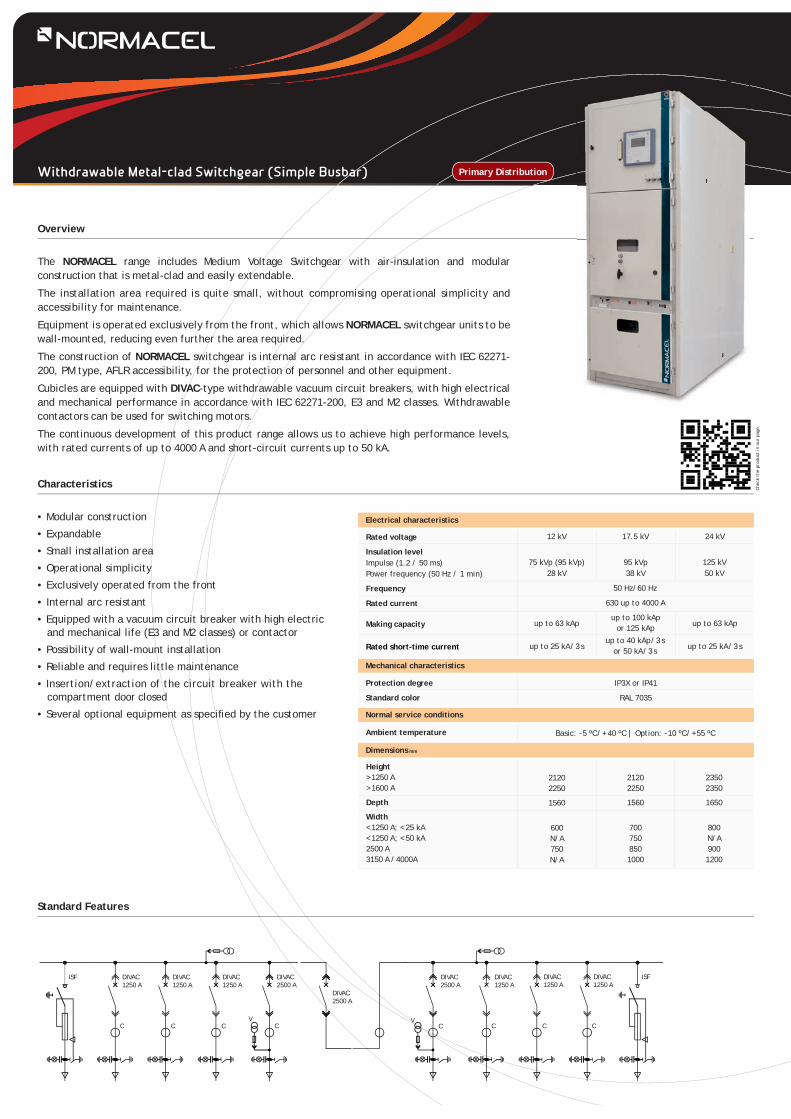
The NORMACEL range includes Medium Voltage Switchgear with air-insulation and modular construction that is metal-clad and easily extendable.
The installation area required is quite small, without compromising operational simplicity and accessibility for maintenance.
Equipment is operated exclusively from the front, which allows NORMACEL switchgear units to be wall-mounted, reducing even further the area required.
The construction of NORMACEL switchgear is internal arc resistant in accordance with IEC 62271-200, PM type, AFLR accessibility, for the protection of personnel and other equipment.
Cubicles are equipped with DIVAC-type withdrawable vacuum circuit breakers, with high electrical and mechanical performance in accordance with IEC 62271-200, E3 and M2 classes. Withdrawable contactors can be used for switching motors.
The continuous development of this product range allows us to achieve high performance levels, with rated currents of up to 4000 A and short-circuit currents up to 50 kA.
Overview
Characteristics
Standard Features
Primary Distribution
DIVAC1250 A
DIVAC1250 A
DIVAC1250 A
DIVAC2500 A
C
DIVAC2500 A
DIVAC2500 A
DIVAC1250 A
DIVAC1250 A
DIVAC1250 A
ISFISF
VCCC C C C C
V
up to 63 kAp up to 63 kApup to 100 kAp
or 125 kApup to 40 kAp / 3 s
or 50 kA / 3 sup to 25 kA / 3 s
IP3X or IP41
RAL 7035
Basic: - 5 ºC / + 40 ºC | Option: - 10 ºC / + 55 ºC
up to 25 kA / 3 s
12 kV 17.5 kV 24 kV
95 kVp38 kV
Rated voltage
Insulation levelImpulse (1.2 / 50 ms)Power frequency (50 Hz / 1 min)
Frequency
Rated current
Making capacity
Rated short-time current
Height > 1250 A> 1600 A
Depth
Width< 1250 A; < 25 kA< 1250 A; < 50 kA2500 A3150 A / 4000A
Protection degree
Standard color
Ambient temperature
Mechanical characteristics
Normal service conditions
Dimensions mm
50 Hz/60 Hz
630 up to 4000 A
75 kVp (95 kVp)28 kV
21202250
1560
7007508501000
21202250
1560
600N/A750N/A
23502350
1650
800N/A9001200
Electrical characteristics
125 kV50 kV
Chec
k th
e pr
oduc
t in
our
pag
e.
• Modular construction
• Extendable
• Small installation area
• Operational simplicity
• Exclusively operated from the front
• Internal arc resistant
• Equipped with a vacuum circuit breaker with high electric and mechanical life (E3 and M2 classes)
• Reliable and requires little maintenance
• Insertion/extraction of the circuit breaker with the compartment door closed
• Several optional equipment as specifi ed by the customer
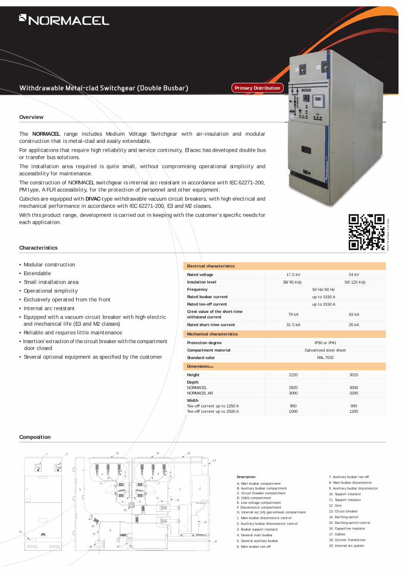
The NORMACEL range includes Medium Voltage Switchgear with air-insulation and modular construction that is metal-clad and easily extendable.
For applications that require high reliability and service continuity, Efacec has developed double bus or transfer bus solutions.
The installation area required is quite small, without compromising operational simplicity and accessibility for maintenance.
The construction of NORMACEL switchgear is internal arc resistant in accordance with IEC 62271-200, PM type, A FLR accessibility, for the protection of personnel and other equipment.
Cubicles are equipped with DIVAC-type withdrawable vacuum circuit breakers, with high electrical and mechanical performance in accordance with IEC 62271-200, E3 and M2 classes.
With this product range, development is carried out in keeping with the customer’s specifi c needs for each application.
Overview
Characteristics
Composition
Withdrawable Metal-clad Switchgear (Double Busbar) Primary Distribution
Description:
A. Main busbar compartmentB. Auxiliary busbar compartmentC. Circuit breaker compartmentD. Cable compartmentE. Low-voltage compartmentF. Disconnector compartmentG. Internal arc (IA) gas exhaust compartment
1. Main busbar disconnector control
2. Auxiliary busbar disconnector control
3. Busbar support insulator
4. General main busbar
5. General auxiliary busbar
6. Main busbar tee-off
7. Auxiliary busbar tee-off
8. Main busbar disconnector
9. Auxiliary busbar disconnector
10. Support insulator
11. Support insulator
12. Grid
13. Circuit breaker
14. Earthing switch
15. Earthing switch control
16. Capacitive insulator
17. Cables
18. Current Transformer
19. Internal arc system
Electrical characteristics
17.5 kV
79 kA
31.5 kA
Rated voltage
Insulation level
Frequency
Rated busbar current
Rated tee-off current
Crest value of the short-time withstand current
Rated short-time current
Protection degree
Compartment material
Standard color
IP30 or IP41
Galvanized steel sheet
RAL 7032
Height
Depth NORMACELNORMACEL AR
WidthTee-off current up to 1250 ATee-off current up to 2500 A
2220
28203000
8501000
Chec
k th
e pr
oduc
t in
our
pag
e.
19 19 19
1_2
3
4
98
10
6
A
17
16
18
D
14
F
EC
12
3
5B
7
11
G
13
15
1 2
15
Mechanical characteristics
Dimensions mm
3015
30003200
9001200
24 kV
63 kA
25 kA
38/95 kVp 50/125 kVp
50 Hz/60 Hz
up to 3150 A
up to 3150 A
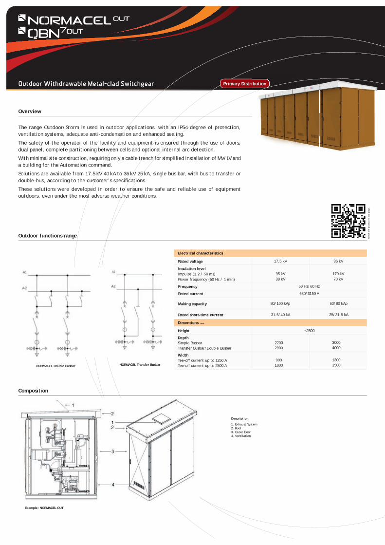
The range Outdoor/Storm is used in outdoor applications, with an IP54 degree of protection, ventilation systems, adequate anti-condensation and enhanced sealing.
The safety of the operator of the facility and equipment is ensured through the use of doors, dual panel, complete partitioning between cells and optional internal arc detection.
With minimal site construction, requiring only a cable trench for simplifi ed installation of MV/LV and a building for the Automation command.
Solutions are available from 17.5 kV 40 kA to 36 kV 25 kA, single bus bar, with bus to transfer or double-bus, according to the customer’s specifi cations.
These solutions were developed in order to ensure the safe and reliable use of equipment outdoors, even under the most adverse weather conditions.
Overview
Outdoor functions range
Composition
Outdoor Withdrawable Metal-clad Switchgear Primary Distribution
Chec
k th
e pr
oduc
t in
our
pag
e.
ibution
80/100 kAp 63/80 kAp
31.5/40 kA 25/31.5 kA
17.5 kV 36 kVRated voltage
Insulation levelImpulse (1.2 / 50 ms)Power frequency (50 Hz / 1 min)
Frequency
Rated current
Making capacity
Rated short-time current
50 Hz/60 Hz
630/3150 A
95 kV38 kV
Electrical characteristics
170 kV70 kV
NORMACEL Double Busbar NORMACEL Transfer Busbar
Example: NORMACEL OUT
Description:
1. Exhaust System2. Roof3. Outer Door4. Ventilation
Height
DepthSimple BusbarTransfer Busbar/Double Busbar
WidthTee-off current up to 1250 ATee-off current up to 2500 A
22002900
9001000
Dimensions mm
30004000
13001500
<2500
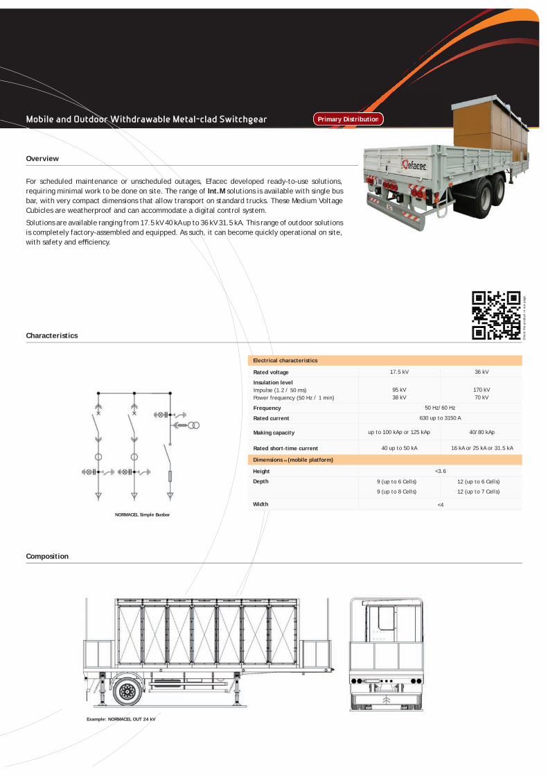
For scheduled maintenance or unscheduled outages, Efacec developed ready-to-use solutions, requiring minimal work to be done on site. The range of Int.M solutions is available with single bus bar, with very compact dimensions that allow transport on standard trucks. These Medium Voltage Cubicles are weatherproof and can accommodate a digital control system.
Solutions are available ranging from 17.5 kV 40 kA up to 36 kV 31.5 kA. This range of outdoor solutions is completely factory-assembled and equipped. As such, it can become quickly operational on site, with safety and effi ciency.
Overview
Characteristics
Composition
Mobile and Outdoor Withdrawable Metal-clad Switchgear Primary Distribution
up to 100 kAp or 125 kAp 40/80 kAp
40 up to 50 kA 16 kA or 25 kA or 31.5 kA
17.5 kV 36 kVRated voltage
Insulation levelImpulse (1.2 / 50 ms)Power frequency (50 Hz / 1 min)
Frequency
Rated current
Making capacity
Rated short-time current
50 Hz/60 Hz
630 up to 3150 A
95 kV38 kV
Electrical characteristics
170 kV70 kV
Example: NORMACEL OUT 24 kV
Chec
k th
e pr
oduc
t in
our
pag
e.
Height
Depth
Width
9 (up to 6 Cells)
9 (up to 8 Cells)
Dimensions m (mobile platform)
<3.6
12 (up to 6 Cells)
12 (up to 7 Cells)
NORMACEL Simple Busbar
<4
ibution
• Safe and reliable
• Compact design
• Ideal for all Medium Voltage applications
• Excellent dielectric properties
• Excellent arc extinguishing properties
• Easy to install
• Easy switching operation
• High electric and mechanical life
• Maintenance free
• Several options available
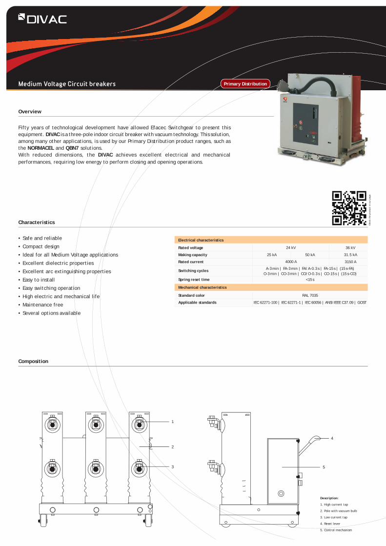
Fifty years of technological development have allowed Efacec Switchgear to present this equipment. DIVAC is a three-pole indoor circuit breaker with vacuum technology. This solution, among many other applications, is used by our Primary Distribution product ranges, such as the NORMACEL and QBN7 solutions.With reduced dimensions, the DIVAC achieves excellent electrical and mechanical performances, requiring low energy to perform closing and opening operations.
Overview
Characteristics
Composition
Primary Distribution
Description:
1. High current tap
2. Pole with vacuum bulb
3. Low current tap
4. Reset lever
5. Control mechanism
4
5
1
2
3
Standard color
Applicable standards
Mechanical characteristics
Electrical characteristics
Rated voltage
Making capacity
Rated current
Switching cycles
Spring reset time
A-3 min | FA-3 min | FA/A-0.3 s | FA-15 s | (15 s-FA)O-3 min | CO-3 min | CO/O-0.3 s | CO-15 s | (15 s-CO)
50 kA25 kA
24 kV
4000 A
36 kV
31.5 kA
3150 A
<15 s
RAL 7035
IEC 62271-100 | IEC 62271-1 | IEC 60056 | ANSI IEEE C37.09 | GOST
Chec
k th
e pr
oduc
t in
our
pag
e.
Medium Voltage Circuit breakers
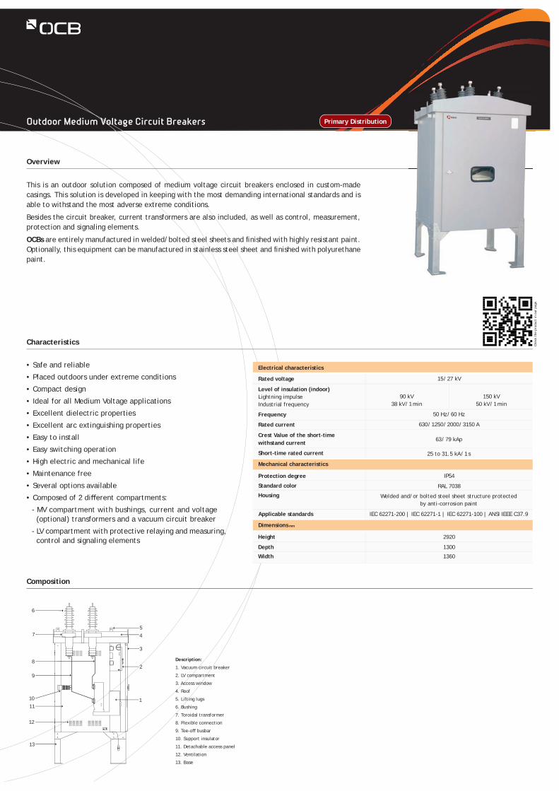
This is an outdoor solution composed of medium voltage circuit breakers enclosed in custom-made casings. This solution is developed in keeping with the most demanding international standards and is able to withstand the most adverse extreme conditions.
Besides the circuit breaker, current transformers are also included, as well as control, measurement, protection and signaling elements.
OCBs are entirely manufactured in welded/bolted steel sheets and fi nished with highly resistant paint. Optionally, this equipment can be manufactured in stainless steel sheet and fi nished with polyurethane paint.
Overview
Characteristics
Composition
Primary Distribution
Description:
1. Vacuum circuit breaker
2. LV compartment
3. Access window
4. Roof
5. Lifting lugs
6. Bushing
7. Toroidal transformer
8. Flexible connection
9. Tee-off busbar
10. Support insulator
11. Detachable access panel
12. Ventilation
13. Base
1
8
9
1011
12
13
6
754
3
2
IP54
RAL 7038
Welded and/or bolted steel sheet structure protected by anti-corrosion paint
15 / 27 kV
Protection degree
Standard color
Housing
Mechanical characteristics
Dimensions mm
Electrical characteristics
Rated voltage
Level of insulation (indoor)Lightning impulseIndustrial frequency
Frequency
Rated current
Crest Value of the short-timewithstand current
Short-time rated current
90 kV38 kV / 1 min
150 kV50 kV / 1 min
50 Hz / 60 Hz
630 / 1250 / 2000 / 3150 A
63 / 79 kAp
25 to 31.5 kA / 1 s
Height
Depth
Width 1360
2920
1300
Applicable standards IEC 62271-200 | IEC 62271-1 | IEC 62271-100 | ANSI IEEE C37.9
Chec
k th
e pr
oduc
t in
our
pag
e.
• Safe and reliable
• Placed outdoors under extreme conditions
• Compact design
• Ideal for all Medium Voltage applications
• Excellent dielectric properties
• Excellent arc extinguishing properties
• Easy to install
• Easy switching operation
• High electric and mechanical life
• Maintenance free
• Several options available
• Composed of 2 diff erent compartments:
- MV compartment with bushings, current and voltage (optional) transformers and a vacuum circuit breaker
- LV compartment with protective relaying and measuring, control and signaling elements
Outdoor Medium Voltage Circuit Breakers
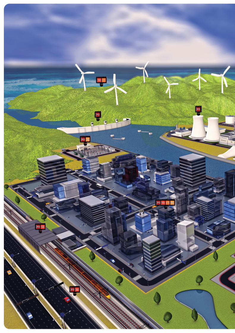
Keeping in mind future trends as well as the demand for effi cient and modular solutions, Efacec Switchgear has been providing solutions adequate for the customer’s needs in any location and under environmental conditions that require Secondary Distribution solutions.
As such, we are able to present indoor and outdoor solutions to the customer, such as gas-insulated (RMU) or air-insulated cubicles with several available features. Environmental guidelines are fully implemented in these solutions to cover the entire operating life of the equipment, covering design, production and commissioning.
Efacec Switchgear’s range of solutions for Secondary Distribution has the following characteristics:
• Short circuit capacity up to 20 kA, rated currents up to 1250 A
• Modular and compartmentalized construction
• Withdrawable vacuum circuit breaker with low maintenance and replaceable components
• Internal arc testing ensures the safety of both operator and facility, with AFL and/or AFLR accessibility class lasting up to 1s
• Service continuity is ensured during equipment design with several tools for status monitoring;
• The NORMAFIX range uses vacuum circuit breakers
• The FLUOFIX range uses vacuum circuit breakers
• Solutions can be customized according to the particular standards and regulations of each customer, as well as the specifi cations for each geographical market
Secondary Distribution
Secondary Distribution
Overview
Characteristics
Standard Features
TA RN SC DCNE
DIVAC
M
SFSFSF
SFISF ISF
IS CIS SBM TT CDDB
Note: Dimensions are for reference purposes only.
Secondary Distribution
Dimensions mm
Height
Depth
Width
2010
1155
600 / 1200
Electrical characteristics
16 kA / 3 s; 20 kA / 1 s
630 / 1250 A
1575
860
375 / 500 / 750 / 1000
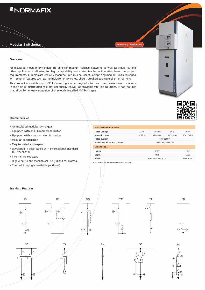
• Air-insulated modular switchgear
• Equipped with an SF6 load break switch
• Equipped with a vacuum circuit breaker
• Modular construction
• Easy to install and expand
• Developed in accordance with International Standard IEC 62271-200
• Internal arc resistant
• High electric and mechanical life (E3 and M2 classes)
• Thermal imaging is available (optional)
Rated voltage
Insulation level
Rated current
Short-time withstand current
12 kV
28 / 75 kV
17.5 kV
38 / 95 kV
24 kV
50 / 125 kV
36 kV
70 / 170 kV
Air-insulated modular switchgear suitable for medium voltage networks as well as industries and other applications, allowing for high adaptability and customizable confi guration based on project requirements. Cubicles are entirely manufactured in steel sheet, comprising modular units equipped with several features such as the inclusion of switches, circuit breakers and several other options.
This product is available up to 36 kV covering a wide range of solutions to suit various world markets in the fi eld of distribution of electrical energy. As well as providing multiple solutions, it has features that allow for an easy expansion of previously installed MV Switchgear.
Chec
k th
e pr
oduc
t in
our
pag
e.
Modular Switchgear
TI TI TITT
TI
Overview
Characteristics
Standard Features
Secondary Distribution
• Compact switchgear with SF6 insulation
• Equipped with an SF6 load break switch
• Equipped with a vacuum circuit breaker
• Developed in accordance with International Standard IEC 62271-200
• Unaff ected by weather conditions
• Compact or modular version
• Internal arc resistant
• High electric and mechanical life (E3 and M2 classes)
• Stainless steel tank
CD IS CIS M SB DC
DIVAC
M
ISF G
ISF GISF G
TI
ISF G
TT
Note: Dimensions are for reference purposes only.
-25 ºC / + 40 ºC (others, upon request)
Rated voltage
Insulation levelImpulse (1.2 / 50 ms)Power frequency (50 Hz / 1 min)
Rated current
Short-time rated current
Temperature
Dimensions mm
up to 630 A
Height
Depth
Width
1275
727
375 / 450 / 750
1728
900
450 / 1000
Electrical characteristics
16 kA / 3 s; 20 kA / 3 s
12 kV 17.5 kV 24 kV 36 kV
28 kVp 75 kV
38 kVp95 kV
50 kVp125 kV
70 kVp170 kV
This solution has modular and compact cubicles with full SF6 insulation for medium voltage networks up to 36 kV. It is a modular solution for easy installation due to its dimensions and weight.
Operational safety is ensured by tests carried out in conformity with the most demanding standards, including the construction and weather resistance of the solutions. This solution allows for numerous confi gurations as well as the incorporation of several options in keeping with the demands of the customer.
The reduced dimensions allow for installation in compact substations. Available with up to 5 functions in a single stainless steel hermetically isolated tank, which ensures the protection of its active components against harsh environments.
It is available in a compact version that minimizes on-site work and a modular version that maximizes diff erent function settings.
Chec
k th
e pr
oduc
t in
our
pag
e.
Compact Switchgear
IP67 (for the medium voltage compartment) Protection degrees
Mechanical characteristics
2IS + CIS 2IS + DC3IS 3IS + 2CIS
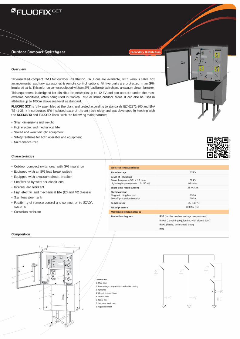
SF6-insulated compact RMU for outdoor installation. Solutions are available, with various cable box arrangements, auxiliary accessories & remote control options. All live parts are protected in an SF6-insulated tank. This solution comes equipped with an SF6 load break switch and a vacuum circuit breaker.
This equipment is designed for distribution networks up to 12 kV and can operate under the most extreme conditions, often being used in tropical, arid or saline outdoor areas. It can also be used in altitudes up to 1000m above sea level as standard.
FLUOFIX GCT is fully assembled at the plant and tested according to standards IEC 62271-200 and ENA TS 41-36. It incorporates SF6-insulated state-of-the-art technology and was developed in keeping with the NORMAFIX and FLUOFIX lines, with the following main features:
• Small dimensions and weight• High electric and mechanical life• Sealed and weathertight equipment• Safety features for both operator and equipment• Maintenance-free
Overview
Characteristics
Composition
Secondary Distribution
Description:
1. Main door
2. Low voltage compartment and cable testing
3. Synoptic
4. Circuit breaker lever
5. Switch lever
6. Cable box
7. Stainless steel tank
8. Adjustable feet
• Outdoor compact switchgear with SF6 insulation
• Equipped with an SF6 load break switch
• Equipped with a vacuum circuit breaker
• Unaffected by weather conditions
• Internal arc resistant
• High electric and mechanical life (E3 and M2 classes)
• Stainless steel tank
• Possibility of remote control and connection to SCADA systems
• Corrosion resistantIPX7 (for the medium voltage compartment)
IP3XW (remaining equipment with closed door)
IP2XC (fascia, with closed door)
IK08
12 kV
Temperature
Rated pressure
Protection degrees
Electrical characteristics
Rated voltage
Level of insulationPower frequency (50 Hz / 1 min) Lightning impulse (wave 1.2 / 50 ms)
Short-time rated current
Rated currentRing switching functionTee-off protection function
38 kV95 kV máx
21 kA /3 s
- 25 / + 40 ºC
0.3 Bar (rel)
Mechanical characteristics
630 A200 A
Chec
k th
e pr
oduc
t in
our
pag
e.
Outdoor Compact Switchgear
• Flexile• Reliable• Remotely controlled• Long service life (10 000 mechanical manoeuvres)• Ideal for adverse environmental conditions• Compact equipment design• Simple and fl exible installation• Adapted to any type of pole assemblies• Few mechanical parts, minimal maintenance • Prepared for smart automation of distribution networks
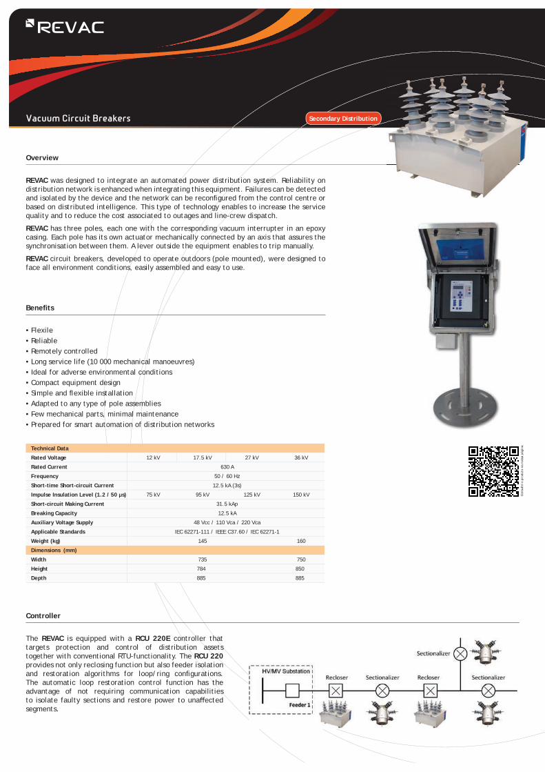
REVAC was designed to integrate an automated power distribution system. Reliability on distribution network is enhanced when integrating this equipment. Failures can be detected and isolated by the device and the network can be reconfi gured from the control centre or based on distributed intelligence. This type of technology enables to increase the service quality and to reduce the cost associated to outages and line-crew dispatch.
REVAC has three poles, each one with the corresponding vacuum interrupter in an epoxy casing. Each pole has its own actuator mechanically connected by an axis that assures the synchronisation between them. A lever outside the equipment enables to trip manually.
REVAC circuit breakers, developed to operate outdoors (pole mounted), were designed to face all environment conditions, easily assembled and easy to use.
The REVAC is equipped with a RCU 220E controller that targets protection and control of distribution assets together with conventional RTU-functionality. The RCU 220 provides not only reclosing function but also feeder isolation and restoration algorithms for loop/ring confi gurations. The automatic loop restoration control function has the advantage of not requiring communication capabilities to isolate faulty sections and restore power to unaff ected segments.
Overview
Controller
Benefi ts
Cons
ulte
o p
rodu
to n
a no
ssa
pági
na.
Technical Data
Rated Voltage 12 kV 17.5 kV 27 kV 36 kV
Rated Current 630 A
Frequency 50 / 60 Hz
Short-time Short-circuit Current 12.5 kA (3s)
Impulse Insulation Level (1.2 / 50 μs) 75 kV 95 kV 125 kV 150 kV
Short-circuit Making Current 31.5 kAp
Breaking Capacity 12.5 kA
Auxiliary Voltage Supply 48 Vcc / 110 Vca / 220 Vca
Applicable Standards IEC 62271-111 / IEEE C37.60 / IEC 62271-1
Weight (kg) 145 160
Dimensions (mm)
Width 735 750
Height 784 850
Depth 885 885
Vacuum Circuit Breakers Secondary Distribution
• Reliable
• Compact and light
• Suitable for all kinds of poles
• Ideal for extreme weather conditions
• Not hazardous to the environment
• Easy to install
• Easy to operate
• Remote control and monitoring via radio
• Simple and safe (mechanical and electric) interlocks
• High electric and mechanical life
• Maintenance free
• Several options available
IATS is an SF6 load break switch for pole-mounting. All live parts are protected against environmental hazards inside an SF6-fi lled compartment. The switch is sealed for life in a stainless steel tank.
IATS was designed to be used outdoors, in power distribution facilities, under the most extreme conditions. This equipment is particularly suitable for industrial (dust, sand), tropical, arid and saline environments. It can be used at altitudes above 1000 m of altitude.
IATS is assembled and tested according to standard IEC 60265. The increasing demands regarding people and equipment protection are taken into consideration by Efacec Switchgear during the development and design of this equipment.
Overview
Characteristics
Standard Features
• Command center- SCADA- Microprocessor- Control unit- Computers- Radio- Modem- Antenna
• Control cabinet- Local pushbuttons- Local/remote- Battery and battery charger- Heat resistant- Microprocessor- Remote control unit- Signal inputs / outputs- Radio- Modem- Antenna- Fault detection relay
• SF6 load break switch- Motor- Transformers- SF6 low pressure alarm
• Mechanical actuator- Switching lever- Interlocks
Command center
Control cabinet
IATS
12 kV
75 kVp28 Kv
17.5 kV
95 kVp38 Kv
24 kV
125 kVp50 Kv
36 kV
170 kVp70 Kv
400 A or 630 A
12.5 kA / 3 s; 16 kA /3 s
31.5 / 40 kA
630 A
630 A
25 A
Mechanical characteristics
Protection degrees(IEC 60529 y EN 50102)
Standards
IP54 (mechanism compartments)IP67 (MV compartments)
IEC60265 | HN 64 S46
Rated voltage
Level of insulationPower frequency (50 Hz / 1 min) Lightning impulse (wave 1,2 / 50 ms)
Rated current
Short-time short-circuit current
Short circuit making current
Breaking current: mainly active load
Breaking current: closed loop
Breaking current: cable charging
Ambient temperature
Mechanical endurance
- 25 ºC / + 40 ºC (others, upon request)
2.000 operations
Electrical characteristics
Chec
k th
e pr
oduc
t in
our
pag
e.
Switches
Example of IATS
Secondary Distribution
For high and medium voltage power distribution, Efacec Switchgear provides a set of solutions up to 550 kV. The range of solutions for High and Medium Voltage Switchgear includes disconnectors, circuit breakers, withdrawable circuit breakers and switches.Efacec Switchgear has been developing solutions by using the most advanced IT resources with the purpose of increasing the performance of said equipment.The guarantee of an excellent mechanical and electrical performance of the High and Medium Voltage Switchgear solutions is evidenced by the documentation concerning all type and routine tests that were carried out, taking into account all kinds of equipment installation, even those under the most adverse conditions (seismic areas or extreme temperatures).Efacec Switchgear’s range of solutions for High and Medium Voltage Switchgear has the following characteristics:
• High voltage disconnectors include several options and can be transported while assembled at lower voltages or in modules at higher voltages
• Allow for manual, motor, local or remote operation by using a control capable of operating all poles simultaneously or individually, as per the needs of the customer
• Easy installation and maintenance with economic and fi nancial gains
• Short breaking times
• Highly effi cient and adequate materials
• Solutions with type tests in accordance with current IEC standards, guarantee to the customer that the device reaches the intended ratings
High and Medium Voltage Switchgear
AparatosSwitchgear
Switchgear
• Up to 245 kV
• Up to 50 kA (rms)/4000 A
• Easy installation and maintenance
• IEC/ANSI certifi cation
• Seismic-resistant
• Ice-resistant
• Double side break/center break
These two or three-column disconnectors include center break (SHD) or double side break (SHCR), have separate poles and are for outdoor installation. They can be supplied with manual, motor, local or remote control.Closing and opening operations are made by rotating the movable contact blade in a horizontal plane. Optionally, this equipment can also be supplied for vertical or suspended mounting.
Overview
Characteristics
Standard Features
tchgear
SHD SHCR SH1R
Rated voltage
Lightning impulse withstand voltage
To earth and between poles
Across the insulating distance
Power frequency withstand voltage
To earth and between poles
Dry Rain
Rated withstand current
Short-timeRIV test
HV (1 MHz)Rated permanent
current
Dry Rain
(kVrms)(kVrms)
(kVp) (kVp)Type
SH1R-36
SHD-170SHD-245
SHD-24
SHD-36SHCR-36SH1R-72.5SHD-72.5SHCR-72.5
SHD-145
SHCR-145
SHD-123
ANSI
Dimensões mm |Peso kg
60 80 80 100 120 120 130 180 250 250 220 280 250 410
24 25.8
750 750 860 825 325 385 325 315 375 424 3751050 900 1200 990 460 465 460 385 530 512 530
up to 2000 up to 2000
up to 2000 up to 2000
up to 3150 up to 3000
up to 3150 up to 3000
up to 3150 up to 3000
up to 3150 up to 3000 up to 3150 up to 3000
up to 2000 up to 2000
up to 2000 up to 2000
up to 2000 up to 2000
up to 2000 up to 2000
up to 3150
up to 2000 up to 2000
125 150
170 200
325 350
450
145 165 50 70 50 60 60 77 6031.5 25 80 65
195 220 70 95 70 80 80 105 8031.5 2550 44
80 65
375 385
520 185 185
160 193
210
160
210SHD-100
SHCR-123230 280 230 230 265 308 265
650 650 750 715 275 335 275 275 315 369 315
Dimensions mm
ModelA
B
D1
D2
E
H
Weight
Across the insulating distance
Dimensões mm |Peso kgMass kg
SH1R 24
495
390
-
765
695
195
SH1R 36
600
530
-
905
800
445
SHD 36
920
420
765
920
900
445
SH1R 72
1240
830
1086
-
1100
770
SHD 72
1195
569
1035
1195
1370
770
SHCR 72
1700
480
969
1175
1360
770
SHD 100
1445
569
1285
1445
1570
1020
SHCR 100
2100
668
1219
1425
1760
1020
SHD 123
1665
796
1505
1665
1790
1220
SHCR 123
2200
714
1419
1625
1860
1220
SHD 145
1945
898
1797
1945
1990
1500
SHCR 145
2600
902
1739
1945
2300
1500
SHD 170
2180
1000
1997
2180
2290
1700
SHD 245
2820
1360
2783
2820
2870
2300
Chec
k th
e pr
oduc
t in
our
pag
e.
100
72.5 72.5
123 121
145 145
170 169
245 242
up to 3150 up to 3000 50 40 125 114
36 38 125 114
125 11450 44
140 175 140 140
31.5 25 80 65
50 44
50 44
50 44
50 44
50 4450 44
50
125 114
125 114
125 114
125 114
125 114125 114
125
up to 3150 up to 3000
ANSI
(A)(kV)
550 550 630 605
<2500 μV <500 μV
SH1R-24
IEC
Horizontal Break Disconnectors
kA (rms)
kAp
AparatosSwitchgear
• Up to 245 kV
• Up to 50 kA (rms)/3150 A
• Easy installation and maintenance
• IEC/ANSI certifi cation
• Seismic-resistant
• Ice-resistant
• Supply option with earth switch included
This rotating vertical break disconnector is intended for outdoor installation. It is composed of three insulators, two of them fi xed (support) and a switching rod. Operation is made by means of motor control and, optionally, can be supplied with manual control, motor, local or remote control.
Closing and opening operations are made by rotation (SVN) or translation (SVL) of the switching rods and mechanisms, which rotate the blade around the shaft itself during opening/closing and rotate it in a vertical plane during the transition between the opening and closing positions.
Overview
Characteristics
Standard Features
geaar
SVL SVN
Rated voltage
To earth and between poles
Across the isolating distance
Power frequency withstand voltage
To earth and between poles
Across the isolating distance
Dry Rain
Rated withstand current
Short-timeRIV test
HV (1 MHz)Rated permanent
current
Dry Rain
(kVrms)(kVrms)
(kVrms) (AMPS) (kVp) (kVp)Type
36 38
72.5 72.5
100 450 520
630 605
750 715
185
230 280
275 335
325 385
460 545
185
230 230
275 275
325 315
460 455
210
265 308
315 368
375 423
530 600
210
265 308
315 368
530 423
530 600
123 121
145 145
170 169
245 242
<2500 μV <500 μV
up to 1250 A up to 1200 A
up to 3150 A up to 3000 A
170 200
325 350
550 550
650 650
750 750 860 825
1050 1050 1200 1155
195 220 70 95 70 80 80 105 80 88 40 38
50 38
100 61
100 61
375 385 140 175 140 145 160 176 160 154
SVL-36
SVN-72.5
SVL-72.5
SVN-100
SVN-123
SVN-145
SVN-245
SVN-170
Dimensions mm
ModelA
B
C
D
E
H
Weight 75 125 140 200 240 280 360 550
Mass kg
SVL-36
1100
1315
840
625
900
445
SVL-72.5
1450
1915
1160
950
1250
770
SVN-72.5
1940
2105
1180
980
1675
770
SVN-100
2140
2550
1430
1230
1875
1020
SVN-123
2440
3005
1630
1430
2175
1220
SVN-145
2640
3535
1910
1710
2375
1500
SVN-170
2790
3835
2110
1910
2525
1700
SVN-245
3490
5220
2784
2583
2840
2300
Chec
k th
e pr
oduc
t in
our
pag
e.
ANSIANSIIEC
Vertical Break Disconnectors
Lightning impulse withstand voltage
kA (rms)
kAp
Switchgear
• Up to 420 kV
• Up to 50 kA (rms)/4000 A
• Easy installation and maintenance
• IEC/ANSI certifi cation
• Seismic-resistant
• Ice-resistant
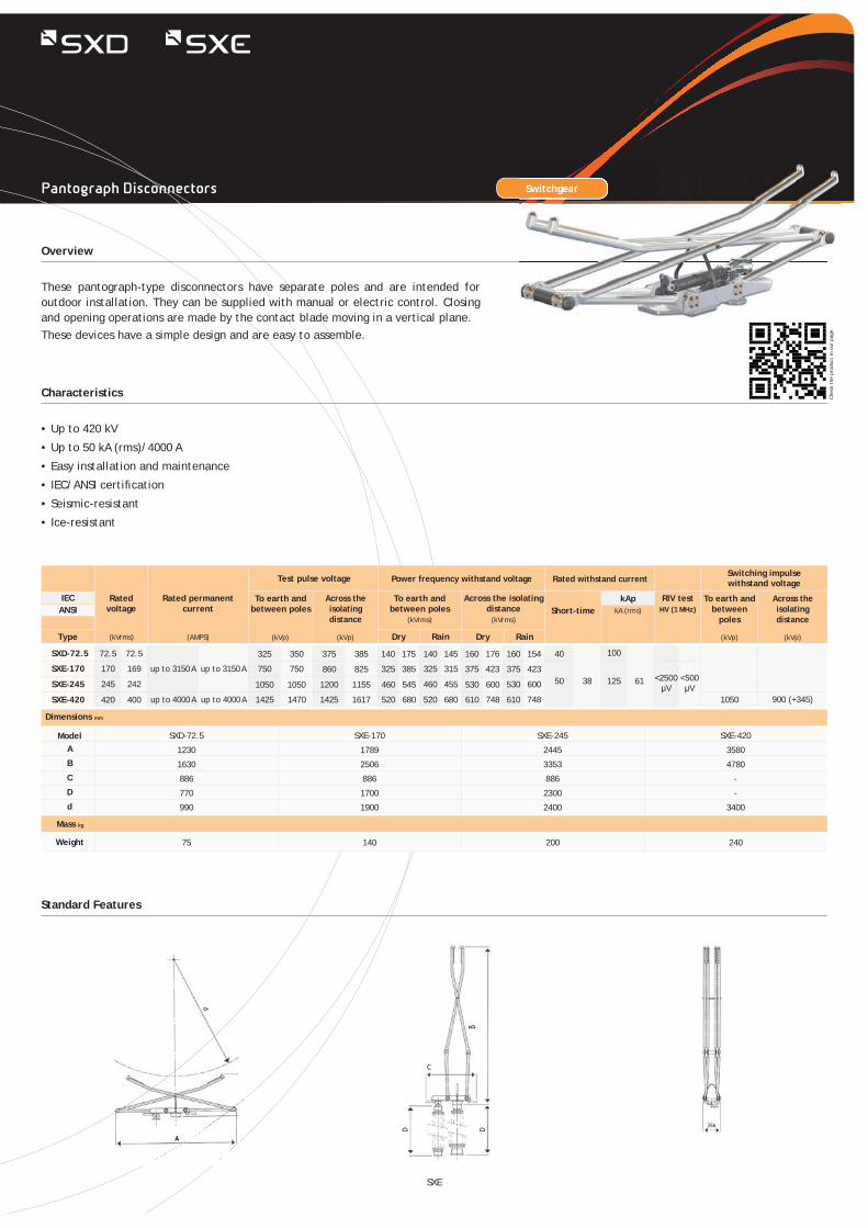
These pantograph-type disconnectors have separate poles and are intended for outdoor installation. They can be supplied with manual or electric control. Closing and opening operations are made by the contact blade moving in a vertical plane.These devices have a simple design and are easy to assemble.
Overview
Characteristics
Standard Features
Switchgear
Rated voltage
Test pulse voltage
To earth and between poles
Across the isolating distance
Power frequency withstand voltage
To earth and between poles
Across the isolating distance
Dry Rain
Rated withstand currentSwitching impulsewithstand voltage
Short-timeTo earth and
between poles
RIV testHV (1 MHz)
Rated permanent current
Dry Rain
(kVrms)(kVrms)
(kVrms) (AMPS) (kVp) (kVp)(kVp) (kVp)Type
Across the isolating distance
72.5 72.5
170 169
245 242
1425 1470 1425 1617
1200 1155
520 680
460 545
520 680
460 455
610 748
530 600
610 748 1050
530 600<2500μV
<500μV
420 400 up to 4000 A up to 4000 A
up to 3150 A up to 3150 A
325 350
750 750
1050 1050
375 385 140 175 140 145 160 176 160 154
50 38
40
125 61
100
860 825 325 385 325 315 375 423 375 423SXE-170
SXD-72.5
SXE-245
SXE-420
ECANSI
Dimensions mm
ModelA
B
C
D
d
Weight
SXD-72.5
1230
1630
886
770
990
SXE-170
1789
2506
886
1700
1900
SXE-245
2445
3353
886
2300
2400
SXE-420
3580
4780
-
-
3400
75 140 200 240
900 (+345)
Mass kgCh
eck
the
prod
uct
in o
ur p
age.
ANSIIEC
Pantograph Disconnectors
SXE
kA (rms)
kAp
AparatosSwitchgear
• Up to 550 kV
• Up to 63 kA (rms)/3150 A
• Easy installation and maintenance
• IEC/ANSI certifi cation
• Seismic-resistant
• Ice-resistant
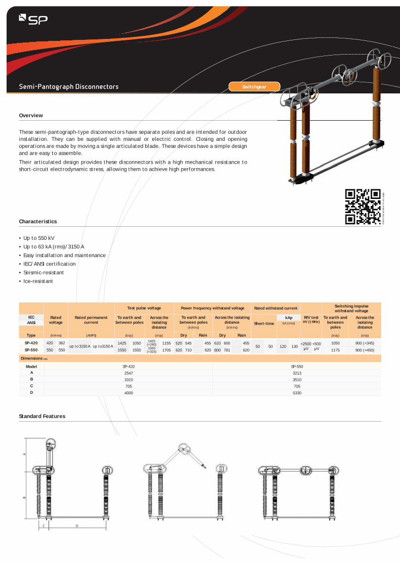
These semi-pantograph-type disconnectors have separate poles and are intended for outdoor installation. They can be supplied with manual or electric control. Closing and opening operations are made by moving a single articulated blade. These devices have a simple design and are easy to assemble.
Their articulated design provides these disconnectors with a high mechanical resistance to short-circuit electrodynamic stress, allowing them to achieve high performances.
Overview
Characteristics
Standard Features
Rated voltage
Test pulse voltage
To earth and between poles
Across the isolating distance
Power frequency withstand voltage
To earth and between poles
Across the isolating distance
Dry Rain
Rated withstand current Switching impulsewithstand voltage
Short-timeTo earth and
between poles
RIV testHV (1 MHz)
Rated permanent current
Dry Rain
(kVrms)(kVrms)
(kVrms) (AMPS) (kVp) (kVp)(kVp) (kVp)Type
Across the isolating distance
420 362
550 550
1050
1175up to 3150 A up to3150 A
1425 1050
1550 1550
1155 520 545 455 610 600 45550 50 120 130
1705 620 710 620 800 781 620SP-550
SP-420 900 (+345)
900 (+450)
1425 (+240)1550
(+315)
<2500μV
<500μV
ModelA
B
C
D
SP-420
2547
3310
705
4000
SP-550
3213
3510
705
5330
Dimensions mm
Chec
k th
e pr
oduc
t in
our
pag
e.
ECANSIANSIIEC
Semi-Pantograph Disconnectors
kA (rms)
kAp
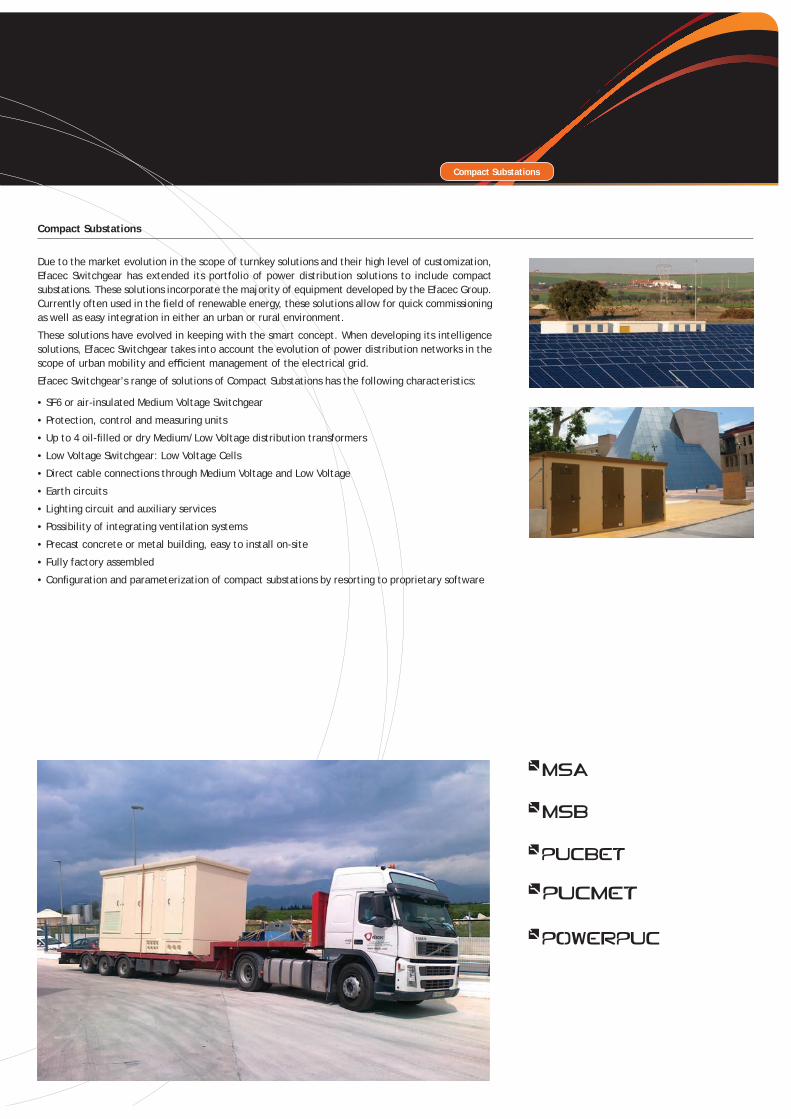
Due to the market evolution in the scope of turnkey solutions and their high level of customization, Efacec Switchgear has extended its portfolio of power distribution solutions to include compact substations. These solutions incorporate the majority of equipment developed by the Efacec Group. Currently often used in the fi eld of renewable energy, these solutions allow for quick commissioning as well as easy integration in either an urban or rural environment.
These solutions have evolved in keeping with the smart concept. When developing its intelligence solutions, Efacec Switchgear takes into account the evolution of power distribution networks in the scope of urban mobility and effi cient management of the electrical grid.
Efacec Switchgear’s range of solutions of Compact Substations has the following characteristics:
• SF6 or air-insulated Medium Voltage Switchgear
• Protection, control and measuring units
• Up to 4 oil-fi lled or dry Medium/Low Voltage distribution transformers
• Low Voltage Switchgear: Low Voltage Cells
• Direct cable connections through Medium Voltage and Low Voltage
• Earth circuits
• Lighting circuit and auxiliary services
• Possibility of integrating ventilation systems
• Precast concrete or metal building, easy to install on-site
• Fully factory assembled
• Confi guration and parameterization of compact substations by resorting to proprietary software
Compact Substations
Compact Substations
Compact Substations
Chec
k th
e pr
oduc
t in
our
pag
e.
*1 Further options upon request*² Others upon request• Buildings with diff erent width upon request• The presented solutions are subject to possible changes
• Follows all applicable standards and regulations, ensuring a full operational safety
• Manufactured in highly resistant and fully impermeable reinforced concrete
• Allows for the use of any type of cladding and outer coating
• Ventilation windows and grids in painted and galvanized steel
• Resistant to the most extreme weather conditions and tested for seismic environments
• Simple to integrate in rural and urban environments
• Great fl exibility in the use of inner space
• Adapted to several kinds of equipment (public and private)
• Easy to transport and assemble
• Low construction cost
• Short delivery times
• Turnkey solution
• Power convertors (Inverters) for renewable energies
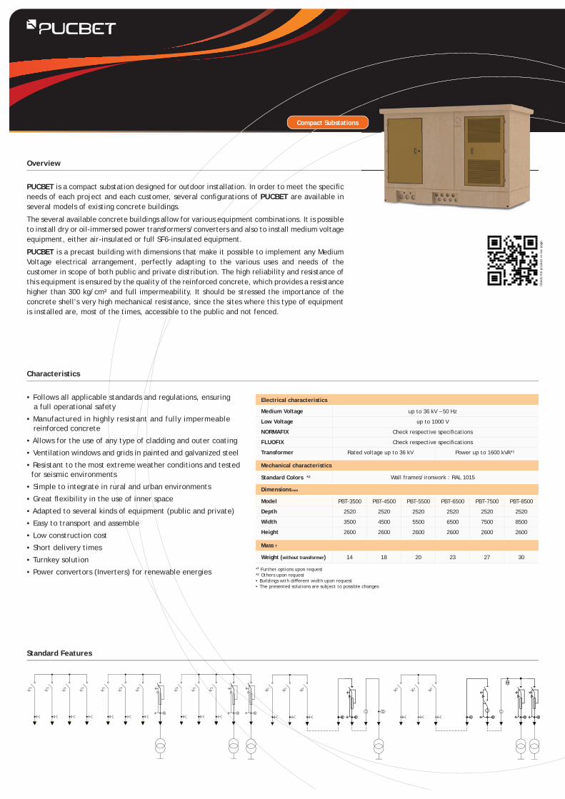
PUCBET is a compact substation designed for outdoor installation. In order to meet the specifi c needs of each project and each customer, several confi gurations of PUCBET are available in several models of existing concrete buildings.
The several available concrete buildings allow for various equipment combinations. It is possible to install dry or oil-immersed power transformers/converters and also to install medium voltage equipment, either air-insulated or full SF6-insulated equipment.
PUCBET is a precast building with dimensions that make it possible to implement any Medium Voltage electrical arrangement, perfectly adapting to the various uses and needs of the customer in scope of both public and private distribution. The high reliability and resistance of this equipment is ensured by the quality of the reinforced concrete, which provides a resistance higher than 300 kg/cm² and full impermeability. It should be stressed the importance of the concrete shell’s very high mechanical resistance, since the sites where this type of equipment is installed are, most of the times, accessible to the public and not fenced.
Overview
Characteristics
Standard Features
up to 36 kV – 50 Hz
up to 1000 V
Check respective specifi cations
Check respective specifi cations
Rated voltage up to 36 kV Power up to 1600 kVA*1
Dimensions mm
Mechanical characteristics
Electrical characteristics
Model
Depth
Width
Height
Weight (without transformer)
PBT-3500
2520
3500
2600
PBT-4500
2520
4500
2600
PBT-5500
2520
5500
2600
PBT-6500
2520
6500
2600
PBT-7500
2520
7500
2600
PBT-8500
2520
8500
2600
14 18 20 23 27 30
Medium Voltage
Low Voltage
NORMAFIX
FLUOFIX
Transformer
Standard Colors *² Wall frames/ironwork : RAL 1015
Mass T
• Certifi ed by KEMA
• Fully tested in the factory
• Completely manufactured in stainless steel (optionally in zincor)
• Resistant to extreme environments – protected against corrosion
• Special anti-condensation ventilation system
• Simple to integrate in rural and urban environments
• High fl exibility in the distribution of inner space
• Adapted to several types of equipment (public and private)
• Easy to transport (20 or 40-feet containers) and assemble
• Small installation area
• Low maintenance
• Anti-vandal protection
• Low construction cost
• Short delivery times
• Turnkey solution
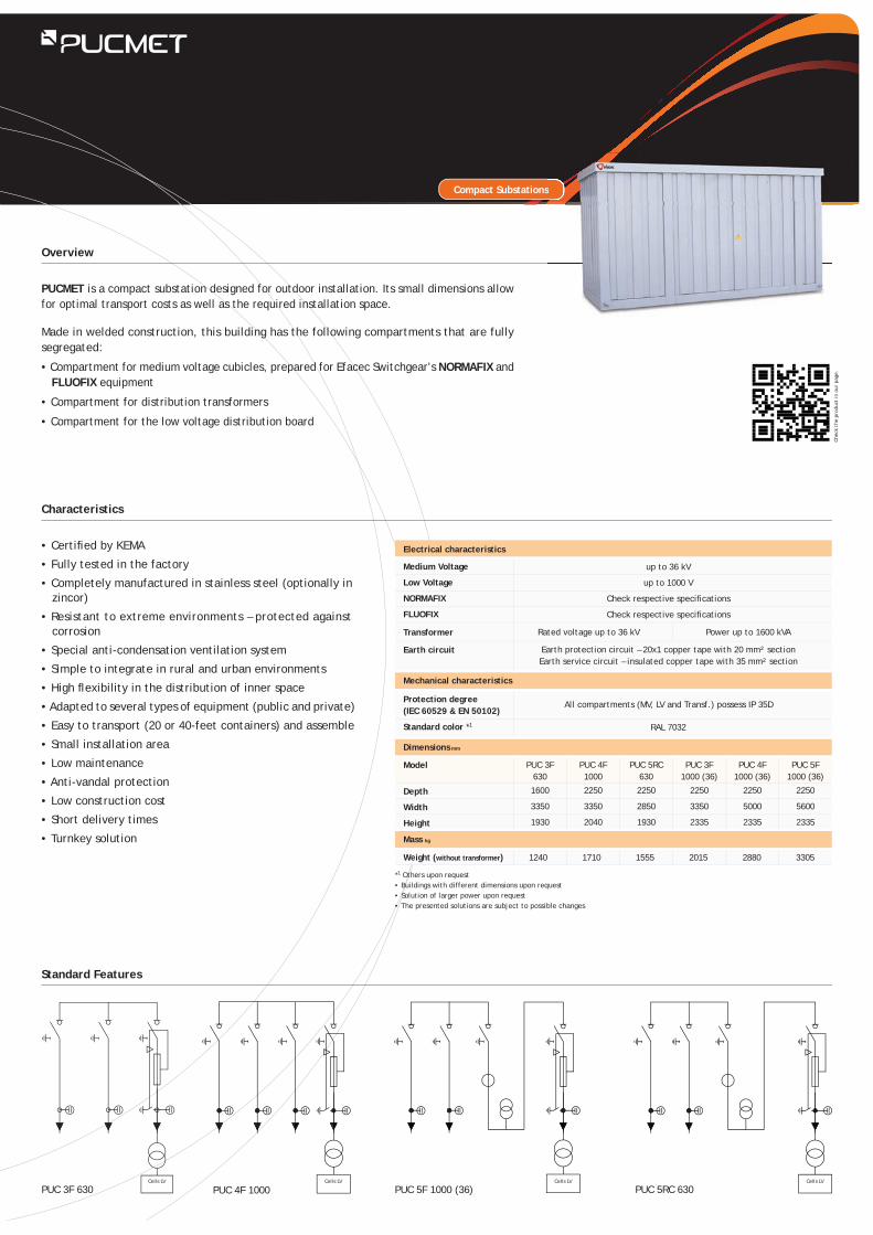
PUCMET is a compact substation designed for outdoor installation. Its small dimensions allow for optimal transport costs as well as the required installation space.
Made in welded construction, this building has the following compartments that are fully segregated:
• Compartment for medium voltage cubicles, prepared for Efacec Switchgear’s NORMAFIX and FLUOFIX equipment
• Compartment for distribution transformers
• Compartment for the low voltage distribution board
Overview
Characteristics
Standard Features
Compact Substations
PUC 3F 630 PUC 4F 1000 PUC 5F 1000 (36) PUC 5RC 630
*1 Others upon request• Buildings with different dimensions upon request• Solution of larger power upon request• The presented solutions are subject to possible changes
up to 36 kV
up to 1000 V
Check respective specifi cations
Check respective specifi cations
Rated voltage up to 36 kV Power up to 1600 kVA
Earth protection circuit – 20x1 copper tape with 20 mm² sectionEarth service circuit – insulated copper tape with 35 mm² section
Dimensions mm
Mechanical characteristics
Electrical characteristics
Model
Depth
Width
Height
Weight (without transformer)
PUC 3F 630
1600
3350
1930
PUC 4F 1000
2250
3350
2040
PUC 5RC 630
2250
2850
1930
PUC 3F 1000 (36)
2250
3350
2335
PUC 4F 1000 (36)
2250
5000
2335
PUC 5F 1000 (36)
2250
5600
2335
1240 1710 1555 2015 2880 3305
Medium Voltage
Low Voltage
NORMAFIX
FLUOFIX
Transformer
Earth circuit
Protection degree(IEC 60529 & EN 50102)
Standard color *1
All compartments (MV, LV and Transf.) possess IP 35D
RAL 7032
Mass kg
s
Chec
k th
e pr
oduc
t in
our
pag
e.
Cells LV Cells LV Cells LV Cells LV
Compact Substations
up to 24 kV
up to 1000 V
Check respective specifi cations
Power up to 1000 kVA
Medium Voltage | Low Voltage | Transformer
• Compact substation, standard up to 1000 kVA and voltages up to 24 kV
• Steel, 3CR12 stainless steel or other material according to the specifi cation of the Customer
• Small installation area
• Easy to transport and install
• Short delivery time
• Low maintenance
• Turnkey solution
• Flexibility of space distribution
• Option for installation of internal arc-proof means (chimney)
• Additional information
- Medium voltage compartment with an SF6-insulated unit of the FLUOFIX range
- Low Voltage switchgear in keeping with the customer’s specifi cations
Overview
Characteristics
Composition
Dimensions mm
Electrical characteristics
Medium Voltage
Low Voltage
FLUOFIX
Transformer
Compartments
Model
Depth
Width
Height
MSA
2800
1124
1425
MSA-c
2800
1124
1925
MSB
3000
1650
1465
MSB-c
3000
1650
1925
Note: Diff erent power upon request
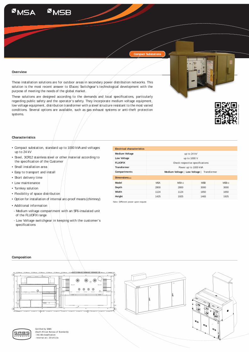
These installation solutions are for outdoor areas in secondary power distribution networks. This solution is the most recent answer to Efacec Switchgear’s technological development with the purpose of meeting the needs of the global market.
These solutions are designed according to the demands and local specifi cations, particularly regarding public safety and the operator’s safety. They incorporate medium voltage equipment, low voltage equipment, distribution transformer with a steel structure resistant to the most varied conditions. Several options are available, such as gas exhaust systems or anti-theft protection systems.
Chec
k th
e pr
oduc
t in
our
pag
e.
Certifi ed by SABS(South African Bureau of Standards)- IAC-AB classifi cation- Internal arc: 20 kA 0,5s
Compact Mobile Substations Compact Substations
• Emergency medium voltage supply system equipped with:
- Medium voltage solution up to 36 kV
- Generator up to 1250 kVA (standard)
- LV/MV step-up transformer, single voltage or double voltage
• Semitrailer (optional)
• Medium voltage cable winders (optional)
• MV metering equipment (optional)
• In keeping with all applicable standards and regulations, ensuring a full operational safety
• The container-type construction allows for easy transport (road, sea or railway)
• Ventilation adequate for the installed equipments
• Turnkey solution
• Possibility of customizing an exterior image according to the Customer’s specifi cations
Overview
Characteristics
Composition
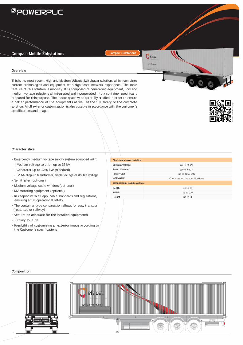
This is the most recent High and Medium Voltage Switchgear solution, which combines current technologies and equipment with signifi cant network experience. The main feature of this solution is mobility. It is composed of generating equipment, low and medium voltage solutions all integrated and incorporated into a container specifi cally prepared for this purpose. The indoor space w as carefully studied in order to ensure a better performance of the equipments as well as the full safety of the complete solution. A full exterior customization is also possible in accordance with the customer’s specifi cations and image.
Chec
k th
e pr
oduc
t in
our
pag
e.
up to 36 kV
up to 630 A
up to 1250 kVA
Check respective specifi cations
Dimensions m (mobile platform)
Electrical characteristics
Medium Voltage
Rated Current
Power Unit
NORMAFIX
Depth
Width
Height
up to 12
up to 2.5
up to 4
Solutions & Service
Overview
Commissioning
Maintenance After-Sales Service
Remodelling/ Rehabilitation
Efacec Switchgear has the expertise of more than 60 years developing, producing, installing, rehabilitating and maintaining Medium and High Voltage installations.
All technical means available leverage the capacity of Efacec Switchgear, associated to highly qualifi ed and specialized teams in this type of installations. Customers are provided with highly reliable and available systems resulting on economic profi ts and a more competitive business.
The aim of these intervention areas is to enhance the reliability, availability, durability, effi ciency and productivity of equipment and systems, assuring the protection and safety of people and reducing direct and indirect costs of maintenance and exploitation. The Efacec has the competence and experience required, running a quality service that adds value to their customers, opportunities for greater competitiveness to your business.
• Assembly of circuit-breakers, sectionalizers and HV draw-out units;• Tuning, tests and commissioning;• Assembly of medium voltage equipment;• Protection relays setting and testing;• Site acceptance tests and commissioning.
Efacec has the proprietary know-how of multiple Efacec and third party equipment and systems, covering a high level of technical areas and is entitled to supply a complete service, including total or part of overall maintenance contracts of medium and high voltage, at the power production centres, transport, distribution and industry.
The know-how and the experience of more than 60 years of fi eld activity enable us to play a leader role in domestic market and a reference in the international market, supplying a very qualifi ed service to our clients. We developed systems of power management and power effi ciency, focusing on how to use power by the clients, improving the quality and reducing costs.
High voltage• Reconditioning of HV circuit-breakers and sectionalizers;• Adapting/remodelling of High Voltage installations, with the replacement of:• Conductive parts of sectionalizers;• Old sectionalizer commands by up-to-date electrical commands;• Earth sectionnalizers;• Re-electrifi cation of the circuit-breaker commands;• Mobile parts of extractable parts with circuit-breakers and last generation transformers.
Medium voltage• Replacement of end-of-life circuit-breakers by today’s technology circuit-breakers (air cut,
DIVAC circuit-breaker) by adapting them to Efacec panels and others;• Development of adapting cells between diff erent cells;• Remodelling command and protection systems;• Deployment of safety systems using lock and/or padlock;• Installation of internal arc detection.
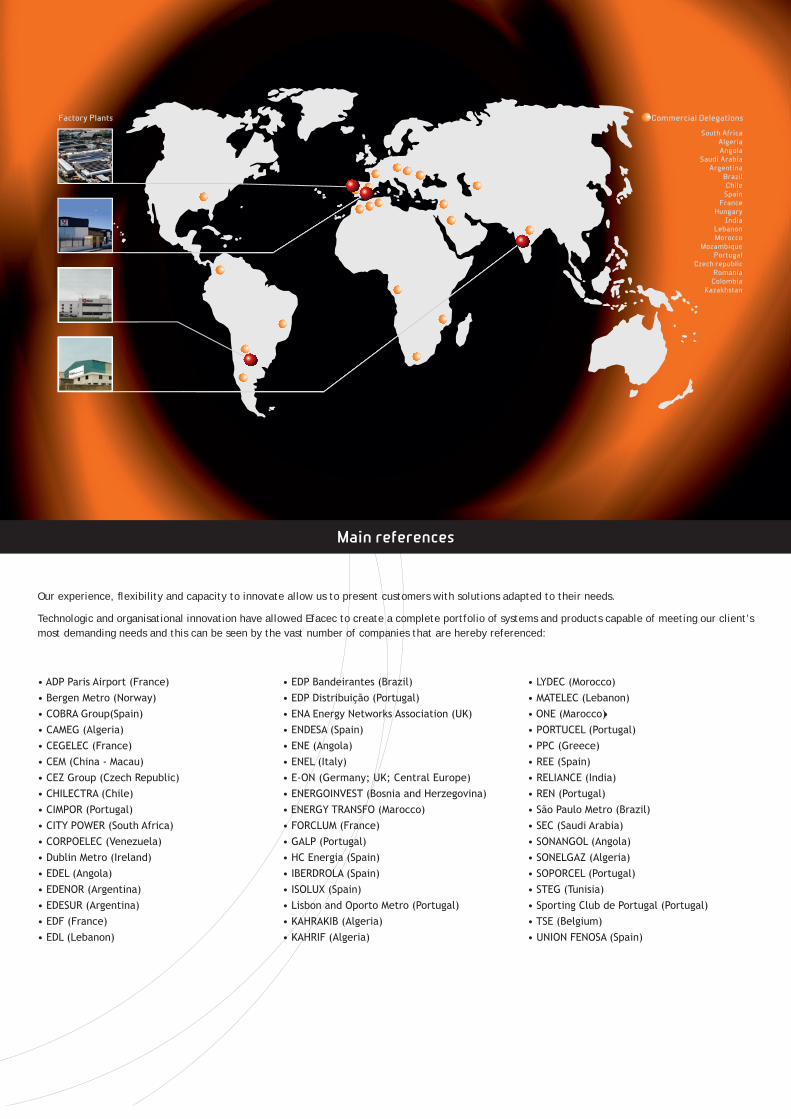
Commercial Delegations
South AfricaAlgeriaAngola
Saudi ArabiaArgentina
BrazilChile
SpainFrance
HungaryIndia
LebanonMorocco
MozambiquePortugal
Czech republicRomania
ColombiaKazakhstan
Factory Plants
Main references
Our experience, fl exibility and capacity to innovate allow us to present customers with solutions adapted to their needs.
Technologic and organisational innovation have allowed Efacec to create a complete portfolio of systems and products capable of meeting our client’s most demanding needs and this can be seen by the vast number of companies that are hereby referenced:
www.efacec.com
Headquarters
Efacec Energia, Máquinas e Equipamentos Eléctricos, S.A.
High and Medium Voltage Switchgear Unit
Apart. 10184466-952 S. Mamede de InfestaPortugal
Phone: + 351 229 562 300Fax: + 351 229 562 961
Email: [email protected]
NP 4 45 7
mod. CS243I1410B1
Due
to o
ur p
olic
y of
con
tinu
ous
deve
lopm
ent,
spe
cifi
cati
ons
may
cha
nge
whi
thou
t no
tice
. N
ot v
alid
as
a co
ntra
ctua
l ite
m.