Embed Size (px)
Citation preview
High average current electron guns for high-power free electron lasers
Phillip Sprangle, Joseph Penano, Bahman Hafizi,* Daniel Gordon, Steven Gold, Antonio Ting, and Chad Mitchell
Plasma Physics Division, Naval Research Laboratory, Washington, D.C. 20375, USA(Received 14 June 2010; published 14 February 2011)
High average power free-electron lasers (FELs) require high average current electron injectors capable
of generating high quality, short duration electron bunches with a repetition rate equal to the frequency of
the rf linac. In this paper we propose, analyze, and simulate an rf-gated, gridded thermionic electron gun
for use in high average power FELs. Thermionic cathodes can provide the necessary high current, have
long lifetimes, and require modest vacuums. In the proposed configuration the rf-gated grid is modulated
at the fundamental and 3rd harmonic of the linac frequency. The addition of the 3rd harmonic on the grid
results in shorter electron bunches. In this configuration, every rf bucket of the linac accelerating field
contains an electron bunch. Particle-in-cell simulations indicate that this approach can provide the
necessary charge per bunch, bunch duration, longitudinal and transverse emittance, and repetition rate
for high average power FELs operating in the IR regime.
DOI: 10.1103/PhysRevSTAB.14.020702 PACS numbers: 41.60.Cr, 07.77.Ka
I. INTRODUCTION
High average power free-electron lasers (FELs) [1–9]require a train of short duration, high repetition rate, andhigh peak current electron bunches having high quality andhigh average current [1]. These requirements place strin-gent constraints on the electron gun [2–4].
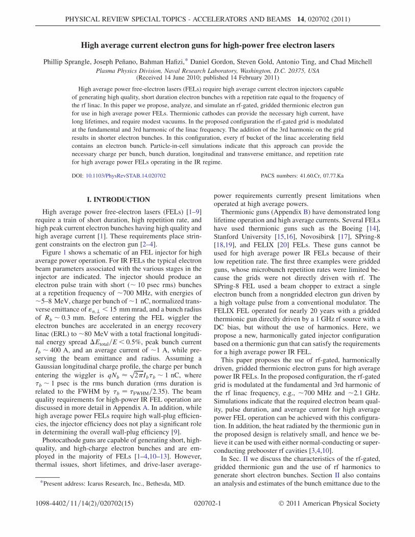
Figure 1 shows a schematic of an FEL injector for highaverage power operation. For IR FELs the typical electronbeam parameters associated with the various stages in theinjector are indicated. The injector should produce anelectron pulse train with short (� 10 psec rms) bunchesat a repetition frequency of �700 MHz, with energies of�5–8 MeV, charge per bunch of�1 nC, normalized trans-verse emittance of "n;? < 15 mmmrad, and a bunch radiusof Rb � 0:3 mm. Before entering the FEL wiggler theelectron bunches are accelerated in an energy recoverylinac (ERL) to �80 MeV with a total fractional longitudi-nal energy spread �Etotal=E < 0:5%, peak bunch currentIb � 400 A, and an average current of �1 A, while pre-serving the beam emittance and radius. Assuming aGaussian longitudinal charge profile, the charge per bunch
entering the wiggler is qNb �ffiffiffiffiffiffiffi2�
pIb�b � 1 nC, where
�b � 1 psec is the rms bunch duration (rms duration isrelated to the FWHM by �b ¼ �FWHM=2:35). The beamquality requirements for high-power IR FEL operation arediscussed in more detail in Appendix A. In addition, whilehigh average power FELs require high wall-plug efficien-cies, the injector efficiency does not play a significant rolein determining the overall wall-plug efficiency [9].
Photocathode guns are capable of generating short, high-quality, and high-charge electron bunches and are em-ployed in the majority of FELs [1–4,10–13]. However,thermal issues, short lifetimes, and drive-laser average-
power requirements currently present limitations whenoperated at high average powers.Thermionic guns (Appendix B) have demonstrated long
lifetime operation and high average currents. Several FELshave used thermionic guns such as the Boeing [14],Stanford University [15,16], Novosibirsk [17], SPring-8[18,19], and FELIX [20] FELs. These guns cannot beused for high average power IR FELs because of theirlow repetition rate. The first three examples were griddedguns, whose microbunch repetition rates were limited be-cause the grids were not directly driven with rf. TheSPring-8 FEL used a beam chopper to extract a singleelectron bunch from a nongridded electron gun driven bya high voltage pulse from a conventional modulator. TheFELIX FEL operated for nearly 20 years with a griddedthermionic gun directly driven by a 1 GHz rf source with aDC bias, but without the use of harmonics. Here, wepropose a new, harmonically gated injector configurationbased on a thermionic gun that can satisfy the requirementsfor a high average power IR FEL.This paper proposes the use of rf-gated, harmonically
driven, gridded thermionic electron guns for high averagepower IR FELs. In the proposed configuration, the rf-gatedgrid is modulated at the fundamental and 3rd harmonic ofthe rf linac frequency, e.g., �700 MHz and �2:1 GHz.Simulations indicate that the required electron beam qual-ity, pulse duration, and average current for high averagepower FEL operation can be achieved with this configura-tion. In addition, the heat radiated by the thermionic gun inthe proposed design is relatively small, and hence we be-lieve it can be used with either normal-conducting or super-conducting prebooster rf cavities [3,4,10].In Sec. II we discuss the characteristics of the rf-gated,
gridded thermionic gun and the use of rf harmonics togenerate short electron bunches. Section II also containsan analysis and estimates of the bunch emittance due to the*Present address: Icarus Research, Inc., Bethesda, MD.
PHYSICAL REVIEW SPECIAL TOPICS - ACCELERATORS AND BEAMS 14, 020702 (2011)
1098-4402=11=14(2)=020702(15) 020702-1 � 2011 American Physical Society
grid. Section III presents the results of particle-in-cell(PIC) simulations of thermionic injector operation usingthe TURBOWAVE [21] and PARMELA [22] codes. Section IVsummarizes our theoretical and numerical results. A fullyfunctioning prototype may require that the bunch emit-tance be lowered by reshaping the cathode and anode.Appendices A, B, and C present additional details of thethermionic gun.
II. RF-GATED, GRIDDED THERMIONIC GUN
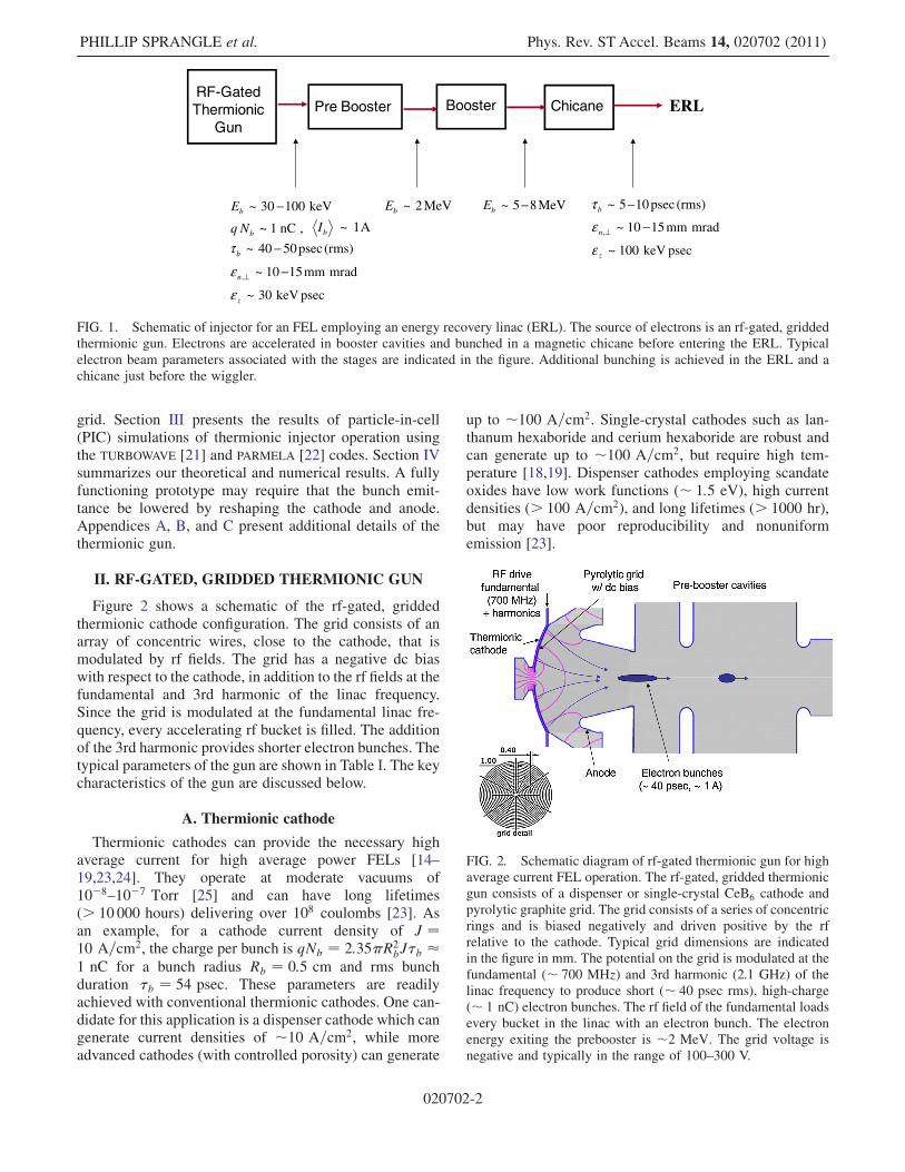
Figure 2 shows a schematic of the rf-gated, griddedthermionic cathode configuration. The grid consists of anarray of concentric wires, close to the cathode, that ismodulated by rf fields. The grid has a negative dc biaswith respect to the cathode, in addition to the rf fields at thefundamental and 3rd harmonic of the linac frequency.Since the grid is modulated at the fundamental linac fre-quency, every accelerating rf bucket is filled. The additionof the 3rd harmonic provides shorter electron bunches. Thetypical parameters of the gun are shown in Table I. The keycharacteristics of the gun are discussed below.
A. Thermionic cathode
Thermionic cathodes can provide the necessary highaverage current for high average power FELs [14–19,23,24]. They operate at moderate vacuums of10�8–10�7 Torr [25] and can have long lifetimes(> 10 000 hours) delivering over 108 coulombs [23]. Asan example, for a cathode current density of J ¼10 A=cm2, the charge per bunch is qNb ¼ 2:35�R2
bJ�b �1 nC for a bunch radius Rb ¼ 0:5 cm and rms bunchduration �b ¼ 54 psec. These parameters are readilyachieved with conventional thermionic cathodes. One can-didate for this application is a dispenser cathode which cangenerate current densities of �10 A=cm2, while moreadvanced cathodes (with controlled porosity) can generate
up to �100 A=cm2. Single-crystal cathodes such as lan-thanum hexaboride and cerium hexaboride are robust andcan generate up to �100 A=cm2, but require high tem-perature [18,19]. Dispenser cathodes employing scandateoxides have low work functions (� 1:5 eV), high currentdensities (> 100 A=cm2), and long lifetimes (> 1000 hr),but may have poor reproducibility and nonuniformemission [23].
FIG. 2. Schematic diagram of rf-gated thermionic gun for highaverage current FEL operation. The rf-gated, gridded thermionicgun consists of a dispenser or single-crystal CeB6 cathode andpyrolytic graphite grid. The grid consists of a series of concentricrings and is biased negatively and driven positive by the rfrelative to the cathode. Typical grid dimensions are indicatedin the figure in mm. The potential on the grid is modulated at thefundamental (� 700 MHz) and 3rd harmonic (2.1 GHz) of thelinac frequency to produce short (� 40 psec rms), high-charge(� 1 nC) electron bunches. The rf field of the fundamental loadsevery bucket in the linac with an electron bunch. The electronenergy exiting the prebooster is �2 MeV. The grid voltage isnegative and typically in the range of 100–300 V.
MeV85~ −bE
pseckeV100~zε
mradmm1510~, −⊥nε(rms)psec105~ −bτMeV2~bE
Booster ChicanePre BoosterRF-Gated Thermionic
GunERL
,nC1~bNq A1~bI
(rms)psec5040~ −bτ
mradmm1510~, −⊥nεpseckeV30~zε
keV10030~ −bE
FIG. 1. Schematic of injector for an FEL employing an energy recovery linac (ERL). The source of electrons is an rf-gated, griddedthermionic gun. Electrons are accelerated in booster cavities and bunched in a magnetic chicane before entering the ERL. Typicalelectron beam parameters associated with the stages are indicated in the figure. Additional bunching is achieved in the ERL and achicane just before the wiggler.
PHILLIP SPRANGLE et al. Phys. Rev. ST Accel. Beams 14, 020702 (2011)
020702-2

The current-voltage characteristics of thermionic cath-odes are determined by the material, temperature as wellas the external and space-charge fields. In the steady-state, 1D limit, the space-charge limited current densityis given by the Child-Langmuir (CL) relationship [23,26–
28], JCL½A=cm2� ¼ 2:33� 10�6�3=2½V�=d2½cm�, where� � 0 is the voltage difference between the two conduct-ing planes and d is the separation.
In the temperature-limited regime, i.e., the Richardson-Dushman-Schottky (RDS) limit, the current density isgiven by [29,30]: JRDS½A=cm2�¼AoT
2c expf�11605�WF=
Tcgexpf4:4ð�½V�=d½cm�Þ1=2=Tcg, where Ao ¼ 120 A=ðcm2 K2Þ, �WF is the work function (eV) of the cathodeand Tc is the temperature (K). The above value for Ao is thetheoretically derived value while the experimentally mea-sured value for CeB6 indicates that Ao � 20A=ðcm2 K2Þ[18].
The Child-Langmuir and the Richardson-Dushman-Schottky regimes are plotted in Fig. 3 for d ¼ 250 �m,�WF ¼ 1:9 eV, Tc ¼ 1300 K, and Ao ¼ 120 A=ðcm2 K2Þ.The optimum operating regime for the rf-gated gun is nearthe intersection of the space-charge and thermal limitswhere the current density is not sensitive to fluctuationsin the cathode temperature as shown in Fig. 3.There is a third emission regime in which a high surface
electric field ES � 107–108 V=cm is employed to extractelectrons by tunneling. This field emission regime isparticularly effective when the cathode consists of sharptips. In this regime the current density is given by the
Fowler-Nordheim (FN) relation [23,31], JFN½A=cm2� ¼AFNE
2S expð�BFN=ES þ 9:8=
ffiffiffiffiffiffiffiffiffiffi�WF
p Þ, where AFN½A=V2� �1:4� 10�6=�WF, BFN½V=cm� � 6:5� 107�3=2
WF, and ES isin units of V=cm. Field emitting cathodes are also beingconsidered for high average current guns for FELs [32].
B. rf-gated grid
The actual grid configuration consists of a series ofconcentric rings and radial spokes located close to thecathode surface as shown in Fig. 2. However, for thepurpose of the following analysis, the rings are modeledby an array of parallel wires as shown in Fig. 4 and the rfmodulation is treated electrostatically.The potential on the grid wires is �G, the potential
difference between the cathode and anode is �A. Thegrid wires are parallel to the y axis, separated by a distance2a and located at z ¼ zG. The radius of the grid wires istaken to be small, ro � a; zG. The potential in the cathode-grid-anode region is given by (Appendix C)
�ðx; zÞ ¼ � Xn¼�1;�3;
��O ln
Gnðx; zÞFnðx; zÞ þ�A
r2oðz� zGÞ=zAGnðx; zÞ
�
þ�A
z
zA; (1)
where �O¼ð1=2Þð�G��AzG=zAÞ½lnð2zG=roÞþMo��1,Fnðx; zÞ ¼ ðx� naÞ2 þ ðzþ zGÞ2, Gnðx; zÞ ¼ ðx� naÞ2þðz� zGÞ2, Mo ¼
P1l¼1;2;3; ln½1þ z2G=ð‘2a2Þ�, and the sum
FIG. 3. Current density-voltage characteristics, J vs �. Thesolid curve is the space-charge limit (Child-Langmuir) and thedashed curve is the thermal limit (Richardson-Dushman-Schottky). The characteristics are for the case with gap spacingd ¼ 250 �m, work function �WF ¼ 1:9 eV, and cathode tem-perature Tc ¼ 1300 K. The optimum operating region is near theintersection of the two limits where the current density is not asensitive function of the cathode temperature.
a2
zGz
x
y
gridcathode
Az
anode
AΦ0=ΦC
)(tGΦ
x
y
grid
a2
)(tGΦ
or2or2
a2
zGz
x
y
gridcathode
Az
anode
AΦ0=ΦC
)(tGΦ
x
y
grid
a2
)(tGΦ
or2or2
FIG. 4. Schematic of grid wires used for obtaining an estimateof the beam emittance due to the grid. The rings comprising thegrid in Fig. 2 are modeled by an array of parallel grid wires. Thegrid wires, with radius ro, are at a potential �G, are parallel tothe y axis, separated by a distance 2a, and located at z ¼ zG.
TABLE I. Typical range of parameters in an rf-gated, griddedthermionic gun in which a conventional dispenser cathode isemployed.
Cathode-grid gap, zG 250 �mCathode-anode gap, zA 1–3 cm
Grid wire radius, ro 30 �mGrid wire separation, 2a 400–500 �mCathode radius, Rc 0.5–1.5 cm
Cathode-grid voltage, �G 100–300 V
Cathode-anode voltage, �A 30–50 kV
rf grid modulation frequency, frf 500 MHz–2.5 GHz
Cathode current density, J 10–15 A=cm2
Cathode temperature, Tc 1200–1400 K
Cathode work function, �WF 1.6–2.1 eV
Vacuum level 10�7–10�8 Torr
HIGH AVERAGE CURRENT ELECTRON GUNS FOR HIGH- . . . Phys. Rev. ST Accel. Beams 14, 020702 (2011)
020702-3
is over the grid wires. The first term in the sum representsthe potential due to the grid wires and their images from thecathode. The second term is a contribution induced by theelectric field between the anode and cathode and is local-ized to the region around the wires. The last term in Eq. (1)represents the cathode-anode gap potential. The potentialsatisfies the appropriate boundary conditions on the cath-ode, grid, and anode surfaces.
The grid potential is the sum of a constant (dc) and atime varying (rf) contribution, i.e.,�GðtÞ ¼ �DC þ�rfðtÞ.The rf grid potential is given by �rfðtÞ ¼ �1 cosð!rftþ’1Þ þ�3 cosð3!rftþ ’3Þ, where !rf is the fundamentallinac frequency, �‘ is the amplitude of the ‘th harmonic,’‘ is a constant phase, and ‘ ¼ 1 or 3. For parameters ofinterest the electrostatic approximation is valid, in theabsence of beam loading effects, since the electron transittime �transit � zG=vz � 30 psec between the cathode andgrid is small compared to the rf period, �rf ¼ 2�=!rf �1:4 nsec.
Figure 5 illustrates the grid potential modulation that canbe achieved using dc bias, fundamental, and 3rd harmonic.The figure schematically indicates the generation of shortelectron bunches of �100 psec (rms) duration can beobtained at a repetition rate of 700 MHz. Shorter bunchescan be achieved by the addition of higher harmonics, e.g.,5th harmonic at 3.5 GHz.
Electron emission takes place when the axial electricfield on the cathode surface is negative. The axial field onthe cathode (in the absence of space-charge), from Eq. (C5)in Appendix C, is
Ezðx; z ¼ 0Þ ¼ ��A=zA ��ðxÞð�G=zG ��A=zAÞ; (2)
where 0<�ðxÞ< 1 is a shielding parameter defined inEq. (C6). The shielding parameter represents the reductionof the anode field due to the presence of the grid wires. Theshielding of the electric field on the cathode is minimum
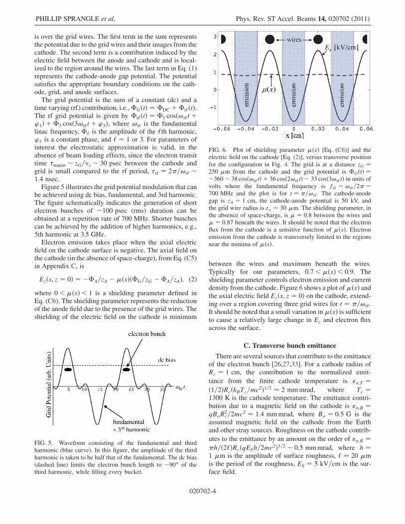
between the wires and maximum beneath the wires.Typically for our parameters, 0:7<�ðxÞ< 0:9. Theshielding parameter controls electron emission and currentdensity from the cathode. Figure 6 shows a plot of�ðxÞ andthe axial electric field Ezðx; z ¼ 0Þ on the cathode, extend-ing over a region covering three grid wires for t ¼ �=!rf .It should be noted that a small variation in�ðxÞ is sufficientto cause a relatively large change in Ez and electron fluxacross the surface.
C. Transverse bunch emittance
There are several sources that contribute to the emittanceof the electron bunch [26,27,33]. For a cathode radius ofRc ¼ 1 cm, the contribution to the normalized emit-
tance from the finite cathode temperature is "n;T ¼ð1=2ÞRcðkBTc=mc2Þ1=2 � 2 mmmrad, where Tc ¼1300 K is the cathode temperature. The emittance contri-bution due to a magnetic field on the cathode is "n;B ¼qBoR
2c=2mc2 � 1:4 mmmrad, where Bo ¼ 0:5 G is the
assumed magnetic field on the cathode from the Earthand other stray sources. Roughness on the cathode contrib-
utes to the emittance by an amount on the order of "n;R ¼�h=ð2‘ÞRcðqESh=2mc2Þ1=2 � 0:5 mmmrad, where h ¼1 �m is the amplitude of surface roughness, ‘ ¼ 20 �mis the period of the roughness, ES ¼ 5 kV=cm is the sur-face field.
FIG. 5. Waveform consisting of the fundamental and thirdharmonic (blue curve). In this figure, the amplitude of the thirdharmonic is taken to be half that of the fundamental. The dc bias(dashed line) limits the electron bunch length to �90 of thethird harmonic, while filling every bucket.
FIG. 6. Plot of shielding parameter �ðxÞ [Eq. (C6)] and theelectric field on the cathode [Eq. (2)], versus transverse positionfor the configuration in Fig. 4. The grid is at a distance zG ¼250 �m from the cathode and the grid potential is �GðtÞ ¼�360� 38 cosð!rftÞ þ 36 cosð2!rftÞ � 33 cosð3!rftÞ in units ofvolts where the fundamental frequency is frf ¼ !rf=2� ¼700 MHz and the plot is for t ¼ �=!rf . The cathode-anodegap is zA ¼ 1 cm, the cathode-anode potential is 50 kV, andthe grid wire radius is ro ¼ 30 �m. The shielding parameter, inthe absence of space-charge, is � ¼ 0:8 between the wires and� ¼ 0:87 beneath the wires. It should be noted that the electronflux from the cathode is a sensitive function of �ðxÞ. Electronemission from the cathode is transversely limited to the regionsnear the minima of �ðxÞ.
PHILLIP SPRANGLE et al. Phys. Rev. ST Accel. Beams 14, 020702 (2011)
020702-4
The emittance due to a single grid wire, as shown inFig. 7, in the absence of self-fields, is given by(Appendix C)
"n;grid � Rbh�xi � 2�1ðaÞ3
�a
zG
�Rb
j ��G � ðzG=zAÞ ��AjðzG=zAÞ1=2 ��1=2
A
;
(3)
where Rb � Rc is the beam radius, h�xi is the averagednormalized electron velocity, �1ðaÞ is the shielding
parameter due to one wire (Appendix C), ��G ¼jqj�G=ðmc2Þ, and ��A ¼ jqj�A=ðmc2Þ. Using typical val-ues for the gun parameters, the normalized emittance dueto the grid is "n;grid½mmmrad� � 5–10Rb½cm�. This rangeof emittances is consistent with PIC simulation results thatare presented in the next section.
The nonrandom, macroscopic contributions to the beamemittance, e.g., due to focusing/accelerating fields andspace-charge fields, can be reduced through the use ofemittance compensating coils or optimizing the anodegeometry. The microscopic and random contributions toemittance, e.g., cathode temperature, cathode surfaceroughness, grid fields, or slice emittance, cannot be re-duced using emittance compensating coils. From PARMELA
simulations, it is known that the dominant contribution tothe transverse emittance is the nonlaminar flow induced bythe cathode/anode geometry, and the grid fields. Additionalwork is under way to understand the various contributionsto the emittance and to reduce emittance growth due tospace-charge and macroscopic nonlinear effects by chang-ing the gun geometry and the use of emittance compensa-tion coils [34].
III. PIC SIMULATIONS
Accurate numerical simulation of the injector requiresthe modeling of complicated geometries and numerousphysical processes, not all of which are contained in anysingle code. For example, TURBOWAVE [21] can modelfully electromagnetic particle fields and image charges
induced on the cathode, anode, and grid wires, but isdifficult to use with the complicated geometry of a realisticcathode-grid design. PARMELA [22] on the other hand, canhandle more complicated geometries, but does not calcu-late image fields correctly, i.e., the image fields due to thegrid and anode are neglected. In this section, we present anumber of simulations using both TURBOWAVE andPARMELA to illustrate the basic operation of a thermionic
injector for a high-power FEL. The injector geometry isbased on an inductive output tube (IOT) gun design [35]and the basic parameters used in the PARMELA simulationsare listed in Table II. Because of the different geometriesused in the TURBOWAVE (2D axisymmetric, planar cathodeand grid) and PARMELA simulations (2D axisymmetric,curved cathode and grid), the parameters used differ be-tween the two codes. The PARMELA injector simulation thatuses a filled cathode (see Fig. 19) produces electronbunches with characteristics required for high-power FELoperation, as specified in Fig. 1. However, this simulationshould serve only as a basic illustration of high-powerinjector operation and not an actual injector design. Aninjector design would require further optimization of thecathode, grid, and anode geometry.
A. TURBOWAVE
TURBOWAVE is a 2D or 3D, fully relativistic PIC code
that models a variety of physical processes. Here we de-scribe two-dimensional slab and axially symmetric electro-static simulations of the gun. In these simulations thecathode and anode are held at fixed potentials, while thegrid consists of parallel wires or concentric rings whosepotential is a prescribed function of time. The potential atall other locations within the gun region is computed viasuccessive over-relaxation, and includes space-chargeeffects.
TABLE II. Parameters used for PARMELA simulation of an rf-gated, gridded thermionic gun for a high-average-power FEL.The gun geometry is shown in Fig. 19. Bunch diagnostics areprovided at the gun exit at z ¼ 5:0.
Cathode-grid gap, zG 250 �mCathode-anode gap, zA 1.4 cm
Grid wire radius, ro 30 �mGrid wire separation, 2a 450 �mCathode radius, Rc 1.5 cm (0.9 cm active)
Peak cathode field, jEzjmax 6:5 kV=cmCathode-anode voltage, �A 35 kV
rf grid modulation frequency, frf 700 MHz, 2.1 GHz
Bunch charge, qNb 1 nC
Average energy, E 35 kV
Energy spread (rms) 1%
Pulse length (rms), �b 45 psec
Transverse emittance (rms), "n;x 16 mmmrad
Longitudinal emittance (rms), "z 7 keV psec
z
Gz
x
grid wire,
cathode 0=Φ C
θ∆
0xx =
GΦ
or2
FIG. 7. Calculation of emittance due to a single grid wire. Herethe cathode is at ground potential and located at z ¼ 0, the gridwire is at potential �G, located at z ¼ zG, and has radius ro. Anelectron with impact parameter x0 is deflected through an angle�� due to grid wire.
HIGH AVERAGE CURRENT ELECTRON GUNS FOR HIGH- . . . Phys. Rev. ST Accel. Beams 14, 020702 (2011)
020702-5
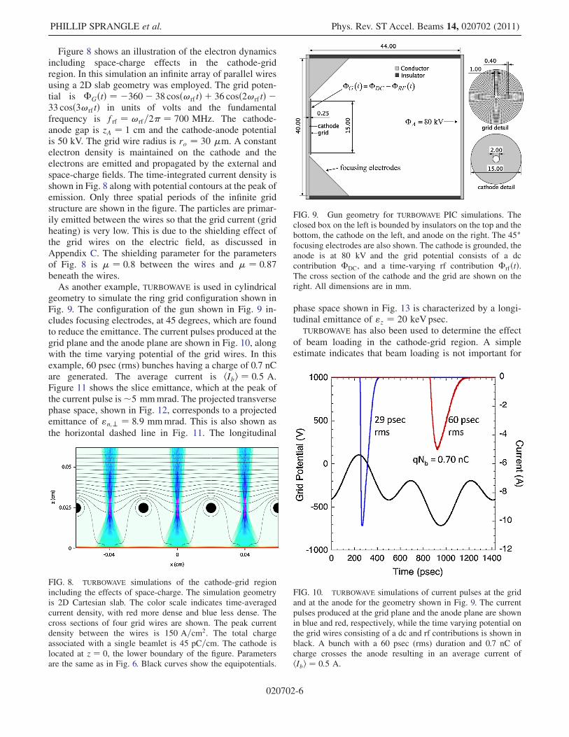
Figure 8 shows an illustration of the electron dynamicsincluding space-charge effects in the cathode-gridregion. In this simulation an infinite array of parallel wiresusing a 2D slab geometry was employed. The grid poten-tial is �GðtÞ ¼ �360� 38 cosð!rftÞ þ 36 cosð2!rftÞ �33 cosð3!rftÞ in units of volts and the fundamentalfrequency is frf ¼ !rf=2� ¼ 700 MHz. The cathode-anode gap is zA ¼ 1 cm and the cathode-anode potentialis 50 kV. The grid wire radius is ro ¼ 30 �m. A constantelectron density is maintained on the cathode and theelectrons are emitted and propagated by the external andspace-charge fields. The time-integrated current density isshown in Fig. 8 along with potential contours at the peak ofemission. Only three spatial periods of the infinite gridstructure are shown in the figure. The particles are primar-ily emitted between the wires so that the grid current (gridheating) is very low. This is due to the shielding effect ofthe grid wires on the electric field, as discussed inAppendix C. The shielding parameter for the parametersof Fig. 8 is � ¼ 0:8 between the wires and � ¼ 0:87beneath the wires.
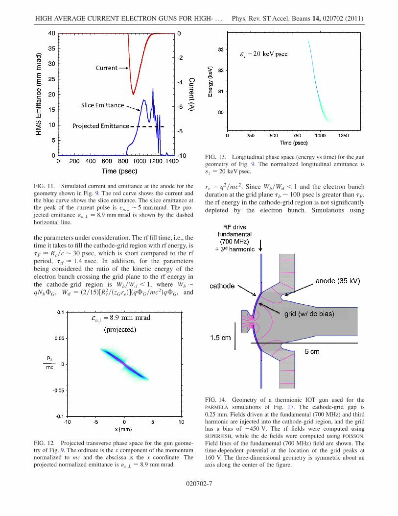
As another example, TURBOWAVE is used in cylindricalgeometry to simulate the ring grid configuration shown inFig. 9. The configuration of the gun shown in Fig. 9 in-cludes focusing electrodes, at 45 degrees, which are foundto reduce the emittance. The current pulses produced at thegrid plane and the anode plane are shown in Fig. 10, alongwith the time varying potential of the grid wires. In thisexample, 60 psec (rms) bunches having a charge of 0.7 nCare generated. The average current is hIbi ¼ 0:5 A.Figure 11 shows the slice emittance, which at the peak ofthe current pulse is�5 mmmrad. The projected transversephase space, shown in Fig. 12, corresponds to a projectedemittance of "n;? ¼ 8:9 mmmrad. This is also shown as
the horizontal dashed line in Fig. 11. The longitudinal
phase space shown in Fig. 13 is characterized by a longi-tudinal emittance of "z ¼ 20 keV psec.
TURBOWAVE has also been used to determine the effect
of beam loading in the cathode-grid region. A simpleestimate indicates that beam loading is not important for
FIG. 8. TURBOWAVE simulations of the cathode-grid regionincluding the effects of space-charge. The simulation geometryis 2D Cartesian slab. The color scale indicates time-averagedcurrent density, with red more dense and blue less dense. Thecross sections of four grid wires are shown. The peak currentdensity between the wires is 150 A=cm2. The total chargeassociated with a single beamlet is 45 pC=cm. The cathode islocated at z ¼ 0, the lower boundary of the figure. Parametersare the same as in Fig. 6. Black curves show the equipotentials.
FIG. 9. Gun geometry for TURBOWAVE PIC simulations. Theclosed box on the left is bounded by insulators on the top and thebottom, the cathode on the left, and anode on the right. The 45focusing electrodes are also shown. The cathode is grounded, theanode is at 80 kV and the grid potential consists of a dccontribution �DC, and a time-varying rf contribution �rfðtÞ.The cross section of the cathode and the grid are shown on theright. All dimensions are in mm.
FIG. 10. TURBOWAVE simulations of current pulses at the gridand at the anode for the geometry shown in Fig. 9. The currentpulses produced at the grid plane and the anode plane are shownin blue and red, respectively, while the time varying potential onthe grid wires consisting of a dc and rf contributions is shown inblack. A bunch with a 60 psec (rms) duration and 0.7 nC ofcharge crosses the anode resulting in an average current ofhIbi ¼ 0:5 A.
PHILLIP SPRANGLE et al. Phys. Rev. ST Accel. Beams 14, 020702 (2011)
020702-6
the parameters under consideration. The rf fill time, i.e., thetime it takes to fill the cathode-grid region with rf energy, is�F � Rc=c� 30 psec, which is short compared to the rfperiod, �rf � 1:4 nsec. In addition, for the parametersbeing considered the ratio of the kinetic energy of theelectron bunch crossing the grid plane to the rf energy inthe cathode-grid region is Wb=Wrf < 1, where Wb �qNb�G, Wrf ¼ ð2=15Þ½R2
c=ðzGreÞ�ðq�G=mc2Þq�G, and
re ¼ q2=mc2. Since Wb=Wrf < 1 and the electron bunchduration at the grid plane �b � 100 psec is greater than �F,the rf energy in the cathode-grid region is not significantlydepleted by the electron bunch. Simulations using
FIG. 11. Simulated current and emittance at the anode for thegeometry shown in Fig. 9. The red curve shows the current andthe blue curve shows the slice emittance. The slice emittance atthe peak of the current pulse is "n;? � 5 mmmrad. The pro-
jected emittance "n;? ¼ 8:9 mmmrad is shown by the dashed
horizontal line.
FIG. 12. Projected transverse phase space for the gun geome-try of Fig. 9. The ordinate is the x component of the momentumnormalized to mc and the abscissa is the x coordinate. Theprojected normalized emittance is "n;? ¼ 8:9 mmmrad.
FIG. 13. Longitudinal phase space (energy vs time) for the gungeometry of Fig. 9. The normalized longitudinal emittance is"z ¼ 20 keV psec.
FIG. 14. Geometry of a thermionic IOT gun used for thePARMELA simulations of Fig. 17. The cathode-grid gap is
0.25 mm. Fields driven at the fundamental (700 MHz) and thirdharmonic are injected into the cathode-grid region, and the gridhas a bias of �450 V. The rf fields were computed usingSUPERFISH, while the dc fields were computed using POISSON.
Field lines of the fundamental (700 MHz) field are shown. Thetime-dependent potential at the location of the grid peaks at160 V. The three-dimensional geometry is symmetric about anaxis along the center of the figure.
HIGH AVERAGE CURRENT ELECTRON GUNS FOR HIGH- . . . Phys. Rev. ST Accel. Beams 14, 020702 (2011)
020702-7
TURBOWAVE are consistent with the above arguments that
beam loading for the parameters under consideration is notsignificant.
B. PARMELA
IOT guns have a number of characteristics necessaryfor use as injectors for high-power FELs, e.g., high aver-age currents, short bunch lengths, long lifetimes, robust-ness, etc. However, because the applications for whichIOT guns were designed did not require low emittance,the transverse bunch emittance is typically too large foruse as a high average power FEL injector. In this sub-section, we use the PARMELA code to simulate the com-plicated geometry and field structures of two typical IOTgun designs and characterize the emitted electronbunches. We show that, through the use of fundamentaland third harmonic rf frequencies, the bunch length issufficiently short and the average current sufficiently highfor use as a high-power FEL injector. While the resultingemittance is large (15–25 mmmrad), it should be possibleto modify the present gun design to lower the emittance,for example, by improving the anode and cathodegeometry.
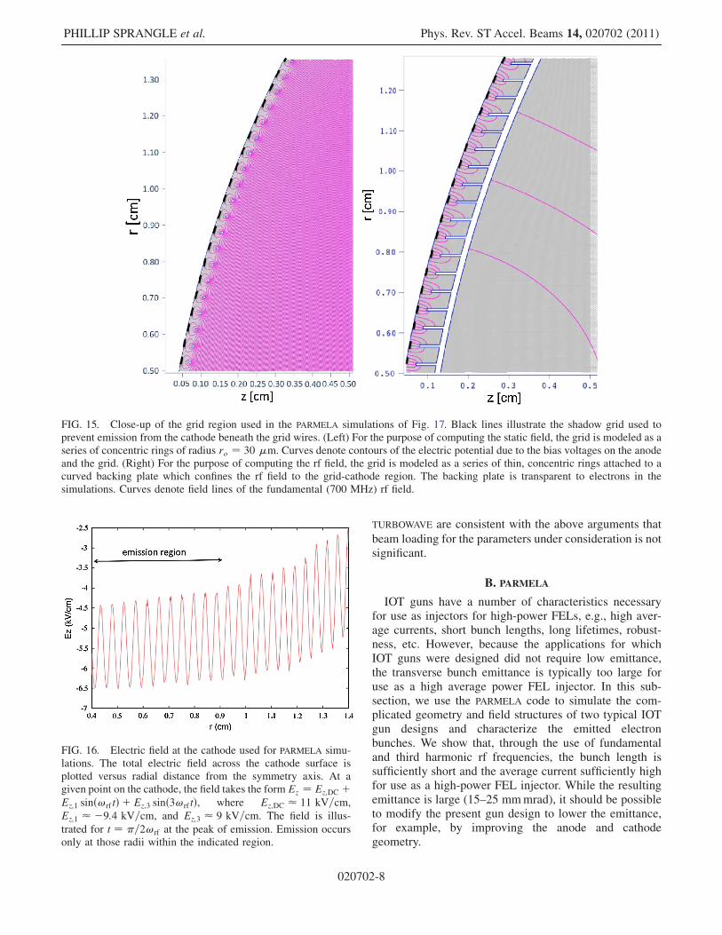
FIG. 15. Close-up of the grid region used in the PARMELA simulations of Fig. 17. Black lines illustrate the shadow grid used toprevent emission from the cathode beneath the grid wires. (Left) For the purpose of computing the static field, the grid is modeled as aseries of concentric rings of radius ro ¼ 30 �m. Curves denote contours of the electric potential due to the bias voltages on the anodeand the grid. (Right) For the purpose of computing the rf field, the grid is modeled as a series of thin, concentric rings attached to acurved backing plate which confines the rf field to the grid-cathode region. The backing plate is transparent to electrons in thesimulations. Curves denote field lines of the fundamental (700 MHz) rf field.
FIG. 16. Electric field at the cathode used for PARMELA simu-lations. The total electric field across the cathode surface isplotted versus radial distance from the symmetry axis. At agiven point on the cathode, the field takes the form Ez ¼ Ez;DC þEz;1 sinð!rftÞ þ Ez;3 sinð3!rftÞ, where Ez;DC � 11 kV=cm,
Ez;1 � �9:4 kV=cm, and Ez;3 � 9 kV=cm. The field is illus-
trated for t ¼ �=2!rf at the peak of emission. Emission occursonly at those radii within the indicated region.
PHILLIP SPRANGLE et al. Phys. Rev. ST Accel. Beams 14, 020702 (2011)
020702-8

FIG. 17. PARMELA simulation of an rf-gated, gridded thermionic gun. The plots show the generation of a 1 nC electron bunch withend-to-end duration of 242 psec and a normalized emittance of 25 mmmrad. The grid is biased to�450 V dc, and the anode is biasedto 35 kV relative to the cathode. The amplitude of the rf field in the cathode-grid gap is 9:4 kV=cm. The rf phase!t is indicated in eachfigure.
FIG. 18. (a) Transverse and (b) longitudinal phase space from the PARMELA simulation of Fig. 17 at the exit of the gun (z ¼ 5:0 cm).The normalized transverse emittance is 25 mmmrad and the longitudinal emittance is 17 keV psec. Particles are grouped by color intosix longitudinal slices, with each slice containing particles of a given range in rf phase at z ¼ 5:0 cm.
HIGH AVERAGE CURRENT ELECTRON GUNS FOR HIGH- . . . Phys. Rev. ST Accel. Beams 14, 020702 (2011)
020702-9
The first geometry used for PARMELA [22] simulations isshown in Figs. 14 and 15. To preserve the azimuthalsymmetry of the simulation, the grid (Fig. 15) is modeledas a series of thin, concentric rings separated by a distanceof 0.4 mm. For the purpose of computing the rf field, thisgrid is attached to a curved backing plate that confines therf field within the grid-cathode region. In an actual gun, thisbacking plate is replaced by a number of radial spokes thatserve to contain the rf field. In the simulations, the backingplate is transparent to electrons. A shadow grid is used toprevent electron emission directly under the wires. For thepresent parameters the use of a shadow grid reduces theemittance by �10%.
The grid is biased to �450 V dc relative to the cathode,and an rf field at the frequency of the fundamental(700 MHz) and the third harmonic is injected radiallyinto the cathode-grid gap. The fundamental rf field hasan amplitude of 9:4 kV=cm, while the anode is maintainedat a potential of 35 kV. The temporal profile of the total rffield is illustrated schematically in Fig. 5. The total longi-tudinal field at the cathode surface is illustrated in Fig. 16.
To simulate emission at the cathode, a long, low-velocity(0.1 eV) bunch is initialized behind the cathode surface toserve as a reservoir of charge. The bunch is spatiallyuniform over the cross section 0:4 cm< r < 0:9 cm, andno particles are contained in those radii corresponding tothe locations of the shadow grid wires. As a particle in thisbunch crosses the cathode surface, it is emitted only if itlies within the range of rf phase indicated in Fig. 5, and
emission occurs over the cathode region indicated inFig. 16. Particles that are turned around at the cathodesurface are absorbed, and do not contribute to the compu-tation. The emitted electrons are propagated in the externaland space-charge fields, and image charges at the cathodesurface are included.Figure 17 is a series of plots showing the evolution of
the electron bunch as it starts from the cathode and travelsa distance of 5 cm to the end of the gun. In this example,46 psec (rms) bunches having a charge of 1 nC aregenerated. The average current is hIbi ¼ 0:7 A. The trans-verse phase space at the exit of the gun, as shown inFig. 18(a), corresponds to a projected emittance of "n;? ¼25 mmmrad, while the slice emittance is �23 mmmrad.The longitudinal phase space is shown in Fig. 18(b), andis characterized by a longitudinal emittance of "z ¼17 keV psec.The transverse emittance can be reduced by modifying
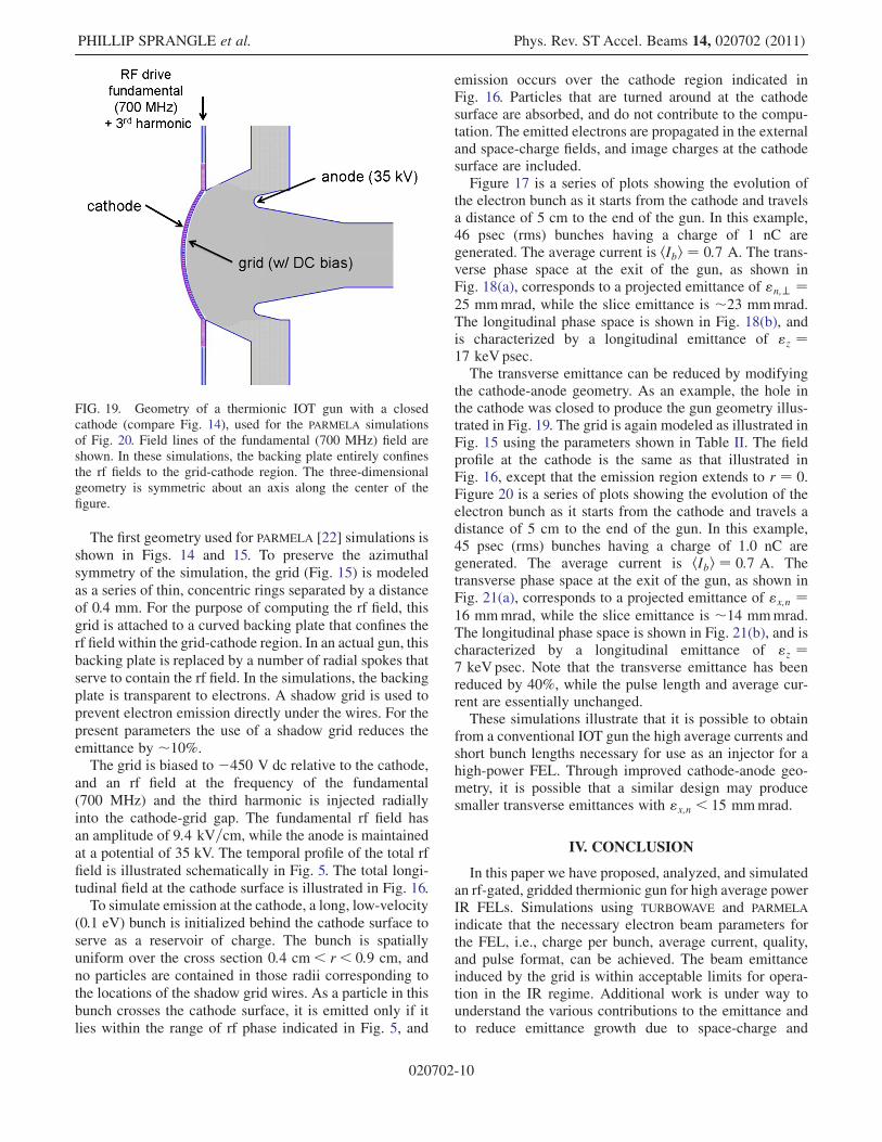
the cathode-anode geometry. As an example, the hole inthe cathode was closed to produce the gun geometry illus-trated in Fig. 19. The grid is again modeled as illustrated inFig. 15 using the parameters shown in Table II. The fieldprofile at the cathode is the same as that illustrated inFig. 16, except that the emission region extends to r ¼ 0.Figure 20 is a series of plots showing the evolution of theelectron bunch as it starts from the cathode and travels adistance of 5 cm to the end of the gun. In this example,45 psec (rms) bunches having a charge of 1.0 nC aregenerated. The average current is hIbi ¼ 0:7 A. Thetransverse phase space at the exit of the gun, as shown inFig. 21(a), corresponds to a projected emittance of "x;n ¼16 mmmrad, while the slice emittance is �14 mmmrad.The longitudinal phase space is shown in Fig. 21(b), and ischaracterized by a longitudinal emittance of "z ¼7 keV psec. Note that the transverse emittance has beenreduced by 40%, while the pulse length and average cur-rent are essentially unchanged.These simulations illustrate that it is possible to obtain
from a conventional IOT gun the high average currents andshort bunch lengths necessary for use as an injector for ahigh-power FEL. Through improved cathode-anode geo-metry, it is possible that a similar design may producesmaller transverse emittances with "x;n < 15 mmmrad.
IV. CONCLUSION
In this paper we have proposed, analyzed, and simulatedan rf-gated, gridded thermionic gun for high average powerIR FELs. Simulations using TURBOWAVE and PARMELA
indicate that the necessary electron beam parameters forthe FEL, i.e., charge per bunch, average current, quality,and pulse format, can be achieved. The beam emittanceinduced by the grid is within acceptable limits for opera-tion in the IR regime. Additional work is under way tounderstand the various contributions to the emittance andto reduce emittance growth due to space-charge and
FIG. 19. Geometry of a thermionic IOT gun with a closedcathode (compare Fig. 14), used for the PARMELA simulationsof Fig. 20. Field lines of the fundamental (700 MHz) field areshown. In these simulations, the backing plate entirely confinesthe rf fields to the grid-cathode region. The three-dimensionalgeometry is symmetric about an axis along the center of thefigure.
PHILLIP SPRANGLE et al. Phys. Rev. ST Accel. Beams 14, 020702 (2011)
020702-10
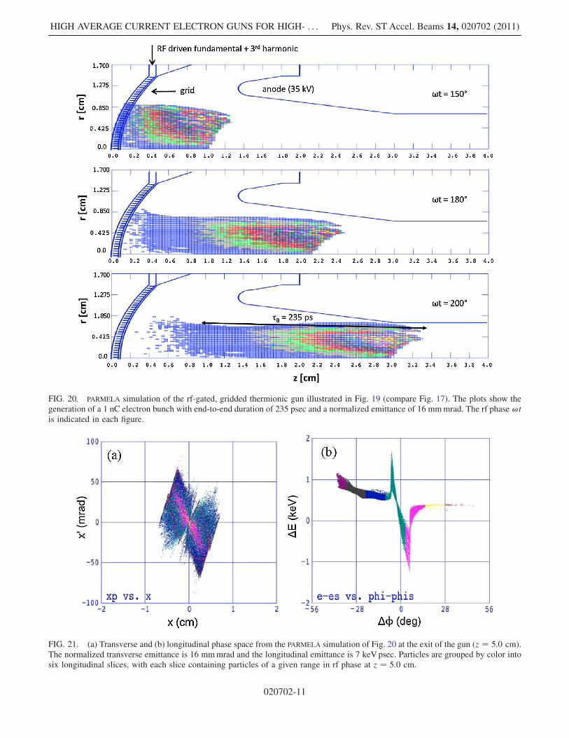
FIG. 20. PARMELA simulation of the rf-gated, gridded thermionic gun illustrated in Fig. 19 (compare Fig. 17). The plots show thegeneration of a 1 nC electron bunch with end-to-end duration of 235 psec and a normalized emittance of 16 mmmrad. The rf phase !tis indicated in each figure.
FIG. 21. (a) Transverse and (b) longitudinal phase space from the PARMELA simulation of Fig. 20 at the exit of the gun (z ¼ 5:0 cm).The normalized transverse emittance is 16 mmmrad and the longitudinal emittance is 7 keVpsec. Particles are grouped by color intosix longitudinal slices, with each slice containing particles of a given range in rf phase at z ¼ 5:0 cm.
HIGH AVERAGE CURRENT ELECTRON GUNS FOR HIGH- . . . Phys. Rev. ST Accel. Beams 14, 020702 (2011)
020702-11
macroscopic nonlinear effects by changing the gun geome-try and the use of emittance compensation coils [34].
The required high average current can be obtained withdispenser or single-crystal thermionic cathodes, which arerobust and have long lifetimes. Thermionic cathodes canprovide the necessary high average current, charge perbunch, and pulse format for high average power FELs.They operate at moderate vacuums (10�8–10�7 Torr),have long lifetimes (> 10 000 hours) delivering over 108
coulombs and can provide cathode current densities>10 A=cm2. The pulse duration requirements can be metby modulating the grid with a combination of the funda-mental and 3rd harmonic of the linac frequency, fillingevery rf bucket in the linac. The heat radiated by thethermionic gun in the proposed designed is relatively smalland, hence, it can be configured with either normal-conducting or superconducting prebooster cavities. Anexperimental program is under way at the NavalResearch Laboratory to demonstrate this high averagecurrent electron gun configuration.
ACKNOWLEDGMENTS
The authors are grateful to Professor P. Serafim foruseful discussions. This work was supported by theOffice of Naval Research. C. Mitchell is supported by aNational Research Council postdoctoral fellowship.
APPENDIX A: ELECTRON BEAMQUALITY REQUIREMENTS FOR FELS
The approximate beam quality requirements at the en-trance to the wiggler for high-power IR FEL operation arediscussed in this Appendix. In the FEL, the gain, growthrate, and efficiency are sensitively dependent on the axialvelocity spread ��z of the electrons. The electron beamquality is measured in terms of emittance and energyspread, the origins of which include (i) temperature ofthe cathode, (ii) roughness of the emitting surface,(iii) nonuniformity of the emission from the cathode sur-face, (iv) nonlinearity of electric and magnetic fields, and(v) self-fields. The electron bunch quality requirement forthe FEL, i.e.,��z < �=2Leff , at the entrance to the wigglercan be expressed by the following inequality [36]:
�Etotal=E < �wð1þ a2w=2Þ=ð4LeffÞ; (A1)
where the total longitudinal energy spread is
�Etotal=E ¼ "z=ð�bEÞ þ "2n;?=ð2R2bÞ þ �2a2wR
2b=ð2�2
wÞ:(A2)
In Eq. (A2), the first term represents the fractionalenergy spread due to longitudinal emittance "z, the sec-ond term arises from transverse rms emittance "n;?, andthe third term is due to transverse wiggler gradients. Theright-hand side of Eq. (A1) is the approximate FELconversion efficiency, where the effective interaction
length, Leff , is the gain length in the case of the amplifieror the wiggler length in the case of the oscillator, aw is thewiggler parameter, and �w is the wiggler period. If theinequality in Eq. (A1) is well satisfied, the spread inthe axial velocity of the electrons plays little role in theFEL interaction. As an example, for a MW-class FELoperating in the IR regime, the typical parameters are"n;? � 15 mmmrad, "z � 100 keV psec, Rb � 0:3 mm,
�b � 1 psec (rms), E ¼ 80 MeV, a2w ¼ 2, and �w ¼3 cm. For these parameters "z=ð�bEÞ 0:13%, "2n;?=ð2R2
bÞ � 0:13%, �2a2wR2b=ð2�2
wÞ � 0:1%, and �Etotal=E � 0:36%. For an amplifier having a gain length of30 cm the right-hand side of Eq. (A1) is � 5% and theinequality is satisfied. For an oscillator the right-hand sideof Eq. (A1) is �1=2Nw, where Nw is the number ofwiggler periods. For Nw ¼ 100 the inequality is alsosatisfied.
APPENDIX B: THERMIONIC INJECTORS
The gridded electron guns used as injectors for rf linacsin several notable FEL experiments, including theStanford, Boeing, and Novosibirsk FEL injectors, haveoperated at subharmonics of the main linac frequency,and have used short high voltage pulses synchronized tothe phase of the rf to gate the emission and generateelectron bunches suitable for injection into the subhar-monic cavities. The original Stanford FEL gun [16] wasthe first to use this approach, producing �200 pC,�1:3 nsec electron bunches at 11.8 MHz at the entranceof the normally conducting injector section of a 1.3 GHzsuperconducting linac.The Boeing FEL gun [14] produced 5.5 nC electron
bunches at �108 MHz, the 12th subharmonic of their1300 MHz linac, using a �1 kV, 2 nsec drive pulse tothe grid of an Eimac electron gun. Operating at the 12thsubharmonic accomplished two critical goals. First, it per-mitted the use of a relatively long high voltage pulse todrive the grid of the electron gun; operating the first rfcavity at 1.3 GHz while filling the same fraction of an rfperiod would have required the generation of a 170 psecdrive pulse as well as an rf gun capable of modulating thecurrent on that time scale. Second, it allowed the use ofsubharmonic bunching to increase the peak current to thelevel required for the FEL.However, the problem with subharmonic bunching is
that, while increasing peak current, it ultimately limitsthe average current, since it limits the fraction of rf bucketsthat are filled with electrons, while the charge in eachbucket is limited by space-charge effects. Using a similarapproach, the nonsuperconducting Energy Recovery LinacFEL in Novosibirsk [17] used a 300 keVelectron gun with�1 A of peak current in a 0.5 nsec rms pulse at a maximumrepetition rate of 22.5 MHz (eighth subharmonic of the�180 MHz linac). In this case, the maximum averagecurrent was �20 mA.
PHILLIP SPRANGLE et al. Phys. Rev. ST Accel. Beams 14, 020702 (2011)
020702-12
The SPring-8 FEL adopted an innovative approach toproducing a high brightness, bunched beam from a therm-ionic cathode without using a control grid [18,19]. Theexperiment employs a single-crystal CeB6 cathode to pro-duce a high current density 500 keV beam from an electrongun driven by a high-voltage modulator. At the exit to thegun, a beam with a 1 A peak current and 3 � sec pulsewidth at a maximum repetition rate of 60 Hz was gener-ated. A single nanosecond bunch is then generated fromeach pulse by means of a beam chopper. Thus, more than99.9% of the beam is deposited in a beam dump. Thisgridless approach thus solves the problem of producing aclean, low-emittance electron bunch, but at the cost ofdepositing most of the beam current in a beam dump, anapproach that is inconsistent with high average currentapplications.
A high average current injector should aim to fill every rfbucket. For a 700 MHz linac with no subharmonic section,a thermionic injector must generate electron bunches oforder 100 psec in pulse length at a 700 MHz pulse repeti-tion rate. Moreover, in order to produce an average currentof �1 A, the instantaneous current should be about anorder of magnitude higher. For such short bunches andhigh repetition rate, it is not practical to generate shorthigh-voltage pulses to apply to the grid of an electron gun,and direct rf modulation of the grid is required.
Gridded electron guns are used in inductive output tube(IOT) amplifiers [37–39] and can generate average currentsof �1 A, peak currents of �5–10 A, cathode-anode volt-ages of �35 kV, and modulation frequencies >1 GHz.These guns use low-temperature dispenser cathodes com-bined with grids fabricated from pyrolytic graphite, apolycrystalline form of carbon that will operate at hightemperatures and has improved strength and uniformitycompared to grids made of tungsten or molybdenum[37]. The grid is typically placed within �100–300 �mof the cathode to permit high-frequency current modula-tion. In typical operation, these guns are employed toproduce electron bunches filling 180 of rf phase in orderto generate the maximum rf power at the drive frequency.However, the degree of beammodulation is not constrainedto be 180 of the rf phase; it depends on the negative biasvoltage between the grid and the cathode (typically oforder 100–200 V) as well as the rf voltage induced in thecathode-grid gap. Shorter bunches can in principle beobtained by driving the grid circuit simultaneously at thefundamental rf frequency and a higher harmonic.
APPENDIX C: GRID FIELDSAND BEAM EMITTANCE
For the purpose of estimating the electron beam emit-tance due to a grid, we consider the 2D cathode, grid,anode configuration shown in Fig. 4. The grid wires forman infinite array located at z ¼ zG, are parallel to the y axisand are separated by a distance 2a. The radius of the gridwires is small, ro � a; zG. The grounded cathode is lo-cated at z ¼ 0 and the anode at z ¼ zA. The potential on thegrid relative to the cathode is denoted by �GðtÞ and con-sists of a dc bias and rf component while the anodepotential is �AðtÞ. In addition, the field in the anode-cathode gap induces a dipole field around each grid wire.The dipole field is localized around the grid wire and haslittle effect on the electron motion. Although the gridvoltage varies at the rf frequency, it can be considered tobe constant for the purpose of this calculation since theelectron transit time from the cathode to the grid, �G ¼zG=vz � 0:1 nsec, is small compared to the rf period,�rf � 1:4 nsec.
1. Potential for an array of grid wires
The potential associated with a single grid wire locatedat x ¼ 0 and z ¼ zG is
�ðx; zÞ ¼ ��O ln
�x2 þ ðz� zGÞ2x2 þ ðzþ zGÞ2
�þ�A
z
zA
��A
ðz� zGÞzA
�r2o
x2 þ ðz� zGÞ2�; (C1)
where �O ¼ ð1=2Þ½�GðtÞ ��AðtÞðzG=zAÞ�= lnð2zG=roÞ.In Eq. (C1) the first term is the potential of a line chargetogether with its image due to the cathode, the second termis due to the anode potential and the third term is due to theinduced dipole charges on the wire. For ro � a; zG thepotential on the cathode is zero, on the surface of the gridwire it is�GðtÞ and on the anode it is�AðtÞ. For the typicalparameters considered here j�Gj � 100 V, �A � 40 kV,zG � 250 �m, zA � 1 cm, a � 200 �m, ro � 30 �m,and lnð2zG=roÞ � 3.The fields associated with the single grid wire potential,
E ¼ �r�, are
Ex ¼ �2�O
�x
x2 þ ðzþ zGÞ2� x
x2 þ ðz� zGÞ2�� 2
�Ar2o
zA
� ðz� zGÞx½x2 þ ðz� zGÞ2�2
�; (C2a)
Ez ¼ �2�O
� ðzþ zGÞx2 þ ðzþ zGÞ2
� ðz� zGÞx2 þ ðz� zGÞ2
���A
zAþ�Ar
2o
zA
�x2 � ðz� zGÞ2
½x2 þ ðz� zGÞ2�2�: (C2b)
HIGH AVERAGE CURRENT ELECTRON GUNS FOR HIGH- . . . Phys. Rev. ST Accel. Beams 14, 020702 (2011)
020702-13

The dipole contribution, last term in Eqs. (C2), is smalland can be neglected near the cathode for zG � ro.
The potential due to an infinite array of grid wires,centered at z ¼ zG and x ¼ �a;�3a;�5a; . . . (seeFig. 7), is given by
�ðx; zÞ ¼ � Xn¼�1;�3;
��O ln
Gnðx; zÞFnðx; zÞ þ�A
r2oðz� zGÞ=zAGnðx; zÞ
�
þ�A
z
zA; (C3)
where �O¼ð1=2Þð�G��AzG=zAÞ½lnð2zG=roÞþMo��1,Fnðx; zÞ ¼ ðx� naÞ2 þ ðzþ zGÞ2, Gnðx; zÞ ¼ ðx�naÞ2 þ ðz� zGÞ2, and Mo ¼ P1
l¼1;2;3; ln½1þ z2G=ð‘2a2Þ�.The corresponding electric field in the cathode-anoderegion is
Ex ¼ �2X
n¼�1;�3;
��O
�x� na
Fnðx; zÞ �x� na
Gnðx; zÞ�þ�Ar
2o
zA
�ðz� zGÞðx� naÞG2
nðx; zÞ��
; (C4a)
Ez ¼ � Xn¼�1;�3;
�2�O
�zþ zGFnðx; zÞ �
z� zGGnðx; zÞ
���Ar
2o
zA
�ðx� naÞ2 � ðz� zGÞ2G2
nðx; zÞ��
��A
zA: (C4b)
The axial electric field at the surface of the cathode inthe absence of space-charge is
Ezðx;z¼0Þ¼��A=zA��ðxÞð�G=zG��A=zAÞ; (C5)
where the dipole term has been neglected and
�ðxÞ ¼�
2
lnð2zG=roÞ þMo
� Xn¼�1;�3;
z2Gðx� naÞ2 þ z2G
< 1
(C6)
is a shielding parameter. The grid wires partially shield theelectric fields associated with the anode potentials. Theelectron current is turned off when the grid potential issufficiently negative so that Ez > 0 on the cathode, that is,no current flows when
�G <��1��
�
�zGzA
�A: (C7)
2. Grid emittance estimate
The emittance growth due to the grid can be estimatedby calculating the rms angular deflection of the electrons asthey propagate from the cathode, through the grid region,to the anode (see Fig. 7). The rms normalized emittance (x
direction) is "n;x ¼ ��zðhx2ihðx0Þ2i � hxx0i2Þ1=2, where h idenotes an average over particles, � � 1 is the relativisticfactor, �z ¼ vz=c, vz is the axial beam velocity, and x0 ¼@x=@z. The normalized emittance is given by "n;x ���zRbh��i, where Rb is the rms beam radius and h��i ¼hvx=vzi is the rms deflection angle. The normalized gridemittance can therefore be written as "n;x � Rbhvx=ci. Inthe absence of self-fields the electron deflection velocity inthe x direction is given by @vx=@z ¼ ðq=mÞEx=vz, wherethe transverse electric field near the z axis, jxj< a, can beapproximated by Ex � �x@Ez=@z, where Ex and Ez arethe electric field components associated with the dc biasand rf fields.
The transverse deflection velocity at z ¼ 2zG is approxi-mately given by
vx � � q
m
Z 2zG
0
x
vz
@Ez
@zdz � � qx
mhvzi�Ez; (C8)
where �Ez ¼ Ezðx; 2zGÞ � Ezðx; 0Þ. It is assumed that thetransverse electron position changed little from its initialposition and hvzi is to be evaluated at z ¼ 2zG. Beyondz� 2zG the transverse velocity is approximately constant.For ro � a; zG, the effect of the dipole field part of thepotential on the average electron deflection can beneglected.To obtain an estimate for the emittance, we consider a
single wire centered at z ¼ zG and x ¼ 0, making use ofthe potential and fields given by Eqs. (C1) and (C2). Theaxial field difference, using Eq. (C2), is
�Ez � 4
3�1ðxÞ
��G
zG��A
zA
�; (C9)
where
�1ðxÞ ¼�
2
lnð2zG=roÞ�
z2Gðx2 þ z2GÞ
(C10)
is the shielding parameter associated with a single gridwire. The normalized transverse velocity at z ¼ 2zG is
�x � � 4
3
qx
mc2h�zi�1ðxÞ
��G
zG��A
zA
�: (C11)
To approximate the average deflection due to an arrayof grid wires we take x � �a. In this case the axial
velocity is h�zi � ½2q�ðx; zÞ=mc2�1=2 for h��i � 1,where �ðx; 2zGÞ � 2ðzG=zAÞ�A. The grid emittance istherefore given by
"n;grid�Rbh�xi�2�1ðaÞ3
�a
zG
�Rb
j ��G�ðzG=zAÞ ��AjðzG=zAÞ1=2 ��1=2
A
;
(C12)
PHILLIP SPRANGLE et al. Phys. Rev. ST Accel. Beams 14, 020702 (2011)
020702-14
where ��G ¼ jqj�G=ðmc2Þ and ��A ¼ jqj�A=ðmc2Þ. Theelectric field on the cathode for a single grid wire isEzðx; 0Þ ¼ ��A=zA ��1ðxÞð�G=zG ��A=zAÞ. Usingtypical values for the parameters, we find that h�zi � 2�10�2 and the normalized emittance due to the grid is"n;grid � 5–15 mmmrad.
A number of approximations were employed in obtain-ing the grid emittance. More accurate estimates for the gridemittance, which include self-field effects, are obtainedusing the PIC codes TURBOWAVE and PARMELA and arepresented in Sec. III.
[1] G. R. Neil, C. L. Bohn, S. V. Benson, G. Biallas, D.Douglas, H. F. Dylla, R. Evans, J. Fugitt, A. Grippo, J.Gubeli, R. Hill, K. Jordan, G. A. Krafft, R. Li, L.Merminga, P. Piot, J. Preble, M. Shinn, T. Siggins, R.Walker, and B. Yunn, Phys. Rev. Lett. 84, 662 (2000).
[2] ‘‘Free Electron Laser High Brightness, High AverageCurrent Injector’’ report to the NAVY HEL ProgramOffice (PMS-405) & Office of Naval Research,’’ P.O’Shea, Panel Chairman, 2002.
[3] A. Todd, Nucl. Instrum. Methods Phys. Res., Sect. A 557,36 (2006).
[4] I. Ben-Zvi and I. V. Bazarov, Nucl. Instrum. MethodsPhys. Res., Sect. A 557, 337 (2006).
[5] W. B. Colson, J. Blau, and R. L. Armstead, Nucl. Instrum.Methods Phys. Res., Sect. A 507, 48 (2003).
[6] D. C. Nguyen and H. P. Freund, Nucl. Instrum. MethodsPhys. Res., Sect. A 507, 120 (2003).
[7] P. Sprangle, B. Hafizi, and J. R. Penano, IEEE J. QuantumElectron. 40, 1739 (2004).
[8] I. Ben-Zvi, D. Kayran, and V. Litvinenko, in Proceedingsof the International FEL Conference, Stanford, CA, 2005,p. 232, http://www.jacow.org.
[9] P. Sprangle, J. Penano, B. Hafizi, and I. Ben-Zvi, IEEE J.Quantum Electron. 46, 1135 (2010).
[10] D. C. Nguyen et al., Nucl. Instrum. Methods Phys. Res.,Sect. A 528, 71 (2004).
[11] S. Benson et al., in Proceedings of the 2004 FELConference (Comitato Conferenze ELETTRA, Trieste,Italy, 2004), p. 229.
[12] K. L. Jensen et al., J. Appl. Phys. 102, 074902 (2007).[13] C. Hernandez-Garcia, T. Siggins, S. Benson, D. Bullard,
H. F. Dylla, K. Jordan, C. Murray, G. R. Neil, M. Shinn,and R. Walker, in Proceedings of the 21st ParticleAccelerator Conference, Knoxville, 2005 (IEEE,Piscataway, NJ, 2005), p. 3117; C. Hernandez-Garcia,P. G. O’Shea, and M. L. Stutzman, Phys. Today 61,No. 2, 44 (2008).
[14] A. Yeremian et al., in Proceedings of the ParticleAccelerator Conference, 1989. Accelerator Science andTechnology, Chicago, IL, USA (IEEE, Piscataway, NJ,1989), pp. 657–659.
[15] J.M. J. Madey, G. J. Ramian, and T. I. Smith, IEEE Trans.Nucl. Sci. 27, 999 (1980).
[16] T. I. Smith, Physics of Quantum Electronics, edited byS. F. Jacobs et al. (Addison-Wesley, Reading, MA, 1982),Vol. 8, pp. 77–87.
[17] V. P. Bolotin et al., in Proceedings of the 2004 FELConference (Comitato Conferenze ELETTRA, Trieste,Italy, 2004), pp. 226–228; S. V. Miginsky et al., inProceedings of the 2nd Annual Asian ParticleAccelerator Conference, Beijing, China, 2001,pp. 82–84, http://www.jacow.org.
[18] K. Togawa et al., Phys. Rev. STAccel. Beams 10, 020703(2007).
[19] T. Shintake et al., Phys. Rev. STAccel. Beams 12, 070701(2009).
[20] R. J. Bakker, C. A. J. van der Geer, A. F. G. vanderMeer,P.W. van Amersfoort, W.A. Gillespie, and G. Saxon,Nucl. Instrum. Methods Phys. Res., Sect. A 307, 543(1991).
[21] D. F. Gordon, W. B. Mori, and T.M. Antonsen, Jr., IEEETrans. Plasma Sci. 28, 1135 (2000); D. F. Gordon, IEEETrans. Plasma Sci. 35, 1486 (2007).
[22] J. H. Billen, PARMELA Documentation, Los Alamos ReportNo. LA-UR-96-1835, revised 2005.
[23] A. S. Gilmore, Principles of Travelling Wave Tubes(Artech House, Boston, MA, 1994).
[24] P. Frigola et al., in Proceedings of the 20th ParticleAccelerator Conference, Portland, OR, 2003 (IEEE,New York, 2003), http://www.jacow.org.
[25] R. Thomas, J. Gibson, G. Haas, and R.H. Abrams, Jr.,IEEE Trans. Electron Devices 37, 850 (1990).
[26] M. Reiser, Theory and Design of Charged Particle Beams(Wiley, New York, 1994).
[27] T. Wangler, RF Linear Accelerators (Wiley, New York,1998).
[28] R. C. Davidson, Physics of Nonneutral Plasmas (Addison-Wesley, Redwood, CA, 1990).
[29] R. Vaughan, IEEE Trans. Electron Devices 33, 1925(1986).
[30] S. H. Gold and G. S. Nusinovich, Rev. Sci. Instrum. 68,3945 (1997).
[31] Y. Y. Lau, Y. Liu, and R.K. Parker, Phys. Plasmas 1, 2082(1994).
[32] J. D. Jarvis et al., in Proceedings of the International FELConference, Gyeongju, Korea, 2008, p. 477, http://www.jacow.org.
[33] J. D. Lawson, The Physics of Charged-Particle Beams(Oxford University Press, Oxford, UK, 1988).
[34] L. Serafini and J. B. Rosenzweig, Phys. Rev. E 55, 7565(1997).
[35] Communications & Power Industries (CPI) (private com-munication).
[36] C.W. Roberson and P. Sprangle, Phys. Fluids B 1, 3(1989).
[37] E. G. Zaidman and M.A. Kodis, IEEE Trans. ElectronDevices 38, 2221 (1991).
[38] C. Beard, Nucl. Instrum. Methods Phys. Res., Sect. A 557,276 (2006).
[39] D. H. Priest and M. B. Shrader, Proc. IEEE 70, 1318(1982).
HIGH AVERAGE CURRENT ELECTRON GUNS FOR HIGH- . . . Phys. Rev. ST Accel. Beams 14, 020702 (2011)
020702-15
![[in2p3-00490983, v1] Present status and first results of ... fileFacility (ATF) at KEK [ 3] was built to create small emit- tance beams, and has succeeded in obtaining emittances *](https://img.pdfslide.net/doc/110x75/5d50cd2788c9936e548bd044/in2p3-00490983-v1-present-status-and-first-results-of-atf-at-kek-3-was.jpg)