Embed Size (px)
Citation preview
Application ReportSLVA474–July 2011
High-Efficiency AC-DC TV Power Solutions: Proposing anIntelligent LED Backlight Driving Scheme
Jimmy Liu, Pony Ma, Yoshio Katsura ........................................................... Power Management Products
ABSTRACT
LCD televisions designed with LED backlight are continuing to grow in popularity compared toconventional TV architectures that use cold cathode fluorescent lamp (CCFL) bulbs because of thesupreme feature set that these systems offer: greater brightness, higher contrast ratios, stylish thindesigns, and significantly lower power consumption. To derive the full potential of the LED-based LCDbacklight technology, however, it is important to achieve both good thermal design and precise backlightON-OFF control for good picture quality by using the greater color gamut and higher contrast ratio of theLED, and suppressing LCD TV motion blur.
This application note presents novel power architectures with regard to the ac-dc total power supply for anLCD TV design, achieving higher power efficiencies and lower cost. The revolutionary iHVM™ mechanismenables intelligent LED bias control to minimize power loss. On the other hand, the fast LED driversprovide precise LED ON-OFF control. In this report, two reference designs are discussed. The PMP4298is the basic topology reference design; this design consists of a primary ac-dc stage, a secondary boostdc-dc converter stage for the LED backlight, and a multi-channel LED driver. The PMP4298A is proposedas an advanced reference design that achieves a much higher efficiency and an overall lower cost byomitting the LED backlight dc-dc secondary stage. The LED driver is instead supplied directly from theac-dc primary power-based LED backlight solution. Performance results are also presented.
Contents1 Introduction .................................................................................................................. 22 Proposed LED Backlight TV Power Architectures ...................................................................... 33 iHVM Basics ................................................................................................................. 54 Advanced iHVM Feedback Design: Direct Feedback to Isolated AC-DC Power Stage ........................... 75 Protection Scheme ........................................................................................................ 116 Experimental Results ..................................................................................................... 137 Conclusion .................................................................................................................. 158 References ................................................................................................................. 16Appendix A Schematics ........................................................................................................ 16
List of Figures
1 Edge-Type LED Backlight LCD TV Power Conversion Scheme ..................................................... 3
2 PMP4298: Basic Architecture for LED Backlight LCD TV Power Supply............................................ 4
3 PMP4298A: Advanced Power Architecture for LED Backlight LCD TV ............................................. 5
4 PMP4298: iHVM Feedback Loop Integration into DC-DC Primary Feedback Loop ............................... 6
5 TLC5960 Application Circuit with LLC Resonant Converter........................................................... 8
6 AC-DC Power-Stage Direct Feedback Loop Integrated with iHVM Secondary Feedback ........................ 9
7 PMP4298A: AC-DC Power Stage Startup and iHVM Optimization Sequence .................................... 10
8 TLC5960 Total iHVM and Protection Scheme......................................................................... 11
9 LED Open Detection and VLED Optimization Through iHVM ......................................................... 12
10 LED Short Detection and VLED Optimization Through iHVM ......................................................... 12
11 PMP4298A Demonstration Fixture Test Setup ........................................................................ 14iHVM is a trademark of Texas Instruments.All other trademarks are the property of their respective owners.
1SLVA474–July 2011 High-Efficiency AC-DC TV Power Solutions: Proposing an Intelligent LEDBacklight Driving SchemeSubmit Documentation Feedback
Copyright © 2011, Texas Instruments Incorporated
Introduction www.ti.com
12 Total Efficiency Comparison at Full Load on VLED, 24 V and 5 V.................................................... 14
13 Power Factor at Full Load for PMP4298A ............................................................................. 14
14 Output Headroom Voltage Waveforms for PMP4298A: LED ON to OFF.......................................... 15
15 Output Headroom Voltage Waveforms for PMP4298A: LED OFF to ON.......................................... 15
16 PFC Stage Schematic for PMP4298 and PMP4298A ................................................................ 17
17 Auxiliary Flyback Converter Stage Schematic for PMP4298 and PMP4298A .................................... 18
18 LLC Converter Stage Schematic for PMP4298 ....................................................................... 19
19 LLC Converter Stage Schematic for PMP4298A...................................................................... 20
20 TLC5960 LED Driver Stage Schematic for PMP4298 ................................................................ 21
21 TLC5960 LED Driver Stage Schematic for PMP4298A .............................................................. 22
1 Introduction
Liquid crystal display (LCD) television has become a hot favorite for consumers worldwide, mostly as aresult of the superior technology adopted by the industry in the manufacturing processes for thesesystems. Since it was first introduced to the market, periodic improvements have been made in responseto user comments and complaints. Many new techniques continue to improve the performance of theseunits. Some of these techniques are unique to LCD television; light-emitting diode (or LED) backlighting isone of these improvements.
This new backlight design has been acknowledged as having enormous potential for television technologyand architecture. Some experts even theorize that LED backlight will eventually replace all other backlighttechniques in the near future. LEDs are now widely used in many LCD televisions regardless of size. LEDimplementation facilitates saturated colors and superior color reproduction. Compared to other methodsfor backlights, LEDs are the most popular system because of these advantages, among others:
1. Long lifetime: With a life span of 50,000 hours or more, LED technology is the most durable backlightsystem in the television industry.
2. Contrast ratio: The fast switching capability is one of the biggest advantages of solid-state backlightcompared to conventional backlight such as CCFL bulbs. In an LCD TV, this capability translates into adynamic contrast ratio, which is an important specification for an LCD TV set to achieve better picturequality.
3. Wide color gamut: LED backlight has the potential to provide a superior, wide range color gamut,especially with RGB LED backlight. Even with WLED backlight, color purity is much better than withCCFL backlighting; this benefit also increases the overall system picture quality.
4. Brightness: The light efficacy of LED technology is continuously improving, almost at the rate of twiceper decade. LCD TV makes full use of this benefit, not only for picture quality improvement or lowerpower consumption, but also in areas such as 3D-TV (theoretically, the brightness is halved to 2D-TV)and using LCD TVs out-of-doors.
5. TV design flexibility: Because the LED itself has a smaller dimension compared to traditional CCFLbacklighting, stylish new TV designs are achievable; for example, an edge-lit, wall-mounted TV set hasa thickness of less than 10 mm. These types of innovations are promoting new styles in many homes.
6. Low power consumption: As noted earlier, the LED has much higher light efficacy compared toconventional technologies. Therefore, an LED backlight TV set has lower power consumption.EnergyStar v4.0/v5.0 and California Energy Commission (CEC) standards control power consumptionperformance for LCD TVs with different size panels. For example, for a 42-inch panel, the EnergyStarv4.0 (May 2010) regulation required that the maximum input power should be less than 115 W; theCEC Tier1 (January 2011) standard requires a maximum input power of less than 183 W.Conventional CCFL backlight technology is unable to meet these regulations; as a result, LEDbacklight technology is the first choice for system designers.
7. Environmentally friendly TV: An LED backlight LCD TV set contains no mercury, so it is easier todispose of and more easily recycled than other types of LCD TVs. This is the primary reason thatmany environmentalists also support LED TVs over other TV technologies.
2 High-Efficiency AC-DC TV Power Solutions: Proposing an Intelligent LED SLVA474–July 2011Backlight Driving Scheme Submit Documentation Feedback
Copyright © 2011, Texas Instruments Incorporated
Isolated AC/DC
Power Board
DC/DC
LED Driver
24 VDC
LCD Panel
AC
www.ti.com Proposed LED Backlight TV Power Architectures
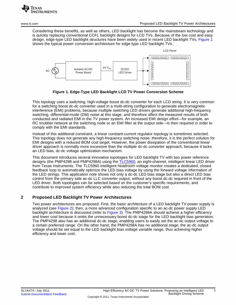
Considering these benefits, as well as others, LED backlight has become the mainstream technology andis quickly replacing conventional CCFL backlight designs for LCD TVs. Because of the low cost and easydesign, edge-type LED backlight structures have been widely used in recent LED backlight TVs. Figure 1shows the typical power conversion architecture for edge-type LED backlight TVs.
Figure 1. Edge-Type LED Backlight LCD TV Power Conversion Scheme
This topology uses a switching, high-voltage boost dc-dc converter for each LCD string. It is very commonfor a switching boost dc-dc converter used in a multi-string configuration to generate electromagneticinterference (EMI) problems, because multiple switching LED drivers generate additional high-frequencyswitching, differential-mode (DM) noise at this stage, and therefore affect the measured results of bothconducted and radiated EMI in the TV power system. An increased EMI design effort—for example, anRC snubber network at the switching node or an EMI filter at the output side—is then required in order tocomply with the EMI standards.
Instead of this additional constraint, a linear constant-current regulator topology is sometimes selected.This topology does not generate any high-frequency switching noise; therefore, it is the perfect solution forEMI designs with a reduced BOM cost target. However, the power dissipation of the conventional lineardriver approach is normally more excessive than the multiple dc-dc converter approach, because it lacksan LED bias, dc-dc voltage optimization mechanism.
This document introduces several innovative topologies for LED backlight TV with two power referencedesigns (the PMP4298 and PMP4298A) using the TLC5960, an eight-channel, intelligent linear LED driverfrom Texas Instruments. The TLC5960 intelligent headroom voltage monitor creates a dedicated, closedfeedback loop to automatically optimize the LED bias voltage by using the forward voltage information ofthe LED strings. This application note shows not only a dc-dc LED bias stage but also a direct LED biascontrol from the primary side ac-dc LLC converter output, without any boost dc-dc required in front of theLED driver. Both topologies can be selected based on the customer’s specific requirements, andcontribute to improved system efficiency while also reducing the total BOM cost.
2 Proposed LED Backlight TV Power Architectures
Two power architectures are proposed. First, the basic architecture of a LED backlight TV power supply isanalyzed (see Figure 2); then, a more advanced configuration specific to an ac-dc power supply LEDbacklight architecture is discussed (refer to Figure 3). The PMP4298A should achieve a higher efficiencyand lower cost because it omits the unnecessary boost dc-dc stage for the LED backlight bias generation.The PMP4298 also has an additional dc-dc stage, enabling users to easily set the ac-dc output voltage toa certain preferred range. On the other hand, the PMP4298A has no additional stage; the ac-dc outputvoltage should be set equal to the LED backlight bias voltage variable range, thus achieving higherefficiency and lower cost.
3SLVA474–July 2011 High-Efficiency AC-DC TV Power Solutions: Proposing an Intelligent LEDBacklight Driving SchemeSubmit Documentation Feedback
Copyright © 2011, Texas Instruments Incorporated
TM PFC
UCC28501
LLC Control
UCC25600
System
Flyback
UCC28610
Boost DC/DC
TPS40210
VREF
TLC5960 Constant Current LED Driver
Eight-Channel
Light Bar
20 LEDs
in series
R2
R1
80 VDC48 VDC
24 V at
2 A for
audio and
system
FB
iHVM
5 V at 3 A
for system
5 V at 1 A
for standby
Proposed LED Backlight TV Power Architectures www.ti.com
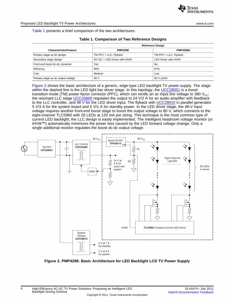
Table 1 presents a brief comparison of the two architectures.
Table 1. Comparison of Two Reference Designs
Reference Design
Characteristic/Feature PMP4298 PMP4298A
Primary stage ac-dc design TM PFC + LLC, Flyback TM PFC + LLC, Flyback
Secondary stage design DC-DC + LED Driver with iHVM LED Driver with iHVM
Front-end boost dc-dc converter Yes No
Efficiency 85% 87%
Cost Medium Low
Primary stage ac-dc output voltage 48 V 80 V ±10%
Figure 2 shows the basic architecture of a generic, edge-type LED backlight TV power supply. The stagewithin the dashed line is the LED light bar driver stage. In this topology, the UCC28051 is a boosttransition mode (TM) power factor corrector (PFC), which can rectify an ac input line voltage to 380 VDC;the resonant LLC stage UCC25600 regulates the output to 24 V/2 A for an audio amplifier with feedbackto the LLC controller, and 48 V for the LED driver input. The flyback with UCC28610 in parallel generates5 V/3 A for the system board and 5 V/1 A for standby power. In the LED driver stage, the 48-V inputvoltage requires another front-end boost stage to boost the output voltage to 80 V, which connects to theeight-channel TLC5960 with 20 LEDs at 120 mA per string. This technique is the most common type ofcurrent LED backlight; the LLC design is easily implemented. The intelligent headroom voltage monitor (oriHVM™) automatically minimizes the power loss caused by the LED forward voltage change. Only asingle additional resistor regulates the boost dc-dc output voltage.
Figure 2. PMP4298: Basic Architecture for LED Backlight LCD TV Power Supply
4 High-Efficiency AC-DC TV Power Solutions: Proposing an Intelligent LED SLVA474–July 2011Backlight Driving Scheme Submit Documentation Feedback
Copyright © 2011, Texas Instruments Incorporated
TM PFC
UCC28501
LLC Control
UCC25600
System
Flyback
UCC28610
VREF
TLC5960 Constant Current LED Driver
Eight-Channel
Light Bar
20 LEDs
in series
R2
R1
~80 VDC
24 V at 2 A for
audio and
system
5 V at 3 A
for system
5 V at 1 A
for standby
iHVM
www.ti.com iHVM Basics
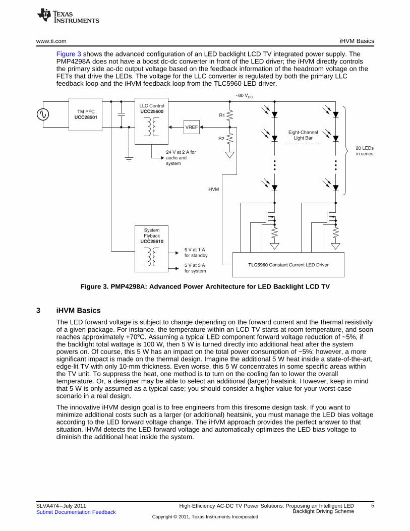
Figure 3 shows the advanced configuration of an LED backlight LCD TV integrated power supply. ThePMP4298A does not have a boost dc-dc converter in front of the LED driver; the iHVM directly controlsthe primary side ac-dc output voltage based on the feedback information of the headroom voltage on theFETs that drive the LEDs. The voltage for the LLC converter is regulated by both the primary LLCfeedback loop and the iHVM feedback loop from the TLC5960 LED driver.
Figure 3. PMP4298A: Advanced Power Architecture for LED Backlight LCD TV
3 iHVM Basics
The LED forward voltage is subject to change depending on the forward current and the thermal resistivityof a given package. For instance, the temperature within an LCD TV starts at room temperature, and soonreaches approximately +70ºC. Assuming a typical LED component forward voltage reduction of ~5%, ifthe backlight total wattage is 100 W, then 5 W is turned directly into additional heat after the systempowers on. Of course, this 5 W has an impact on the total power consumption of ~5%; however, a moresignificant impact is made on the thermal design. Imagine the additional 5 W heat inside a state-of-the-art,edge-lit TV with only 10-mm thickness. Even worse, this 5 W concentrates in some specific areas withinthe TV unit. To suppress the heat, one method is to turn on the cooling fan to lower the overalltemperature. Or, a designer may be able to select an additional (larger) heatsink. However, keep in mindthat 5 W is only assumed as a typical case; you should consider a higher value for your worst-casescenario in a real design.
The innovative iHVM design goal is to free engineers from this tiresome design task. If you want tominimize additional costs such as a larger (or additional) heatsink, you must manage the LED bias voltageaccording to the LED forward voltage change. The iHVM approach provides the perfect answer to thatsituation. iHVM detects the LED forward voltage and automatically optimizes the LED bias voltage todiminish the additional heat inside the system.
5SLVA474–July 2011 High-Efficiency AC-DC TV Power Solutions: Proposing an Intelligent LEDBacklight Driving SchemeSubmit Documentation Feedback
Copyright © 2011, Texas Instruments Incorporated
V =LED V +REF (V V )REF - HVM
R1 + R2
R2
R1
R3
RS RS
D1
G1
S1
iHVM
iHVM
Process
Core
TLC5960
LED Driver
COUT
R1
R2
R3
VLED
VFB
VREF
TPS40210
Primary Loop Secondary Loop
Sinking
Sourcing
DC/DC
iHVM Basics www.ti.com
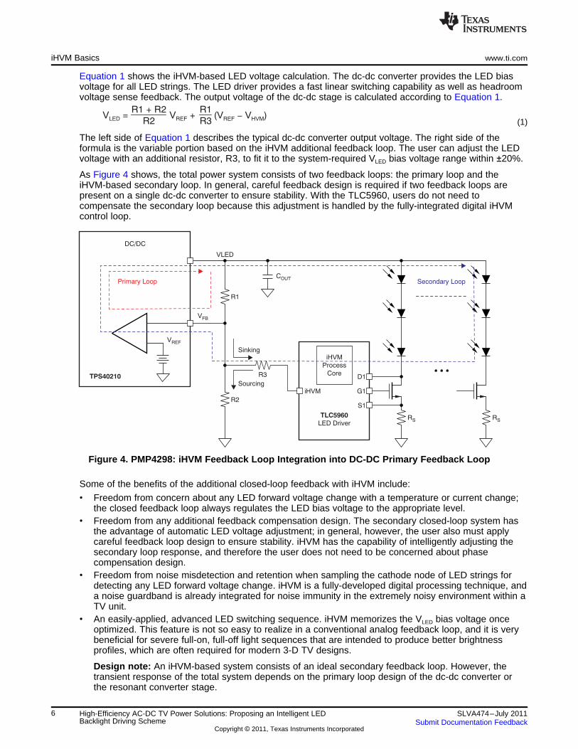
Equation 1 shows the iHVM-based LED voltage calculation. The dc-dc converter provides the LED biasvoltage for all LED strings. The LED driver provides a fast linear switching capability as well as headroomvoltage sense feedback. The output voltage of the dc-dc stage is calculated according to Equation 1.
(1)
The left side of Equation 1 describes the typical dc-dc converter output voltage. The right side of theformula is the variable portion based on the iHVM additional feedback loop. The user can adjust the LEDvoltage with an additional resistor, R3, to fit it to the system-required VLED bias voltage range within ±20%.
As Figure 4 shows, the total power system consists of two feedback loops: the primary loop and theiHVM-based secondary loop. In general, careful feedback design is required if two feedback loops arepresent on a single dc-dc converter to ensure stability. With the TLC5960, users do not need tocompensate the secondary loop because this adjustment is handled by the fully-integrated digital iHVMcontrol loop.
Figure 4. PMP4298: iHVM Feedback Loop Integration into DC-DC Primary Feedback Loop
Some of the benefits of the additional closed-loop feedback with iHVM include:
• Freedom from concern about any LED forward voltage change with a temperature or current change;the closed feedback loop always regulates the LED bias voltage to the appropriate level.
• Freedom from any additional feedback compensation design. The secondary closed-loop system hasthe advantage of automatic LED voltage adjustment; in general, however, the user also must applycareful feedback loop design to ensure stability. iHVM has the capability of intelligently adjusting thesecondary loop response, and therefore the user does not need to be concerned about phasecompensation design.
• Freedom from noise misdetection and retention when sampling the cathode node of LED strings fordetecting any LED forward voltage change. iHVM is a fully-developed digital processing technique, anda noise guardband is already integrated for noise immunity in the extremely noisy environment within aTV unit.
• An easily-applied, advanced LED switching sequence. iHVM memorizes the VLED bias voltage onceoptimized. This feature is not so easy to realize in a conventional analog feedback loop, and it is verybeneficial for severe full-on, full-off light sequences that are intended to produce better brightnessprofiles, which are often required for modern 3-D TV designs.
Design note: An iHVM-based system consists of an ideal secondary feedback loop. However, thetransient response of the total system depends on the primary loop design of the dc-dc converter orthe resonant converter stage.
6 High-Efficiency AC-DC TV Power Solutions: Proposing an Intelligent LED SLVA474–July 2011Backlight Driving Scheme Submit Documentation Feedback
Copyright © 2011, Texas Instruments Incorporated

www.ti.com Advanced iHVM Feedback Design: Direct Feedback to Isolated AC-DC Power Stage
4 Advanced iHVM Feedback Design: Direct Feedback to Isolated AC-DC Power Stage
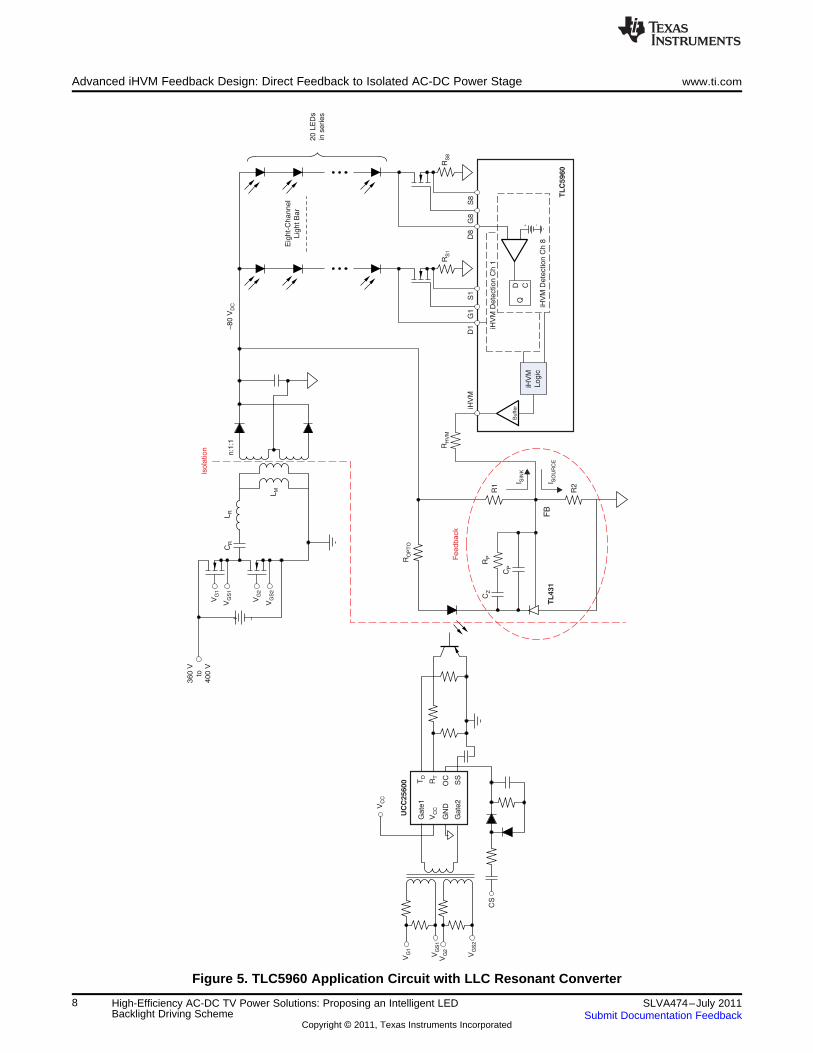
iHVM is designed to be flexible and to work well with various configurations of primary feedback loops.iHVM can work with a non-isolated dc-dc power stage design (based on the PMP4298 and theTPS40210), and is also easily configurable with an isolated ac-dc power stage (using the PMP4298A andthe UCC25600 directly). Figure 5 illustrates the PMP4298A application circuitry with an LLC resonantcontroller with feedback through isolation. Up to four feedback connections can be controlled fromTLC5960 iHVM buffers; output levels are automatically adjusted through an internal iHVM mechanism toimprove the linear LED driver efficiency.
Here, the LLC resonant converter output with variable frequency is regulated based on the shunt currentthrough the TL431 voltage reference device. At the reference node of the TL431 (designated as the FBnode), the voltage divider R1 and R2 is connected to define the primary feedback loop voltage. The iHVMmechanism feeds the LED forward voltage information back to the FB node through RHVM and adjusts theLLC resonant converter output voltage according to the required LED forward voltage.
To sense the LED forward voltage in strings, the TLC5960 monitors the FET drain node voltage of eachstring first. Next, the TLC5960 processes the obtained information in an intelligent digital power logicblock. Finally, the TLC5960 modulates the HVM pin output voltage, which adjusts the UCC25600operating frequency to achieve an optimized output voltage, VLED.
7SLVA474–July 2011 High-Efficiency AC-DC TV Power Solutions: Proposing an Intelligent LEDBacklight Driving SchemeSubmit Documentation Feedback
Copyright © 2011, Texas Instruments Incorporated
TL
C5
96
0
Eig
ht-
Ch
an
ne
l
Lig
ht
Ba
r
20
LE
Ds
in s
erie
s
~8
0 V
DC
RS
1R
S8
+ -
D1
D8
G1
G8
S1
S8
D CQ
iHV
M D
ete
ctio
n C
h 8
iHV
M D
ete
ctio
n C
h 1
iHV
M
Lo
gic
Buffer
R1
R2
RPRO
PT
O
I SIN
K
I SO
UR
CE
RH
VM
iHV
M
CZ
CP
CR
TL
43
1
n:1
:1
LM
LR
VG
1
VG
2
VG
S1
VG
S2
+ -
36
0 V
to
40
0 V
Fe
ed
ba
ck
Iso
latio
n
VG
1
VG
S2
CS
VG
2
VG
S1
TD
RT
OC
SS
Ga
te1
Ga
te2
VC
CVC
C
GN
D
UC
C2
56
00
FB
Advanced iHVM Feedback Design: Direct Feedback to Isolated AC-DC Power Stage www.ti.com
Figure 5. TLC5960 Application Circuit with LLC Resonant Converter
8 High-Efficiency AC-DC TV Power Solutions: Proposing an Intelligent LED SLVA474–July 2011Backlight Driving Scheme Submit Documentation Feedback
Copyright © 2011, Texas Instruments Incorporated
RS RS
D1
G1
S1
HVM1
iHVM
Process
Core
TLC5960
LED Driver
COUT
R1
R2
R3
VLED
VFB
VREF
Voltage
Feedback
Loop
iHVM
Feedback
Loop
ISINK
ISOURCE
400 V
LLC
Controller
13 V
www.ti.com Advanced iHVM Feedback Design: Direct Feedback to Isolated AC-DC Power Stage
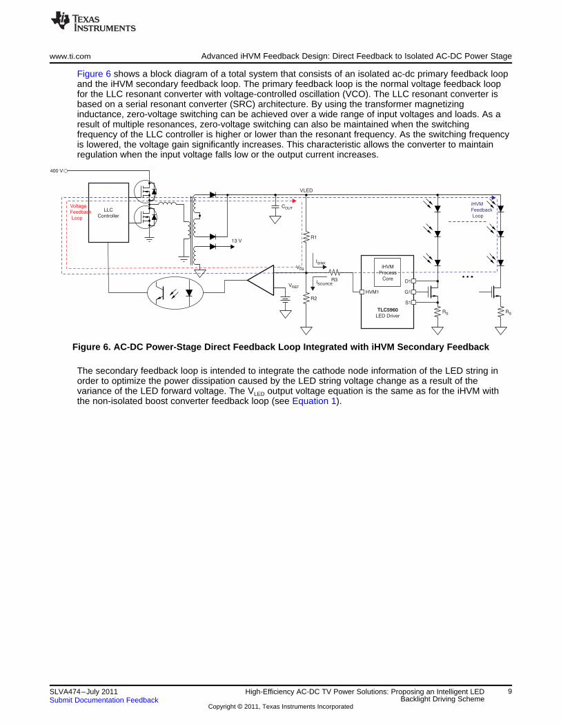
Figure 6 shows a block diagram of a total system that consists of an isolated ac-dc primary feedback loopand the iHVM secondary feedback loop. The primary feedback loop is the normal voltage feedback loopfor the LLC resonant converter with voltage-controlled oscillation (VCO). The LLC resonant converter isbased on a serial resonant converter (SRC) architecture. By using the transformer magnetizinginductance, zero-voltage switching can be achieved over a wide range of input voltages and loads. As aresult of multiple resonances, zero-voltage switching can also be maintained when the switchingfrequency of the LLC controller is higher or lower than the resonant frequency. As the switching frequencyis lowered, the voltage gain significantly increases. This characteristic allows the converter to maintainregulation when the input voltage falls low or the output current increases.
Figure 6. AC-DC Power-Stage Direct Feedback Loop Integrated with iHVM Secondary Feedback
The secondary feedback loop is intended to integrate the cathode node information of the LED string inorder to optimize the power dissipation caused by the LED string voltage change as a result of thevariance of the LED forward voltage. The VLED output voltage equation is the same as for the iHVM withthe non-isolated boost converter feedback loop (see Equation 1).
9SLVA474–July 2011 High-Efficiency AC-DC TV Power Solutions: Proposing an Intelligent LEDBacklight Driving SchemeSubmit Documentation Feedback
Copyright © 2011, Texas Instruments Incorporated
0
70
0
5
1.2
0.7
0
V (V)HVM
V (V)LED
EN (V)
TLC5960/iHVM(O)
TLC5960/EN(I)
iHVM
Optimization
start when
TLC5960 is
enabled
iHVM
Optimization
hold at
EN = L
iHVM Found
Settling Point
LED V Change
DetectedF
iHVM Found
Settling Point
Default 0.7-V Output
1.25 V
0.14 V
AC/DC Default
Output Level
R1 + R2
R2VREF
R1
R3(VREF HVMV )-
80 V
60 V iHVM Adjustable
Range
iHVM Output
Starts to Adjust
AC/DC Output
Initiated AC/DC
Power Supply
iHVM Optimization
(EN = H)
iHVM Hold
(EN = L)
iHVM Initialization
(EN = L)
Time (s)
iHVM Output
Range
Advanced iHVM Feedback Design: Direct Feedback to Isolated AC-DC Power Stage www.ti.com
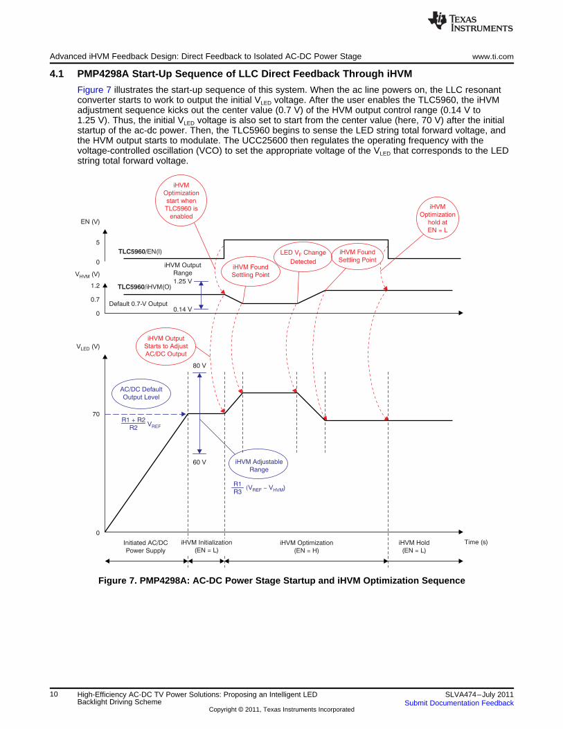
4.1 PMP4298A Start-Up Sequence of LLC Direct Feedback Through iHVM
Figure 7 illustrates the start-up sequence of this system. When the ac line powers on, the LLC resonantconverter starts to work to output the initial VLED voltage. After the user enables the TLC5960, the iHVMadjustment sequence kicks out the center value (0.7 V) of the HVM output control range (0.14 V to1.25 V). Thus, the initial VLED voltage is also set to start from the center value (here, 70 V) after the initialstartup of the ac-dc power. Then, the TLC5960 begins to sense the LED string total forward voltage, andthe HVM output starts to modulate. The UCC25600 then regulates the operating frequency with thevoltage-controlled oscillation (VCO) to set the appropriate voltage of the VLED that corresponds to the LEDstring total forward voltage.
Figure 7. PMP4298A: AC-DC Power Stage Startup and iHVM Optimization Sequence
10 High-Efficiency AC-DC TV Power Solutions: Proposing an Intelligent LED SLVA474–July 2011Backlight Driving Scheme Submit Documentation Feedback
Copyright © 2011, Texas Instruments Incorporated
TLC5960
LED
Short
LED
Short
LED
Open
LED
Open
On
On
On
LED Open (LOD)
LED Short (LSD)
HVM-
HVM+
iHVM Logic
Protection
Logic
Dn
iHVM
Feedback
XFLT
Error Out
iHVM
Status
Info
R1R3
R2
FB
TPS40210
UCC25600
(PMP4298)
or
(PMP4298A)
VLED
VIN
www.ti.com Protection Scheme
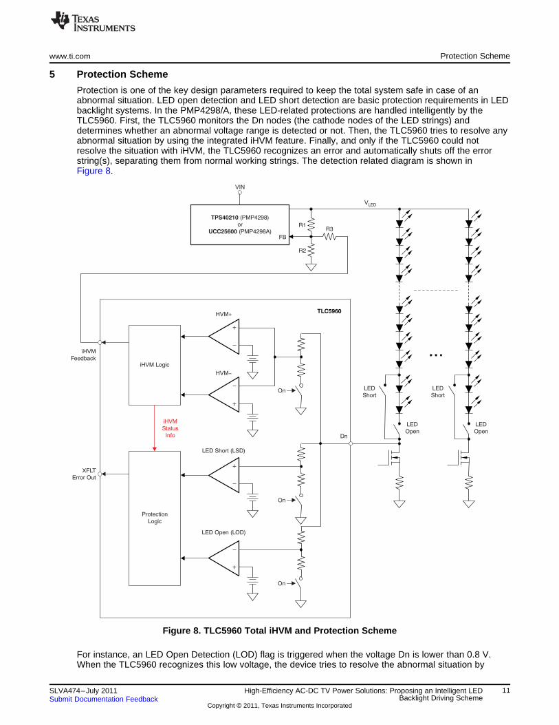
5 Protection Scheme
Protection is one of the key design parameters required to keep the total system safe in case of anabnormal situation. LED open detection and LED short detection are basic protection requirements in LEDbacklight systems. In the PMP4298/A, these LED-related protections are handled intelligently by theTLC5960. First, the TLC5960 monitors the Dn nodes (the cathode nodes of the LED strings) anddetermines whether an abnormal voltage range is detected or not. Then, the TLC5960 tries to resolve anyabnormal situation by using the integrated iHVM feature. Finally, and only if the TLC5960 could notresolve the situation with iHVM, the TLC5960 recognizes an error and automatically shuts off the errorstring(s), separating them from normal working strings. The detection related diagram is shown inFigure 8.
Figure 8. TLC5960 Total iHVM and Protection Scheme
For instance, an LED Open Detection (LOD) flag is triggered when the voltage Dn is lower than 0.8 V.When the TLC5960 recognizes this low voltage, the device tries to resolve the abnormal situation by
11SLVA474–July 2011 High-Efficiency AC-DC TV Power Solutions: Proposing an Intelligent LEDBacklight Driving SchemeSubmit Documentation Feedback
Copyright © 2011, Texas Instruments Incorporated
0.81.6
2.6
Dn (V)
0.14
0.7
1.25
V (V)HVM
5
0
XFLT (V)
80
70
60
V (V)LED
iHVM
Detection
Range
V Range
Corresponding to
iHVM Range
LED
V Reaches
Max ValueLED
Error Output
HVM Output
Reaches Min
Dn Unable to
Recover (Error Status)
Error String
Shut OffDn Voltage Recovers
(Normal Status)
LED V
Changes
Again
FLED V Change
Drives HVM LowerF
V Driven
HigherLED
V Settles
OnceLED
iHVM
Controls
VLED
Normal Status iHVM
Optimize
iHVM
Optimize
Normal Error
Status
HVM Output
Range
iHVM
Detection
Range
V Range
Corresponding to
iHVM Range
LED
V Reaches
Min ValueLED
Error Output
HVM Output
Reaches Max
Dn Unable to
Recover (Error Status)
Error String
Shut Off
Dn Voltage Recovers
(Normal Status)
LED V
Changes
Again
F
1.6
2.6
9.5
Dn (V)
1.25
0.7
0.14
XFLT (V)
5
0
V (V)LED
80
70
60
LED V Change
Drives HVM HigherF
V (V)HVM
V Driven
LowLED
V Settles
OnceLED
iHVM
Controls
VLED
Normal Status iHVM
Optimize
iHVM
Optimize
Normal Error
Status
Protection Scheme www.ti.com
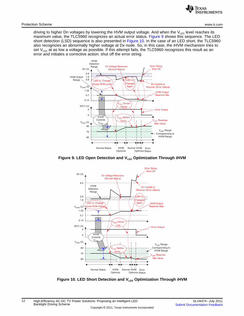
driving to higher Dn voltages by lowering the HVM output voltage. And when the VLED level reaches itsmaximum value, the TLC5960 recognizes an actual error status. Figure 9 shows this sequence. The LEDshort detection (LSD) sequence is also presented in Figure 10. In the case of an LED short, the TLC5960also recognizes an abnormally higher voltage at Dx node. So, in this case, the iHVM mechanism tries toset VLED at as low a voltage as possible. If this attempt fails, the TLC5960 recognizes this result as anerror and initiates a corrective action: shut off the error string.
Figure 9. LED Open Detection and VLED Optimization Through iHVM
Figure 10. LED Short Detection and VLED Optimization Through iHVM
12 High-Efficiency AC-DC TV Power Solutions: Proposing an Intelligent LED SLVA474–July 2011Backlight Driving Scheme Submit Documentation Feedback
Copyright © 2011, Texas Instruments Incorporated
www.ti.com Experimental Results
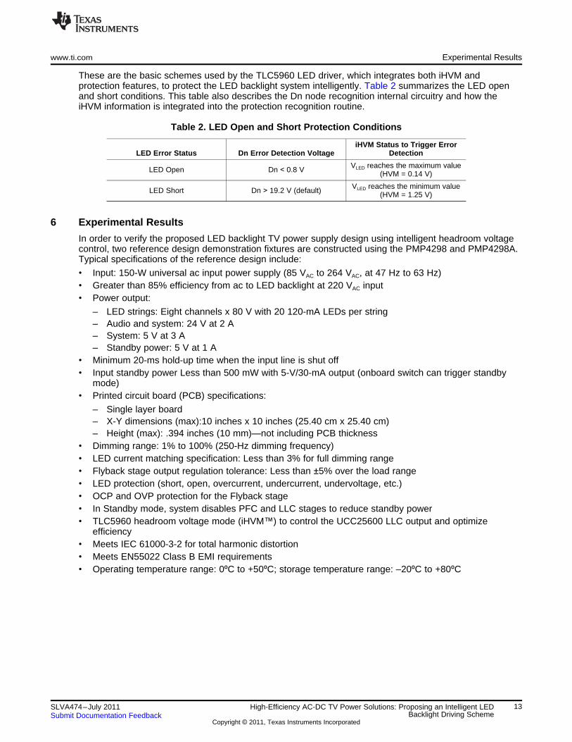
These are the basic schemes used by the TLC5960 LED driver, which integrates both iHVM andprotection features, to protect the LED backlight system intelligently. Table 2 summarizes the LED openand short conditions. This table also describes the Dn node recognition internal circuitry and how theiHVM information is integrated into the protection recognition routine.
Table 2. LED Open and Short Protection Conditions
iHVM Status to Trigger ErrorLED Error Status Dn Error Detection Voltage Detection
VLED reaches the maximum valueLED Open Dn < 0.8 V (HVM = 0.14 V)
VLED reaches the minimum valueLED Short Dn > 19.2 V (default) (HVM = 1.25 V)
6 Experimental Results
In order to verify the proposed LED backlight TV power supply design using intelligent headroom voltagecontrol, two reference design demonstration fixtures are constructed using the PMP4298 and PMP4298A.Typical specifications of the reference design include:
• Input: 150-W universal ac input power supply (85 VAC to 264 VAC, at 47 Hz to 63 Hz)• Greater than 85% efficiency from ac to LED backlight at 220 VAC input• Power output:
– LED strings: Eight channels x 80 V with 20 120-mA LEDs per string– Audio and system: 24 V at 2 A– System: 5 V at 3 A– Standby power: 5 V at 1 A
• Minimum 20-ms hold-up time when the input line is shut off• Input standby power Less than 500 mW with 5-V/30-mA output (onboard switch can trigger standby
mode)• Printed circuit board (PCB) specifications:
– Single layer board– X-Y dimensions (max):10 inches x 10 inches (25.40 cm x 25.40 cm)– Height (max): .394 inches (10 mm)—not including PCB thickness
• Dimming range: 1% to 100% (250-Hz dimming frequency)• LED current matching specification: Less than 3% for full dimming range• Flyback stage output regulation tolerance: Less than ±5% over the load range• LED protection (short, open, overcurrent, undercurrent, undervoltage, etc.)• OCP and OVP protection for the Flyback stage• In Standby mode, system disables PFC and LLC stages to reduce standby power• TLC5960 headroom voltage mode (iHVM™) to control the UCC25600 LLC output and optimize
efficiency• Meets IEC 61000-3-2 for total harmonic distortion• Meets EN55022 Class B EMI requirements• Operating temperature range: 0ºC to +50ºC; storage temperature range: –20ºC to +80ºC
13SLVA474–July 2011 High-Efficiency AC-DC TV Power Solutions: Proposing an Intelligent LEDBacklight Driving SchemeSubmit Documentation Feedback
Copyright © 2011, Texas Instruments Incorporated
5-V System Load
5-V Standby Load
Eight-String
LED Light Bar
PMP4298A Demo Board
24-V DC Load
90 110 130 150 170 190 210 230 250
Input Voltage (V)
0.9
0.89
0.88
0.87
0.86
0.85
0.84
0.83
0.82
Effic
iency (
%)
EFFICIENCY COMPARISON
PMP4298
PMP4298A
264
Input Voltage (V)
1
0.99
0.98
0.97
0.96
0.95
0.94
0.93
0.92
0.91
0.9
Pow
er
Facto
r
POWER FACTOR vs INPUT VOLTAGE
90 110 130 150 170 190 210 230 250 264
Experimental Results www.ti.com
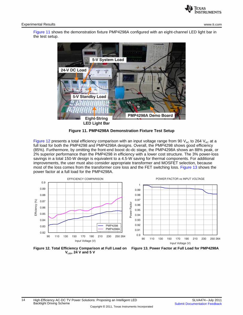
Figure 11 shows the demonstration fixture PMP4298A configured with an eight-channel LED light bar inthe test setup.
Figure 11. PMP4298A Demonstration Fixture Test Setup
Figure 12 presents a total efficiency comparison with an input voltage range from 90 VAC to 264 VAC at afull load for both the PMP4298 and PMP4298A designs. Overall, the PMP4298 shows good efficiency(85%). Furthermore, by omitting the front-end boost dc-dc stage, the PMP4298A shows an 88% peak, or2% superior performance than the PMP4298 in efficiency with a lower cost structure. The 3% power-losssavings in a total 150-W design is equivalent to a 4.5-W saving for thermal components. For additionalimprovements, the user must also consider appropriate transformer and MOSFET selection, becausemost of the loss comes from the transformer core loss and the FET switching loss. Figure 13 shows thepower factor at a full load for the PMP4298A.
Figure 12. Total Efficiency Comparison at Full Load on Figure 13. Power Factor at Full Load for PMP4298AVLED, 24 V and 5 V
14 High-Efficiency AC-DC TV Power Solutions: Proposing an Intelligent LED SLVA474–July 2011Backlight Driving Scheme Submit Documentation Feedback
Copyright © 2011, Texas Instruments Incorporated
(a) 50% PWM Dimming (b) 90% PWM Dimming
(a) 50% PWM Dimming (b) 90% PWM Dimming
www.ti.com Conclusion
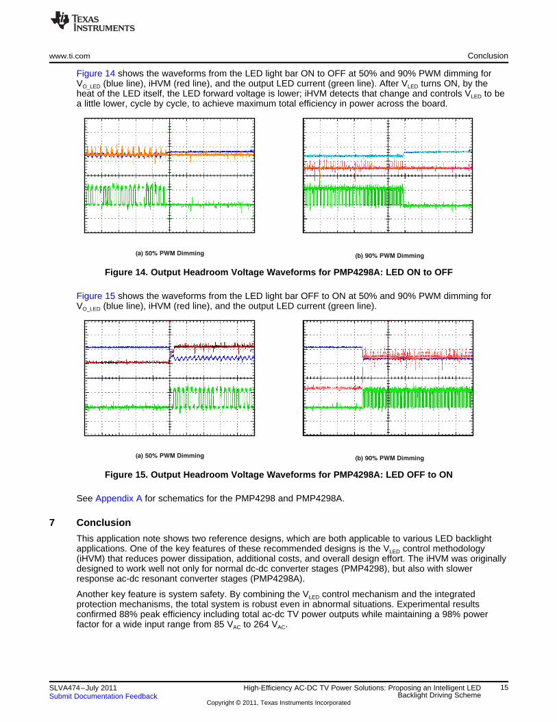
Figure 14 shows the waveforms from the LED light bar ON to OFF at 50% and 90% PWM dimming forVO_LED (blue line), iHVM (red line), and the output LED current (green line). After VLED turns ON, by theheat of the LED itself, the LED forward voltage is lower; iHVM detects that change and controls VLED to bea little lower, cycle by cycle, to achieve maximum total efficiency in power across the board.
Figure 14. Output Headroom Voltage Waveforms for PMP4298A: LED ON to OFF
Figure 15 shows the waveforms from the LED light bar OFF to ON at 50% and 90% PWM dimming forVO_LED (blue line), iHVM (red line), and the output LED current (green line).
Figure 15. Output Headroom Voltage Waveforms for PMP4298A: LED OFF to ON
See Appendix A for schematics for the PMP4298 and PMP4298A.
7 Conclusion
This application note shows two reference designs, which are both applicable to various LED backlightapplications. One of the key features of these recommended designs is the VLED control methodology(iHVM) that reduces power dissipation, additional costs, and overall design effort. The iHVM was originallydesigned to work well not only for normal dc-dc converter stages (PMP4298), but also with slowerresponse ac-dc resonant converter stages (PMP4298A).
Another key feature is system safety. By combining the VLED control mechanism and the integratedprotection mechanisms, the total system is robust even in abnormal situations. Experimental resultsconfirmed 88% peak efficiency including total ac-dc TV power outputs while maintaining a 98% powerfactor for a wide input range from 85 VAC to 264 VAC.
15SLVA474–July 2011 High-Efficiency AC-DC TV Power Solutions: Proposing an Intelligent LEDBacklight Driving SchemeSubmit Documentation Feedback
Copyright © 2011, Texas Instruments Incorporated

References www.ti.com
8 References
Unless otherwise noted, these documents are available for download through the Texas Instrumentswebsite (www.ti.com).
• TLC5960 8-channel LED driver controller with integrated intelligent thermal controller. Product datasheet. Literature number SBVS147.
• UCC28610 Green-mode flyback controller. Product data sheet. Literature number SLUS888D.• UCC25600 8-pin high-performance resonant mode controller. Product data sheet. Literature number
SLUS846A.• UCC28051 PFC controller for low to medium power applications requiring compliance with IEC
1000-3-2. Product data sheet. Literature number SLUS515F.
Appendix A Schematics
Schematics for the PMP4298 and PMP4298A are given in Figure 16 to Figure 21.
16 High-Efficiency AC-DC TV Power Solutions: Proposing an Intelligent LED SLVA474–July 2011Backlight Driving Scheme Submit Documentation Feedback
Copyright © 2011, Texas Instruments Incorporated
NL
++
>12.5
Vneeded
Chassis
85V
AC
to265V
AC
Input
+
www.ti.com Appendix A
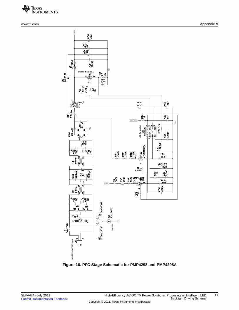
Figure 16. PFC Stage Schematic for PMP4298 and PMP4298A
17SLVA474–July 2011 High-Efficiency AC-DC TV Power Solutions: Proposing an Intelligent LEDBacklight Driving SchemeSubmit Documentation Feedback
Copyright © 2011, Texas Instruments Incorporated
+
+
+
+
Appendix A www.ti.com
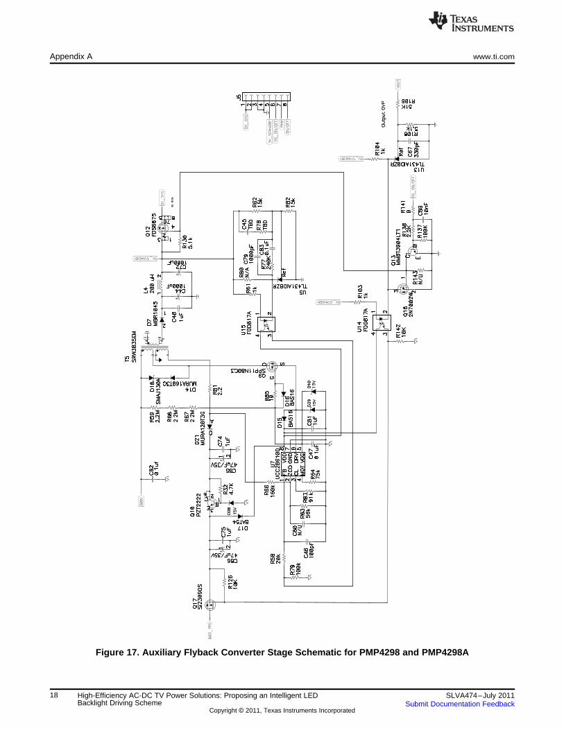
Figure 17. Auxiliary Flyback Converter Stage Schematic for PMP4298 and PMP4298A
18 High-Efficiency AC-DC TV Power Solutions: Proposing an Intelligent LED SLVA474–July 2011Backlight Driving Scheme Submit Documentation Feedback
Copyright © 2011, Texas Instruments Incorporated
R98
12
765
LM
293A
D
U1:B
R76
15K
C41
0.1
uF
D26BAS16
R74
11K
C63
.47u
BA
S16
D27
R10910K
R149
11K
3.9
kR
100
R96
220
N/AD29
23
14FO
D817A
U10
R92
12K
R133NA
NA
R102
R127
0
21+
C18560uF/35V
21+
C4
330uF
C14
0.1
uF
C33
2u2
D12
BA
S16
R84
10K
R72
10K
D13BAT54
R88
10KR107
1.8M
C438.2nF/630V
MBR20200CT D28STPS20100CT D24
C60
10nF
C65
NA
NAC78
21+
C19560uF/35V
2.2uF C21
R47
0
1uF
C52
2k
R42
5.1kR71
4.7
R131
4.7
R123
R35
10K
R73
12K
C53
0.1
uF
0.1
uF
C76
C117
0.1
uF
BA
T54
D45
R11047KNA
C51
C88
1nF
/630V
N/A
D22
Ref
U11
TL431A
IDB
ZRC69
NA
C508.2nF/630V
43K
R91
51
R128
NA
R87
21+
C3
330uF
R136
NA
21
L3
R24
12K
5.1kR13
R25
12K
R14
NT
C
1M
R75
Ref
TL431AIDBZRU6
C55
1u
1:1
:1T
1
OT
P(N
TC
on
Pri
HS
,95C
)
R34
1.1
M
2
13
8 4LM
293A
D
U1:A
Hic
cup
OC
P
1N
4148W
D35
R111
47K
1D
T2
RT
3O
C4
SS
5G
D2
6G
ND
7V
CC
8G
D1
UC
C25600D
U9
1u
C61
R95
12
R97
22k
R1121.8M
SDG
SPP20N60C3Q7
NAC42
C56
220pF
C54
2.2
nF
R89
3K
R99
24K
R135NA
C59
22nF1
.1m
H:3
00uH
T3
C49NA
4.99k
R101
10K
R94
1000pF
C57
MBR20200CT D34
C77NAR134
NA
21+
C20560uF/35V
STPS20100CT D25
2.2
uF
C73741 6 8532
J2
1N
4148W
D23
SDG
SPP20N60C3Q11
C622.2nF
+24V
@2.5
A
48V
@1.5
A
D33
BA
T54
www.ti.com Appendix A
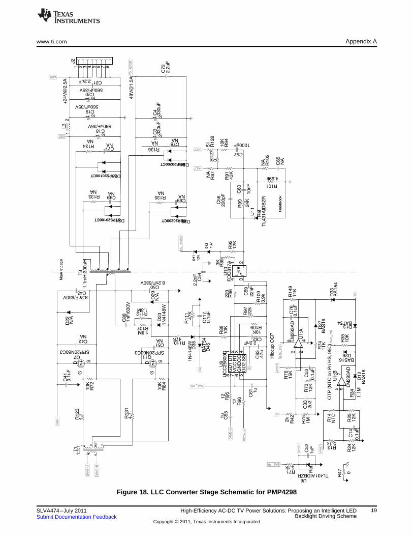
Figure 18. LLC Converter Stage Schematic for PMP4298
19SLVA474–July 2011 High-Efficiency AC-DC TV Power Solutions: Proposing an Intelligent LEDBacklight Driving SchemeSubmit Documentation Feedback
Copyright © 2011, Texas Instruments Incorporated
+
+
+
+
+
Appendix A www.ti.com
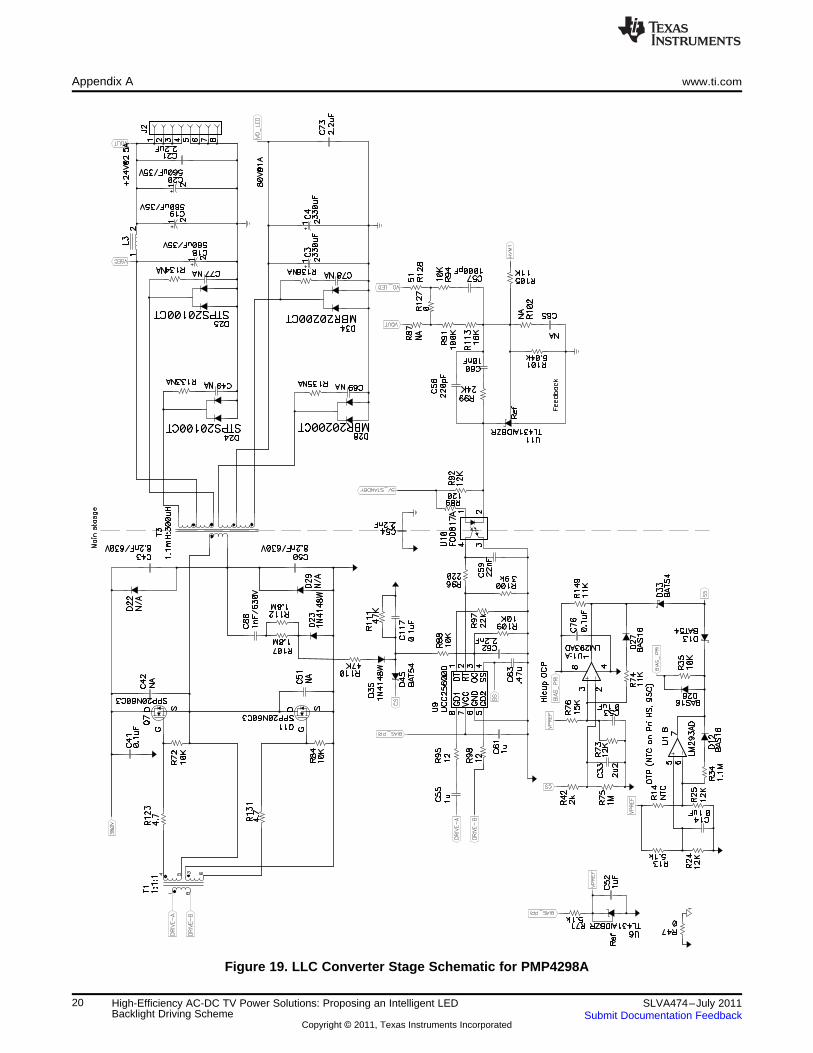
Figure 19. LLC Converter Stage Schematic for PMP4298A
20 High-Efficiency AC-DC TV Power Solutions: Proposing an Intelligent LED SLVA474–July 2011Backlight Driving Scheme Submit Documentation Feedback
Copyright © 2011, Texas Instruments Incorporated
R15100K
100KR38
R41
4.9
9
R119200K
R65100K
100K
R21
1uF
C12
0R
105
R7
3.9
R86
4.9
9
40
R8
30.1
k
R115100K
UV
LOR
930.1
k
R117
4.9
9
C10
1uF
R36200K
14
R1
10
R121100K
R44
82K
R124
4.9
9
R129200K
R93200K
21+
C6
100uF
R29optional
43
C11220pF
R116200K
MU
RA
120T
3G
D32
R37
4.9
9
1 G3
S
4D
Q2
FQ
T4N
20L
R31200K
D4
7.5
V
D3
24V
MU
RA
120T
3G
D36
R60
4.9
9
1 G3
S
4D
Q15
FQ
T4N
20L
R43100K
100K
R17
24K
R16
MU
RA
120T
3G
D38
1 G3
S
4D
Q18
FQ
T4N
20L
R90100K
1uF
C24
0.3
3uF
C23
50VR2 10
R12
0.0
30.5
W
R101k
MM
BT
2222A
Q3
R148
10K
R40
51K
80V
@1A
R26
100K
R27
100K
R22
100K
R114
4.9
9
1 G3
S
4D
FQ
T4N
20L
Q19
MU
RA
120T
3G
D2
MM
BT
2222
Q6
R118100K
1 G3
S
4D
Q21
FQ
T4N
20L
R120
4.9
9
C15470pF
R18
13K
1.5
KR
20
C13
0.1
uF
MU
RA
120T
3G
D6
0.3
3uF
C8
50V
R6
220K
2.2
uF
C17
100V
21+
C16
330uF
220pF
C9
R122200K
R125100K
1 G3
S
4D
Q22
FQ
T4N
20L
R70200K
MU
RA
120T
3G
D31
2147uH
L1
21+
100uF
C5
MB
R10H
100C
T
D1
SDG
IPP80CN10NQ1
MM
BT
2907
Q4
R39
100
R30optional
R28
100K
2.2
uF
C1
100V
21+
C7
100uF
R23
390K
18
G4
15
G3
12
G2
9G
1
63
21
G8
24
G7
27
G6
30
G5
36
19
S4
16
S3
13
S2
17
D4
14
D3
7 8
10
S1
11
D2
1 52
20
S8
23
S7
26
S6
22
D8
25
D7
29
S5
32
XF
LT
28
D6
31
D5
38
34
37
4H
VM
1/H
VM
35
HV
M4/R
EF
LS
D
33
TLC
596xD
AU
4
MU
RA
120T
3G
D37
1 G3
S
4D
Q5
FQ
T4N
20L
100K
R3
1 G3
S
4D
Q20
FQ
T4N
20L
MU
RA
120T
3G
D30
741 6 8532
J3
741 6 8532
J4
www.ti.com Appendix A
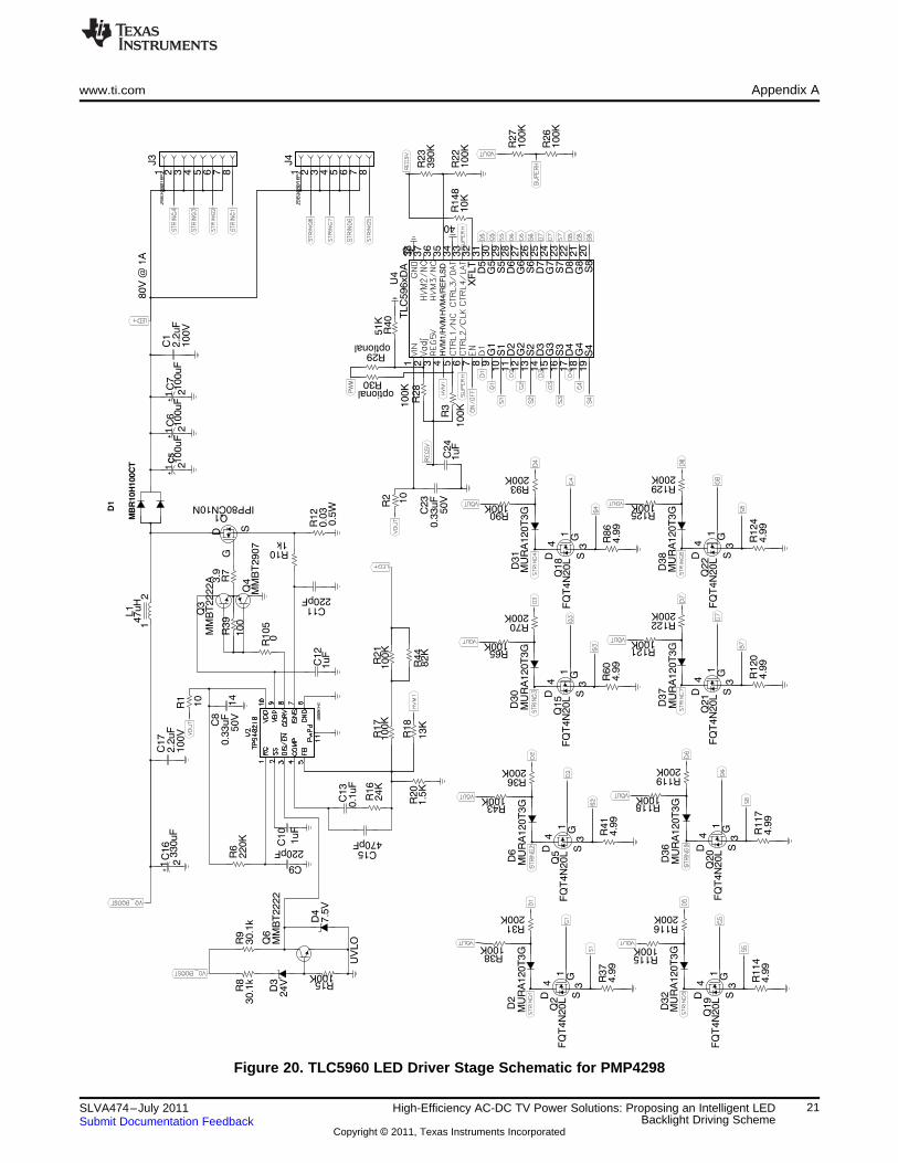
Figure 20. TLC5960 LED Driver Stage Schematic for PMP4298
21SLVA474–July 2011 High-Efficiency AC-DC TV Power Solutions: Proposing an Intelligent LEDBacklight Driving SchemeSubmit Documentation Feedback
Copyright © 2011, Texas Instruments Incorporated
++
+
Appendix A www.ti.com
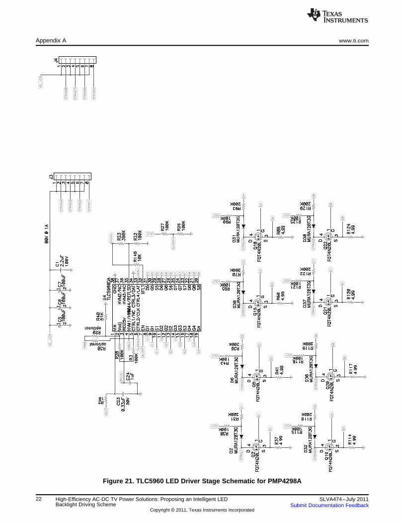
Figure 21. TLC5960 LED Driver Stage Schematic for PMP4298A
22 High-Efficiency AC-DC TV Power Solutions: Proposing an Intelligent LED SLVA474–July 2011Backlight Driving Scheme Submit Documentation Feedback
Copyright © 2011, Texas Instruments Incorporated

IMPORTANT NOTICE
Texas Instruments Incorporated and its subsidiaries (TI) reserve the right to make corrections, modifications, enhancements, improvements,and other changes to its products and services at any time and to discontinue any product or service without notice. Customers shouldobtain the latest relevant information before placing orders and should verify that such information is current and complete. All products aresold subject to TI’s terms and conditions of sale supplied at the time of order acknowledgment.
TI warrants performance of its hardware products to the specifications applicable at the time of sale in accordance with TI’s standardwarranty. Testing and other quality control techniques are used to the extent TI deems necessary to support this warranty. Except wheremandated by government requirements, testing of all parameters of each product is not necessarily performed.
TI assumes no liability for applications assistance or customer product design. Customers are responsible for their products andapplications using TI components. To minimize the risks associated with customer products and applications, customers should provideadequate design and operating safeguards.
TI does not warrant or represent that any license, either express or implied, is granted under any TI patent right, copyright, mask work right,or other TI intellectual property right relating to any combination, machine, or process in which TI products or services are used. Informationpublished by TI regarding third-party products or services does not constitute a license from TI to use such products or services or awarranty or endorsement thereof. Use of such information may require a license from a third party under the patents or other intellectualproperty of the third party, or a license from TI under the patents or other intellectual property of TI.
Reproduction of TI information in TI data books or data sheets is permissible only if reproduction is without alteration and is accompaniedby all associated warranties, conditions, limitations, and notices. Reproduction of this information with alteration is an unfair and deceptivebusiness practice. TI is not responsible or liable for such altered documentation. Information of third parties may be subject to additionalrestrictions.
Resale of TI products or services with statements different from or beyond the parameters stated by TI for that product or service voids allexpress and any implied warranties for the associated TI product or service and is an unfair and deceptive business practice. TI is notresponsible or liable for any such statements.
TI products are not authorized for use in safety-critical applications (such as life support) where a failure of the TI product would reasonablybe expected to cause severe personal injury or death, unless officers of the parties have executed an agreement specifically governingsuch use. Buyers represent that they have all necessary expertise in the safety and regulatory ramifications of their applications, andacknowledge and agree that they are solely responsible for all legal, regulatory and safety-related requirements concerning their productsand any use of TI products in such safety-critical applications, notwithstanding any applications-related information or support that may beprovided by TI. Further, Buyers must fully indemnify TI and its representatives against any damages arising out of the use of TI products insuch safety-critical applications.
TI products are neither designed nor intended for use in military/aerospace applications or environments unless the TI products arespecifically designated by TI as military-grade or "enhanced plastic." Only products designated by TI as military-grade meet militaryspecifications. Buyers acknowledge and agree that any such use of TI products which TI has not designated as military-grade is solely atthe Buyer's risk, and that they are solely responsible for compliance with all legal and regulatory requirements in connection with such use.
TI products are neither designed nor intended for use in automotive applications or environments unless the specific TI products aredesignated by TI as compliant with ISO/TS 16949 requirements. Buyers acknowledge and agree that, if they use any non-designatedproducts in automotive applications, TI will not be responsible for any failure to meet such requirements.
Following are URLs where you can obtain information on other Texas Instruments products and application solutions:
Products Applications
Audio www.ti.com/audio Communications and Telecom www.ti.com/communications
Amplifiers amplifier.ti.com Computers and Peripherals www.ti.com/computers
Data Converters dataconverter.ti.com Consumer Electronics www.ti.com/consumer-apps
DLP® Products www.dlp.com Energy and Lighting www.ti.com/energy
DSP dsp.ti.com Industrial www.ti.com/industrial
Clocks and Timers www.ti.com/clocks Medical www.ti.com/medical
Interface interface.ti.com Security www.ti.com/security
Logic logic.ti.com Space, Avionics and Defense www.ti.com/space-avionics-defense
Power Mgmt power.ti.com Transportation and www.ti.com/automotiveAutomotive
Microcontrollers microcontroller.ti.com Video and Imaging www.ti.com/video
RFID www.ti-rfid.com Wireless www.ti.com/wireless-apps
RF/IF and ZigBee® Solutions www.ti.com/lprf
TI E2E Community Home Page e2e.ti.com
Mailing Address: Texas Instruments, Post Office Box 655303, Dallas, Texas 75265Copyright © 2011, Texas Instruments Incorporated