Embed Size (px)
Citation preview

HIGH&EXTRA-HIGH VOLTAGEUNDERGROUND SOLUTIONS
North America

WELCOME
Contact Us
On-Line Catalog Features
•Viewthecataloginfullscreenmodebyusingthefarleftexpansionlogoonthemenubar.(Keyboardinputmaynotworkinfullscreenmode,whichmeansyoumustleavethefullscreenmodeinordertoutilizetheemailfunction.)
•Clickthe“GeneralCable”logoontheleftsideofthemenubartogotoGeneralCable’sWebsite.
•The“ProductSelectionLocator”or“TableofContents”buttoninthecenterofthemenubartakesyoutoafullyinteractivepage.Clickonanyproductcategoryorlistingtotakeyoutotheappropriatepage.(Allotherpagereferencesthroughoutthecatalogarealsofullyinteractive.)
•Theentirecatalog’scontentscanbesearchedusingtheSearchbuttonlocatedintheupperrightofthemenubar.
•Turncatalogpagesbyclickingyourmouseonthetoporbottomcornerofthepageorbyusingtheforwardorbackarrowsonthesideofthepageoronthebottombar.
•Zoomtodetailsoneachpagebyclickingwhenthemagnifyingglasspointerisactive.Clickagaintoreturntofullview.
•Sharethecompleteinteractivecatalogbyselectingthe“SharethisPublication”iconlocatedinthelowerrightonthebottombar.
•PrintallorselectedpagesusingthePrinticonlocatedinthelowerrightonthebottombar.
•TheentireinteractivecatalogorindividualpagescanbedownloadedasaPDFusingthePDFiconlocatedinthelowerrightonthebottombar.
•Use“Croppartofpage”iconlocatedinthelowerrightonthebottombartotakeasnapshotofanypartofapageandsaveasajpg.
General Cable Website
Join the Wire Wizard for a quick, informative tour showing the interactive features of our catalogs

2
ONE COMPANY -CONNECTING THE WORLD
General Cable
POWERFUL PRESENCE · PRODUCTS · PERFORMANCE · PEOPLE
With more than 11,000 associates on six continents, General Cable is a global leader in the development, design, manufacture, marketing and distribution of copper, aluminium and fibre optic wire and cable products for the energy, industrial, specialty and communications markets.
We are one of the largest wire and cable manufacturers in the world and hold increasing share in both established and growing markets.
General Cable serves its customers through a global network of manufacturing facilities with worldwide sales representation and distribution. With a portfolio of more than 100,000 products to meet thousands of diverse applications requirements, we continue to invest in research and development in order to maintain and extend our technology leadership, developing new materials, designing new products, and creating new solutions to meet tomorrow’s market challenges.
In every sector and everywhere, we are strongly positioned to help our partners achieve their objectives.
We offer our customers all the strengths and value of a large company, but our people give us the agility and responsiveness of a small one. We can service you globally or locally.
General Cable
SUMMARY
04 INTRODUCTION
09 CABLES
10 Assumptions to Calculate the Transmission Capacity
11 Welded Aluminium Sheath
15 Copper Wires with Lead Sheath
19 Copper Wires with Aluminium Laminated Foil
23 USER’S GUIDE
29 ACCESSORIES
41 SERVICES
47 STAND-BY LINKS

4
General Cable
INTRODUCTION
A WORLDWIDE HIGH-VOLTAGE LEADER
General Cable’s Silec Brand underground transmission cabling solutions have been a recognized leader in the global electric utility market for almost half a century. With unrivalled expertise and turnkey project management, General Cable provides the innovation, quality and service to transmit power reliably and cost-effectively from production to consumption areas, from one national grid to another. With Silec solid-dielectric extruded high-and extra-high-voltage (HV/EHV) cable systems, General Cable provides its global customers with superior cable system solutions that offer maximum flexibility and service life.
» Decades of experience in underground solid-dielectric cable systems» Comprehensive line of high-and extra-high-voltage cable and accessories» Total turnkey project management from planning through installation, testing and commissioning» Optimized economics to keep projects on time and on budget» Extremely reliable, low-maintenance and long-term performance» Complete post-project maintenance services and responsive ongoing support

General Cable
5
RELY ON OUR EXPERIENCE… EXPERIENCE OUR CAPABILITIES
World leadership for HV/EHV underground transmission cable systems up to 500 kV
40 YEARS OF WORLDWIDE HIGH-& EXTRA-HIGH-VOLTAGE FIRSTS
Voltage level 63-161kV 220-230kV 330-500kVCable 9,947 km 4,135 km 372 kmTerminations 22,273 7,508 849Joints 11,215 6,561 450Ref. 2010
63-110 kV132-160 kV230 kV345-500 kV
Ref. 2010
34 km158 terminations1 joint
338 km691 terminations449 joints
4,185 km7,508 terminations6,561 joints
4,849 km8,215 terminations4,672 joints
5,098 km14,058 terminations6,543 joints
First worldwideapplication
VOLTAGE RANGE
6
General Cable
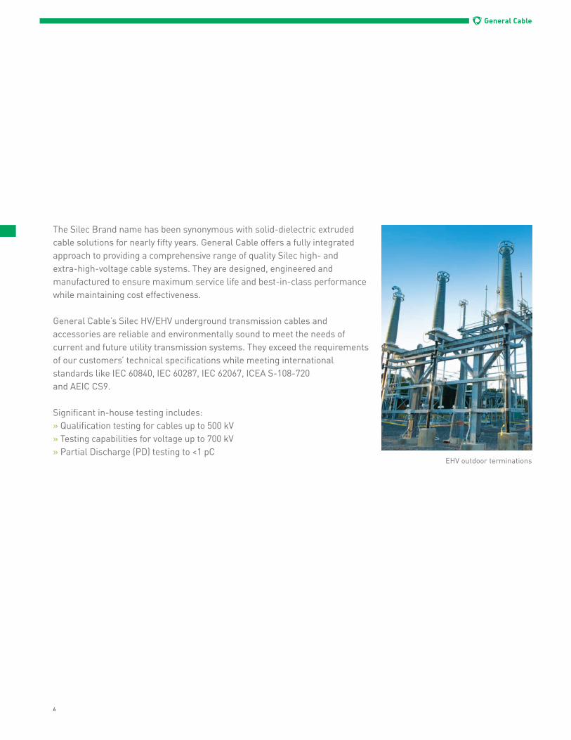
The Silec Brand name has been synonymous with solid-dielectric extruded cable solutions for nearly fifty years. General Cable offers a fully integrated approach to providing a comprehensive range of quality Silec high- and extra-high-voltage cable systems. They are designed, engineered and manufactured to ensure maximum service life and best-in-class performance while maintaining cost effectiveness. General Cable’s Silec HV/EHV underground transmission cables and accessories are reliable and environmentally sound to meet the needs of current and future utility transmission systems. They exceed the requirements of our customers’ technical specifications while meeting international standards like IEC 60840, IEC 60287, IEC 62067, ICEA S-108-720and AEIC CS9.
Significant in-house testing includes:» Qualification testing for cables up to 500 kV» Testing capabilities for voltage up to 700 kV» Partial Discharge (PD) testing to <1 pC
EHV outdoor terminations
7
General Cable
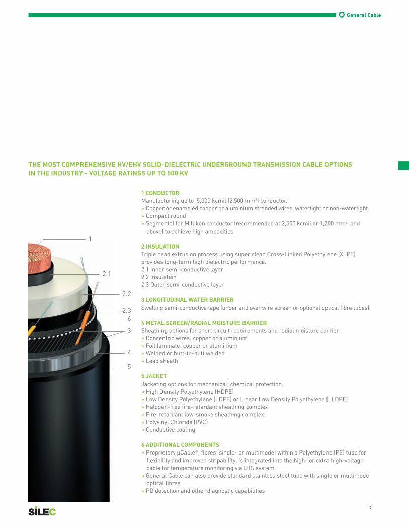
THE MOST COMPREHENSIVE HV/EHV SOLID-DIELECTRIC UNDERGROUND TRANSMISSION CABLE OPTIONS IN THE INDUSTRY - VOLTAGE RATINGS UP TO 500 KV
1 CONDUCTOR Manufacturing up to 5,000 kcmil (2,500 mm2) conductor.» Copper or enameled copper or aluminium stranded wires, watertight or non-watertight» Compact round» Segmental for Milliken conductor (recommended at 2,500 kcmil or 1,200 mm2 and
above) to achieve high ampacities
2 INSULATIONTriple head extrusion process using super clean Cross-Linked Polyethylene (XLPE) provides long-term high dielectric performance. 2.1 Inner semi-conductive layer2.2 Insulation2.3 Outer semi-conductive layer
3 LONGITUDINAL WATER BARRIERSwelling semi-conductive tape (under and over wire screen or optional optical fibre tubes).
4 METAL SCREEN/RADIAL MOISTURE BARRIERSheathing options for short circuit requirements and radial moisture barrier.» Concentric wires: copper or aluminium» Foil laminate: copper or aluminium» Welded or butt-to-butt welded» Lead sheath
5 JACKETJacketing options for mechanical, chemical protection.» High Density Polyethylene (HDPE)» Low Density Polyethylene (LDPE) or Linear Low Density Polyethylene (LLDPE)» Halogen-free fire-retardant sheathing complex» Fire-retardant low-smoke sheathing complex» Polyvinyl Chloride (PVC)» Conductive coating
6 ADDITIONAL COMPONENTS» Proprietary µCable®, fibres (single- or multimode) within a Polyethylene (PE) tube for
flexibility and improved stripability, is integrated into the high- or extra high-voltage cable for temperature monitoring via DTS system
» General Cable can also provide standard stainless steel tube with single or multimode optical fibres
» PD detection and other diagnostic capabilities

General Cable
8
HIGH-& EXTRA-HIGH-VOLTAGE CABLE ACCESSORIES
As part of the fully integrated approach and commitment to providing complete system performance, General Cable offers a wide range of Silec HV/EHV cable accessories. Vital components of an overall cable system, these accessories are designed, manufactured and precision-controlled to ensure best-in-class performance and long-term service reliability.
A COMPLETE RANGE OF HIGH-AND EXTRA-HIGH-VOLTAGE CABLE ACCESSORIES From 72.5 kV to 550 kV to connect cables up to 2,500mm2
Silec Brand’s advanced technology in compounding and moulding of silicone, EPDM and resins translates into a complete range of high-performance accessories, from 72.5 kV to 550 kV to connect cables up to 5,000 kcmil (2,500 mm2) per IEC 60840, IEC 62067, IEEE 48, IEEE 404, ICEA S-108-720 and AEIC CS9.
Silec HV/EHV cable accessories are 100% validated through a range of calculation, modelling and testing techniques that enable General Cable to continuously adapt and optimize performance to meet the demands of our customers. General Cable offers an engineered short joint that is more space-efficient and affordable. We also provide outdoor terminations filled with ester oil, which improves on-site safety conditions and shortens installation time. With kitting options and superior logistics and distribution, General Cable ensures that our customers receive the accessories they need in days, not weeks or months.
HIGH-& EXTRA-HIGH-VOLTAGE TURNKEY SERVICES
With more than 14,000 km of cables, 30,000 terminations and 18,000 joints installed and commissioned since 1962, General Cable’s Silec underground cabling solutions are your best partner for the life of the entire cable system. From system engineering and installation to final testing and post-project services, General Cable specializes in providing turnkey service management for new cable projects or the upgrading of existing cable circuits.
With decades of experience, General Cable’s HV/EHV specialists design, install and manage cable systems according to customer specifications, budgets and deadlines. We then provide the comprehensive assessment, monitoring, training and service programmes needed to extend the lifetime of the system, while at the same time reducing maintenance and optimizing operating costs.
General Cable on-site testing truck
10
General Cable
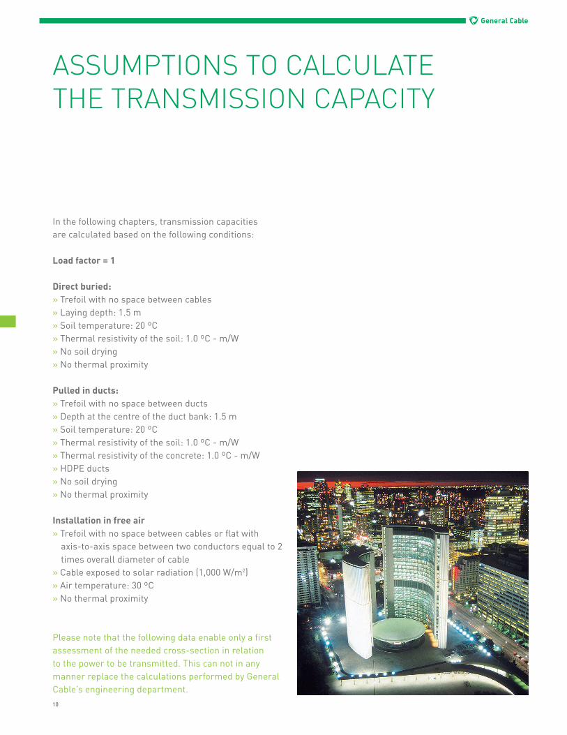
In the following chapters, transmission capacitiesare calculated based on the following conditions:
Load factor = 1
Direct buried:» Trefoil with no space between cables» Laying depth: 1.5 m» Soil temperature: 20 ºC» Thermal resistivity of the soil: 1.0 ºC - m/W» No soil drying» No thermal proximity
Pulled in ducts:» Trefoil with no space between ducts» Depth at the centre of the duct bank: 1.5 m» Soil temperature: 20 ºC» Thermal resistivity of the soil: 1.0 ºC - m/W» Thermal resistivity of the concrete: 1.0 ºC - m/W» HDPE ducts» No soil drying» No thermal proximity
Installation in free air» Trefoil with no space between cables or flat with
axis-to-axis space between two conductors equal to 2 times overall diameter of cable
» Cable exposed to solar radiation (1,000 W/m2)» Air temperature: 30 ºC» No thermal proximity
Please note that the following data enable only a first assessment of the needed cross-section in relation to the power to be transmitted. This can not in any manner replace the calculations performed by General Cable’s engineering department.
ASSUMPTIONS TO CALCULATETHE TRANSMISSION CAPACITY
11
General Cable
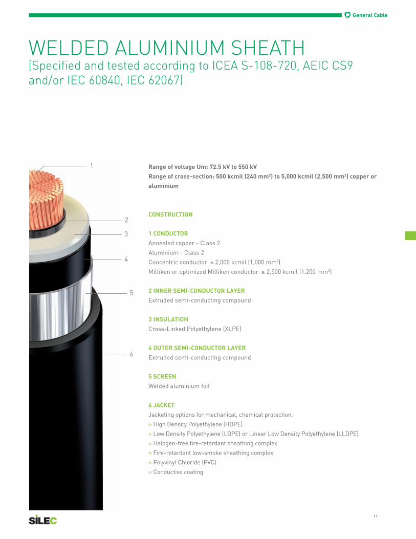
Range of voltage Um: 72.5 kV to 550 kV
Range of cross-section: 500 kcmil (240 mm2) to 5,000 kcmil (2,500 mm2) copper or
aluminium
CONSTRUCTION
1 CONDUCTOR
Annealed copper - Class 2
Aluminium - Class 2
Concentric conductor ≤ 2,000 kcmil (1,000 mm2)
Milliken or optimized Milliken conductor ≥ 2,500 kcmil (1,200 mm2)
2 INNER SEMI-CONDUCTOR LAYER
Extruded semi-conducting compound
3 INSULATION
Cross-Linked Polyethylene (XLPE)
4 OUTER SEMI-CONDUCTOR LAYER
Extruded semi-conducting compound
5 SCREEN
Welded aluminium foil
6 JACKET
Jacketing options for mechanical, chemical protection.
» High Density Polyethylene (HDPE)
» Low Density Polyethylene (LDPE) or Linear Low Density Polyethylene (LLDPE)
» Halogen-free fire-retardant sheathing complex
» Fire-retardant low-smoke sheathing complex
» Polyvinyl Chloride (PVC)
» Conductive coating
WELDED ALUMINIUM SHEATH(Specified and tested according to ICEA S-108-720, AEIC CS9 and/or IEC 60840, IEC 62067)

12
General Cable
500 2.31 3.84 0.022 0.028 0.075 538 541 590 612 493 417 553 532750 2.53 4.87 0.015 0.020 0.085 652 658 733 761 581 472 672 633
1000 2.73 5.87 0.011 0.015 0.095 765 773 880 915 659 518 785 7231250 2.90 6.95 0.009 0.012 0.105 857 870 1002 1042 718 552 874 7891500 3.04 7.85 0.007 0.010 0.110 927 945 1100 1145 762 579 945 8431750 3.18 8.90 0.007 0.010 0.120 988 1013 1191 1242 796 601 1007 8862000 3.28 9.85 0.005 0.008 0.125 1043 1073 1271 1325 821 617 1053 9182500 3.55 11.90 0.004 0.006 0.140 1267 1278 1570 1638 936 672 1236 10393000 3.73 13.71 0.004 0.005 0.145 1377 1394 1733 1810 985 706 1329 10993500 3.89 15.25 0.003 0.005 0.150 1468 1493 1875 1958 1018 730 1399 11444000 4.03 16.98 0.003 0.004 0.160 1552 1584 2000 2091 1039 747 1449 1168
Sectionskcmil
Overaldiameter
InchesWeight
lb/ft
DCconductorresistance
at 20 ºCΩ/1000 ft
ACapparentconductorresistance
at 90 ºC Ω/1000 ft
CapacitanceµF/1000 ft
Directburied
Pulledin ducts(Trefoil)
In air,trefoil
Exposed to solarradiation (*)
In air,flat
Exposed to solarradiation (*)
Directburied
Pulledin ducts (Trefoil)
In air,trefoil
Exposed to solarradiation (*)
In air,flat
Exposed to solarradiation (*)
CONTINUOUS CURRENT RATING, AEarthing at one point
CONTINUOUS CURRENT RATING, A Earthing in several points
Um = 72.5 kV (copper conductors)
Um = 145 kV (copper conductors)
(*) Without exposure to direct solar radiation, we consider the ampacity is about 20% higher
WELDED ALUMINIUM SHEATH
500 2.89 4.38 0.022 0.028 0.055 519 536 572 584 481 428 543 527750 2.98 5.25 0.015 0.020 0.060 624 651 705 716 564 485 658 625
1000 3.14 6.23 0.011 0.015 0.065 718 759 831 838 635 534 761 7101250 3.26 7.00 0.009 0.012 0.070 795 852 936 940 689 567 845 7741500 3.43 8.21 0.007 0.010 0.075 853 921 1019 1018 730 594 911 8261750 3.56 9.24 0.007 0.010 0.080 860 927 1041 1041 739 602 934 8462000 3.65 10.17 0.005 0.008 0.080 945 1038 1161 1153 789 634 1018 9042500 3.93 12.36 0.004 0.006 0.090 1104 1215 1392 1362 837 681 1128 10013000 4.10 14.17 0.004 0.005 0.095 1182 1313 1519 1477 880 710 1210 10603500 4.29 15.84 0.003 0.005 0.100 1234 1472 1616 1557 900 711 1263 11004000 4.42 17.50 0.003 0.004 0.100 1277 1549 1697 1623 916 729 1300 11355000 4.69 21.08 0.002 0.003 0.110 1346 1677 1841 1737 941 758 1381 1193
Sectionskcmil
Overaldiameter
InchesWeight
lb/ft
DCconductorresistance
at 20 ºCΩ/1000 ft
ACapparentconductorresistance
at 90 ºC Ω/1000 ft
CapacitanceµF/1000 ft
Directburied
Pulledin ducts(Trefoil)
In air,trefoil
Exposed to solarradiation (*)
In air,flat
Exposed to solarradiation (*)
Directburied
Pulledin ducts (Trefoil)
In air,trefoil
Exposed to solarradiation (*)
In air,flat
Exposed to solarradiation (*)
CONTINUOUS CURRENT RATING, AEarthing at one point
CONTINUOUS CURRENT RATING, A Earthing in several points

13
General Cable
(*) Without exposure to direct solar radiation, we consider the ampacity is about 20% higher
WELDED ALUMINIUM SHEATH
Um = 245 kV (copper conductors)
1000 3.59 6.99 0.011 0.015 0.050 707 741 813 818 628 548 753 7151250 3.75 8.00 0.009 0.012 0.050 782 829 915 915 678 586 834 7811500 3.88 9.01 0.007 0.010 0.055 838 895 996 993 718 614 900 8341750 4.02 10.02 0.006 0.009 0.060 887 953 1072 1064 752 636 960 8802000 4.14 11.03 0.005 0.008 0.060 927 1054 1134 1120 778 654 1008 9192500 4.39 13.11 0.004 0.006 0.065 1076 1240 1355 1315 867 701 1167 10323000 4.57 14.92 0.004 0.005 0.065 1151 1345 1479 1430 912 723 1255 10893500 4.77 16.74 0.003 0.004 0.070 1201 1426 1574 1508 938 747 1319 11384000 4.89 18.35 0.003 0.004 0.075 1260 1506 1670 1596 974 760 1386 11765000 5.18 22.05 0.003 0.004 0.080 1279 1524 1718 1637 993 791 1430 1219
Sectionskcmil
Overaldiameter
InchesWeight
lb/ft
DCconductorresistance
at 20 ºCΩ/1000 ft
ACapparentconductorresistance
at 90 ºC Ω/1000 ft
CapacitanceµF/1000 ft
Directburied
Pulledin ducts(Trefoil)
In air,trefoil
Exposed to solarradiation (*)
In air,flat
Exposed to solarradiation (*)
Directburied
Pulledin ducts (Trefoil)
In air,trefoil
Exposed to solarradiation (*)
In air,flat
Exposed to solarradiation (*)
CONTINUOUS CURRENT RATING, AEarthing at one point
CONTINUOUS CURRENT RATING, A Earthing in several points
Um = 362 kV (copper conductors)
1000 3.74 7.32 0.0110 0.0148 0.046 694 727 802 814 617 546 745 7201250 3.82 8.33 0.0086 0.0120 0.049 767 813 904 912 667 584 826 7881500 4.00 9.36 0.0072 0.0105 0.052 818 873 980 985 702 609 888 8401750 4.00 10.43 0.0061 0.0094 0.055 865 928 1053 1055 734 623 946 8862000 4.23 11.24 0.0053 0.0085 0.058 902 979 1117 1115 756 645 992 9202500 4.45 13.27 0.0044 0.0059 0.061 1043 1140 1329 1305 840 697 1144 10323000 4.72 15.21 0.0036 0.0050 0.061 1103 1214 1439 1399 877 734 1226 11003500 4.96 17.00 0.0031 0.0045 0.064 1160 1279 1539 1481 909 754 1248 11464000 5.00 18.00 0.0027 0.0041 0.070 1284 1582 1686 1610 920 815 1296 12675000 5.38 22.67 0.0021 0.0035 0.076 1362 1707 1837 1737 931 841 1379 1341
Sectionskcmil
Overaldiameter
InchesWeight
lb/ft
DCconductorresistance
at 20 ºCΩ/1000 ft
ACapparentconductorresistance
at 90 ºC Ω/1000 ft
CapacitanceµF/1000 ft
Directburied
Pulledin ducts(Trefoil)
In air,trefoil
Exposed to solarradiation (*)
In air,flat
Exposed to solarradiation (*)
Directburied
Pulledin ducts (Trefoil)
In air,trefoil
Exposed to solarradiation (*)
In air,flat
Exposed to solarradiation (*)
CONTINUOUS CURRENT RATING, AEarthing at one point
CONTINUOUS CURRENT RATING, A Earthing in several points

14
General Cable
400 4.39 7.52 0.0143 0.0616 0.040 638 668 694 705 577 544 658 669500 4.39 8.12 0.0112 0.0488 0.040 719 761 803 812 635 590 749 759630 4.38 8.79 0.0086 0.0389 0.045 803 863 917 922 690 633 839 846800 4.39 9.80 0.0067 0.0317 0.050 885 967 1038 1036 740 672 929 932
1000 4.63 11.61 0.0054 0.0234 0.055 1013 1121 1233 1215 782 725 1040 10361200 4.75 12.88 0.0046 0.0204 0.055 1078 1200 1334 1307 813 747 1103 10931600 5.46 18.38 0.0034 0.0159 0.060 1192 1425 1517 1469 864 789 1213 11932000 5.28 19.86 0.0027 0.0133 0.065 1279 1555 1672 1603 902 819 1303 12762500 5.58 23.55 0.0022 0.0113 0.070 1362 1674 1827 1736 936 846 1390 1353
Sectionsmm2
Overaldiameter
InchesWeight
lb/ft
DCconductorresistance
at 20 ºCΩ/1000 ft
ACapparentconductorresistance
at 90 ºC Ω/1000 ft
CapacitanceµF/1000 ft
Directburied
Pulledin ducts(Trefoil)
In air,trefoil
Exposed to solarradiation (*)
In air,flat
Exposed to solarradiation (*)
Directburied
Pulledin ducts (Trefoil)
In air,trefoil
Exposed to solarradiation (*)
In air,flat
Exposed to solarradiation (*)
CONTINUOUS CURRENT RATING, AEarthing at one point
CONTINUOUS CURRENT RATING, A Earthing in several points
Um = 420 kV (copper conductors) - Maximum single-phase short-circuit = 63 kA - 1 s
Um = 550 kV (copper conductors) - Maximum single-phase short-circuit = 63 kA - 1 s
(*) Without exposure to direct solar radiation, we consider the ampacity is about 20% higher
400 4.63 8.19 0.0143 0.0615 0.040 632 659 686 697 573 544 652 665500 4.59 8.59 0.0112 0.0488 0.040 711 751 794 803 630 591 743 755630 4.59 9.40 0.0086 0.0388 0.040 795 850 906 912 686 634 833 842800 4.71 12.61 0.0067 0.0316 0.050 875 949 1024 1023 737 676 925 932
1000 5.04 12.88 0.0054 0.0234 0.050 1006 1146 1214 1201 784 730 1039 10371200 5.20 14.29 0.0046 0.0203 0.050 1066 1228 1310 1287 814 759 1104 11001600 5.52 18.45 0.0034 0.0158 0.055 1180 1387 1492 1449 866 799 1217 12042000 5.71 21.40 0.0027 0.0132 0.055 1270 1511 1649 1588 904 828 1310 12882500 6.01 25.16 0.0022 0.0113 0.060 1352 1623 1804 1722 938 856 1399 1368
Sectionsmm2
Overaldiameter
InchesWeight
lb/ft
DCconductorresistance
at 20 ºCΩ/1000 ft
ACapparentconductorresistance
at 90 ºC Ω/1000 ft
CapacitanceµF/1000 ft
Directburied
Pulledin ducts(Trefoil)
In air,trefoil
Exposed to solarradiation (*)
In air,flat
Exposed to solarradiation (*)
Directburied
Pulledin ducts (Trefoil)
In air,trefoil
Exposed to solarradiation (*)
In air,flat
Exposed to solarradiation (*)
CONTINUOUS CURRENT RATING, AEarthing at one point
CONTINUOUS CURRENT RATING, A Earthing in several points
WELDED ALUMINIUM SHEATH

15
General Cable
Range of voltage Um: 72.5 kV to 550 kV
Range of cross-section: 500 kcmil (240 mm2) to 5,000 kcmil (2,500 mm2) copper or
aluminium
CONSTRUCTION
1 CONDUCTOR
Annealed copper - Class 2
Aluminium - Class 2
Concentric conductor ≤ 2,000 kcmil (1,000 mm2)
Milliken or optimized Milliken conductor ≥ 2,500 kcmil (1,200 mm2)
2 INNER SEMI-CONDUCTOR LAYER
Extruded semi-conducting compound
3 INSULATION
Cross-Linked Polyethylene (XLPE)
4 OUTER SEMI-CONDUCTOR LAYER
Extruded semi-conducting compound
5 SCREEN
Copper wires and lead sheath
Optional: aluminum wires and lead sheath
6 JACKET
Jacketing options for mechanical, chemical protection.
» High Density Polyethylene (HDPE)
» Low Density Polyethylene (LDPE) or Linear Low Density Polyethylene (LLDPE)
» Halogen-free fire-retardant sheathing complex
» Fire-retardant low-smoke sheathing complex
» Polyvinyl Chloride (PVC)
» Conductive coating
COPPER WIRES WITHLEAD SHEATH(Specified and tested according to ICEA S-108-720, AEIC CS9 and/or IEC 60840, IEC 62067)

16
General Cable
COPPER WIRES WITH LEAD SHEATH
Um = 72,5 kV (copper conductors)
(*) Without exposure to direct solar radiation, we consider the ampacity is about 20% higher
500 2.89 10.81 0.022 0.028 0.075 544 545 603 626 494 423 562 542750 3.09 12.24 0.015 0.020 0.085 661 663 751 780 582 477 682 642
1000 3.19 13.33 0.011 0.015 0.095 772 777 896 931 659 524 795 7331250 3.33 14.62 0.009 0.012 0.105 866 875 1020 1061 720 559 887 8031500 3.47 16.50 0.007 0.010 0.110 935 950 1120 1167 763 586 959 8561750 3.73 19.16 0.007 0.010 0.120 998 1017 1213 1264 801 610 1025 9062000 3.92 21.32 0.005 0.008 0.125 1054 1078 1295 1350 835 631 1081 9462500 4.08 23.39 0.004 0.006 0.140 1276 1283 1595 1665 948 687 1264 10653000 4.21 25.10 0.004 0.005 0.145 1388 1399 1761 1839 1006 728 1368 11363500 4.08 23.39 0.003 0.005 0.150 1481 1499 1905 1991 1049 758 1452 11904000 4.21 25.10 0.003 0.004 0.160 1567 1596 2033 2125 1092 788 1528 1242
Sectionskcmil
Overaldiameter
InchesWeight
lb/ft
DCconductorresistance
at 20 ºCΩ/1000 ft
ACapparentconductorresistance
at 90 ºC Ω/1000 ft
CapacitanceµF/1000 ft
Directburied
Pulledin ducts(Trefoil)
In air,trefoil
Exposed to solarradiation (*)
In air,flat
Exposed to solarradiation (*)
Directburied
Pulledin ducts (Trefoil)
In air,trefoil
Exposed to solarradiation (*)
In air,flat
Exposed to solarradiation (*)
CONTINUOUS CURRENT RATING, AEarthing at one point
CONTINUOUS CURRENT RATING, A Earthing in several points
Um = 145 kV (copper conductors)
500 3.03 10.30 0.022 0.028 0.055 539 557 594 616 485 436 552 535750 3.13 11.38 0.015 0.020 0.060 655 679 739 767 568 492 669 635
1000 3.27 12.52 0.011 0.015 0.065 764 795 877 910 642 534 776 7211250 3.40 13.74 0.009 0.012 0.070 857 895 997 1036 699 566 862 7881500 3.60 15.95 0.007 0.010 0.075 927 972 1093 1136 741 591 932 8401750 3.77 17.98 0.006 0.009 0.080 990 1042 1183 1231 777 613 994 8882000 3.84 18.40 0.005 0.008 0.080 1045 1106 1263 1314 808 629 1048 9272500 4.11 21.16 0.004 0.006 0.090 1265 1309 1548 1612 911 677 1218 10413000 4.29 23.36 0.004 0.005 0.095 1375 1429 1710 1782 963 704 1313 11033500 4.49 25.48 0.003 0.005 0.100 1466 1529 1847 1927 1001 727 1390 11534000 4.61 27.36 0.003 0.004 0.100 1551 1622 1969 2054 1042 751 1464 13895000 4.88 31.53 0.002 0.003 0.110 1697 1787 2198 2296 1100 789 1585 1280
Sectionskcmil
Overaldiameter
InchesWeight
lb/ft
DCconductorresistance
at 20 ºCΩ/1000 ft
ACapparentconductorresistance
at 90 ºC Ω/1000 ft
CapacitanceµF/1000 ft
Directburied
Pulledin ducts(Trefoil)
In air,trefoil
Exposed to solarradiation (*)
In air,flat
Exposed to solarradiation (*)
Directburied
Pulledin ducts (Trefoil)
In air,trefoil
Exposed to solarradiation (*)
In air,flat
Exposed to solarradiation (*)
CONTINUOUS CURRENT RATING, AEarthing at one point
CONTINUOUS CURRENT RATING, A Earthing in several points
17
General Cable
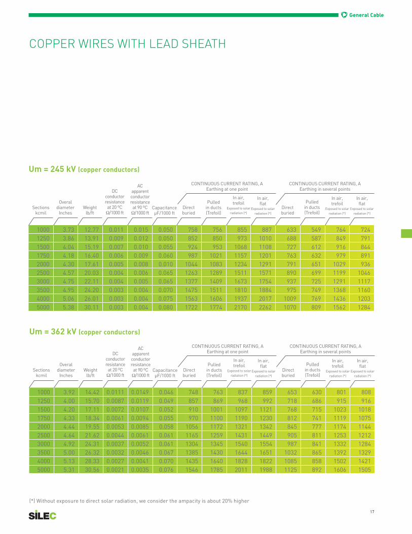
Um = 245 kV (copper conductors)
(*) Without exposure to direct solar radiation, we consider the ampacity is about 20% higher
COPPER WIRES WITH LEAD SHEATH
1000 3.73 12.77 0.011 0.015 0.050 758 756 855 887 633 549 764 7241250 3.86 13.91 0.009 0.012 0.050 852 850 973 1010 688 587 849 7911500 4.04 15.19 0.007 0.010 0.055 924 953 1068 1108 727 612 916 8441750 4.18 16.40 0.006 0.009 0.060 987 1021 1157 1201 763 632 979 8912000 4.30 17.61 0.005 0.008 0.010 1044 1083 1234 1291 791 651 1029 9362500 4.57 20.03 0.004 0.006 0.065 1263 1289 1511 1571 890 699 1199 10463000 4.75 22.11 0.004 0.005 0.065 1377 1409 1673 1754 937 725 1291 11173500 4.95 24.20 0.003 0.004 0.070 1475 1511 1810 1884 975 749 1368 11604000 5.06 26.01 0.003 0.004 0.075 1563 1606 1937 2017 1009 769 1436 12035000 5.38 30.11 0.003 0.004 0.080 1722 1774 2170 2262 1070 809 1562 1284
Sectionskcmil
Overaldiameter
InchesWeight
lb/ft
DCconductorresistance
at 20 ºCΩ/1000 ft
ACapparentconductorresistance
at 90 ºC Ω/1000 ft
CapacitanceµF/1000 ft
Directburied
Pulledin ducts(Trefoil)
In air,trefoil
Exposed to solarradiation (*)
In air,flat
Exposed to solarradiation (*)
Directburied
Pulledin ducts (Trefoil)
In air,trefoil
Exposed to solarradiation (*)
In air,flat
Exposed to solarradiation (*)
CONTINUOUS CURRENT RATING, AEarthing at one point
CONTINUOUS CURRENT RATING, A Earthing in several points
Um = 362 kV (copper conductors)
1000 3.92 14.42 0.0111 0.0149 0.046 748 763 837 859 653 630 801 8081250 4.00 15.70 0.0087 0.0119 0.049 857 869 968 992 718 686 915 9161500 4.20 17.11 0.0072 0.0107 0.052 910 1001 1097 1121 768 715 1023 10181750 4.33 18.34 0.0061 0.0094 0.055 970 1100 1190 1230 812 741 1119 10752000 4.44 19.55 0.0053 0.0085 0.058 1056 1172 1321 1342 845 777 1174 11442500 4.64 21.62 0.0044 0.0061 0.061 1165 1259 1431 1449 905 811 1253 12123000 4.92 24.31 0.0037 0.0052 0.061 1304 1345 1540 1554 987 841 1332 12843500 5.00 26.32 0.0032 0.0046 0.067 1385 1430 1644 1651 1032 865 1392 13294000 5.13 28.33 0.0027 0.0041 0.070 1435 1640 1828 1822 1085 858 1502 14215000 5.31 30.56 0.0021 0.0035 0.076 1546 1785 2011 1988 1125 892 1606 1505
Sectionskcmil
Overaldiameter
InchesWeight
lb/ft
DCconductorresistance
at 20 ºCΩ/1000 ft
ACapparentconductorresistance
at 90 ºC Ω/1000 ft
CapacitanceµF/1000 ft
Directburied
Pulledin ducts(Trefoil)
In air,trefoil
Exposed to solarradiation (*)
In air,flat
Exposed to solarradiation (*)
Directburied
Pulledin ducts (Trefoil)
In air,trefoil
Exposed to solarradiation (*)
In air,flat
Exposed to solarradiation (*)
CONTINUOUS CURRENT RATING, AEarthing at one point
CONTINUOUS CURRENT RATING, A Earthing in several points

18
General Cable
Um = 420 kV (copper conductors) - Maximum single-phase short-circuit = 63 kA - 1 s
(*) Without exposure to direct solar radiation, we consider the ampacity is about 20% higher
400 4.55 16.24 0.014 0.0616 0.040 665 678 713 735 641 605 700 715500 4.57 16.84 0.011 0.0488 0.040 758 775 831 856 723 671 811 825630 4.55 17.58 0.009 0.0389 0.045 857 882 958 986 807 737 927 940800 4.57 18.58 0.007 0.0317 0.050 958 993 1095 1126 890 800 1050 1060
1000 4.79 20.46 0.005 0.0234 0.055 1125 1164 1322 1355 995 884 1229 12191200 4.93 22.07 0.005 0.0204 0.055 1210 1255 1440 1474 1051 927 1323 13051600 5.16 25.36 0.003 0.0159 0.060 1370 1484 1664 1694 1148 954 1491 14532000 5.46 28.71 0.003 0.0133 0.065 1499 1638 1861 1886 1216 1003 1630 15722500 5.77 33.00 0.002 0.0113 0.070 1620 1785 2056 2073 1272 1048 1759 1679
Sectionsmm2
Overaldiameter
InchesWeight
lb/ft
DCconductorresistance
at 20 ºCΩ/1000 ft
ACapparentconductorresistance
at 90 ºC Ω/1000 ft
CapacitanceµF/1000 ft
Directburied
Pulledin ducts(Trefoil)
In air,trefoil
Exposed to solarradiation (*)
In air,flat
Exposed to solarradiation (*)
Directburied
Pulledin ducts (Trefoil)
In air,trefoil
Exposed to solarradiation (*)
In air,flat
Exposed to solarradiation (*)
CONTINUOUS CURRENT RATING, AEarthing at one point
CONTINUOUS CURRENT RATING, A Earthing in several points
Um = 550 kV (copper conductors) - Maximum single-phase short-circuit = 63 kA - 1 s
400 4.79 17.18 0.0143 0.0615 0.035 659 670 704 726 635 600 691 706500 4.75 17.58 0.0112 0.0488 0.040 751 766 821 846 716 667 801 816630 4.77 18.38 0.0086 0.0388 0.040 849 870 945 963 799 733 916 929800 4.89 19.79 0.0067 0.0316 0.045 949 977 1078 1108 881 797 1035 1045
1000 5.22 22.34 0.0054 0.0234 0.050 1112 1179 1292 1324 980 853 1204 11961200 5.38 24.15 0.0046 0.0203 0.050 1195 1271 1405 1437 1034 891 1295 12781600 5.63 27.50 0.0034 0.0158 0.055 1353 1452 1624 1643 1128 957 1461 14262000 5.91 30.86 0.0027 0.0132 0.055 1481 1601 1817 1842 1195 1007 1599 15452500 6.23 35.22 0.0022 0.0113 0.060 1601 1742 2010 2026 1251 1053 1728 1653
Sectionsmm2
Overaldiameter
InchesWeight
lb/ft
DCconductorresistance
at 20 ºCΩ/1000 ft
ACapparentconductorresistance
at 90 ºC Ω/1000 ft
CapacitanceµF/1000 ft
Directburied
Pulledin ducts(Trefoil)
In air,trefoil
Exposed to solarradiation (*)
In air,flat
Exposed to solarradiation (*)
Directburied
Pulledin ducts (Trefoil)
In air,trefoil
Exposed to solarradiation (*)
In air,flat
Exposed to solarradiation (*)
CONTINUOUS CURRENT RATING, AEarthing at one point
CONTINUOUS CURRENT RATING, A Earthing in several points
19
General Cable
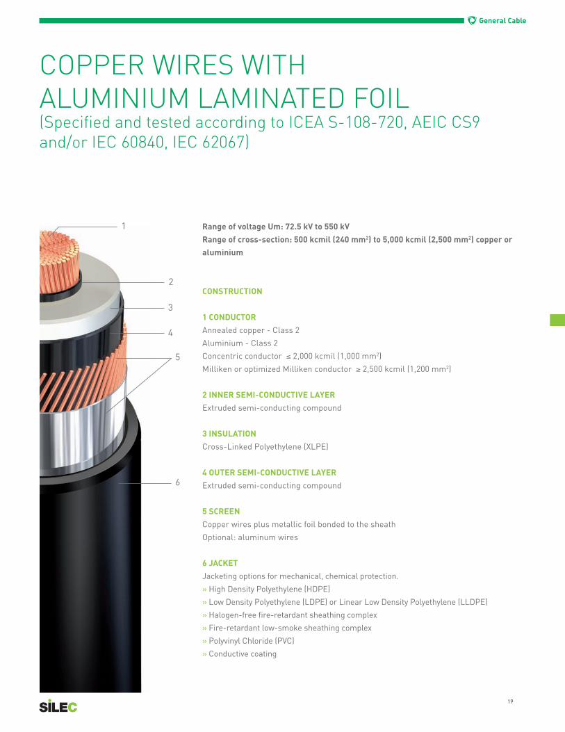
Range of voltage Um: 72.5 kV to 550 kV
Range of cross-section: 500 kcmil (240 mm2) to 5,000 kcmil (2,500 mm2) copper or
aluminium
CONSTRUCTION
1 CONDUCTOR
Annealed copper - Class 2
Aluminium - Class 2
Concentric conductor ≤ 2,000 kcmil (1,000 mm2)
Milliken or optimized Milliken conductor ≥ 2,500 kcmil (1,200 mm2)
2 INNER SEMI-CONDUCTIVE LAYER
Extruded semi-conducting compound
3 INSULATION
Cross-Linked Polyethylene (XLPE)
4 OUTER SEMI-CONDUCTIVE LAYER
Extruded semi-conducting compound
5 SCREEN
Copper wires plus metallic foil bonded to the sheath
Optional: aluminum wires
6 JACKET
Jacketing options for mechanical, chemical protection.
» High Density Polyethylene (HDPE)
» Low Density Polyethylene (LDPE) or Linear Low Density Polyethylene (LLDPE)
» Halogen-free fire-retardant sheathing complex
» Fire-retardant low-smoke sheathing complex
» Polyvinyl Chloride (PVC)
» Conductive coating
COPPER WIRES WITHALUMINIUM LAMINATED FOIL(Specified and tested according to ICEA S-108-720, AEIC CS9 and/or IEC 60840, IEC 62067)

20
General Cable
Um = 72.5 kV (copper conductors)
Um = 145 kV (copper conductors)
(*) Without exposure to direct solar radiation, we consider the ampacity is about 20% higher
COPPER WIRES WITH ALUMINIUM LAMINATED FOIL
500 2.31 3.84 0.022 0.028 0.075 538 541 590 612 493 417 553 532750 2.53 4.87 0.015 0.020 0.085 652 658 733 761 581 472 672 633
1000 2.73 5.87 0.011 0.015 0.095 765 773 880 915 659 518 785 7231250 2.90 6.95 0.009 0.012 0.105 857 870 1002 1042 718 552 874 7891500 3.04 7.85 0.007 0.010 0.110 927 945 1100 1145 762 579 945 8431750 3.18 8.90 0.007 0.010 0.120 988 1013 1191 1242 796 601 1007 8862000 3.28 9.85 0.005 0.008 0.125 1043 1073 1271 1325 821 617 1053 9182500 3.55 11.90 0.004 0.006 0.140 1267 1278 1570 1638 936 672 1236 10393000 3.73 13.71 0.004 0.005 0.145 1377 1394 1733 1810 985 706 1329 10993500 3.89 15.25 0.003 0.005 0.150 1468 1493 1875 1958 1018 730 1399 11444000 4.03 16.98 0.003 0.004 0.160 1552 1584 2000 2091 1039 747 1449 1168
Sectionskcmil
Overaldiameter
InchesWeight
lb/ft
DCconductorresistance
at 20 ºCΩ/1000 ft
ACapparentconductorresistance
at 90 ºC Ω/1000 ft
CapacitanceµF/1000 ft
Directburied
Pulledin ducts(Trefoil)
In air,trefoil
Exposed to solarradiation (*)
In air,flat
Exposed to solarradiation (*)
Directburied
Pulledin ducts (Trefoil)
In air,trefoil
Exposed to solarradiation (*)
In air,flat
Exposed to solarradiation (*)
CONTINUOUS CURRENT RATING, AEarthing at one point
CONTINUOUS CURRENT RATING, A Earthing in several points
500 2.87 5.10 0.022 0.028 0.055 534 553 584 605 482 430 543 525750 2.97 5.95 0.015 0.020 0.060 650 674 727 754 568 483 661 625
1000 3.27 7.93 0.011 0.015 0.065 759 791 865 898 644 529 769 7121250 3.24 7.93 0.009 0.012 0.070 851 891 983 1021 699 561 854 7771500 3.44 8.98 0.007 0.010 0.075 921 968 1078 1120 743 586 923 8291750 3.58 10.07 0.006 0.009 0.080 981 1038 1166 1213 778 607 985 8772000 3.68 10.97 0.005 0.008 0.080 1037 1101 1244 1295 812 624 1040 9162500 3.96 13.19 0.004 0.006 0.090 1256 1303 1529 1592 920 673 1214 10323000 4.14 15.02 0.004 0.005 0.095 1366 1423 1688 1759 976 703 1313 11013500 4.33 16.72 0.003 0.005 0.100 1457 1524 1824 1901 1016 726 1390 11504000 4.45 18.43 0.003 0.004 0.100 1538 1615 1940 2024 1040 743 1444 11815000 4.70 21.97 0.002 0.003 0.110 1683 1780 2165 2262 1097 779 1562 1255
Sectionskcmil
Overaldiameter
InchesWeight
lb/ft
DCconductorresistance
at 20 ºCΩ/1000 ft
ACapparentconductorresistance
at 90 ºC Ω/1000 ft
CapacitanceµF/1000 ft
Directburied
Pulledin ducts(Trefoil)
In air,trefoil
Exposed to solarradiation (*)
In air,flat
Exposed to solarradiation (*)
Directburied
Pulledin ducts (Trefoil)
In air,trefoil
Exposed to solarradiation (*)
In air,flat
Exposed to solarradiation (*)
CONTINUOUS CURRENT RATING, AEarthing at one point
CONTINUOUS CURRENT RATING, A Earthing in several points

21
General Cable
(*) Without exposure to direct solar radiation, we consider the ampacity is about 20% higher
COPPER WIRES WITH ALUMINIUM LAMINATED FOIL
Um = 245 kV (copper conductors)
1000 3.61 7.60 0.011 0.015 0.050 755 753 848 879 636 545 761 7171250 3.75 8.54 0.009 0.012 0.050 846 847 963 999 690 581 844 7811500 3.90 9.48 0.007 0.010 0.055 917 919 1057 1097 733 610 914 8361750 4.04 10.55 0.006 0.009 0.060 980 1018 1144 1188 766 625 973 8822000 4.16 11.50 0.005 0.008 0.060 1037 1079 1221 1268 799 643 1028 9232500 4.41 13.58 0.004 0.006 0.065 1255 1285 1497 1557 895 693 1194 10373000 4.59 15.39 0.004 0.005 0.070 1369 1405 1658 1724 941 719 1285 10993500 4.79 17.21 0.003 0.004 0.070 1466 1507 1793 1866 975 742 1356 11474000 4.91 18.89 0.003 0.004 0.075 1554 1602 1918 1998 1011 762 1426 11885000 5.20 22.31 0.003 0.004 0.080 1709 1769 2145 2236 1082 804 1560 1275
Sectionskcmil
Overaldiameter
InchesWeight
lb/ft
DCconductorresistance
at 20 ºCΩ/1000 ft
ACapparentconductorresistance
at 90 ºC Ω/1000 ft
CapacitanceµF/1000 ft
Directburied
Pulledin ducts(Trefoil)
In air,trefoil
Exposed to solarradiation (*)
In air,flat
Exposed to solarradiation (*)
Directburied
Pulledin ducts (Trefoil)
In air,trefoil
Exposed to solarradiation (*)
In air,flat
Exposed to solarradiation (*)
CONTINUOUS CURRENT RATING, AEarthing at one point
CONTINUOUS CURRENT RATING, A Earthing in several points
Um = 362 kV (copper conductors)
1000 3.69 8.00 0.0110 0.0150 0.046 744 741 839 871 622 541 750 7111250 3.85 9.00 0.0086 0.0122 0.049 834 832 953 989 674 576 831 7751500 4.01 10.00 0.0072 0.0106 0.049 903 902 1043 1083 714 604 897 8281750 4.14 11.00 0.0061 0.0094 0.055 965 999 1129 1173 746 622 956 8742000 4.16 11.84 0.0053 0.0086 0.058 1018 1060 1207 1256 768 636 1002 9062500 4.42 13.83 0.0044 0.0060 0.061 1230 1303 1478 1538 858 682 1160 10183000 4.72 15.72 0.0036 0.0052 0.067 1345 1423 1632 1699 905 712 1252 10833500 4.88 15.93 0.0031 0.0046 0.067 1438 1475 1768 1841 938 732 1312 11294000 5.18 27.51 0.0027 0.0041 0.070 1511 1662 1889 1915 1230 1001 1651 15895000 5.45 31.62 0.0021 0.0035 0.076 1633 1815 2090 2108 1287 1044 1782 1698
Sectionskcmil
Overaldiameter
InchesWeight
lb/ft
DCconductorresistance
at 20 ºCΩ/1000 ft
ACapparentconductorresistance
at 90 ºC Ω/1000 ft
CapacitanceµF/1000 ft
Directburied
Pulledin ducts(Trefoil)
In air,trefoil
Exposed to solarradiation (*)
In air,flat
Exposed to solarradiation (*)
Directburied
Pulledin ducts (Trefoil)
In air,trefoil
Exposed to solarradiation (*)
In air,flat
Exposed to solarradiation (*)
CONTINUOUS CURRENT RATING, AEarthing at one point
CONTINUOUS CURRENT RATING, A Earthing in several points

22
General Cable
Um = 420 kV (copper conductors) - Maximum single-phase short-circuit = 63 kA - 1 s
Um = 550 kV (copper conductors) - Maximum single-phase short-circuit = 63 kA - 1 s
(*) Without exposure to direct solar radiation, we consider the ampacity is about 20% higher
400 4.43 9.73 0.0143 0.0616 0.040 658 675 708 727 620 568 687 696500 4.45 10.27 0.0112 0.0488 0.040 747 772 823 844 693 622 790 798630 4.43 11.07 0.0086 0.0389 0.043 842 877 947 969 768 674 899 902800 4.47 12.01 0.0067 0.0317 0.049 938 986 1079 1102 839 721 1010 1006
1000 4.67 13.62 0.0054 0.0234 0.052 1096 1154 1298 1318 914 784 1160 11321200 4.81 15.03 0.0046 0.0204 0.055 1173 1241 1410 1427 955 815 1238 12001600 5.04 17.98 0.0034 0.0159 0.058 1317 1468 1620 1626 1026 826 1377 13182000 5.34 20.93 0.0027 0.0133 0.064 1430 1615 1803 1797 1075 865 1490 14142500 5.65 24.69 0.0022 0.0113 0.067 1532 1752 1981 1959 1113 900 1592 1498
Sectionsmm2
Overaldiameter
InchesWeight
lb/ft
DCconductorresistance
at 20 ºCΩ/1000 ft
ACapparentconductorresistance
at 90 ºC Ω/1000 ft
CapacitanceµF/1000 ft
Directburied
Pulledin ducts(Trefoil)
In air,trefoil
Exposed to solarradiation (*)
In air,flat
Exposed to solarradiation (*)
Directburied
Pulledin ducts (Trefoil)
In air,trefoil
Exposed to solarradiation (*)
In air,flat
Exposed to solarradiation (*)
CONTINUOUS CURRENT RATING, AEarthing at one point
CONTINUOUS CURRENT RATING, A Earthing in several points
400 4.67 10.33 0.0143 0.0615 0.040 652 667 699 718 614 566 679 689500 4.63 10.80 0.0112 0.0488 0.040 740 762 813 834 687 620 782 790630 4.65 11.61 0.0086 0.0388 0.040 834 865 934 957 760 672 888 892800 4.77 12.82 0.0067 0.0316 0.050 929 970 1063 1085 830 722 997 995
1000 5.10 14.90 0.0054 0.0234 0.050 1082 1170 1270 1289 900 759 1140 11161200 5.28 16.37 0.0046 0.0203 0.050 1158 1259 1378 1394 941 788 1185 12181600 5.52 19.39 0.0034 0.0158 0.055 1299 1434 1584 1590 1011 836 1357 13052000 5.79 22.41 0.0027 0.0132 0.055 1410 1573 1763 1757 1057 874 1468 13992500 6.11 26.23 0.0022 0.0113 0.060 1510 1703 1939 1918 1094 909 1571 1485
Sectionsmm2
Overaldiameter
InchesWeight
lb/ft
DCconductorresistance
at 20 ºCΩ/1000 ft
ACapparentconductorresistance
at 90 ºC Ω/1000 ft
CapacitanceµF/1000 ft
Directburied
Pulledin ducts(Trefoil)
In air,trefoil
Exposed to solarradiation (*)
In air,flat
Exposed to solarradiation (*)
Directburied
Pulledin ducts (Trefoil)
In air,trefoil
Exposed to solarradiation (*)
In air,flat
Exposed to solarradiation (*)
CONTINUOUS CURRENT RATING, AEarthing at one point
CONTINUOUS CURRENT RATING, A Earthing in several points

24
General Cable
CURRENT RATINGS - CORRECTION FACTORS
The tables in this section cover the installation conditions most commonly encountered. The following correction factors have been provided in order to calculate various laying conditions based on these five parameters:
» Temperature of the ground» Temperature of the air» Laying depth» Thermal resistivity of the ground» Proximity of circuits
The relating factors are given in the following tables:
GROUND TEMPERATUREGround Temperature (ºC) 10 15 20 25 30 35 40 45Correction Factor 1.07 1.04 1 0.96 0.93 0.88 0.84 0.8
AIR TEMPERATUREAir Temperature (ºC) 10 20 30 40 50 60Correction Factor 1.18 1.1 1 0.9 0.79 0.67
LAYING DEPTHLaying Depth (m) 1.0 1.2 1.5 2.0 2.5 3.0 4.0 5.0Correction Factor 1.05 1.03 1 0.97 0.95 0.92 0.89 0.87
THERMAL RESISTIVITY OF THE GROUNDThermal Resistivity (Km/W) 0.8 1.0 1.2 1.5 2.0 2.5Correction Factor 1.09 1 0.93 0.85 0.74 0.67
PROXIMITY OF CIRCUIT
Axis-to-axis spacing between 2Cable Systems (*) (mm)
Number of Cable Systems (*)1 2 3 4 5 6
200 1 0.78 0.67 0.61 0.60 0.57400 1 0.83 0.73 0.68 0.67 0.65600 1 0.86 0.78 0.75 0.72 0.70800 1 0.89 0.80 0.78 0.75 0.74
(*) A cable system is a set
of 3 phase conductors

25
General Cable
CABLE HANDLING DURING INSTALLATION
Minimum Bending Radius
» Minimum bending radius when pulling on rolls: 30 D» Minimum bending radius when pulling in pipes: 35 D» Minimum bending radius after installation: 20 D
D = the overall diameter of the cable
Maximum Pulling Force
A traction force is applied at one end of the cable when pulling a cable. Most of the stress is supported by the conductor, so a pulling head has to be secured to the conductor.
Use of a pulling sleeve is restricted where the pulling force is limited to a maximum of 1,125 lbs (500 daN).
Maximum tensile load on the conductor:» 5 daN/mm2 for aluminium conductors» 6 daN/mm2 for copper conductors
The rated tensile strength of standard pulling heads is 4000 daN.
Maximum Sidewall Pressure
Type of design In ducts (lbs/ft) On rollers (lbs)
Wires + aluminium foil 700 225
Aluminium foil alone 2,000 225
Wires + lead sheath 700 225
Lead sheath alone 2,000 225
Any type of metal screen with fiber optics 700 225
Cables installed in tunnel
The above data should be used when performing a preliminary assessment. General Cable advises its customers to contact us for the engineering of each cable link, as each project is a specific case of study.
26
General Cable
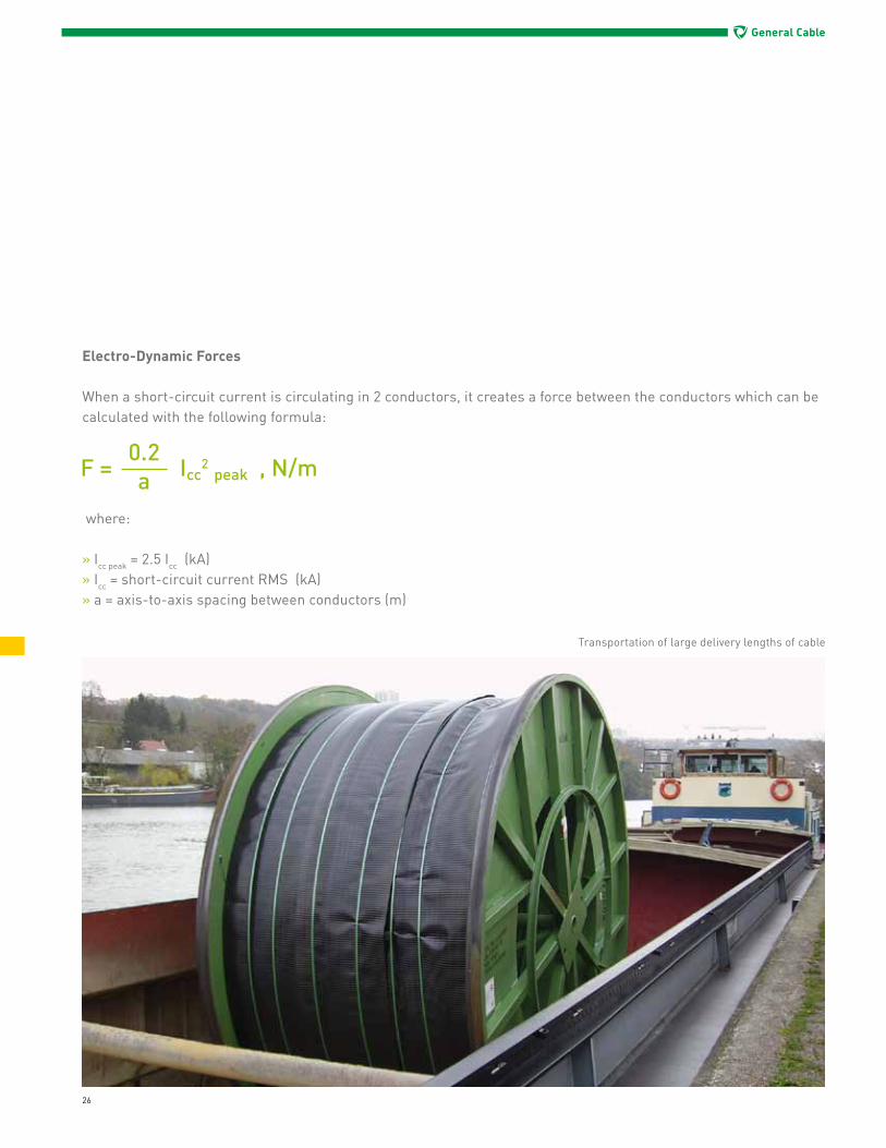
Electro-Dynamic Forces
When a short-circuit current is circulating in 2 conductors, it creates a force between the conductors which can be calculated with the following formula:
where:
» Icc peak = 2.5 Icc (kA)» Icc = short-circuit current RMS (kA)» a = axis-to-axis spacing between conductors (m)
Transportation of large delivery lengths of cable

27
General Cable
APPARENT TRANSMISSION CHARACTERISTICS
Capacitance:
where:
» ε = relative permittivity of the insulation» r1 = radius at the surface of the conductor screen (mm)» r2 = radius at the surface of the insulation (mm)
Dielectric Losses:
where:
» U0 = is the applied voltage between the conductor and the metal screen (kV)» C = capacitance of the cable (µF/km)» w = 2 π f where f is the frequency (Hz)» tgd = is the loss angle
Inductance
where:
» am = a in trefoil formation where a is the axis-to-axis spacing between conductors (mm) am = 1.26 a in flat formation where a is the axis to axis spacing between conductors (mm)» d = diameter of the conductor (mm)

28
General Cable
Electric Stress
Electric stress over the surface of the conductor screen:
Electric stress over the surface of the insulation:
where:
» U0 = is the applied voltage between the conductor and the metal screen (kV)» r1 = radius at the surface of the conductor screen (mm)» r2 = radius at the surface of the insulation (mm)
Stand-by links (each fitted with one GIS termination and one outdoor termination)

30
General Cable
INTRODUCTION
General Cable offers some of the most advanced high-voltage technology in the industry, with an uncompromised commitment to continuous improvement that results in superior, cost-effective cable systems with a maximum service.
Adhering to strict manufacturing standards, Silec accessories provide maximum flexibility with tight tolerances, backed by the expertise and technology to deliver quality, customized cable solutions.
In understanding the need for maximum reliability of this vital part of the complete HV/EHV cable system, General Cable considers the following parameters when designing and recommending a cable accessory:
» Thermo-mechanical and dynamic stress: When in service, joints and terminations can be highly stressed due to heat-cycling in service. That is why our engineering team is always carefully evaluating what types of materials and installation practices are the most suitable to ensure long-term reliability.
» Water-tightness: It is well-known that water ingress can cause failures. The durability and ingress protection of our cable accessories are assured with sealed devices that are compliant to IEC 62067 standards. These devices are thoroughly tested in recognized international test laboratories. General Cable ensures the availability and training of highly qualified jointers to secure the reliability of the installed accessories.
» The complete bonding system of joints and terminations is tested and approved according to the recommendations of transmission network operators.
Shielded room for testing
of EHV cables (France)

31
General Cable
SYNTHETIC OUTDOORTERMINATION
These slip-on terminations are dry-types and designed for modular assembly. They are based on pre-moulded stress - the number of which is determined by the required creepage distance. These products are designed for operation under severe outdoor conditions.
» Range of maximum rated voltage (Um): 72.5 to 123 kV For 145 kV and above, please contact us.» Range of cable cross-section: 300 to 3,200 kcmil (150 to 1,600 mm2)» Pollution level: 16 mm/kV to 31 mm/kV
Various connection options for the cable conductor and the metal screen are available according to customer requests. Combined with a relevant supporting structure such as a pillar, it makes a self-supporting dry-type termination. Please contact us for more information.
Maximum Rated Voltage Um (kV) 72.5 123
Basic Impulse Level (kV) 325 550
Approximate Height (mm) 1,500 2,000

32
General Cable
These terminations are slip-on and designed for outdoor environments. They are based on pre-moulded stress-control blocks (silicone or EPDM rubber) and composite or porcelain insulators, with the overall length and the shed profile determined by the required creepage distance. These terminations are designed for operation under severe outdoor conditions, including polluted areas.
» Range of maximum rated voltage (Um): 72.5 to 550 kV
» Range of cable cross-section: 300 to 5,000 kcmil (150 to 2,500 mm2)
» Pollution level: 16 mm/kV to 31 mm/kV, or more on demand
Various connection options for the cable conductor and the metal screen are available according to customer requests.
Post-insulators are used to electrically insulate the cable screen from the metallic frame.
Maximum Rated Voltage Um (kV) 72.5 123 145 170 245 362 420 550
Basic Impulse Level (kV) 325 550 650 750 1,050 1,175 1,425 1,550
Approximate Height (mm) 1,900 2,150 2,150 6,000 6,000 4,750 4,750 6,000
OUTDOOR TERMINATION
33
General Cable
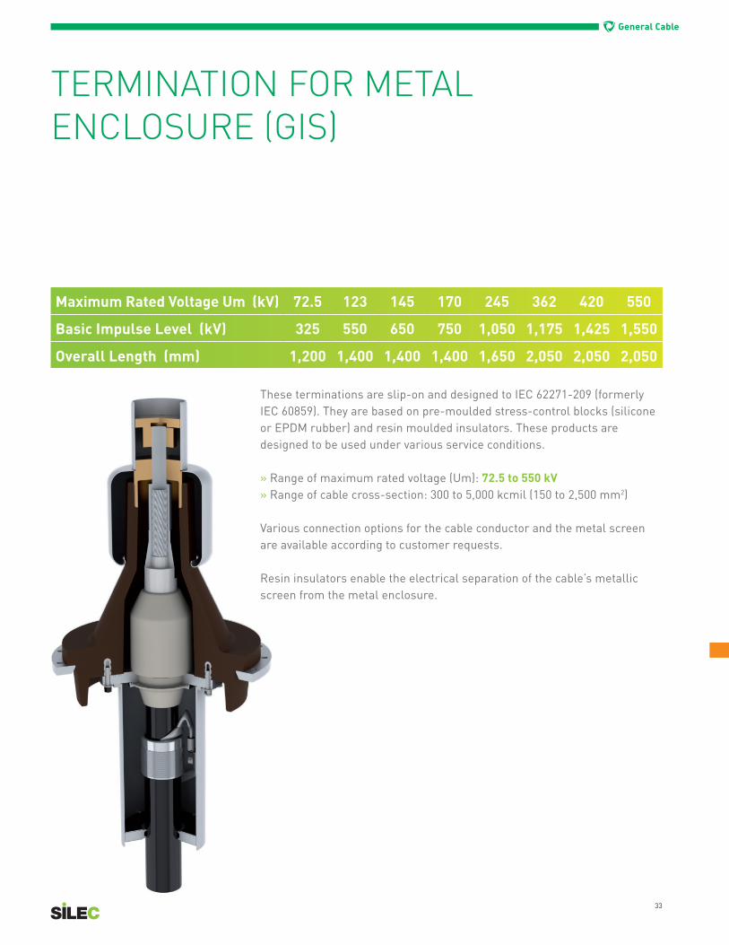
TERMINATION FOR METAL ENCLOSURE (GIS)
These terminations are slip-on and designed to IEC 62271-209 (formerly IEC 60859). They are based on pre-moulded stress-control blocks (silicone or EPDM rubber) and resin moulded insulators. These products are designed to be used under various service conditions.
» Range of maximum rated voltage (Um): 72.5 to 550 kV» Range of cable cross-section: 300 to 5,000 kcmil (150 to 2,500 mm2)
Various connection options for the cable conductor and the metal screen are available according to customer requests.
Resin insulators enable the electrical separation of the cable’s metallic screen from the metal enclosure.
Maximum Rated Voltage Um (kV) 72.5 123 145 170 245 362 420 550
Basic Impulse Level (kV) 325 550 650 750 1,050 1,175 1,425 1,550
Overall Length (mm) 1,200 1,400 1,400 1,400 1,650 2,050 2,050 2,050

34
General Cable
OIL-IMMERSED TERMINATIONFOR METAL ENCLOSURE (TRANSFORMER)
Maximum Rated Voltage Um (kV) 72.5 123 145 170 245
Basic Impulse Level (kV) 325 550 650 750 1,050
Maximum Height (mm) 1,300 1,450 1,450 1,450 1,750
These terminations are a slip-on type. They are based on pre-moulded stress-control blocks (silicone or EPDM rubber) and resin moulded insulators. These products are designed for used under various service conditions.
» Range of maximum rated voltage (Um): 72.5 to 245 kV For 362 kV and above, please contact us» Range of cable cross-section: 300 to 5,000 kcmil (150 to 2,500 mm2)
Various connection options for the cable conductor and the metallic screen are available according to customer requests.
Resin insulators enable the insulating of the cable’s metallic screen from the metal enclosure.

General Cable
35
TAPED JOINTS
Maximum Rated Voltage Um (kV) 72.5 123 145
Basic Impulse Level (kV) 325 550 650
Approximate Length (mm) (*) 2,000 2,000 2,000
General Cable’s taped joints offer a wrapping installation technique that provides excellent flexibility and enables the connection of cables in a variety of configurations, such as reduced spaces, cables of different sizes, cables of different designs, and cables of different insulation types, to mention a few.
» Range of maximum rated voltage (Um): 72.5 to 145 kV» Range of cable cross-section: 300 to 5,000 kcmil (150 to 2,500 mm2)
Various connection options for the cable conductor and the metal screen are available per customer requests.
(*) This length varies from one configuration to another and should bechecked on a case-by-case basis.
36
General Cable
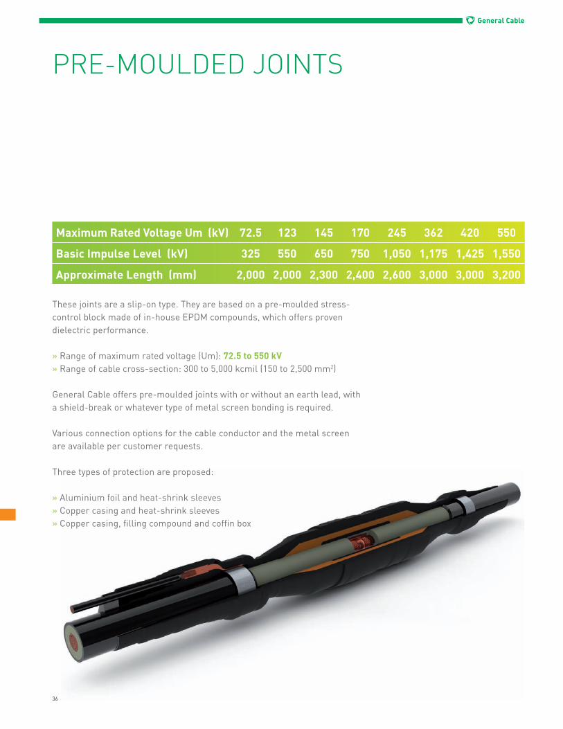
These joints are a slip-on type. They are based on a pre-moulded stress-control block made of in-house EPDM compounds, which offers proven dielectric performance.
» Range of maximum rated voltage (Um): 72.5 to 550 kV» Range of cable cross-section: 300 to 5,000 kcmil (150 to 2,500 mm2)
General Cable offers pre-moulded joints with or without an earth lead, with a shield-break or whatever type of metal screen bonding is required.
Various connection options for the cable conductor and the metal screen are available per customer requests.
Three types of protection are proposed:
» Aluminium foil and heat-shrink sleeves» Copper casing and heat-shrink sleeves» Copper casing, filling compound and coffin box
PRE-MOULDED JOINTS
Maximum Rated Voltage Um (kV) 72.5 123 145 170 245 362 420 550
Basic Impulse Level (kV) 325 550 650 750 1,050 1,175 1,425 1,550
Approximate Length (mm) 2,000 2,000 2,300 2,400 2,600 3,000 3,000 3,200

37
General Cable
As part of a complete cable system, link boxes are vital for the reliability of the cable system. In relation to the bonding concept, General Cable can design and supply the necessary link boxes that make it possible to:
» Access the metallic sheath in order to test the outer protection of the system and limit transient over-voltage by the insertion of surge voltage limiters inside the boxes
» Transpose metal screens at the joints to enable limitation of circulating currents, and protection against over-voltage by the insertion of Surge Voltage Limiters
Different types of link boxes are available for compatibility with the earthing concept at each point of the cable link:
» Single-core earthing» Three-core earthing» Cross-bonding: 2 sizes are available,
depending on the required dielectric strength
LINK BOXES
Type of Link Box Approximate Sizemm x mm Bonding
Single-Core Earthing 600 x 350 Single-Core Cable
Three-Core Earthing 600 x 600 Single-Core Cable
Cross-bonding 600 x 6001,000 x 1,000 Coaxial cable
As required, specific link boxes can be designed to address specific project requirements.

38
General Cable
CODIFICATIONOF CABLE ACCESSORIESTo make it easy to identify what type of cable accessory is needed, you will find below the identification codes to be used for our cable accessories.
CABLE JOINTS
Type of accessoryPJ = pre-moulded jointWJ = wrapped joint
Maximum rated voltage72.5 for Um = 72.5 kV100 for Um = 100 kV123 for Um = 123 kV145 for Um = 145 kV170 for Um = 170 kV245 for Um = 245 kV362 for Um = 362 kV420 for Um = 420 kV550 for Um = 550 kV
Bonding connectionSM = straight joint without earthingAM = straight joint with earthingXC = cross-bonding with coaxial leadX2L = cross-bonding with 2 single-core leads
Type of metallic screen to connectL = lead sheathWL = wires + lead sheathW = wiresAF = aluminium foilWAF = wires + aluminium foilAS = aluminium sheath
Radial moisture barrier of the jointAT = aluminium tapeCC = copper casing
Overprotection of the jointH = heat-shrink sleevesG = coffin box filled with compoundIR = injected resin protection
OptionOFI = embedded optical fibres internally connected OFE = embedded optical fibres externally connected
OUTDOOR SEALING END
Type of accessoryOSE = outdoor sealing end
Type of insulatorC = compositeP = porcelainS = synthetic protection
Maximum rated voltage72.5 for Um = 72.5 kV100 for Um = 100 kV123 for Um = 123 kV145 for Um = 145 kV170 for Um = 170 kV245 for Um = 245 kV362 for Um = 362 kV420 for Um = 420 kV550 for Um = 550 kV
Type of metallic screen to connectL = lead sheathWL = wires + lead sheathW = wiresAF = aluminium foilWAF = wires + aluminium foilAS = aluminium sheath
Pollution level P1 = 16 mm/kVP2 = 20 mm/kVP3 = 25 mm/kVP4 = 31 mm/kVP5 = more than 31 mm/kV
Insulation fluidO = oilG = gasD = dry
OptionOFE = embedded optical fibres externally connected
METAL-ENCLOSED CONNECTION
Type of accessoryMEC = metal-enclosed termination
Type of insulatorR = resinI = directly immersed
Maximum rated voltage72.5 for Um = 72.5 kV100 for Um = 100 kV123 for Um = 123 kV145 for Um = 145 kV170 for Um = 170 kV245 for Um = 245 kV362 for Um = 362 kV420 for Um = 420 kV550 for Um = 550 kV
Type of metallic screen to connectL = lead sheathWL = wires + lead sheathW = wiresAF = aluminium foilWAF = wires + aluminium foilAS = aluminium sheath
Type of interfaceFF859 = fluid-filled dimension according to IEC 60859DT859 = dry-type dimension according to IEC 60859FF271 = fluid-filled dimension according to IEC 62271-209DT271 = dry-type dimension according to IEC 62271-209TWS = transformerT299 = transformer dimension according to EN 50299
Insulation fluidO = oilG = gasD = dry
OptionOFE = embedded optical fibres externally connected
Catalogue Number ConstructionExample:
PJ-123-SM-WAF-CC-H This is a pre-moulded straight joint without earthing, suitable for a 115 kV (Um = 123 kV) cable system. The cable has a wire screen with an aluminium foil laminate. The splice is protected within a copper casing, and there is a heat-shrink outer protection over the casing to insulate it from ground. This cable system does not have an integrated fibre.

39
General Cable
MONITORING AND DIAGNOSIS
Monitoring of Underground Cable LinkGeneral Cable can embed optical fibres in the metal screen of the cable and supply monitoring sensors and systems that will allow the customer to optimize the operation of the underground transmission system. The system is designed to: » Measure the temperature so as to detect hot spots along the cable route » Calculate available transmission capacity based on the temperature of the cable and other parameters utilizing a software-based system
On-Site PD DetectionPossible quality assessment of the cable system throughout its entire life can be offered utilizing capacitive sensors embedded in the joints of the cable system or inductive sensors set up in the link boxes.
Splicing of embedded optical fibres

42
General Cable
TURNKEY SERVICES
Benefiting from years of experience, General Cable’s HV/EHV specialists provide superior turnkey services fornew cable projects or the upgrading of existing cable circuits. From system and installation enginering, project management and testing to diagnosis, post-project services and training, General Cable is your best partnerto install, test and service your entire cable system.
System Engineering & ManagementOur HV/EHV specialists work to develop cable and circuit design according to your specification. Through our experienced and skilled project managers and technicians, General Cable is able to take your project from system design to installation and termination while providing the management and consulting needed to ensure that your project runs smoothly and efficiently.
» Complete and custom cable system design» Project, safety and environmental management and consulting» On-site installation, termination and coordination
On-site testing (USA)

43
General Cable
On-Site TestingGeneral Cable performs all types of site testing needed to ensure that your system will perform and operate effectively and efficiently while meeting all required standards.
» Cable route visual inspection» Serving test on oversheaths» Investigation of leaks (SF6, oil) and system faults and failures» HV-resonant tests and partial discharge measurement» Comprehensive test reports
Diagnosis & Spare PartsExternal events can affect your network and reduce its life expectancy. Ongoing diagnosis and assessment of your network today can help you avoid problems tomorrow. General Cable’s highly advanced technical consultants and laboratories in France are well-equipped to investigate materials and components. Our experts put forth their technical knowledge to conduct comprehensive site testing, implement immediate preventive measures, and continually assess and renew your spare parts inventory to maintain ongoing operations.
» Problem analysis and solutions» Prompt maintenance and replacement of circuit parts» Preventive technical assessments» Material and component testing» Ongoing spare parts delivery
TrainingGeneral Cable’s Silec training center provides your maintenance crews with the information they need to ensure a high level of knowledge on all Silec products, joints and terminations.
» Customized training sessions » On-site training delivery» Ongoing refreshing of knowledge
General Cable testing& commissioning truck (Spain)

44
General Cable
CUSTOMER SERVICE
With more than 14,000 km of cables, 30,000 terminations and 18,000 splices installed and commissioned since 1962, General Cable is your best customer service partner. Since 2010, the Silec Services Department has met customers’ expectations by speeding up implementation and improving the efficiency of our service. Our splicers, who are thoroughly trained in our dedicated on-site training center, have enriched their knowledge on several worldwide projects with a specification in High Voltage and Extra High Voltage (63 kV to 500 kV).
Our Expedited ProcessFrom understanding our customer needs and expectations to providing the support and installation they need, we serve you well. With our highly qualified splicers, our customers are ensured an operational network as quickly as possible. When you need us, our experts will service your needs in less than 48 hours. And with a skilled workforce spread across all five continents, General Cable is able to provide the fastest response, whatever the location. For customer service, please send your requests to [email protected]
Skills and ResourcesWith the expertise, tools and workforce to deliver the best assessment, General Cable gains complete knowledge of your network to optimize customer service and value.
» All services compliant with quality, safety, health and environmental regulations (ISO 9001 and 14001)» Fully-equipped portable testing units across three continents» Specific tools to detect and locate SF6 and oil leakages, cable damages and optical fibre faults
NEEDSEXPECTATIONS
CUSTOMER
SUPPORT
INSTALLATION
ANALYSISIMPLEMENTATION
DEPLOYMENTEXECUTION

45
General Cable
General Cable Projects team
SERVICE DEPARTMENT(Project Management)CUSTOMER CUSTOMER
EXPERTSENGINEERING
SPARE PARTSIN WAREHOUSE
WORKFORCE:- SPLICERS AND SUPERVISORS
SUPPORTING UNITS: - BUSINESS - OPERATIONS - QHSE
48
General Cable
General Cable has been providing customers with ready-to-use stand-by links during maintenance or repair operations in numerous applications since the 1970s, offering the continuity of service to maintain end-consumer satisfaction and avoid business losses. Some of our stand-by links have been in service for more than 60,000 hours, having undergone many connections and disconnections.
Our Silec Brand stand-by links are proposed for use during the following situations as they provide service for 60 kV to 220 kV transmission grids; constructed with outdoor sealing ends and/or metal enclosed terminations; easy to handle and set up; reusable after each disconnection; and come with tailored maintenance programs.
» Refurbishment and reconstruction of tower and overhead lines» Restoration and expansion of high voltage substations» Plant substitutions in high voltage substations
For over 220 kV, please contact us.
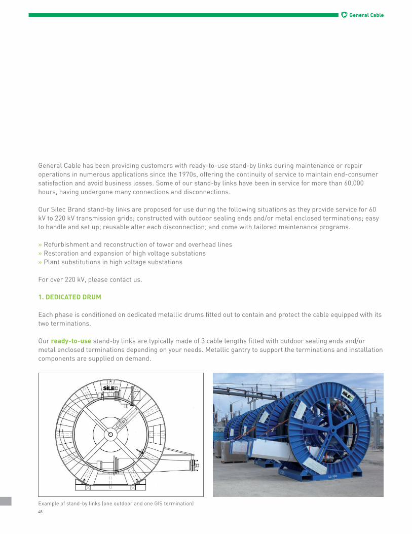
1. DEDICATED DRUM
Each phase is conditioned on dedicated metallic drums fitted out to contain and protect the cable equipped with its two terminations.
Our ready-to-use stand-by links are typically made of 3 cable lengths fitted with outdoor sealing ends and/or metal enclosed terminations depending on your needs. Metallic gantry to support the terminations and installation components are supplied on demand.
Example of stand-by links (one outdoor and one GIS termination)
49
General Cable
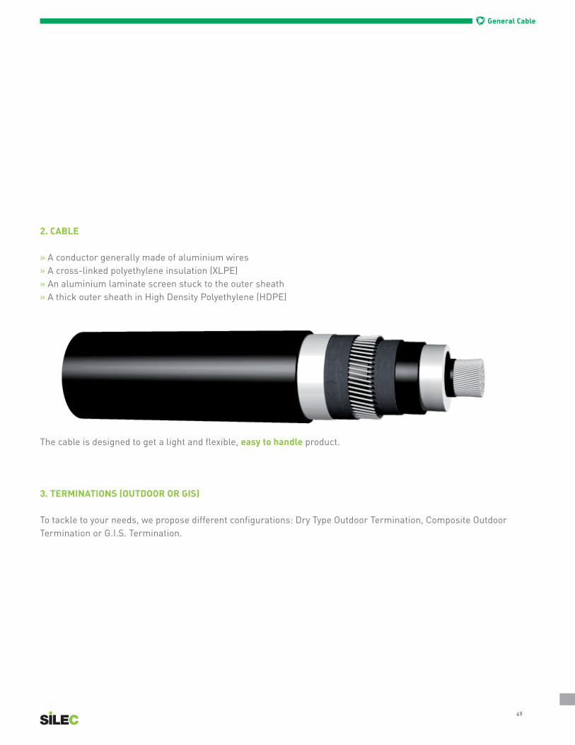
2. CABLE
» A conductor generally made of aluminium wires» A cross-linked polyethylene insulation (XLPE)» An aluminium laminate screen stuck to the outer sheath » A thick outer sheath in High Density Polyethylene (HDPE)
The cable is designed to get a light and flexible, easy to handle product.
3. TERMINATIONS (OUTDOOR OR GIS)
To tackle to your needs, we propose different configurations: Dry Type Outdoor Termination, Composite Outdoor Termination or G.I.S. Termination.

50
General Cable
IN-HOUSE ASSEMBLING
The entire stand-by link system is designed, manufactured and equipped in-house to provide ready-to-use equipment.After standard operations of manufacturing and testing, the cable is unreeled on the dedicated stand-by link drum and prepared to receive each termination.The termination is then installed and fixed to the drum for further transportation.Each stand-by link is finally tested in our labs before shipping.
ON-SITE INSTALLATION
For reconstruction of tower and overhead lines, restoration and expansion in high voltage substations, or plant substitutions in high voltage substations, stand-by links are the solution for maintaining continuity of service on power networks.General Cable can provide you with all accessories needed for the installation of a stand-by link, as well as providing the installation.Though stand-by links are easy to use, we recommend that the first installation is done under the supervision of General Cable’s trained staff as there are many advantages to the system that can be conveyed at the time of installation.
Stand-by links in service
51
General Cable
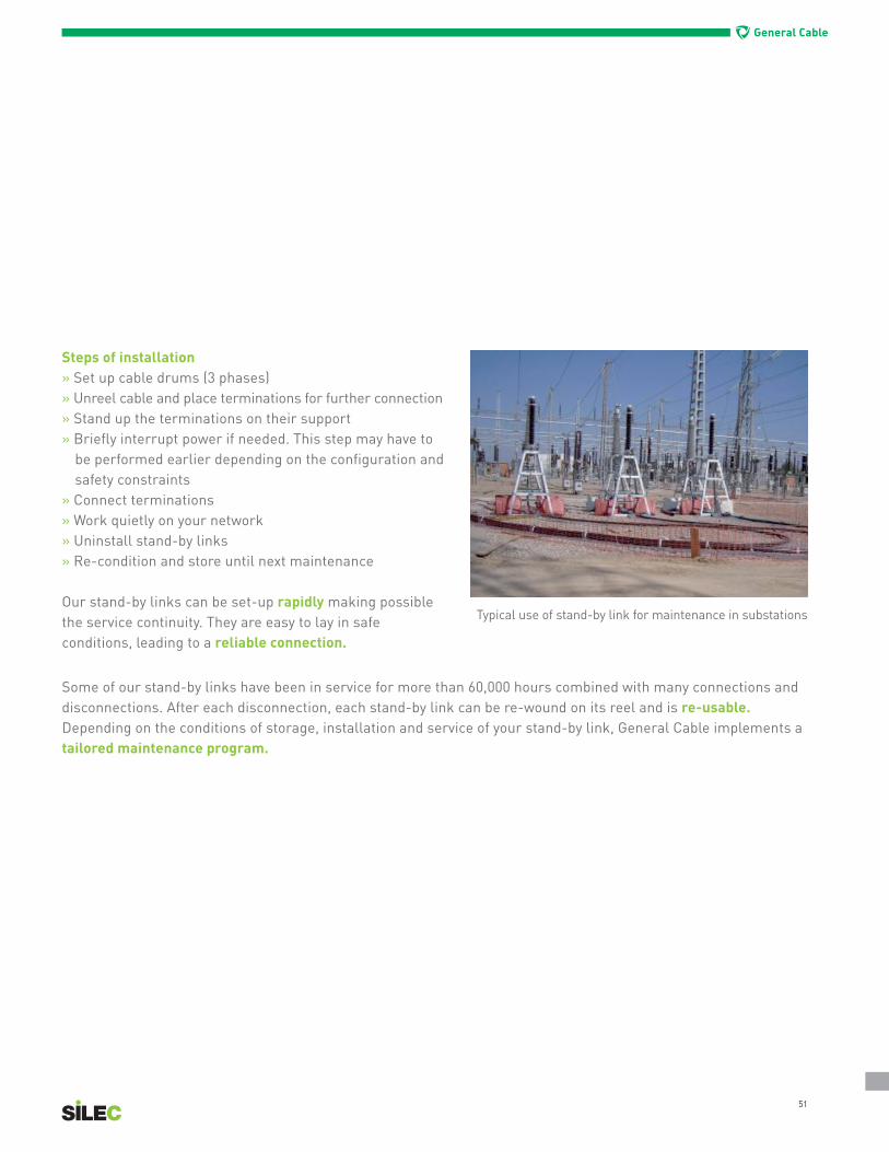
Steps of installation» Set up cable drums (3 phases)» Unreel cable and place terminations for further connection » Stand up the terminations on their support » Briefly interrupt power if needed. This step may have to
be performed earlier depending on the configuration and safety constraints
» Connect terminations » Work quietly on your network» Uninstall stand-by links» Re-condition and store until next maintenance
Our stand-by links can be set-up rapidly making possible the service continuity. They are easy to lay in safe conditions, leading to a reliable connection.
Some of our stand-by links have been in service for more than 60,000 hours combined with many connections and disconnections. After each disconnection, each stand-by link can be re-wound on its reel and is re-usable.Depending on the conditions of storage, installation and service of your stand-by link, General Cable implements a tailored maintenance program.
Typical use of stand-by link for maintenance in substations

GLOBAL REACH General Cable serves customers through a global network of 47 manufacturing facilities in 25
countries and sales representatives and distribution centers worldwide. The Company is solely dedicated to the production of high quality energy, industrial, specialty and communications wire
and cable products. In addition to its breadth of product line and strong brand recognition, the Company offers competitive strengths in such areas as technology, manufacturing, distribution and
logistics, and sales and customer service. This combination enables General Cable to better serve its customers as they expand into new geographic markets.
4 Tesseneer Drive Highland Heights, Kentucky 41076-9753 Phone: 1.800.237.2726 [email protected]
590 Barmac Drive North York Ontario, Canada M9L 2X8 Phone: +1.800.561.0649 [email protected]
GENERAL CABLE and SILEC are registered trademarks of General Cable Technologies Corporation.
©2012. General Cable Technologies Corporation. Highland Heights, KY 41076
All rights reserved.
Printed in USA.
Form No. UTY-0049-0112


![Presentation Overview of EHV cables - Inno Consultinginnoconsulting.com.ar/...Presentation_Overview_of_EHV_cables[1].pdf · Extra High Voltage (EHV) underground cables form part of](https://img.pdfslide.net/doc/110x75/5e88c6398cf2db10e37d0593/presentation-overview-of-ehv-cables-inno-cons-1pdf-extra-high-voltage-ehv.jpg)