Embed Size (px)
Citation preview

T3T SeriesT3T Series
HIGH FORCE GAS SPRINGS
APPROVED
97/23/EC
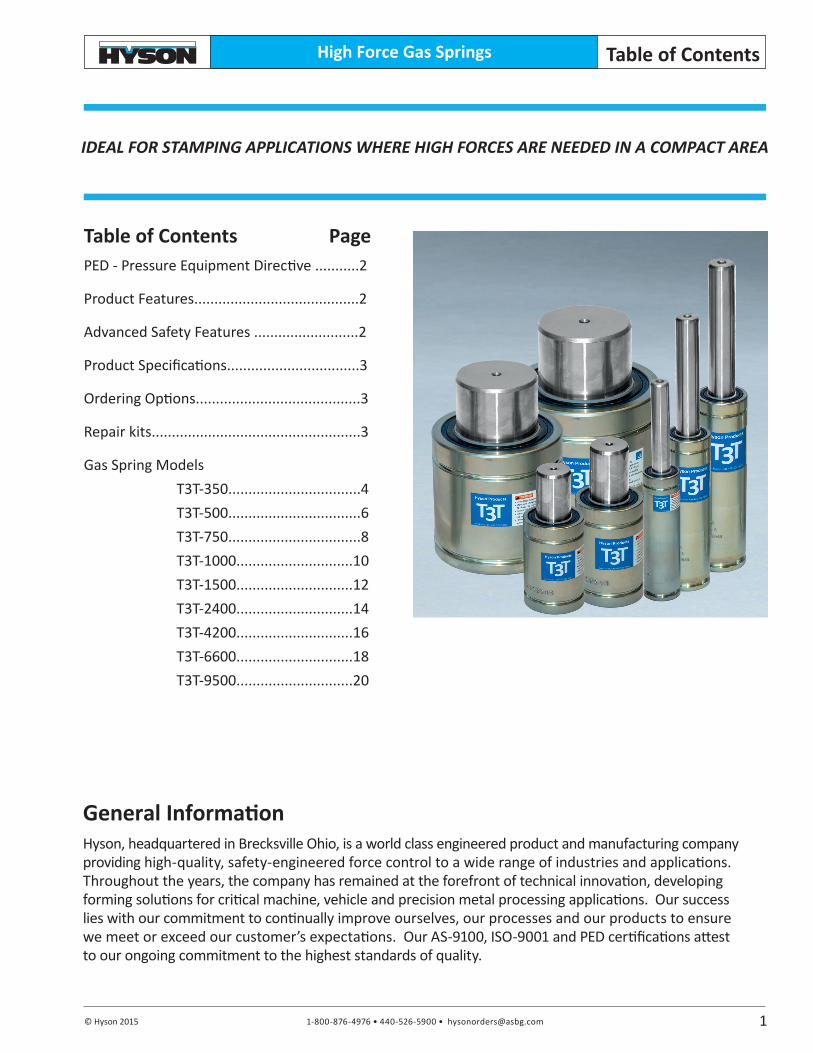
IDEAL FOR STAMPING APPLICATIONS WHERE HIGH FORCES ARE NEEDED IN A COMPACT AREA

1-800-876-4976 • 440-526-5900 • [email protected] © Hyson 2015
High Force Gas Springs
10367 Brecksville Road | Brecksville, Ohio 44131 www.HysonProducts.com |[email protected]
GENUINELY HYSON
Since 1939 Hyson has been dedicated to providing safer and more reliable products with worldwide support and service. We are continually at the forefront of innovative product design and engineer forward-thinking features into our self-contained springs that enable our customers to provide safer working environments. Our nitrogen gas springs, which comply with all major industry standards are designed to reduce risk of tool damage and injuries due to parts separating under high pressure and include at least one vital safety features:
Overstroke Protection:
In the event of an overstroke, the Hyson cylinder is designed to fail-safe and release pressure in a pre-defined manner with deformation or knockout plug.
Overpressure Protection:
Designed to vent excessive gas in the event that the spring becomes overpressured with drawing fluid, deformation of the safety lip guide or separation of disc will occur.
Overload Protection:
Reduce injuries and press damage with Overload Protection - In case of jammed tool, part or rod side-load, the piston rod is designed for controlled gas venting between the seal and piston rod with a specially designed guide and fundamental safety stop.
Additionally, the majority of Hyson springs are PED (Pressure Equipment Directive) approved to withstand a minimum of 2 million full cycles according to PED 97/23/EC. Many of our competitors are in compliance of PED, but compliance is unequal to the 2 million cycle test and approval that HYSON gas springs have undergone. This is one more assurance that with Hyson Nitrogen Gas Springs you receive an added value of
reliability and operational excellence.
1-800-876-4976 • 440-526-5900 • [email protected] © Hyson 2015
High Force Gas Springs
Table of Contents PagePED - Pressure Equipment Directive ...........2
Product Features.........................................2
Advanced Safety Features ..........................2
Product Specifications.................................3
Ordering Options.........................................3
Repair kits....................................................3
Gas Spring Models T3T-350.................................4 T3T-500.................................6 T3T-750.................................8 T3T-1000.............................10 T3T-1500.............................12 T3T-2400.............................14 T3T-4200.............................16 T3T-6600.............................18 T3T-9500.............................20
Table of Contents
General InformationHyson, headquartered in Brecksville Ohio, is a world class engineered product and manufacturing company providing high-quality, safety-engineered force control to a wide range of industries and applications. Throughout the years, the company has remained at the forefront of technical innovation, developing forming solutions for critical machine, vehicle and precision metal processing applications. Our success lies with our commitment to continually improve ourselves, our processes and our products to ensure we meet or exceed our customer’s expectations. Our AS-9100, ISO-9001 and PED certifications attest to our ongoing commitment to the highest standards of quality.
IDEAL FOR STAMPING APPLICATIONS WHERE HIGH FORCES ARE NEEDED IN A COMPACT AREA
1

1-800-876-4976 • 440-526-5900 • [email protected] © Hyson 2015
High Force Gas Springs
• Nine models with contact forces from 810 to 21,360 lbf • Extended stroke lengths to 125 mm/4.92 in• Variety of mounting options available• M6 port standard for 350, 500 and 750 models. G 1/8 port available with M6 port removal using valve plug tool on page 3.
T3T Series Features
PED - Pressure Equipment DirectiveHyson nitrogen gas springs are designed to meet customer expectations for reliability, safety and service lifetime. The design, manufacture and testing of Hyson gas springs has been ap-proved according to the European Pressure Equipment Directive (97/23/EC).
The Pressure Equipment Directive (PED) replaces all previous European legislation governing the design, manufacture and testing of pressure vessels.
Advanced Safety Features
APPROVED
97/23/EC
T3T Series
Product Value
2
• Overpressure Protection: Designed to safely vent excessive gas pressure in the event of an over-pressure situation on such as over- charged gas springs or the ingestion on of large amounts of drawing or cooling fluids.
• Overstroke Protection: A patented system allows the ingestion of gas in a pre-determined manner with deformation or knock-out plug in the event of a mechanical overload of the gas spring body.
• Overload Protection: In the case of blockage in the tool that causes excessive piston return speed, a specially-designed rod and integral safety stops retain the piston rod in the gas spring and allow gas to vent safely.
Overload Protection
Overpressure Protection
OverstrokeProtection
• Deeper threads provide more secure mounting• Larger port provides higher nitrogen flow for quicker charge and discharge• T3T 350-750 models offer the most versatility with dual M6/G 1/8 port. This enables springs to be connected with DualSeal 24 or Micro24 hose systems.

1-800-876-4976 • 440-526-5900 • [email protected] © Hyson 2015
High Force Gas Springs T3T Series
Gas Spring Repair Kit Order Number
T3T-350 3318845 T3T-500 3318846 T3T-750 3319903 T3T-1000 3318847 T3T-1500 3320434 T3T-2400 3318848 T3T-4200 3318849 T3T-6600 3319912 T3T-9500 3320614
Product Specifications Pressure Medium ................................................................................................................. NitrogenMax. Charging Pressure ........................................................................................... 150 bar/2175 psiMax. Charging Pressure for T3T-350 only ................................................................ 180 bar/2610 psiMin. Charging Pressure ............................................................................................... 25 bar/365 psiOperating Temperature ................................................................................. 0° to 80°C/32° to 176°FForce Increase by Temperature ............................................................ ±0.3% per °C/±0.009% per °FRecommended Max. Strokes/Min. ....................................................................................... ~30-100Max. Piston Rod Velocity .............................................................................. 1.6 m/s / 315 ft per minValve inlet 1000, 1500, 2400, 4200, 6600, 9500 models .................................................56-072-5500Valve inlet 350, 500 and 750 models .................................................................................. 4018112Charge Fitting. .................................................................................................................................... T3T-350, T3T-500 & T3T-750........................................................................................ T2-770-T3 T3T-1000, T3T-1500, T3T-2400, T3T-4200, T3T-6600 & T3T-9500 ..................... T2-770-G1/8-P
Repair KitsOrdering Instructions
Model
T3T-350T3T-500T3T-750 T3T-1000T3T-1500 T3T-2400 T3T-4200T3T-6600T3T-9500
Stroke (mm)
See Dimensional Information
Charts
T3T-1500 X 50
Drop - in
Foot Mount FFC
Top Mount FC, FCS,
FCX, FCSX
Mounting Options
+ 2.0+ 0.5
+ 1.0+ 0.5Body Ø Body Ø
Foot Mount SF
3
16
HEX 14
Ø 16
HEX 14
Ø
Valve Plug Installation Tool,Models T3T-350, 500 and 750 only Order No. 3022974
Valve Plug Tool
Base Mount B
Body Mount S
1-800-876-4976 • 440-526-5900 • [email protected] © Hyson 2015
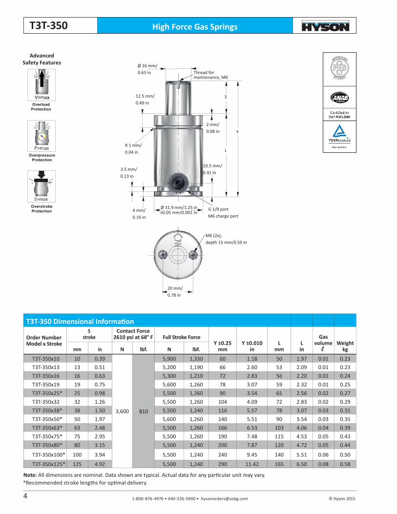
High Force Gas SpringsT3T-350
Note: All dimensions are nominal. Data shown are typical. Actual data for any particular unit may vary.
APPROVED
97/23/EC
Overload Protection
Overpressure Protection
Overstroke Protection
Advanced Safety Features
Thread for maintenance, M6
G 1/8 portM6 charge port
M6 (2x), depth 15 mm/0.59 in
2 mm/0.08 in
10.5 mm/0.41 in
Ø 16 mm/0.63 in
L
Y
S
Ø 31.9 mm/1.25 in±0.05 mm/0.001 in
20 mm/0.78 in
12.5 mm/0.49 in
R 1 mm/0.04 in
3.5 mm/0.13 in
4 mm/0.16 in
T3T-350 Dimensional Information
Order Number Model x Stroke
S stroke
Contact Force2610 psi at 68° F Full Stroke Force
Y ±0.25mm
Y ±0.010in
Lmm
Lin
Gasvolume Weight
kgmm in N lbf. N lbf.
T3T-350x10 10 0.39
3,600 810
5,900 1,330 60 1.18 50 1.97 0.01 0.23T3T-350x13 13 0.51 5,200 1,190 66 2.60 53 2.09 0.01 0.23T3T-350x16 16 0.63 5,300 1,210 72 2.83 56 2.20 0.01 0.24T3T-350x19 19 0.75 5,600 1,260 78 3.07 59 2.32 0.01 0.25T3T-350x25* 25 0.98 5,500 1,260 90 3.54 65 2.56 0.02 0.27T3T-350x32 32 1.26 5,500 1,260 104 4.09 72 2.83 0.02 0.29T3T-350x38* 38 1.50 5,500 1,240 116 5.57 78 3.07 0.03 0.31T3T-350x50* 50 1.97 5,600 1,260 140 5.51 90 3.54 0.03 0.35T3T-350x63* 63 2.48 5,500 1,260 166 6.53 103 4.06 0.04 0.39T3T-350x75* 75 2.95 5,500 1,260 190 7.48 115 4.53 0.05 0.43T3T-350x80* 80 3.15 5,500 1,240 200 7.87 120 4.72 0.05 0.44
T3T-350x100* 100 3.94 5,500 1,240 240 9.45 140 5.51 0.06 0.50
T3T-350x125* 125 4.92 5,500 1,240 290 11.42 165 6.50 0.08 0.58
4
*Recommended stroke lengths for optimal delivery
l
1-800-876-4976 • 440-526-5900 • [email protected] © Hyson 2015
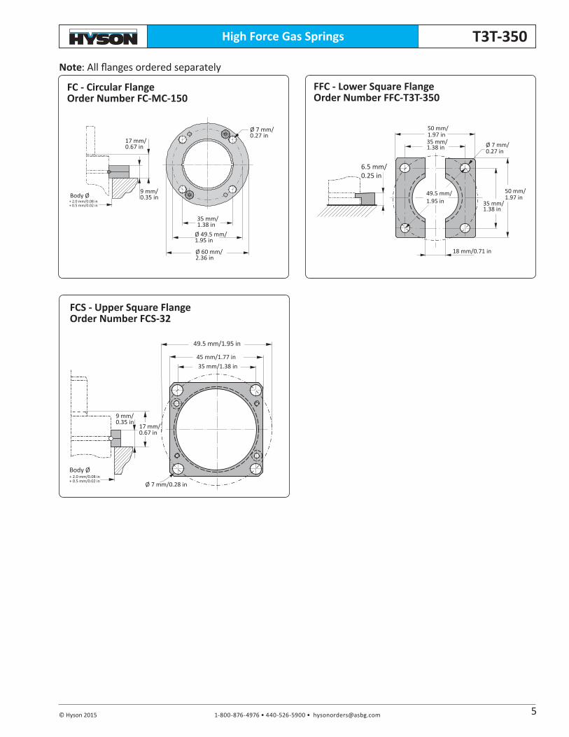
High Force Gas Springs T3T-350
FCS - Upper Square FlangeOrder Number FCS-32
Ø 7 mm/0.28 in
f
9 mm/0.35 in
45 mm/1.77 in35 mm/1.38 in
49.5 mm/1.95 in
17 mm/0.67 in
Body Ø+ 2.0 mm/0.08 in+ 0.5 mm/0.02 in
FC - Circular FlangeOrder Number FC-MC-150
Note: All flanges ordered separately
FFC - Lower Square FlangeOrder Number FFC-T3T-350
Ø 7 mm/0.27 in
17 mm/0.67 in
Body Ø
35 mm/1.38 in
Ø 49.5 mm/1.95 in
Ø 60 mm/2.36 in
9 mm/0.35 in
+ 2.0 mm/0.08 in+ 0.5 mm/0.02 in
18 mm/0.71 in
Ø 7 mm/0.27 in
6.5 mm/0.25 in
50 mm/1.97 in35 mm/1.38 in
49.5 mm/1.95 in
50 mm/1.97 in
35 mm/1.38 in
5

1-800-876-4976 • 440-526-5900 • [email protected] © Hyson 2015
High Force Gas SpringsT3T-500
APPROVED
97/23/EC
Overload Protection
Overpressure Protection
Overstroke Protection
Advanced Safety Features
G 1/8 portM6 charge port
2 mm/0.08 in
S
Ø 38 mm/1.49 in+0 mm/0 in- 0.2 mm/0.007 in
10.5 mm/0.41 in
Y
L
M6 (2x), depth 15 mm/0.59 in
25 mm/0.98 in
Thread for maintenance M6
Ø 20 mm/0.78 in
12.5 mm/0.49 in
R 1 mm/0.04 in
4 mm/0.16 in
4 mm/0.16 in
Note: All dimensions are nominal. Data shown are typical. Actual data for any particular unit may vary.*Recommended stroke lengths for optimal delivery
T3T-500 Dimensional Information
Order Number Model x Stroke
S stroke
Contact Force2175 psi at 68° F Full Stroke Force
Y ±0.25mm
Y ±0.010in
Lmm
Lin
Gasvolume Weight
kgmm in N lbf. N lbf.
T3T-500x10 10 0.39
4,700 1,055
7,200 1,620 60 2.36 50 1.97 0.01 0.33T3T-500x13 13 0.51 7,100 1,600 66 2.59 53 2.09 0.01 0.34T3T-500x16 16 0.63 7,200 1,620 72 2.83 56 2.20 0.02 0.36T3T-500x19 19 0.75 7,400 1,660 78 3.07 59 2.32 0.02 0.37T3T-500x25* 25 0.98 7,300 1,640 90 3.54 65 2.56 0.03 0.39T3T-500x32 32 1.26 7,200 1,620 104 4.09 72 2.83 0.03 0.42T3T-500x38* 38 1.50 7,200 1,620 116 4.57 78 3.07 0.04 0.44T3T-500x50* 50 1.97 7,200 1,620 140 5.51 90 3.54 0.05 0.49T3T-500x63* 63 2.48 7,200 1,620 166 6.53 103 4.05 0.06 0.54T3T-500x75* 75 2.95 7,100 1,600 190 7.48 115 4.53 0.07 0.58T3T-500x80* 80 3.15 7,100 1,600 200 7.87 120 4.72 0.08 0.60
T3T-500x100* 100 3.94 7,100 1,600 240 9.45 140 5.51 0.10 0.68
T3T-500x125* 125 4.92 7,100 1,600 290 11.42 165 4.50 0.12 0.77
6
l

1-800-876-4976 • 440-526-5900 • [email protected] © Hyson 2015
High Force Gas Springs T3T-500
FCS - Upper Square FlangeOrder Number FCS-250
FFC - Lower Square FlangeOrder Number FFC-T3T-500
18 mm/0.71 in
Ø 7 mm/0.27 in
6.5 mm/0.25 in
55 mm/2.16 in40 mm/1.57 in
56.6 mm/2.23 in
55 mm/2.16 in
40 mm/1.57 in
FC - Circular FlangeOrder Number FC-250
Note! All flanges ordered separately
Ø 7 mm/0.28 in
f
9 mm/0.35 in
52 mm/2.05 mm40 mm/1.57 in
56.5 mm/2.22 in
17 mm/0.67 in
+ 2.0 mm/0.08 in+ 0.5 mm/0.02 in
Body Ø
Ø 7 mm/0.27 in
17 mm/0.67 in
Body Ø + 2.0 mm/0.08 in+ 0.5 mm/0.02 in
40 mm/1.57 in
Ø 56.5 mm/2.22 in
Ø 68 mm/2.68 in
9 mm/0.35 in
7
1-800-876-4976 • 440-526-5900 • [email protected] © Hyson 2015
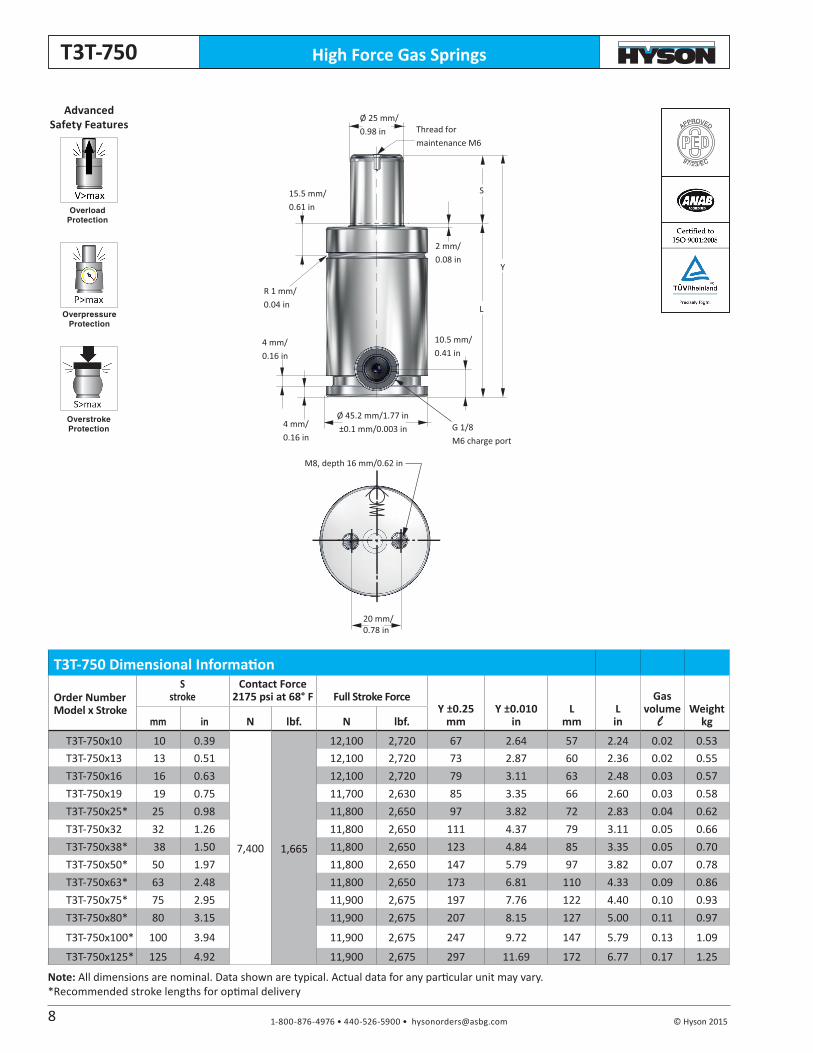
High Force Gas SpringsT3T-750
Note: All dimensions are nominal. Data shown are typical. Actual data for any particular unit may vary.*Recommended stroke lengths for optimal delivery
APPROVED
97/23/EC
Overload Protection
Overpressure Protection
Overstroke Protection
Advanced Safety Features Thread for
maintenance M6
G 1/8M6 charge port
Ø 25 mm/0.98 in
S
Y
L
Ø 45.2 mm/1.77 in ±0.1 mm/0.003 in
M8, depth 16 mm/0.62 in
20 mm/0.78 in
2 mm/0.08 in
10.5 mm/0.41 in
15.5 mm/0.61 in
R 1 mm/0.04 in
4 mm/0.16 in
4 mm/0.16 in
T3T-750 Dimensional Information
Order Number Model x Stroke
S stroke
Contact Force2175 psi at 68° F Full Stroke Force
Y ±0.25mm
Y ±0.010in
Lmm
Lin
Gasvolume Weight
kgmm in N lbf. N lbf.
T3T-750x10 10 0.39
7,400 1,665
12,100 2,720 67 2.64 57 2.24 0.02 0.53T3T-750x13 13 0.51 12,100 2,720 73 2.87 60 2.36 0.02 0.55T3T-750x16 16 0.63 12,100 2,720 79 3.11 63 2.48 0.03 0.57T3T-750x19 19 0.75 11,700 2,630 85 3.35 66 2.60 0.03 0.58T3T-750x25* 25 0.98 11,800 2,650 97 3.82 72 2.83 0.04 0.62T3T-750x32 32 1.26 11,800 2,650 111 4.37 79 3.11 0.05 0.66T3T-750x38* 38 1.50 11,800 2,650 123 4.84 85 3.35 0.05 0.70T3T-750x50* 50 1.97 11,800 2,650 147 5.79 97 3.82 0.07 0.78T3T-750x63* 63 2.48 11,800 2,650 173 6.81 110 4.33 0.09 0.86T3T-750x75* 75 2.95 11,900 2,675 197 7.76 122 4.40 0.10 0.93T3T-750x80* 80 3.15 11,900 2,675 207 8.15 127 5.00 0.11 0.97
T3T-750x100* 100 3.94 11,900 2,675 247 9.72 147 5.79 0.13 1.09
T3T-750x125* 125 4.92 11,900 2,675 297 11.69 172 6.77 0.17 1.25
8
l
1-800-876-4976 • 440-526-5900 • [email protected] © Hyson 2015
High Force Gas Springs T3T-750
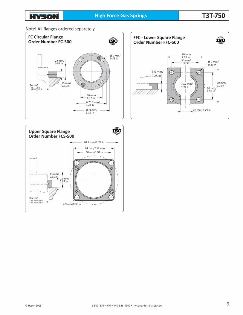
FFC - Lower Square FlangeOrder Number FFC-500
Ø 9 mm/0.35 in
f
13 mm/0.51 in
64 mm/2.52 mm50 mm/1.97 in
70.7 mm/2.78 in
22 mm/0.87 in
+ 2.0 mm/0.08 in+ 0.5 mm/0.02 in
Body Ø
20 mm/0.79 in
Ø 9 mm/0.35 in
6.5 mm/0.25 in
70 mm/2.75 in50 mm/1.97 in
70.7 mm/2.78 in
70 mm/2.75in
50 mm/1.97 in
FC Circular FlangeOrder Number FC-500
Ø 9 mm/0.35 in
22 mm/0.87 in
Body Ø + 2.0 mm/0.08 in+ 0.5 mm/0.02 in
50 mm/1.97 in
Ø 70.7 mm/2.78 in
Ø 86mm/3.39 in
13 mm/0.51 in
Note! All flanges ordered separately
Upper Square FlangeOrder Number FCS-500
9
1-800-876-4976 • 440-526-5900 • [email protected] © Hyson 2015
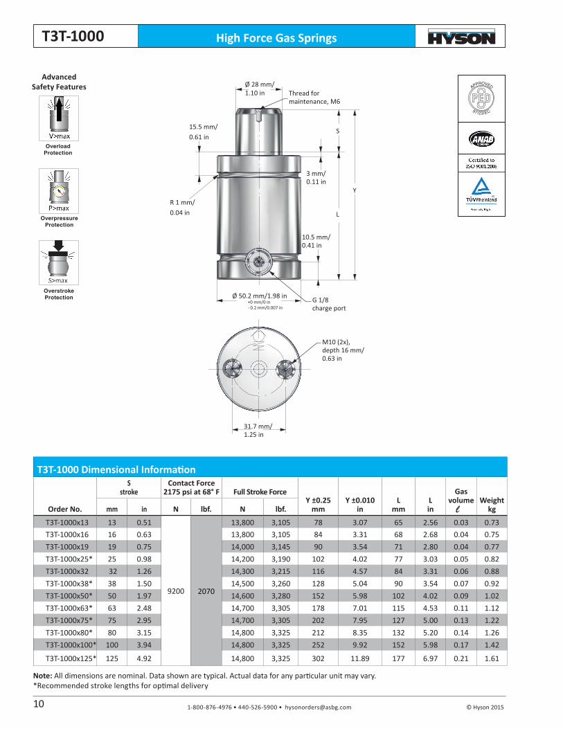
High Force Gas SpringsT3T-1000
Note: All dimensions are nominal. Data shown are typical. Actual data for any particular unit may vary.*Recommended stroke lengths for optimal delivery
APPROVED
97/23/EC
Overload Protection
Overpressure Protection
Overstroke Protection
Advanced Safety Features
Thread for maintenance, M6
10.5 mm/0.41 in
G 1/8 charge port
3 mm/0.11 in
M10 (2x), depth 16 mm/0.63 in
S
Ø 28 mm/1.10 in
Y
L
31.7 mm/1.25 in
Ø 50.2 mm/1.98 in +0 mm/0 in- 0.2 mm/0.007 in
15.5 mm/0.61 in
R 1 mm/0.04 in
T3T-1000 Dimensional Information
Order No.
S stroke
Contact Force2175 psi at 68° F Full Stroke Force
Y ±0.25mm
Y ±0.010in
Lmm
Lin
Gasvolume Weight
kgmm in N lbf. N lbf.
T3T-1000x13 13 0.51
9200 2070
13,800 3,105 78 3.07 65 2.56 0.03 0.73T3T-1000x16 16 0.63 13,800 3,105 84 3.31 68 2.68 0.04 0.75T3T-1000x19 19 0.75 14,000 3,145 90 3.54 71 2.80 0.04 0.77T3T-1000x25* 25 0.98 14,200 3,190 102 4.02 77 3.03 0.05 0.82T3T-1000x32 32 1.26 14,300 3,215 116 4.57 84 3.31 0.06 0.88T3T-1000x38* 38 1.50 14,500 3,260 128 5.04 90 3.54 0.07 0.92T3T-1000x50* 50 1.97 14,600 3,280 152 5.98 102 4.02 0.09 1.02T3T-1000x63* 63 2.48 14,700 3,305 178 7.01 115 4.53 0.11 1.12T3T-1000x75* 75 2.95 14,700 3,305 202 7.95 127 5.00 0.13 1.22T3T-1000x80* 80 3.15 14,800 3,325 212 8.35 132 5.20 0.14 1.26T3T-1000x100* 100 3.94 14,800 3,325 252 9.92 152 5.98 0.17 1.42
T3T-1000x125* 125 4.92 14,800 3,325 302 11.89 177 6.97 0.21 1.61
10
l
1-800-876-4976 • 440-526-5900 • [email protected] © Hyson 2015
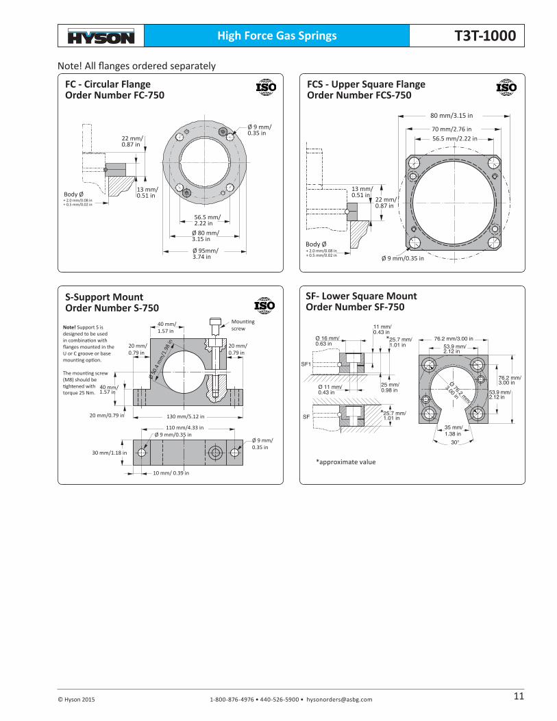
High Force Gas Springs T3T-1000
Ø 9 mm/0.35 in
f
13 mm/0.51 in
70 mm/2.76 in56.5 mm/2.22 in
80 mm/3.15 in
22 mm/0.87 in
+ 2.0 mm/0.08 in+ 0.5 mm/0.02 in
Body Ø
Ø 9 mm/0.35 in
22 mm/0.87 in
Body Ø + 2.0 mm/0.08 in+ 0.5 mm/0.02 in
56.5 mm/2.22 in
Ø 80 mm/3.15 in
Ø 95mm/3.74 in
13 mm/0.51 in
Note! Support S is designed to be used in combination with flanges mounted in the U or C groove or base mounting option.
The mounting screw (M8) should be tightened with torque 25 Nm.
Ø 9 mm/0.35 in
Ø 9 mm/0.35 in
10 mm/ 0.39 in
Ø 50
.4 m
m/1
.98
in
Mountingscrew
40 mm/1.57 in
20 mm/0.79 in
20 mm/0.79 in
30 mm/1.18 in
40 mm/1.57 in
20 mm/0.79 in
130 mm/5.12 in
110 mm/4.33 in
Note! All flanges ordered separately
Ø 11 mm/0.43 in
30°
Ø 16 mm/0.63 in
11 mm/0.43 in
25 mm/0.98 in
25.7 mm/1.01 in
76.2 mm/3.00 in53.9 mm/2.12 in
76.2 mm/3.00 in
53.9 mm/2.12 in
35 mm/1.38 in
25.7 mm/1.01 in
SF1
SF
Ø 76.2 mm
/
3.00 in
SF- Lower Square Mount Order Number SF-750
11
*approximate value
*
*
FC - Circular FlangeOrder Number FC-750
FCS - Upper Square FlangeOrder Number FCS-750
S-Support MountOrder Number S-750
1-800-876-4976 • 440-526-5900 • [email protected] © Hyson 2015
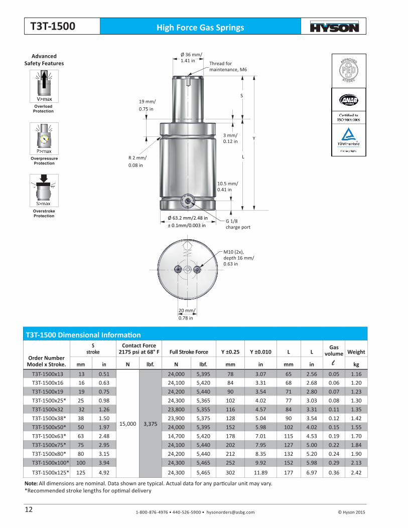
High Force Gas SpringsT3T-1500
Note: All dimensions are nominal. Data shown are typical. Actual data for any particular unit may vary.*Recommended stroke lengths for optimal delivery
APPROVED
97/23/EC
Overload Protection
Overpressure Protection
Overstroke Protection
Advanced Safety Features Thread for
maintenance, M6
G 1/8charge port
S
Ø 36 mm/1.41 in
Y
L
10.5 mm/0.41 in
3 mm/0.12 in
M10 (2x), depth 16 mm/0.63 in
20 mm/0.78 in
19 mm/0.75 in
R 2 mm/0.08 in
Ø 63.2 mm/2.48 in ± 0.1mm/0.003 in
T3T-1500 Dimensional Information
Order NumberModel x Stroke.
S stroke
Contact Force2175 psi at 68° F Full Stroke Force Y ±0.25 Y ±0.010 L L
Gasvolume
Weight
mm in N lbf. N lbf. mm in mm in kg
T3T-1500x13 13 0.51
15,000 3,375
24,000 5,395 78 3.07 65 2.56 0.05 1.16T3T-1500x16 16 0.63 24,100 5,420 84 3.31 68 2.68 0.06 1.20T3T-1500x19 19 0.75 24,200 5,440 90 3.54 71 2.80 0.07 1.23T3T-1500x25* 25 0.98 24,300 5,365 102 4.02 77 3.03 0.08 1.30T3T-1500x32 32 1.26 23,800 5,355 116 4.57 84 3.31 0.11 1.35T3T-1500x38* 38 1.50 23,900 5,375 128 5.04 90 3.54 0.12 1.42T3T-1500x50* 50 1.97 24,000 5,395 152 5.98 102 4.02 0.15 1.55T3T-1500x63* 63 2.48 14,700 5,420 178 7.01 115 4.53 0.19 1.70T3T-1500x75* 75 2.95 24,100 5,440 202 7.95 127 5.00 0.22 1.84T3T-1500x80* 80 3.15 24,200 5,440 212 8.35 132 5.20 0.24 1.90T3T-1500x100* 100 3.94 24,300 5,465 252 9.92 152 5.98 0.29 2.13
T3T-1500x125* 125 4.92 24,300 5,465 302 11.89 177 6.97 0.36 2.42
12
l

1-800-876-4976 • 440-526-5900 • [email protected] © Hyson 2015
High Force Gas Springs T3T-1500
Ø 11 mm/0.43 in
f
16 mm/0.63 in
Ø 90.5 mm/3.56 in
80 mm/3.15 in64 mm/2.52 in
27 mm/1.06 in
+ 2.0 mm/0.08 in+ 0.5 mm/0.02 in
Body Ø
Note! All flanges ordered separately
SFX - Lower Square Mount Flange Order Number SFX-1500
Ø 11 mm/0.43 in
30°
Ø 18 mm/0.71 in
11 mm/0.43 in
25.7 mm/1.01 in
25 mm/0.98 in
100 mm/3.94 in73.5 mm/2.89 in
100 mm/3.94 in
73.5 mm/2.89 in
49 mm/1.93 in
25.7 mm/1.01 in
Ø 104 mm
/
4.09 in
SF1
SF
13
Ø 11 mm/0.43 in
Body Ø
f
16 mm/0.63 in
Ø 104 mm/4.09 in
90 mm/3.54 in73.5 mm/2.89 in
27 mm/1.06 in
+ 2.0 mm/0.08 in+ 0.5 mm/0.02 in
*approximate value
*
*
FCX-Upper Square FlangeOrder Number FCX-1500
FCS-Upper Square FlangeOrder Number FCSX-1500
1-800-876-4976 • 440-526-5900 • [email protected] © Hyson 2015
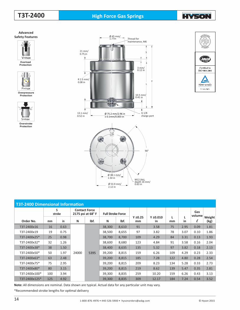
High Force Gas SpringsT3T-2400
APPROVED
97/23/EC
Overload Protection
Overpressure Protection
Overstroke Protection
Advanced Safety Features Thread for
maintenance, M6
G 1/8 charge port
S
YL
Ø 53.9 mm/2.12 in
90°
Ø 45 mm/1.77in
10.5 mm/0.41 in
3 mm/0.12 in
M12 (4x), depth 16 mm/0.63 in
Ø 75.2 mm/2.96 in ± 0.1mm/0.003 in
Ø 38.1 mm/1.50 in
21 mm/0.75 in
R 2.5 mm/0.08 in
13.1 mm/0.52 in
T3T-2400 Dimensional Information
Order No.
S stroke
Contact Force2175 psi at 68° F Full Stroke Force
Y ±0.25mm
Y ±0.010in
Lmm
Lin
Gas volume l
Weight (kg)mm in N lbf. N lbf.
T3T-2400x16 16 0.63
24000 5395
38,300 8,610 91 3.58 75 2.95 0.09 1.81T3T-2400x19 19 0.75 38,500 8,655 97 3.82 78 3.07 0.10 1.86T3T-2400x25* 25 0.98 38,700 8,700 109 4.29 84 3.31 0.13 1.93T3T-2400x32* 32 1.26 38,600 8,680 123 4.84 91 3.58 0.16 2.04T3T-2400x38* 38 1.50 38,400 8,635 135 5.32 97 3.82 0.18 2.13T3T-2400x50* 50 1.97 39,200 8,815 159 6.26 109 4.29 0.23 2.33T3T-2400x63* 63 2.48 39,200 8,815 185 7.28 122 4.80 0.28 2.54T3T-2400x75* 75 2.95 39,200 8,815 209 8.23 134 5.28 0.33 2.73T3T-2400x80* 80 3.15 39,200 8,815 219 8.62 139 5.47 0.35 2.81T3T-2400x100* 100 3.94 39,300 8,835 259 10.20 159 6.26 0.43 3.13T3T-2400x125* 125 4.92 39,300 8,835 309 12.17 184 7.24 0.54 3.52
Note: All dimensions are nominal. Data shown are typical. Actual data for any particular unit may vary.
*Recommended stroke lengths for optimal delivery
14
1-800-876-4976 • 440-526-5900 • [email protected] © Hyson 2015
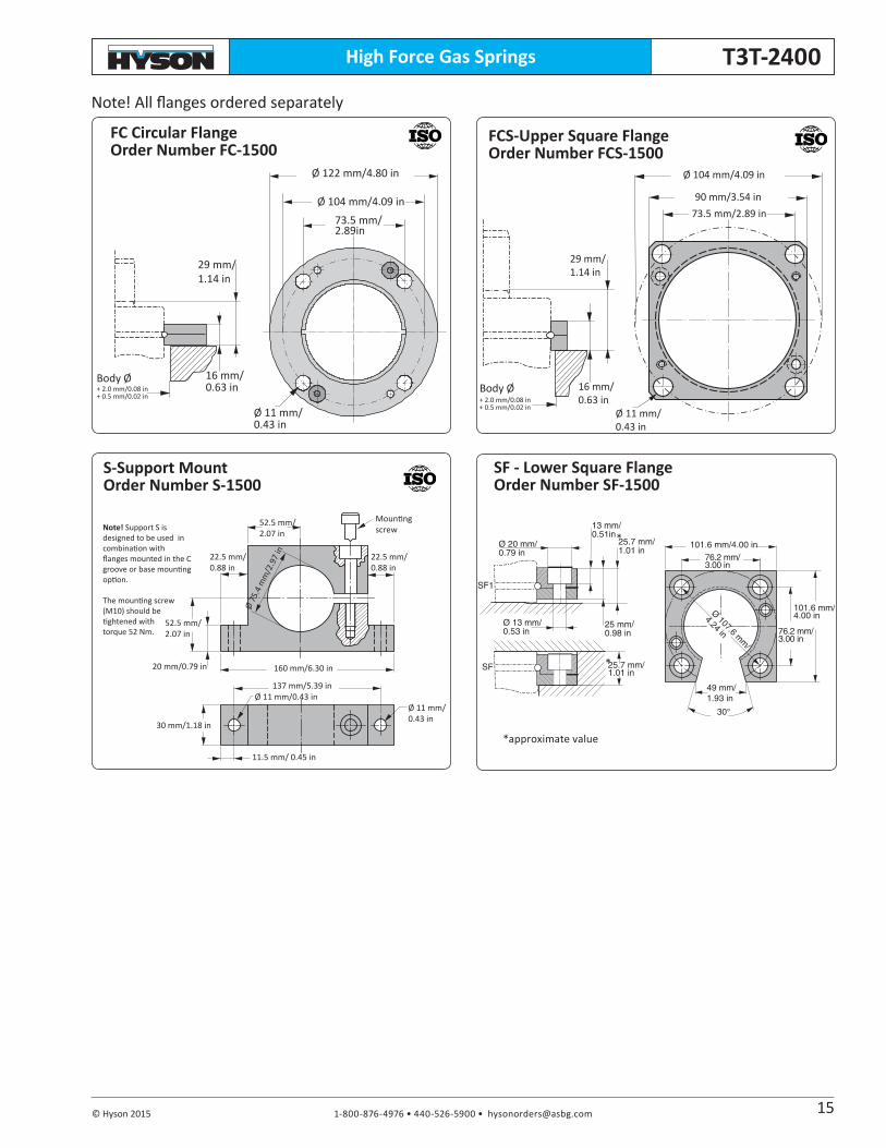
High Force Gas Springs T3T-2400
Ø 11 mm/0.43 in
f
16 mm/0.63 in
Ø 104 mm/4.09 in
90 mm/3.54 in73.5 mm/2.89 in
29 mm/1.14 in
+ 2.0 mm/0.08 in+ 0.5 mm/0.02 in
Body Ø+ 2.0 mm/0.08 in+ 0.5 mm/0.02 in
Ø 11 mm/0.43 in
Body Ø
f
16 mm/0.63 in
Ø 122 mm/4.80 in
29 mm/1.14 in
Ø 104 mm/4.09 in73.5 mm/2.89in
Note! Support S is designed to be used in combination with flanges mounted in the C groove or base mounting option.
The mounting screw (M10) should be tightened with torque 52 Nm.
Ø 11 mm/0.43 in
11.5 mm/ 0.45 in
Ø 75
.4 m
m/2
.97
in
Mountingscrew
22.5 mm/0.88 in
20 mm/0.79 in
30 mm/1.18 in
52.5 mm/2.07 in
160 mm/6.30 in
137 mm/5.39 in
22.5 mm/0.88 in
52.5 mm/2.07 in
Ø 11 mm/0.43 in
Note! All flanges ordered separately
SF - Lower Square FlangeOrder Number SF-1500
Ø 13 mm/0.53 in
30°
Ø 20 mm/0.79 in
13 mm/0.51in
25.7 mm/1.01 in
25 mm/0.98 in
101.6 mm/4.00 in76.2 mm/3.00 in
101.6 mm/4.00 in
76.2 mm/3.00 in
49 mm/1.93 in
25.7 mm/1.01 in
SF1
SF
Ø 107.6 mm
/
4.24 in
15
*approximate value
*
*
FC Circular FlangeOrder Number FC-1500
FCS-Upper Square FlangeOrder Number FCS-1500
S-Support MountOrder Number S-1500

1-800-876-4976 • 440-526-5900 • [email protected] © Hyson 2015
High Force Gas SpringsT3T-4200
APPROVED
97/23/EC
Overload Protection
Overpressure Protection
Overstroke Protection
Advanced Safety Features
S
YL
90°
Thread for maintenance, M8
G 1/8 charge port
Ø 76.2 mm/3.0 in
Ø 60 mm/2.36 in
10.5 mm/0.41 in
3 mm/0.12 in
M12 (4x), depth 16 mm/0.63 in
Ø 95.2 mm/3.74 in ± 0.1mm/0.003 in
Ø 53.9 mm/2.12 in
24 mm/0.94 in
R 2.5 mm/0.08 in
13.1 mm/0.52 in
Note: All dimensions are nominal. Data shown are typical. Actual data for any particular unit may vary.*Recommended stroke lengths for optimal delivery
T3T-4200 Dimensional Information
Order No.
S stroke
Contact Force2175 psi at 68° F Full Stroke Force
Y ±0.25mm
Y ±0.010in
Lmm
Lin
Gas volume l
Weight (kg)mm in N lbf. N lbf.
T3T-4200x16 16 0.63
42000 9440
61,700 13,870 94 3.70 78 3.07 0.15 3.03T3T-4200x19 19 0.75 63,700 14,320 100 3.94 81 3.19 0.18 3.10T3T-4200x25* 25 0.98 60,800 13,670 112 4.41 87 3.43 0.26 3.18T3T-4200x32 32 1.26 64,300 14,555 126 4.96 94 3.70 0.30 3.35T3T-4200x38* 38 1.50 65,800 14,795 138 5.43 100 3.94 0.32 3.50T3T-4200x50* 50 1.97 67,000 15,065 162 6.38 112 4.41 0.40 3.79T3T-4200x63* 63 2.48 67,800 15,245 188 7.40 125 4.92 0.49 4.12T3T-4200x75* 75 2.95 68,000 15,290 212 8.35 137 5.39 0.58 4.42T3T-4200x80* 80 3.15 68,600 15,425 222 8.74 142 5.59 0.61 4.52T3T-4200x100* 100 3.94 69,100 15,535 262 10.32 162 6.38 0.74 5.03T3T-4200x125* 125 4.92 69,600 15,645 312 12.28 187 7.36 0.91 5.64
16
1-800-876-4976 • 440-526-5900 • [email protected] © Hyson 2015
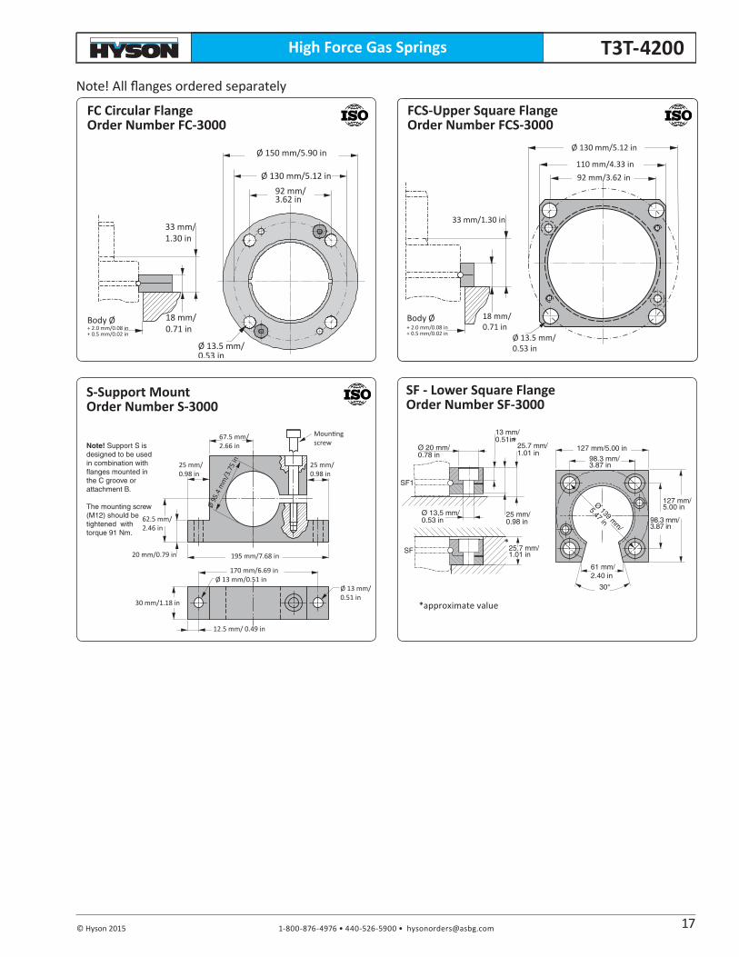
High Force Gas Springs T3T-4200
Ø 13.5 mm/0.53 in
f
18 mm/0.71 in
Ø 130 mm/5.12 in
110 mm/4.33 in92 mm/3.62 in
33 mm/1.30 in
+ 2.0 mm/0.08 in+ 0.5 mm/0.02 in
Body Ø
Note! All flanges ordered separately
+ 2.0 mm/0.08 in+ 0.5 mm/0.02 in
Ø 13.5 mm/0.53 in
Body Ø
fØ 150 mm/5.90 in
33 mm/1.30 in
Ø 130 mm/5.12 in92 mm/3.62 in
18 mm/0.71 in
Note! Support S is designed to be used in combination with flanges mounted in the C groove or attachment B.
The mounting screw (M12) should be tightened with torque 91 Nm.
Ø 13 mm/0.51 in
12.5 mm/ 0.49 in
Ø 95
.4 m
m/3
.75
in
Mountingscrew
25 mm/0.98 in
20 mm/0.79 in
30 mm/1.18 in
67.5 mm/2.66 in
195 mm/7.68 in
170 mm/6.69 in
25 mm/0.98 in
62.5 mm/2.46 in
Ø 13 mm/0.51 in
SF - Lower Square FlangeOrder Number SF-3000
Ø 13,5 mm/0.53 in
30°
Ø 20 mm/0.78 in
13 mm/0.51in
25.7 mm/1.01 in
25 mm/0.98 in
127 mm/5.00 in98.3 mm/3.87 in
127 mm/5.00 in
98.3 mm/3.87 in
61 mm/2.40 in
25.7 mm/1.01 in
Ø 139 mm
/
5.47 in
SF1
SF
17
*approximate value
*
*
FC Circular FlangeOrder Number FC-3000
FCS-Upper Square FlangeOrder Number FCS-3000
S-Support MountOrder Number S-3000
1-800-876-4976 • 440-526-5900 • [email protected] © Hyson 2015
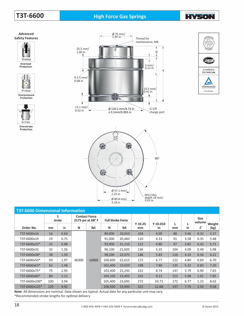
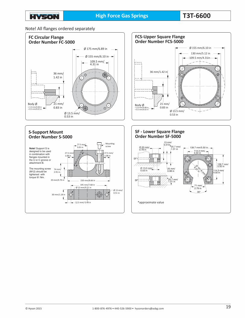
High Force Gas SpringsT3T-6600
S
YL
90°
Thread for maintenance, M8
G 1/8charge port
Ø 80.8 mm/3.18 in
Ø 75 mm/2.95 in
10.5 mm/0.41 in
3 mm/0.12 in
M12 (4x), depth 16 mm/0.63 in
Ø 120.2 mm/4.73 in ± 0.1mm/0.003 in
Ø 57.1 mm/2.25 in
25.5 mm/1.00 in
R 2.5 mm/0.08 in
13.1 mm/0.52 in
APPROVED
97/23/EC
Overload Protection
Overpressure Protection
Overstroke Protection
Advanced Safety Features
T3T-6600 Dimensional Information
Order No.
S stroke
Contact Force2175 psi at 68° F Full Stroke Force
Y ±0.25mm
Y ±0.010in
Lmm
Lin
Gas volume l
Weight (kg)mm in N lbf. N lbf.
T3T-6600x16 16 0.63
66300 14905
89,000 20,010 104 4.09 88 3.46 0.32 5.37T3T-6600x19 19 0.75 91,000 20,460 110 4.33 91 3.58 0.35 5.48T3T-6600x25* 25 0.98 93,900 21,110 122 4.80 97 3.82 0.42 5.71T3T-6600x32 32 1.26 96,100 21,605 136 5.35 104 4.09 0.49 5.98T3T-6600x38* 38 1.50 98,200 22,075 148 5.83 110 4.33 0.56 6.21T3T-6600x50* 50 1.97 100,600 22,615 172 6.77 122 4.80 0.69 6.70T3T-6600x63* 63 2.48 102,400 23,020 198 7.80 135 5.32 0.83 7.20T3T-6600x75* 75 2.95 103,400 23,245 222 8.74 147 5.79 0.90 7.65T3T-6600x80* 80 3.15 104,100 23,405 232 9.13 152 5.98 1.01 7.85T3T-6600x100* 100 3.94 105,400 23,695 272 10.71 172 6.77 1.23 8.62T3T-6600x125* 125 4.92 106,500 23,945 322 12.68 197 7.76 1.50 9.58
Note: All dimensions are nominal. Data shown are typical. Actual data for any particular unit may vary.*Recommended stroke lengths for optimal delivery
18
1-800-876-4976 • 440-526-5900 • [email protected] © Hyson 2015
High Force Gas Springs T3T-6600
Ø 13,5 mm/0.53 in
30°
Ø 20 mm/0.78 in
13 mm/0.51in
25.7 mm/1.01 in
25 mm/0.98 in
139.7 mm/5.50 in114.3 mm/4.50 in
139.7 mm/5.50 in
114.3 mm/4.50 in
71 mm/2.79 in
25.7 mm/1.01 in
Ø 161.8 mm
/
6.37 in
SF1
SF
+ 2.0 mm/0.08 in+ 0.5 mm/0.02 in
Ø 13.5 mm/0.53 in
Body Ø
f
Ø 175 mm/6.89 in
36 mm/1.42 in
Ø 155 mm/6.10 in109.5 mm/4.31 in
21 mm/0.83 in
Ø 13.5 mm/0.53 in
f
21 mm/0.83 in
Ø 155 mm/6.10 in
130 mm/5.12 in109.5 mm/4.31in
36 mm/1.42 in
+ 2.0 mm/0.08 in+ 0.5 mm/0.02 in
Body Ø
Note! Support S is designed to be used in combination with flanges mounted in the U or C groove or attachment B.
The mounting screw (M12) should be tightened with torque 91 Nm.
Ø 13 mm/0.51 in
12.5 mm/ 0.49 in
Ø 12
0.4
mm
/3.7
2 in
Mountingscrew
27.5 mm/1.08 in
20 mm/0.79 in
30 mm/1.18 in
77.5 mm/3.05 in
220 mm/8.66 in
195 mm/7.68 in
27.5 mm/1.08 in
74 mm/2.91 in
Ø 13 mm/0.51 in
Note! All flanges ordered separately
19
*approximate value
*
*
SF - Lower Square FlangeOrder Number SF-5000
FC Circular FlangeOrder Number FC-5000
FCS-Upper Square FlangeOrder Number FCS-5000
S-Support MountOrder Number S-5000

1-800-876-4976 • 440-526-5900 • [email protected] © Hyson 2015
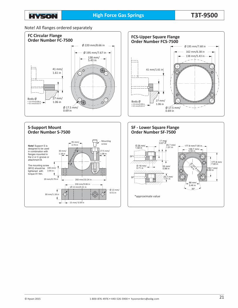
High Force Gas SpringsT3T-9500
S
YL
90°
Thread for maintenance, M8
G 1/8charge port
Ø 100 mm/3.94 in
Ø 90 mm/3.54 in
10.5 mm/0.41 in
3 mm/0.12 in
M12 (4x), depth 16 mm/0.63 in
Ø 150.2 mm/5.91 in ± 0.1mm/0.003 in
Ø 70.7 mm/2.78 in
27.5 mm/1.08 in
R 2.5 mm/0.08 in
13.1 mm/0.52 in
T3T-9500 Dimensional Information
Order No.
S stroke
Contact Force2175 psi at 68° F
Full Stroke Force
Y ±0.25mm
Y ±0.010in
Lmm
Lin
Gas volume l
Weight (kg)mm in N lbf. N lbf.
T3T-9500x19 19 0.75
95000 21360
135,000 30,350 116 4.57 97 3.82 0.49 9.91T3T-9500x25* 25 0.98 139,000 31,250 128 5.04 103 4.06 0.58 10.29T3T-9500x32 32 1.26 142,000 31,925 142 5.59 110 4.33 0.70 10.72T3T-9500x38* 38 1.50 143,000 32,150 154 6.06 116 4.57 0.80 11.10T3T-9500x50* 50 1.97 146,000 32,825 178 7.01 128 5.04 0.99 11.84T3T-9500x63* 63 2.48 148,000 33,275 204 8.03 141 5.55 1.20 12.66T3T-9500x75* 75 2.95 149,000 33,500 228 8.98 153 6.02 1.39 13.41T3T-9500x80* 80 3.15 150,000 33,725 238 9.37 158 6.22 1.47 13.72T3T-9500x100* 100 3.94 151,000 33,950 278 10.94 178 7.01 1.79 14.97T3T-9500x125* 125 4.92 152,000 34,175 328 12.91 203 7.99 2.20 16.54
Note: All dimensions are nominal. Data shown are typical. Actual data for any particular unit may vary.*Recommended stroke lengths for optimal delivery
APPROVED
97/23/EC
Overload Protection
Overpressure Protection
Overstroke Protection
Advanced Safety Features
20
1-800-876-4976 • 440-526-5900 • [email protected] © Hyson 2015
High Force Gas Springs T3T-9500
Ø 18 mm/0.71 in
30°
Ø 26 mm/1.02 in
17 mm/0.67 in
25.7 mm/1.01 in
25 mm/0.98 in
177.8 mm/7.00 in139.7 mm/5.50 in
177.8 mm/7.00 in
88 mm/3.46 in
25.7 mm/1.01 in
139.7 mm/5.50 in
Ø 197.8 mm
/
7.78 in
SF1
SF
+ 2.0 mm/0.08 in+ 0.5 mm/0.02 in
Ø 17.5 mm/0.69 in
Body Ø
f
Ø 220 mm/8.66 in
41 mm/1.61 in
Ø 195 mm/7.67 in138 mm/5.43 in
27 mm/1.06 in
f
27 mm/1.06 in
Ø 195 mm/7.68 in
162 mm/6.38 in138 mm/5.43 in
41 mm/1.61 in
Ø 17.5 mm/0.69 in
+ 2.0 mm/0.08 in+ 0.5 mm/0.02 in
Body Ø
Note! Support S is designed to be used in combination with flanges mounted in the U or C groove or attachment B.
The mounting screw (M12) should be tightened with torque 91 Nm.
Ø 13 mm/0.51 in
15 mm/ 0.59 in
Ø 15
0.4
mm
/3.9
2 in
Mountingscrew
30 mm/1.18 in
20 mm/0.79 in
30 mm/1.18 in
95 mm/3.74 in
260 mm/10.24 in
230 mm/9.06 in
27.5 mm/1.08 in
100 mm/3.94 in
Ø 13 mm/0.51 in
Note! All flanges ordered separately
21
*approximate value
*
*
SF - Lower Square FlangeOrder Number SF-7500
FC Circular FlangeOrder Number FC-7500
FCS-Upper Square FlangeOrder Number FCS-7500
S-Support MountOrder Number S-7500

©Hyson 0515 T3T-2k-0315
M E TA L F O R M I N G S O L U T I O N S
www.HysonProducts.comE-mail: [email protected]
™
U.S.A. Headquarters • 10367 Brecksville Road • Brecksville, OH 44141 USA • Tel: 800-876-4976, 440-526-5900