Embed Size (px)
Citation preview

NASA-CR-190656
HIGH-FREQUENCY TECHNIQUES FOR RCS PREDICTION
OF PLATE GEOMETRIES
Semiannual Progress Report
Constantine A. Balanis and Lesley A. Polka
February 1, 1992 - July 31, 1992
(NASA-CR-19065H) HIGH-FREQUENCY N92-31273
T_CHNIQUffS FGR RCS PRffO[CTION OF
PLATE GEC_ETRTES Semiannual
Progress Report, ] Feb. - 31Jul. Unclas
1992 (Arizona State Univ.) 2I p
G3/32 0115497
Telecommunications Research Center
College of Engineering and Applied Science
Arizona State University
Tempe, AZ 85287-7206
Grant No. NAG-I-562
National Aeronautics and Space Administration
Langley Research Center
Hampton, VA 23665
https://ntrs.nasa.gov/search.jsp?R=19920022029 2018-05-13T09:54:36+00:00Z

I" ,i,,_. i. v i ,v I 'i
HIGH-FREQUENCY TECHNIQUES FOR RCS PREDICTION
OF PLATE GEOMETRIES
Semiannual Progress Report
Constantine A. Balanis and Lesley A. Polka
February 1, 1992 - July 31, 1992
3,
Telecommunications Research Center
College of Engineering and Applied Science
Arizona State University
Tempe, AZ 85287-7206
Grant No. NAG-I-562
National Aeronautics and Space Administration
Langley Research Center
Hampton, VA 23665

Abstract
This report presents hard polarization diffraction coefficients for the
special case of a wedge that is coated with a lossy dielectric on one
face and is perfectly conducting on the other face. Expressions for
plane-wave incidence, far-field observation; for cylindrical-wave inci-
dence, far-field observation; and for plane-wave incidence, near-field
observation are presented for regular diffractions. In addition, terms
for surface-wave and surface-wave transition fields are presented. These
expressions are derived from the UTD coefficients for a generalized
impedance wedge and are simplified for rapid calculation for the case
of one perfectly conducting face. Results from a first-order model for a
coated, rectangular plate are examined; and potential problems in ex-
tending this modeling approach to more complicated coated structures
are identified.

I. INTRODUCTION
One of the most relevant topics in the area of high-frequency asymptotic
techniques for scattering prediction is the development of accurate theories for per-
fectly conducting geometries covered with thin, lossy coatings. Techniques such as
GTD/UTD [1], [2] and PTD [3], [4] have reached a high level of sophistication and
maturity in the realm of perfectly conducting geometries. Furthermore, work on
the UTD for the dielectric wedge has advanced to the point that general, compu-
tationally tractable coefficients are available for all wedge angles [.5] - [7] and have
been applied to practical geometries [8]. Developing UTD expressions for coated
geometries is an important follow-up topic as coated geometries have more prac-
tical applications than the more ideal perfectly conducting and dielectric wedge
geometries. Practical applications of the coated geometry are in low-observable
vehicles, collision-avoidance systems, and communications satellites.
The most difficult inherent problem in accurately modeling coated structures
is developing accurate, easily implemented, computationally fast expressions for
the coating impedance. Previous reports [9] - [13] have explored methods for
applying the UTD impedance wedge coefficients to a coated wedge and a coated
plate. The coefficients have successfully been adapted and simplified for the special
case of plane-wave incidence, far-field observation, hard polarization; and these
coefficients have been used to develop a first-order, hard polarization model for
the coated plate that agrees quite well with experimental results considering the
primitiveness of the model [13].
This report continues in this area by presenting UTD expressions for the hard
polarization case for regular diffractions for plane-wave incidence, far-field obser-
vation; cylindrical-wave incidence from a source at a finite distance, far-field obser-
vation; and plane-wave incidence, near-field observation. Furthermore, expressions

for surfacewavesand surface-wavetransition fields arealso given. Resultsfrom a
first-order model usingthesediffraction coefficientsfor a coated,rectangular plate
are presentedand discussed.
II. THEORY AND RESULTS
A. Problem Geometries and Parameters
The two geometries analyzed in this report are shown in Figs. 1 and 2. The
impedance wedge shown in Fig. 1 is the two-dimensional canonical, infinite wedge
for which the impedance UTD diffraction coefficients are derived. Fig. 1 demon-
strates the plane-wave incidence, far-field observation case with incidence angle,
_b', and observation angle, ¢. Cylindrical-wave incidence from a source at a fi-
nite distance, p', from the edge of the wedge will also be considered when the
observation point is in the far field. The reciprocal case of plane-wave incidence,
observation at a finite distance, p, from the wedge edge will also be included. The
interior angle of the wedge is designated as (2 - n)Tr so that, for example, a half
plane is designated by a wedge parameter of n = 2. The top face is face "0" and
the bottom is face "n".
The research in this report is primarily concerned with thin coatings on per-
fectly conducting surfaces so that the wedge geometry analyzed in the report has
a perfectly conducting "n" face. The parameter used to describe the wedge faces
is the surface impedance, 77. For the perfectly conducting "n" face the surface
impedance is zero. The impedance of the "0" face is not so simply represented.
Future work will explore higher-order boundary conditions and other methods for
modeling a coating on a perfectly conducting surface; however, this report uses a
shorted-transmission-line approximation for the coating impedance. This is accu-
rate near and at normal incidence to the surface and is a relatively simple model
3

to incorporate into the UTD diffraction coefficients. The equivalent impedance
of the coated "0" face normalizedwith respectto the impedanceof free-spaceis
representedas:
j _ tan(2_" _t) ( 1)r]° _ V £ro
where/% and e, 0 are the relative permeability and the relative permittivity, re-
spectively, of the "0" face; and t is the coating thickness in free-space wavelengths.
The equivalent surface impedance for each of the wedge faces is used to deter-
mine the Brewster angle, 0, for that surface, where the Brewster angle is the angle
at which no reflection is present. The Brewster angle is polarization dependent
and is given by:
Hard Polarization
0 = sin-l(r/) (2)
Soft Polarization
O----sin-'rt is the impedance of the surface normalized with respect to the free-space
impedance. Since the coatings in this study are lossy and thus have complex
permeabilities, the Brewster angles are also complex.
The coated, rectangular plate model is shown in Fig. 2. The width of the
plate is w, and the length is L; the coating thickness is t. The incidence angle
with respect to the x-y axis is ¢', and the observation angle is ¢. The incidence
and observation angles with respect to the left edge of the plate are ¢_ and 4'1,
respectively. With respect to the right edge, the incidence and observation angles
4

are _ and ¢2, respectively.
B. Coefficients for Hard Polarization
1. Plane-Wave Incidence, Far-Field Observation
The general UTD diffraction coefficient is given in [14] as:
D(p,¢',¢,Oo, O,_,n)_e-#} C_p(-_r + v__¢) sin(-_) + sin(_)
¢(-_- ¢')sin(_-) + sin(_)
X cot 2n F [kp (1 + COS --
O(Tr + -_ - ¢) sin(_) + sin(_)
' "_ - sin(__(T ¢') sin(_-_ -5) + )
xcot(rc-_-)F[kp(l+cos(t3--2n_rNZ))]
¢(- _- + _ - ¢) sin(_) - sin(_)
"" - sin(_)(T ¢') sin(_) +
xcot 2n ]F[kp(l+cos(3+-2n_rN+))]
_,(Tr + -_ ¢) sin(-_) - sin(_)
_/,(v__¢,) sin(-_)+sin(_)
× cot C r - #+2n )F[kp(l+cos(3+-2nTrN+))]}(4)
where
3 5 = ¢ + ¢' (5)
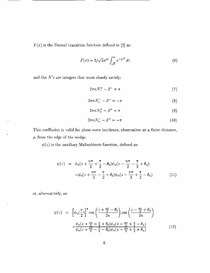
F(x) is the Fresnel transition function defined in [2] as:
F(x) = 2jvGe j* [_e -j'_ drd_
(6)
and the N's are integers that most closely satisfy:
27rnN +_- t3- = 7r (r)
2rrn N- /3--- -- _ -- 7(
2_,,N+ -/3+ =
2_nN+ -/3 + = -u
(s)
(9)
(lO)
This coet_ceint is valid for plane-wave incidence, observation at a finite distance,
p, from the edge of the wedge.
_b(z) is the auxiliary Maliuzhinets function, defined as:
7"/71" 7i" rtTr 71"
_,(:) = ¢.(z + 5- + g - Oo)_,.(z 2 2 + 0.)
I"/,7i" 7t" nTl" 71"
x¢,_(zq- 2 2 q-O°)_l'"(z-Tq--2-O_) (11)
or, alternatively, as:
g,(z) = cos 2n cos 2n
2 _ °c Oo)@_(z - _- -I- -ff (12)- 0.)
6
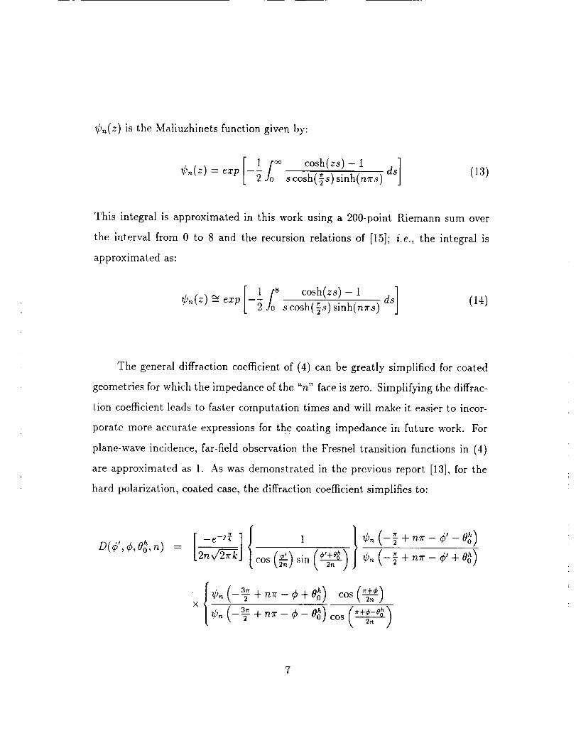
_b,_(z)is the Maliuzhinets function given by:
[ osh z*,-1]_,_(z) = ezp - scosh(-_s)sinh(nrrs) ds (13)
This integral is approximated in this work using a 200-point Riemann sum over
the interval from 0 to 8 and the recursion relations of [15]; i.e., the integral is
approximated as:
[ lf0S cosh(zs)-i ]_,_(z) _- exp --_ 8cosh(_s)sinh(n_rs) ds (14)
The general diffraction coefficient of (4) can be greatly simplified for coated
geometries for which the impedance of the "n" face is zero. Simplifying the diffrac-
tion coefficient leads to faster computation times and will make it easier to incor-
porate more accurate expressions for the coating impedance in future work. For
plane-wave incidence, far-field observation the Fresnel transition functions in (4)
are approximated as 1. As was demonstrated in the previous report [13], for the
hard polarization, coated case, the diffraction coefficient simplifies to:
D(¢, _,O_o,n)-
2n_J cos (_) sin k, 2. j
\2n}
× f.+,-O.o_
7

-Co_ (_'+_eo_cot(_ +_-
(0,0o )(,h ('+)1- ,__+eo_ _++sin cos 2n J cot 2n
_o(_+_- _+0_)cos(_)
x [cos (_b'_nO°h) sin (4/2+nOh) cot (r _?- )
0o ) } ,15,+sin(_'L cos
This simplified version of the impedance-wedge diffraction coefficient is analogous
to the Keller GTD diffraction coefficient [1] for the perfectly conducting wedge.
2. Plane-Wave Incidence, Observation at a Finite Distance
In order to incorporate higher-order diffraction terms into target models, e. g. , the
coated strip of Fig. 2, a simplified version of (4) is needed in which the Brewster
angle for the "n" face is set to 0. Substituting 0N = 0 and using the identity from
(12), the resulting diffraction coefficient is:
[ -e -_{D(¢"¢'°_°'n) = [2_
cos(_)sin\ 2_ j
_o(-_ +_- _'-oo_)_o(-_+_-_'+0o _)
-0o h (qS'_+ Ooh'_cot (rr + #-
,o(-_;+_-,+00 _) cosrm'_x ..... _ 2,., ,,
T+¢-O ho_TVvo_; _cos(_)
×_[k_(1+cos/_--2n.N_+t)]
2n cos\ 2n ]c°t 2n
+o(_+..- ++Oo_)co,(_)
x[cos(4D'-Ooh)sin+Ooh' ×_[_,'0+co,lj-- _,,.N-/)]
(_'-Oo_)(+'+0o_)+sin k, 2n cos 2n
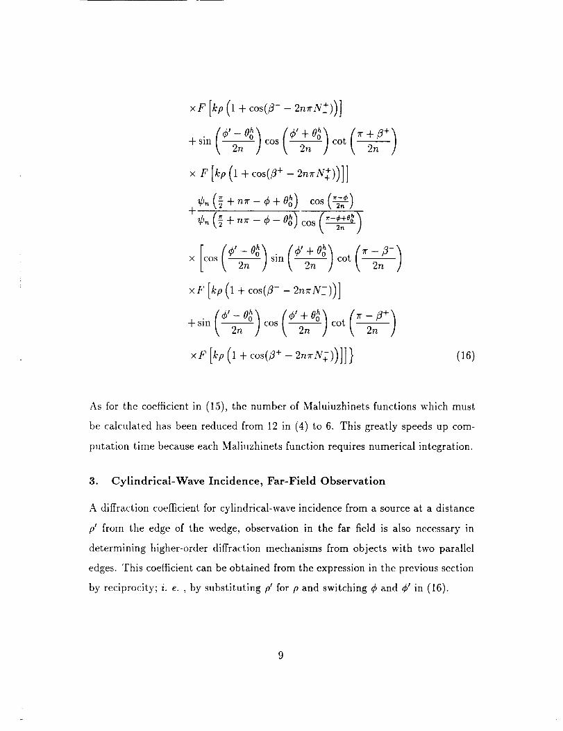
(16)
As for the coefficient in (15), the number of Maluiuzhinets functions which must
be calculated has been reduced from 12 in (4) to 6. This greatly speeds up com-
putation time because each Maliuzhinets function requires numerical integration.
3. Cylindrical-Wave Incidence, Far-Field Observation
A diffraction coet_cient for cylindrical-wave incidence from a source at a distance
p' from the edge of the wedge, observation in the far field is also necessary in
determining higher-order diffraction mechanisms from objects with two parallel
edges. This coefficient can be obtained from the expression in the previous section
by reciprocity; i. e., by substituting p' for p and switching 4>and q_' in (16).

4. Surface-Wave Terms
Surface-wavefields originate at the point of diffraction on an impedancewedge
and propagatealong the surfaceof the wedge.Although they decayrapidly along
the wedgeface,they canbe a major contribution to higher-orderdiffracting fields
and shouldbe consideredin any model of a complicatedgeometry. Surfacewaves
exist only overa limited angular regiongiven by:
(17)
where
c_0 = err0 + J_io = ¢ + _" + 0o (18)
The above expressions are for the "0" face of the wedge. For the coated wedge
considered in this work, the "n" face is perfectly conducting and cannot, therefore,
support surface waves.
The expression for the surface wave that exists on the "0" face of a general
impedance wedge is [14]:
sin/'/]71" 71"
¢,,(n_- - _)¢.(_ + r_,_+ 200)
3_r a-
×_"(T + Oo- o.)¢,,(_ + Oo+ o,,)
e-Jk° ¢os(¢+0o)
(19)
For the hard polarization case for the coated wedge this expression simplifies to:
10

,_ (.+oo'_ e-jkp ¢os(_,+0o)
u;% = -2Uo (_.-_,-o_ (__ (_+Oo-,'_cos _, 2,_ ) sin sink 2n ] \ 2n ]
_,_(_- - _);,.(_ + ,_._-+ 2Oo)_,.(,_-- _' - Oo)x 2 (20)
- +0o)
The above expression assumes plane-wave incidence and observation at a finite
distance, p. This term should be used to calculate only second-order diffractions
due to surface waves. A mathematically sound method for determining higher-
order diffractions due to surface waves using the UTD for impedance wedges has
not yet been found.
Since the surface wave terms exist over a finite angular range, a surface wave
transition boundary, at which a discontinuity occurs, exists. This is similar to
the incident and reflected ray boundaries in Geometrical Optics (GO). Just as the
UTD field corrects for GO discontinuities, the surface-wave transition field corrects
for discontinuities in the surface-wave field. The surface- wave transition field for
the "0" face of a general impedance wedge is [7]:
oUswtr
e -jk° [-_Z sin(_)] sin(£)
[F[kp(1- cos(_ + 0o))]- il
_/k(cos(4) + 0o) - 1)
_)_,,_(_ + ,_.-+ 200)
x,_( + Oo- o.)_(_ + Oo+ on) (21)
For the coated wedge, hard polarization case, this simplifies to:
11
sin(_) sin(_) cos( _ )
v/cos(_,+ Oo)- 1cos(""7,_-°°)
[F[kp(1 - cos(6 + 0o))1 _ 1]] tx sin(_) sin(_) J
_,,(r_"- _)_,,,(_+ _- + 20o)_,,,(_,,"-4/-- _"--0o)X
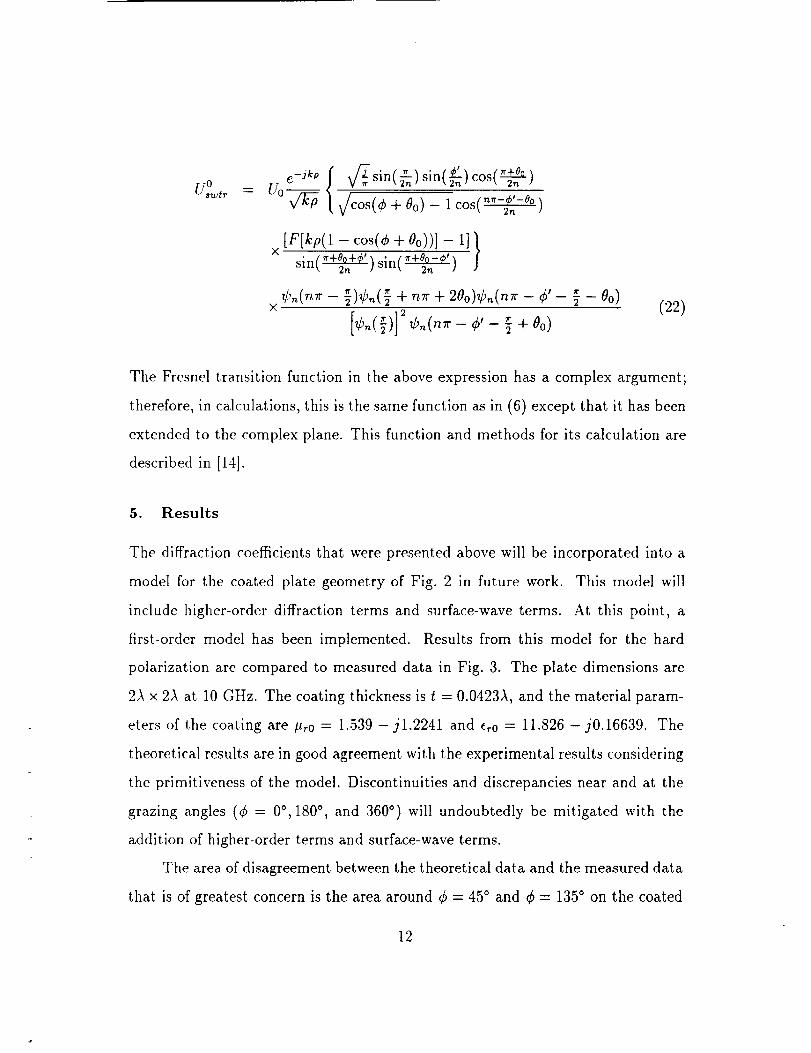
[ - Oo)_,, G(,,_ - -_+(22)
The Fresnel transition function in the above expression has a complex argument;
therefore, in calculations, this is the same function as in (6) except that it has been
extended to the complex plane. This function and methods for its calculation are
described in [14].
5. Results
The diffraction coefficients that were presented above will be incorporated into a
model for the coated plate geometry of Fig. 2 in future work. This model will
include higher-order diffraction terms and surface-wave terms. At this point, a
first-order model has been implemented. Results from this model for the hard
polarization are compared to measured data in Fig. 3. The plate dimensions are
2)_ x 2)_ at 10 GHz. The coating thickness is t = 0.0423A, and the material param-
eters of the coating are #r0 = 1.539 - jl.2241 and e_0 = 11.826 - j0.16639. The
theoretical results are in good agreement with the experimental results considering
the primitiveness of the model. Discontinuities and discrepancies near and at the
grazing angles (_b = 0°, 180 °, and 360 °) will undoubtedly be mitigated with the
addition of higher-order terms and surface-wave terms.
The area of disagreement between the theoretical data and the measured data
that is of greatest concern is the area around q_= 45 ° and _b= 135 ° on the coated
12

side of the plate. The disagreement in these areas is large, and it is not evident
that the addition of higher-order terms will resolve the differences. This is a critical
scattering angle in the modeling of the coated 90 ° dihedral corner reflector because
this angle corresponds to the angle of incidence with respect to the two plates
comprising the reflector when the backscattered field from the reflector is greatest.
Accurate modeling of the coated dihedral corner reflector depends, therefore, on
accurate modeling of the coated plate at ¢ = 45 ° and ¢ = 135 °. The equation
(1) for the coating impedance may not be a sufficient model at this angle because
this formulation is intended for use near and at normal incidence to the plate.
Higher-order boundary conditions may be necessary in modeling the coating for
angles away from normal incidence. This will be investigated in future work.
III. FUTURE WORK
Immediate future work will entail formulating a more sophisticated coated
plate model that includes higher-order diffractions and surface-wave terms. Terms
up to fourth order will be added. Work on the perfectly conducting, rectangular
plate has shown that terms of order higher than fourth order are very insignificant
contributors to the total scattered field [12].
The coated wedge coefficients and coated plate model will also be extended to
the soft polarization case. For this case the Brewster angle for the "n" face, given
in (3), is infinite. Formulating the coefficients for this case is not as straightforward
as for the hard polarization case. This problem is currently under investigation.
Although adding higher-order terms will probably improve the coated plate
to a certain degree, a higher-order boundary condition is obviously needed for
modeling the coating boundary conditions at angles away from normal incidence,
as was indicated by the results in Fig. 3. Several different approaches to developing
generalized impedance boundary conditions (GIBC's) have been presented in the
13

recent literature [16] - [18]. Thesemethods will be explored and applied to the
coatedplate geometry.
Just as for the perfectly conducting plate geometry,overlapping transition
regionsthat appearat and neargrazing incidenceare problemareasin which the
UTD cannot beapplied in its traditional form. This problem and its solution are
exploredby Tiberlo, et al. [19]. This solution will be incorporated into the general,
coated plate solution in the future.
Eventually, the work on coated geometries will be extended to more compli-
cated, general problems, specifically the coated dihedral corner reflector and the
rotated coated plate (i.e., scattering in off-principal planes). In the off-principal
plane case it will be necessary to explore hybrid methods such as the MM/PO
approach presented by Bilow [20]. This and other appropriate solutions will be
investigated in future work.
14
References
[1] J. B. Keller, "Geometrical theory of diffraction," J. Opt. Soc. Amer. , vol. 52,
pp. 116-130, Feb. 1962.
[2] R. G. Kouyoumjian and P. H. Pathak, "A uniform geometrical theory of
diffraction for an edge in a perfectly conducting surface," Proc. IEEE, vol. 62,
pp. 1448-1461, Nov. 1974.
[3] P. I. Ufimtsev, "Approximate computation of the diffraction of plane electro-
magnetic waves at certain metal bodies: I. Diffraction patterns at a wedge
and a ribbon," Sov. Phys. - Tech. Phys. , vol. 27, pp. 1708-1718, 1957.
[4] --, "Secondary diffraction of electromagnetic waves by a strip," Soy. Phys. -
Tech. Phys. , vol. 28. , pp. 535-548, 1958.
[5] G. D. Maluizhinets, "Excitation, reflection, and emission of surface waves
from a wedge with given face impedances," Soy. Phys. Doklady, vol. 3, pp.
752-755, Jul./Aug. 1958.
[6] R. Tiberio, G. Pelosi, and G. Manara, "A uniform GTD formulation for the
diffraction by a wedge with impedance faces," IEEE Trans. Antennas Propa-
gat. , vol. AP-33, pp. 867-873, Aug. 1985.
[7]T. Griesser and C. A. Balanis, "Reflections, diffractions, and surface waves
for an impedance wedge of arbitrary angle," IEEE Trans. Antennas
Propagat. , vol. AP-37, pp. 927-935, Jut. 1989.
[8] T. Griesser, C. A. Balanis, and K. Liu, "RCS analysis and reduction for lossy
dihedral corner reflectors," Proc. IEEE, vol. 77, pp. 806-814, May 1989.
[9] C. A. Balanis, L. A. Polka, and K. Liu, "Nonprincipal-plane scattering from
rectangular plates and pattern control of horn antennas," Semiannual Report,
Grant No. NAG-I-562, National Aeronautics and Space Administration, Lan-
gley Research Center, Hampton, VA, Jan. 31, 1990.
[10] --, "Scattering from coated structures and antenna pattern control using
impedance surfaces," Semiannual Report, Grant No. NAG-I-562, National
Aeronautics and Space Administration, Langley Research Center, Hampton,
VA, Jul. 31, 1990.
15

[11]
[12]
[13]
[14]
C. A. Balanis and L. A. Polka, "High-frequency techniques for RCS prediction
of plate geometries," Semiannual Report, Grant No. NAG-I-562, National
Aeronautics and Space Administration, Langley Research Center, Hampton,
VA, Jan. 31, 1991.
--, "tIigh-frequency techniques for RCS prediction of plate geometries," Semi-
annual Report, Grant No. NAG-I-562, National Aeronautics and Space Ad-
ministration, Langley Research Center, Hampton, VA, Jul. 31, 1991.
--, "High-frequency techniques for RCS prediction of plate geometries," Semi-
annual Report, Grant No. NAG-I-562, National Aeronautics and Space Ad-
ministration, Langley Research Center, Hampton, VA, Jan. 31, 1992.
T. Griesser, "High-frequency electromagnetic scattering from imperfectly con-
ducting structures," Ph.D. dissertation, Arizona State University, Tempe,
Arizona, Aug. 1988.
[15] M. I. Herman, J. L. Volakis, and T. B. A. Senior, "Analytic expressions for a
function occurring in diffraction theory," IEEE Trans. Antennas Propagat. ,
vol. AP-35, 1083-1086, Sept. 1987.
[16] R. G. Rojas, "Generalised impedance boundary conditions for EM scattering
problems," Electronic Letters, vol. 24, pp. 1093-1094, Aug. 18, 1988.
[17]
[18]
[19]
[2o]
R. G. Rojas and Z. A1-Hekail, "Generalized impedance/resistive boundary
conditions for electromagnetic scattering problems," Radio Science, vol. 24,
pp. 1-12, Jan. /Feb. 1989.
J. -M. L. Bernard, "Diffraction by a metallic wedge covered with a dielectric
material," Wave Motion, vol. 9, pp. 543-561, Nov. 1987.
R. Tiberio, R. Bessi, G. Manara, and G. Pelosi, "Scattering by a strip with two
face impedances at edge-on incidence," Radio Science, vol. 17, pp. 1199-1210,
Sept. / Oct. 1982.
H. J. Bilow, "Scattering by an infinite wedge with tensor impedance boundary
conditions - a moment method/physical optics solution for the currents,"
IEEE Trans. Antennas Propagat. , voI. 39, pp. 767-773, Jun. 1991.
16

Plane-waveInc idence
Far-fieldObservation
(2-n)_
face"n"
Fig. 1. Impedance wedge geometry.
17

Plane-wave
Incidence
_- I i I
Fig. 2. Geometry for principal-plane scattering from astrip/plate
with a finite-thickness coating backed by a perfect conductor.
18

0
/
0
00
0
%
0
0
0
0
_9


![[Rcs Iot] Rcs-e v1-2- Joyn](https://img.pdfslide.net/doc/110x75/577cd0231a28ab9e78917fbc/rcs-iot-rcs-e-v1-2-joyn.jpg)
