Embed Size (px)
Citation preview

Dr. Eng. Ashraf I. M.
El-Sabbagh
Dr. Eng. Ashraf I. M.
El-Sabbagh
DESIGN OF STEEL STRUCTURES (1)
CIE402
DESIGN OF STEEL STRUCTURES (1)
CIE402
High Institute for Engineering & Technology - New Damietta
Civil Engineering Department
2014-20152014-2015

Des
ign
of S
teel
Str
uctu
res
– CI
E402
4th
Lev
el -
CIVI
L
2
LAYOUT OF STEEL STRUCTURES
2.1 Structural Systems
Structures can be classified into two main
categories with respect to the way that the
loads act on the structure as well as the
simplicity of structural analysis:
1- Plane structures.
2- Space structures.

Des
ign
of S
teel
Str
uctu
res
– CI
E402
4th
Lev
el -
CIVI
L
3
LAYOUT OF STEEL STRUCTURES
2.1 Structural Systems
The steel structures can be classified according to
type of members and their connections in to
three categories:
1- Truss structures.
2- Frame structures.
3- Combined truss and frame structures.

Des
ign
of S
teel
Str
uctu
res
– CI
E402
4th
Lev
el -
CIVI
L
4
LAYOUT OF STEEL STRUCTURES
2.1 Structural Systems
a – Plane truss
Des
ign
of S
teel
Str
uctu
res
– CI
E402
4th
Lev
el -
CIVI
L
5
LAYOUT OF STEEL STRUCTURES
2.1 Structural Systems
b- Single story plane frame

Des
ign
of S
teel
Str
uctu
res
– CI
E402
4th
Lev
el -
CIVI
L
6
LAYOUT OF STEEL STRUCTURES
2.1 Structural Systems
c – Multistory plane frame

Des
ign
of S
teel
Str
uctu
res
– CI
E402
4th
Lev
el -
CIVI
L
7
LAYOUT OF STEEL STRUCTURES
2.1 Structural Systems
d- Multistory space frame

Des
ign
of S
teel
Str
uctu
res
– CI
E402
4th
Lev
el -
CIVI
L
8
LAYOUT OF STEEL STRUCTURES
2.1 Structural Systems
e – Space truss, industrial building
Des
ign
of S
teel
Str
uctu
res
– CI
E402
4th
Lev
el -
CIVI
L
9
LAYOUT OF STEEL STRUCTURES
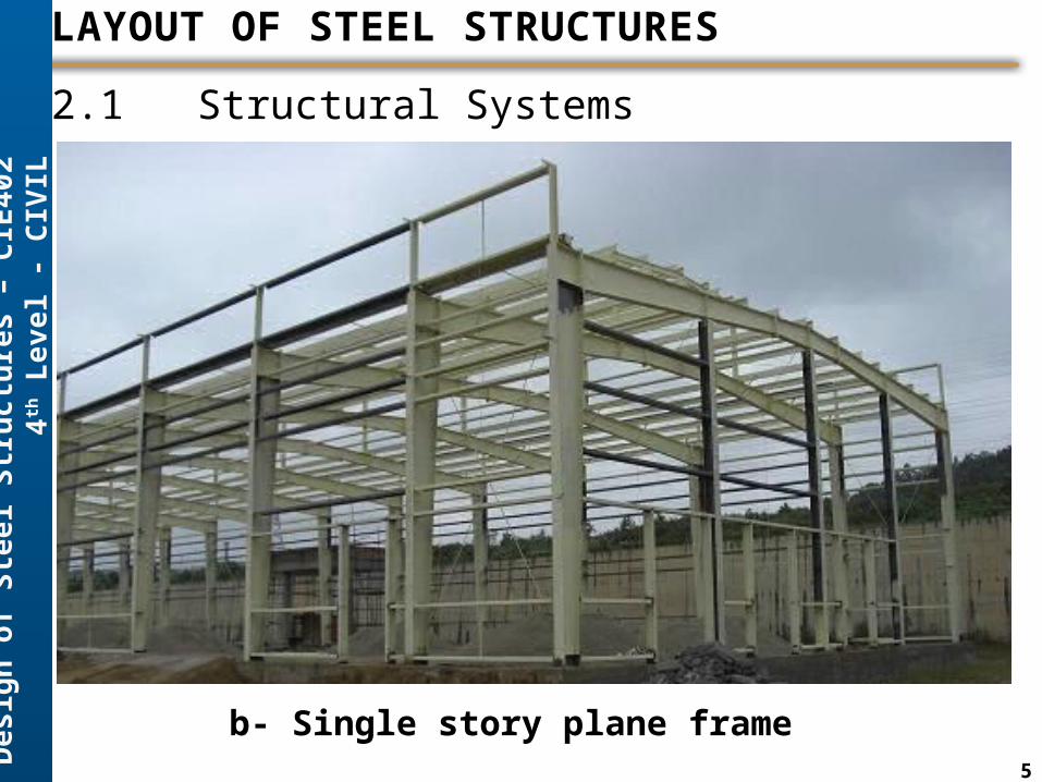
2.1 Structural Systems
f- Space truss, stadium shed

Des
ign
of S
teel
Str
uctu
res
– CI
E402
4th
Lev
el -
CIVI
L
10
LAYOUT OF STEEL STRUCTURES
2.1 Structural Systems
We shall concentrate on the design of plane trusses and frames
because they are frequently used in steel structures in Egypt.
Plane structures have the following advantages:
1-Simple structural system leads to easier structural analysis.
2-Easy and fast fabrication in workshop.
3-Simple connections and fast construction.
4-Structure can be extended in future without any complications.

Des
ign
of S
teel
Str
uctu
res
– CI
E402
4th
Lev
el -
CIVI
L
11
LAYOUT OF STEEL STRUCTURES
2.2 Parts of Plane Steel Building
The structure is mainly composed of four main
elements:
1- Main (primary) framing system.
2- Secondary members.
3- Wind bracing system.
4- Cladding.

Des
ign
of S
teel
Str
uctu
res
– CI
E402
4th
Lev
el -
CIVI
L
12
LAYOUT OF STEEL STRUCTURES
2.2 Parts of Plane Steel Building

Des
ign
of S
teel
Str
uctu
res
– CI
E402
4th
Lev
el -
CIVI
L
13
LAYOUT OF STEEL STRUCTURES
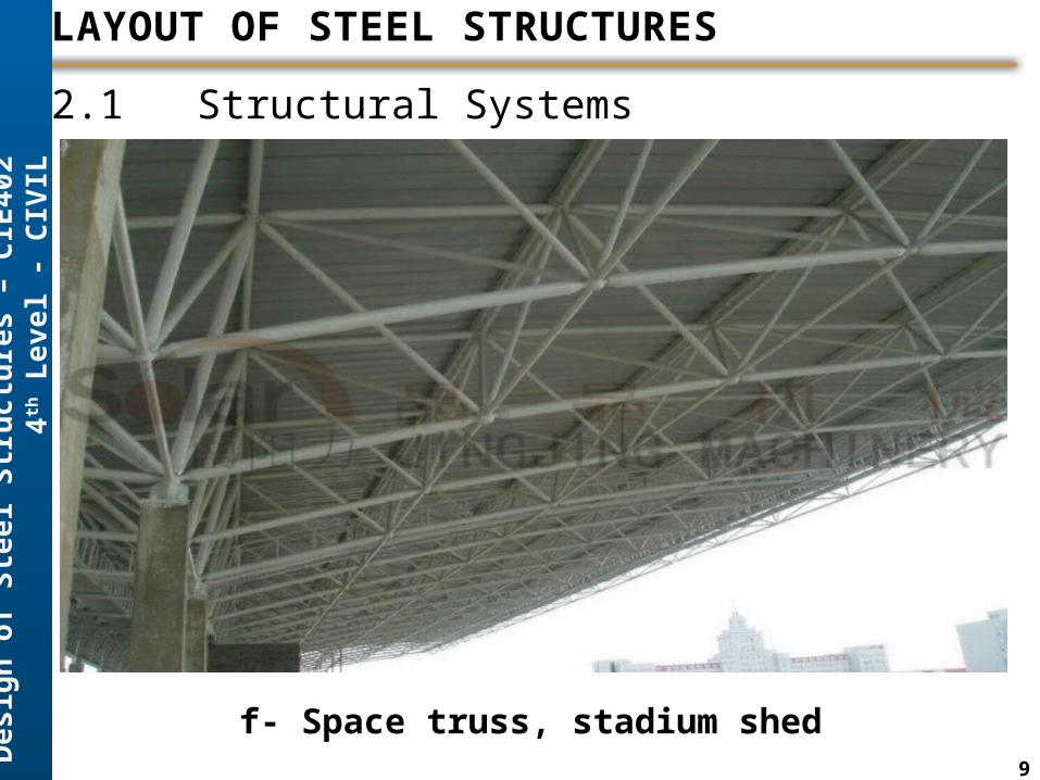
2.2 Parts of Plane Steel Building - Cladding
The construction of the external skin of a building can
take several forms, the most prevalent being:
(1) Single-skin trapezoidal shell
(2) Double-skin trapezoidal shell
(3) Standing seam with concealed fixings
(4) Composite panels.
Des
ign
of S
teel
Str
uctu
res
– CI
E402
4th
Lev
el -
CIVI
L
14
LAYOUT OF STEEL STRUCTURES
2.2 Parts of Plane Steel Building - Cladding

Des
ign
of S
teel
Str
uctu
res
– CI
E402
4th
Lev
el -
CIVI
L
15
LAYOUT OF STEEL STRUCTURES
2.2 Parts of Plane Steel Building – Secondary Elements
Secondary members are mainly:
• Purlins which carry roof cladding.
• Side-girts and end-wall-girts which carry wall cladding.
A combination of cladding performance, erect-ability
and the restraint requirements for economically-
designed main frames dictates that the purlin and rail
spacing should be 1.5–2m.

Des
ign
of S
teel
Str
uctu
res
– CI
E402
4th
Lev
el -
CIVI
L
16
LAYOUT OF STEEL STRUCTURES
2.2 Parts of Plane Steel Building – Secondary Elements
SIB IPE Channel
Cold Formed Channel
Cold Formed Z
Cold Formed Lipped Channel
Cold Formed Lipped Z
Stiffened Unstiffened

Des
ign
of S
teel
Str
uctu
res
– CI
E402
4th
Lev
el -
CIVI
L
17
LAYOUT OF STEEL STRUCTURES
2.3 Main Framing Systems
Trusses for Building Roof

Des
ign
of S
teel
Str
uctu
res
– CI
E402
4th
Lev
el -
CIVI
L
18
LAYOUT OF STEEL STRUCTURES
2.3 Main Framing Systems

Des
ign
of S
teel
Str
uctu
res
– CI
E402
4th
Lev
el -
CIVI
L
19
LAYOUT OF STEEL STRUCTURES
2.3 Main Framing Systems

Des
ign
of S
teel
Str
uctu
res
– CI
E402
4th
Lev
el -
CIVI
L
20
LAYOUT OF STEEL STRUCTURES
2.3 Main Framing Systems

Des
ign
of S
teel
Str
uctu
res
– CI
E402
4th
Lev
el -
CIVI
L
21
LAYOUT OF STEEL STRUCTURES
2.3 Main Framing Systems
Pratt (N) Truss with Non-Parallel Chords
Span (L ≤ 34 m)
h
a
H
1k
h
a
Pratt (N) Truss with Parallel Chords
Des
ign
of S
teel
Str
uctu
res
– CI
E402
4th
Lev
el -
CIVI
L
22
LAYOUT OF STEEL STRUCTURES
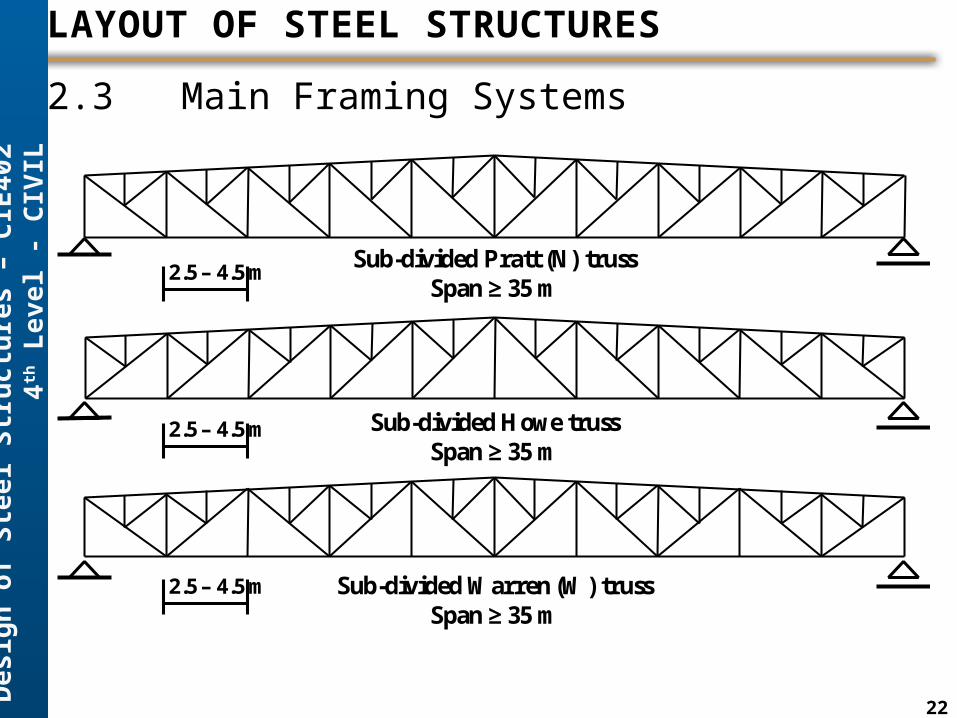
2.3 Main Framing Systems
Sub-divided Pratt (N) trussSpan ≥ 35 m
Sub-divided Howe trussSpan ≥ 35 m
Sub-divided Warren (W) trussSpan ≥ 35 m
2.5 – 4.5 m
2.5 – 4.5 m
2.5 – 4.5 m

Des
ign
of S
teel
Str
uctu
res
– CI
E402
4th
Lev
el -
CIVI
L
23
LAYOUT OF STEEL STRUCTURES
2.3 Main Framing Systems
Non-Parallel Chords
Parallel Chords
Trusses for Building Roof
Span (L = n x a)
h
a
H
1k
h
a

Des
ign
of S
teel
Str
uctu
res
– CI
E402
4th
Lev
el -
CIVI
L
24
LAYOUT OF STEEL STRUCTURES
2.3 Main Framing Systems
The spacing: of the main system frames is normally in the range: S= 5 8m, with 6.0 m and
7.5 m as the most common spacings.
Panel length, a = 1.5 2.5 m, anL , number of panels (n) must be even number (10, 12,
14, …),. To satisfy the angle of web members ( 5535a ) the panel length shall satisfy
Hah . If a>2.5 m use subdivided truss.
Slope of upper chord of truss, 5:1 20:1, but 10:1 is commonly used (Slope k:1).
Non-Parallel Chords
Parallel Chords
Trusses for Building Roof
Span (L = n x a)
h
a
H
1k
h
a

Des
ign
of S
teel
Str
uctu
res
– CI
E402
4th
Lev
el -
CIVI
L
25
LAYOUT OF STEEL STRUCTURES
2.3 Main Framing Systems
Depth of main truss, 1610
L
H , where, L =span of main truss.
,25.11
2 min mhk
LHh otherwise, increase the depth (H).
Or simply take mhah 25.1min
Non-Parallel Chords
Parallel Chords
Trusses for Building Roof
Span (L = n x a)
h
aH
1k
h
a

Des
ign
of S
teel
Str
uctu
res
– CI
E402
4th
Lev
el -
CIVI
L
26
LAYOUT OF STEEL STRUCTURES
2.4 Wind Bracing Systems
The main functions of bracing systems are:
1- Resist and horizontal forces in the out-of-plane
direction of the main system (long direction of the
building).
2- Hold the structure during construction.
3- Reduce buckling length of upper chord out-of-plane.
4- Brace the whole structure in the long direction.

Des
ign
of S
teel
Str
uctu
res
– CI
E402
4th
Lev
el -
CIVI
L
27
LAYOUT OF STEEL STRUCTURES
2.4 Wind Bracing Systems
Bracing system must be made in the first and last panels
with spacing between 25 – 30 m in the long direction.
Horizontal bracing works as a horizontal truss to
withstand wind forces and transmit them to the
vertical bracing which in turn transmits them to
foundation.

Des
ign
of S
teel
Str
uctu
res
– CI
E402
4th
Lev
el -
CIVI
L
28
LAYOUT OF STEEL STRUCTURES
2.5 End Gable
It is the system that carries the walls, windows, and
doors at the end sections of the building.
It consists of: end gable columns that carry the end
gable girts (beams) that are carry the cladding,
windows, and doors.

Des
ign
of S
teel
Str
uctu
res
– CI
E402
4th
Lev
el -
CIVI
L
29
LAYOUT OF STEEL STRUCTURES
2.5 End Gable
• The spacing between columns is
commonly between (4.0 – 8.0 m).
• The vertical spacing between girts (1.5 – 2.0 m).
• Window height is taken (1.0 – 1.5 m).
• Brick wall height (2.0 – 4.0 m) with minimum
thickness (25 cm).
• They are most of the common forms provide
resistance to sidesway forces such as wind loads
Des
ign
of S
teel
Str
uctu
res
– CI
E402
4th
Lev
el -
CIVI
L
30
LAYOUT OF STEEL STRUCTURES
2.6 Structural Layout
Structural layout is the drawing that shows the main
dimensions and components of the structure.
The typical scale of steel layout drawing is usually 1:100
or 1:200 for large areas.
The main components that must be shown after
removing of all cladding:

Des
ign
of S
teel
Str
uctu
res
– CI
E402
4th
Lev
el -
CIVI
L
31
LAYOUT OF STEEL STRUCTURES
2.6 Structural Layout
The main components that must be shown after
removing of all cladding:
1- Plan view
2- Elevation view
3- Side view.
4- End gable side view.
5- Intermediate vertical bracing (truss system).

Des
ign
of S
teel
Str
uctu
res
– CI
E402
4th
Lev
el -
CIVI
L
32
LAYOUT OF STEEL STRUCTURES
2.6 Structural Layout

Des
ign
of S
teel
Str
uctu
res
– CI
E402
4th
Lev
el -
CIVI
L
33
LAYOUT OF STEEL STRUCTURES
2.6 Structural Layout

Des
ign
of S
teel
Str
uctu
res
– CI
E402
4th
Lev
el -
CIVI
L
34
LAYOUT OF STEEL STRUCTURES
2.6 Structural Layout

Des
ign
of S
teel
Str
uctu
res
– CI
E402
4th
Lev
el -
CIVI
L
35
LAYOUT OF STEEL STRUCTURES
2.6 Structural Layout

Des
ign
of S
teel
Str
uctu
res
– CI
E402
4th
Lev
el -
CIVI
L
36
LAYOUT OF STEEL STRUCTURES
2.6 Structural Layout

Des
ign
of S
teel
Str
uctu
res
– CI
E402
4th
Lev
el -
CIVI
L
37
LAYOUT OF STEEL STRUCTURES
2.6 Structural Layout

Des
ign
of S
teel
Str
uctu
res
– CI
E402
4th
Lev
el -
CIVI
L
38
LAYOUT OF STEEL STRUCTURES
2.6 Structural Layout

Des
ign
of S
teel
Str
uctu
res
– CI
E402
4th
Lev
el -
CIVI
L
39
LAYOUT OF STEEL STRUCTURES
2.6 Structural Layout