Embed Size (px)
Citation preview
Future Renewable Electric Energy Delivery and Management Systems Center
1
Subhashish Bhattacharya
Dept. of ECE, FREEDM Systems Center
NC State University
High MegaWatt MV Drives

Future Renewable Electric Energy Delivery and Management Systems Center
MV drives issues and needs
• 60-70% of the MV motors are not driven by drives – why? • Estimate yearly energy savings • Capital cost requirement – payback period • Space important ? – match footprint of soft-starter ? • MV motors are used typically in critical processes – steel
mills, cement kilns, air-handling, compressors, pumps • Reliability is key; downtime is allowed with concept of
“modular replacement” possible by semi-skilled people
• MV Motor energy efficiency – what does higher NEMA energy efficiency standards mean – lower losses -> lower damping – need for higher current bandwidth control required? • Can SiC play a real role? Enable high speed motor
designs (future)

Future Renewable Electric Energy Delivery and Management Systems Center
500 kW Si-IGBT based drive
For 4.16 kV, 500 kW system, line rms current = 69A, peak current of each
phase = 98 A. Peak of line to line voltage is 5.88kV. Hence, two 6.5kV/200A
Silicon IGBT devices are required to be in series to block forward voltage.
However, Si-IGBTs cannot be switched at high frequency while conducting high
current. Hence, around 4 interleaved inverters are required to switch at around
1.5 kHz. Each inverter block is switched at 300-400Hz.

Future Renewable Electric Energy Delivery and Management Systems Center
500 kW SiC Mosfet based drive
For the same 4.16 kV, 500 kW drive system, using 10 kV/120A SiC-
Mosfet, it is possible to have a 2-level topology. The SiC devices can
be switched at 5 kHz, for 69A rms (98A peak) current, and a single
device can withstand the forward blocking voltage of Vdc = 6kV.
SiC MOSFET kV rating? 10kV, 12kV, 15kV

Future Renewable Electric Energy Delivery and Management Systems Center
500 kW SiC Mosfet based drive
SiC MOSFET kV rating? 10kV, 12kV, 15kV
• Rds(on) vs Vdc, Temp. upto 125-150 deg C
• J (A/cm2), die size -> packaging issues, thermal, overload current
rating, device short circuit protection and time, inductance, non-wire
bond packaging (for thermal, not only fail-short), maximum module
current rating
• SiC device designed for short-circuit capability – what does this
mean for Vce(sat), Eon and Eoff, positive temp. coeff.
• Characterization of switching frequency vs. thermal, Voltage
• Eon and Eoff vs. I, V and temp. [function of V important]
• Dv/dt and its management – active gate driving, ZVS (?)

Future Renewable Electric Energy Delivery and Management Systems Center
50 kW SiC-Mosfet based Inverter
50 kW drive system, using 1200 V/100A SiC-Mosfet.
The SiC devices can be switched at 20-40 kHz, Vdc = 800V.

Future Renewable Electric Energy Delivery and Management Systems Center
Gen-I SST : Topology and Prototype
Specifications: • Input: 7.2kV
• Output: 240Vac/120Vac; 400Vdc
• Power rating: 20kVA
+
-
+
-
3.8kV
DC
+
-
+
-
400V
DC
3.8kV
DC
SH5
SH7
SH6
SH8
S1
S3S4
SH1
SH3SH4
SH2 S2
Low Voltage
H-Bridge
+
-
+
-
400V
DC
High Frequency
Transformer
AC/DC Rectifier DC/DC Converter DC/AC Inverter
High Voltage
H-BridgeHigh voltage
H-Bridge
3.8kV
DC
7.2 kV AC
120V /
240V AC
LLs
Cs
CsLs
Port 1
Port 2
400V DC
+
-
Port 3
Rectifier Stage DAB Secondary DAB Primary
Inverter
Named to MIT Technology Review's 2011 list of the world's 10 most important emerging technologies

Future Renewable Electric Energy Delivery and Management Systems Center
8
FREEDM SST: Two generations (Si vs SiC)
Pole mounted
transformer
Gen-II SST 15kV SiC MOSFET based
Gen-I SST 6.5kV Si IGBT based
Input: 7.2kVac Output: 240Vac/120Vac; 380Vdc Power rating: 20kVA
+
-
+
-
+
-
+
-
L
DC/AC Inverter
Ls
Cs
Cs
Ls
Dual Half Bridge Rectifier

Future Renewable Electric Energy Delivery and Management Systems Center
Solid State Transformer (SST) –
MV drives relationship
Three stage SST • AC to DC converter,
• DC to DC converter with high frequency transformer
• DC to AC converter
Features: • Active/Reactive power control at both HV and LV side grids
• Integration of both AC and DC renewable energy sources
• High frequency isolation – most MV drives are 1:1 in terms of voltage input/output
• SiC devices are key enabler for DC-DC transformer 9

Future Renewable Electric Energy Delivery and Management Systems Center
Transformerless Intelligent Power
Substation (TIPS) – 3 phase SST
10

Future Renewable Electric Energy Delivery and Management Systems Center
11
15 kV, 20 A SiC IGBT Co-pack Modules
The module includes: - 15 kV, 20 A SiC IGBT - 20 kV (10*2), 10 A SiC JBS Diodes - Current sense resistors - Thermistor
20A N-IGBT
15A JBS Diode
Collector
AlN
Emitter
CurrentSense
Resistors
RTD

Future Renewable Electric Energy Delivery and Management Systems Center
Turn-off transition at 11 kV, 5 A, 25oC
VGE (20 V/div); VCE (2 kV/div);
IC (5 A/div); EOFF (15 mJ/div);
Time scale: 1000 ns/div
Characteristics of 15 kV, 20 A, SiC IGBT
12
• RG(OFF) = 10 Ω.
• Voltage has two different
slopes. (punch-through
design)
• Current bump; tail ringing.
• Total duration of the
transition = 650 ns.
• Energy loss = 17.6 mJ
Future Renewable Electric Energy Delivery and Management Systems Center
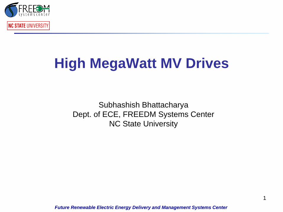
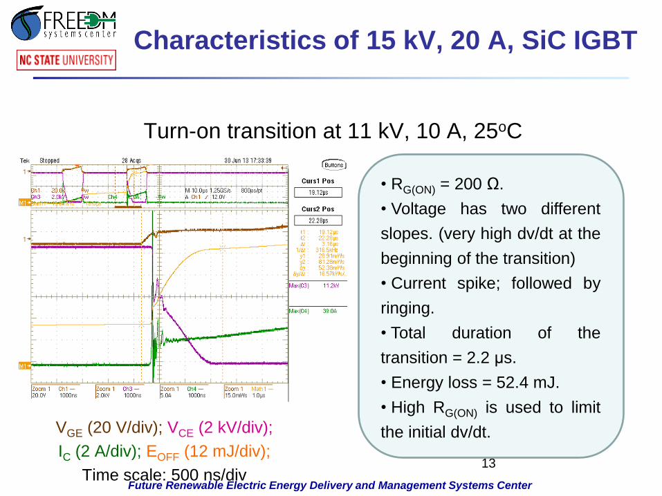
Turn-on transition at 11 kV, 10 A, 25oC
VGE (20 V/div); VCE (2 kV/div);
IC (2 A/div); EOFF (12 mJ/div);
Time scale: 500 ns/div
Characteristics of 15 kV, 20 A, SiC IGBT
13
• RG(ON) = 200 Ω.
• Voltage has two different
slopes. (very high dv/dt at the
beginning of the transition)
• Current spike; followed by
ringing.
• Total duration of the
transition = 2.2 μs.
• Energy loss = 52.4 mJ.
• High RG(ON) is used to limit
the initial dv/dt.

Future Renewable Electric Energy Delivery and Management Systems Center
14
HV Gate Driver
High Isolation Gate Driver 11 kV, high dv/dt switching
voltage of the IGBT
The Gate driver has been exposed to 100 kV/µs at 11 kV
Device maximum Turn ON and Turn OFF dv/dt
• Turn ON dv/dt = 100.6 kV/µs, Turn OFF dv/dt = 28.29 kV/µs

Future Renewable Electric Energy Delivery and Management Systems Center
Gate Driver Isolation Transformer
15
• Isolation transformer inter-winding coupling capacitance (a crucial
element for high dv/dt immunity) w.r.t frequency.
• Measured up to 110 MHz using Agilent Impedance Analyzer.
• 3.4 pF at 50 MHz; 13 pF at 100 MHz.

Future Renewable Electric Energy Delivery and Management Systems Center
10kV SiC MOSFET
Single 10kV SiC MOSFET Module

Future Renewable Electric Energy Delivery and Management Systems Center
VGE (10 V/div); VCE (2 kV/div);
IC (5 A/div); Time scale: 1000 ns/div
10 kV, 10 A SiC MOSFET Characteristics at Vdc = 6kV
10 kV/10 A SiC MOSFET switching
characteristics
17

Future Renewable Electric Energy Delivery and Management Systems Center
10kV SiC MOSFET based Inverter
2-level 3-phase Inverter built using 10kV SiC MOSFET
10kV
MOSFET

Future Renewable Electric Energy Delivery and Management Systems Center
TIPS DAB DC-DC Converter
POWER SCHEMATIC OF Y : Y /∆ THREE-PHASE DAB
Three HF single phase transformer
Cancellation of 3rd, 5th and 7th Harmonics
Predominantly sinusoidal current and flux
Lower Step Voltage on MV winding
Circuit Diagram Three-phase Y:Y/∆ DAB
19

Future Renewable Electric Energy Delivery and Management Systems Center
HV 3-phase DAB DC-DC Converter
20 Back view of the DAB converter The front view of the DAB converter
Future Renewable Electric Energy Delivery and Management Systems Center
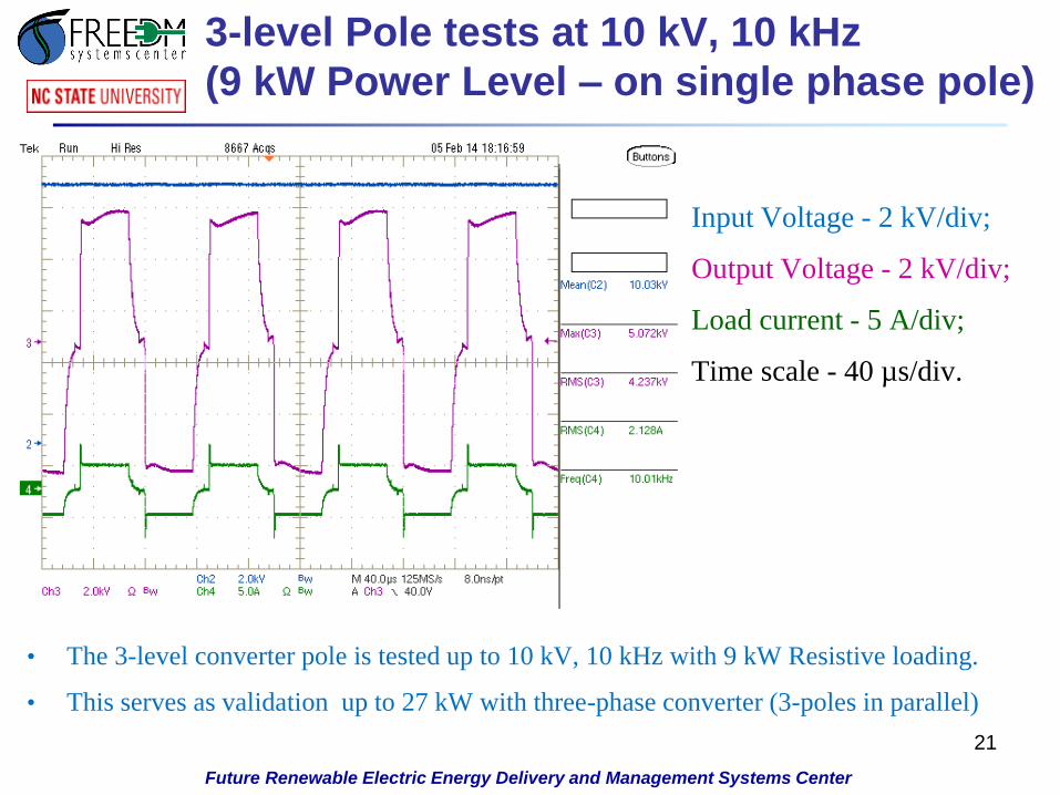
3-level Pole tests at 10 kV, 10 kHz
(9 kW Power Level – on single phase pole)
21
Input Voltage - 2 kV/div;
Output Voltage - 2 kV/div;
Load current - 5 A/div;
Time scale - 40 µs/div.
• The 3-level converter pole is tested up to 10 kV, 10 kHz with 9 kW Resistive loading.
• This serves as validation up to 27 kW with three-phase converter (3-poles in parallel)

Future Renewable Electric Energy Delivery and Management Systems Center
High Frequency Transformer for DAB
22/11 kV : 800V, 10 kHz, 35 kVA 1-Φ Transformer
P Y1
Y2
D1 D2
Transformer Connections
Pr
Py Pb
Yr
Yb Yy
Dr Db
Dy
• Insulation tested up to 22kV
• Oil filled transformer
• Three 1-Φ transformers are
connected in Y/Y-Δ for 3-Φ
DAB
22
Future Renewable Electric Energy Delivery and Management Systems Center
23
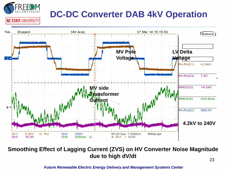
DC-DC Converter DAB 4kV Operation
Smoothing Effect of Lagging Current (ZVS) on HV Converter Noise Magnitude
due to high dV/dt
3kV to 217V
Partial ZVS?
4.2kV to 240V
LV Delta
Voltage
MV Pole
Voltage
MV side
Transformer
Current

24
FACTS
Convertible Static Compensator (CSC) - Marcy Substation FACTS Applications
Marcy 345kV
SC is 18,000
MVA
There are 11
possible
configurations
• STATCOM
• SSSC
• UPFC
• IPFC
TR - SH
200 MVA
INVERTER 1
100 MVADC Bus 1 DC Bus 2
SWDC
TBS1
LVCB
HSB
HSB
INVERTER 2
100 MVA
Marcy 345 kV
North Bus
Marcy 345 kV
South Bus
Edic
Volney AT1 AT2
TBS2
LVCB
TR - SE1
100 MVA
TR - SE2
100 MVA
New
Scotland
(UNS)
Coopers
Corners
(UCC)
HVCB
25
FACTS
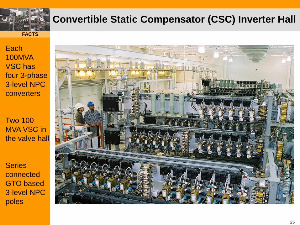
Convertible Static Compensator (CSC) Inverter Hall
Each
100MVA
VSC has
four 3-phase
3-level NPC
converters
Two 100
MVA VSC in
the valve hall
Series
connected
GTO based
3-level NPC
poles

26
FACTS
Main Components of 3-Level NPC Inverter Pole
-V
Three-level poleoutput waveform
+V
0
Series
connected
GTO based
3-level NPC
poles

27
FACTS
IGCT based 3-level NPC inverter pole
IGCT pole A1 IGCT pole A2
3 series IGCTs per valve

28
FACTS
H-bridge test - IGCT based 3-level NPC poles
IGCT pole A1 (top)
IGCT pole A2 (bottom)

Future Renewable Electric Energy Delivery and Management Systems Center
29
Subhashish Bhattacharya
Dept. of ECE, FREEDM Systems Center
NC State University
High MegaWatt MV Drives
Acknowledgements:
FREEDM Systems Center
ARPA-E and DOE
Dept. of ECE, NC State University