Embed Size (px)
Citation preview

High Nickel Alloys Offering a Combination of
High Strength and High Impact Properties
Chaman Lall & Eric Starr*
Metal Powder Products Company
16855 Southpark Drive, Suite 100, Westfield, IN 46074, USA.
* 310 Tanner Street, Ridgway, PA 15853, USA.
ABSTRACT
High nickel steels offer the opportunity to produce powder metallurgy components with excellent high
strength and ductility combinations. These alloys are a sinter-hardenable class of materials that do not
require conventional heat treatment processes to develop these unique properties. The alloys must be
sintered at high temperatures in order to obtain the value of the elemental additives that are included in
these ferrous alloys - as well as the enhancement of the densification process. As-sintered properties
include UTS values near 1380 MPa (200 ksi), yield strengths over 827 MPa (120 ksi) and elongations
over 2%. In addition, impact energy values are over 40 J (30 ft. lbf.). A post-sinter temper/draw cycle did
not further improve mechanical properties of the PM steels with higher Ni contents, and was deemed
unnecessary. When component failure due to insufficient ductility is not an option, these materials can
readily justify the slightly higher cost.
INTRODUCTION
The powder metallurgy (PM) process is an extremely flexible method of component manufacturing that
can result in highly ductile (>30% elongation) or very strong (>1500 MPa UTS) products. This wide
range of properties is possible because of the relative ease with which compositional changes can be made
and the many possible process parameters that can be controlled (compaction pressures, sintering time
and temperatures, post-sinter operations, heat treatment, surface modifications, etc.). In support of these
objectives to fulfill the wide-ranging needs of customers, powder producers have developed highly
engineered powders that offer great consistency in powder purity, morphology, and particle size
distribution. Further enhanced value is delivered to PM component makers with alloyed, partially alloyed,
and bonded powder combinations.

In the specific case of ferrous powder metallurgy, the degree of hardening or strengthening imparted by
addition of some selected metals is shown 1,2
in Figure 1. Perhaps the most important of these metals is
Mo, since a relatively small amount is needed to create significant hardenability. The element is not
detrimental to the compressibility of the base Fe during molding3 and, furthermore, is a ferrite stabilizer,
which enhances the sintering process due to the higher diffusion rates in the more open b.c.c. structure.
For more than two decades, the PM industry has utilized Mo because of its ability to harden iron, and is
the basis of many pre-alloyed powders intended for high strength structural parts.
Figure 1. Hardenability factors for selected pre-alloyed elements in Fe.1 Mo* is the
hardenability factor of the element for Ni contents>0.75 wt.%.
McQuaig and Sokolowski4 confirmed that low levels (0.3% to 0.5%) of pre-alloyed Mo are sufficient to
cause hardenability in parts with thin cross sections, but greater levels (0.85% or higher) are needed for
large cross-section parts. Furthermore, they also showed that admixed Ni was better for end-product
mechanical properties than pre-alloyed Ni, because the latter route decreased compressibility at the
molding stage. A study of dynamic properties5 concluded that increasing levels of Mo, improved fatigue
strength, but beyond 0.85 %Mo, no additional benefit was gained. The improved fatigue properties from
of 0.5 % to 0.85 %Mo were thought to be due to the change in microstructure from a divorced
pearlite/pearlite type to a bainite/martensite type. Again, affirming the role of Mo in enhancing
hardenability of the steel, as the level of this alloying element is increased.
Additional strengthening is achieved by alloying with Cu, Si, Cr, Mn and Ni, as shown in Figure 1. Mn,
however, has the disadvantage of decreasing compressibility3 and, to make matters worse, has a high
affinity for oxygen.6 Along with Mn, the stable oxides of Cr and Si are more difficult to reduce (Figure 2)
in conventional sintering temperatures and atmospheres.2, 6-9
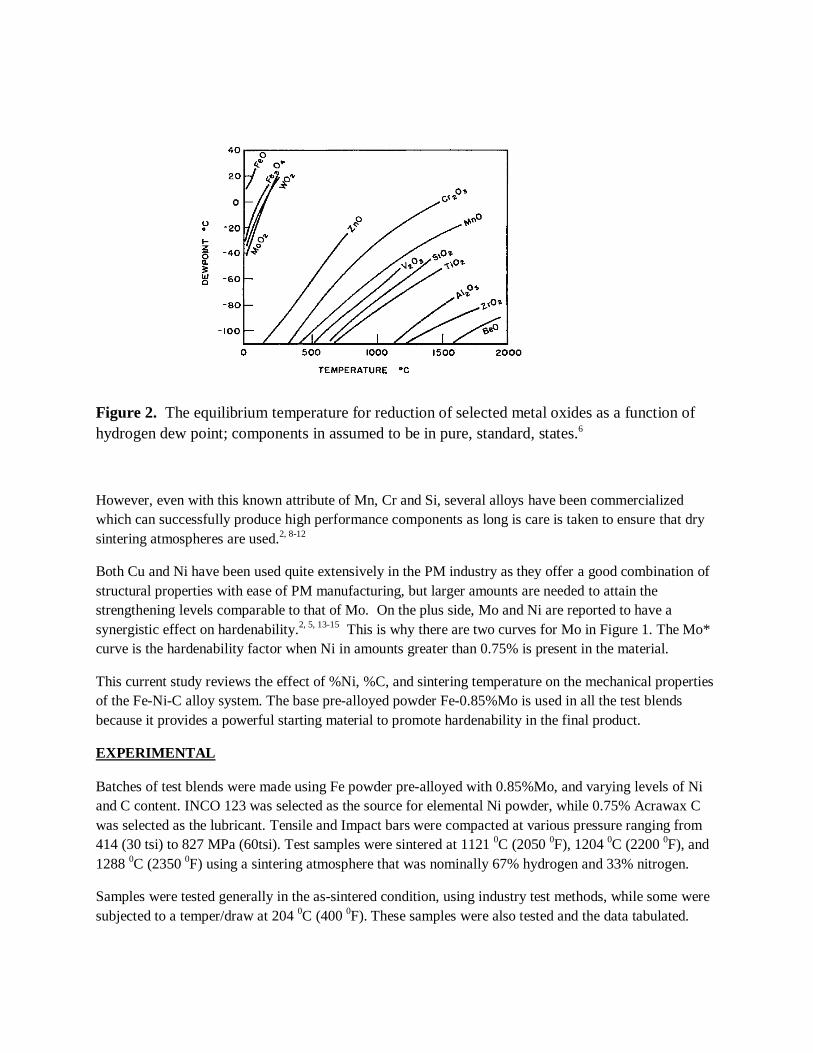
Figure 2. The equilibrium temperature for reduction of selected metal oxides as a function of
hydrogen dew point; components in assumed to be in pure, standard, states.6
However, even with this known attribute of Mn, Cr and Si, several alloys have been commercialized
which can successfully produce high performance components as long is care is taken to ensure that dry
sintering atmospheres are used.2, 8-12
Both Cu and Ni have been used quite extensively in the PM industry as they offer a good combination of
structural properties with ease of PM manufacturing, but larger amounts are needed to attain the
strengthening levels comparable to that of Mo. On the plus side, Mo and Ni are reported to have a
synergistic effect on hardenability.2, 5, 13-15
This is why there are two curves for Mo in Figure 1. The Mo*
curve is the hardenability factor when Ni in amounts greater than 0.75% is present in the material.
This current study reviews the effect of %Ni, %C, and sintering temperature on the mechanical properties
of the Fe-Ni-C alloy system. The base pre-alloyed powder Fe-0.85%Mo is used in all the test blends
because it provides a powerful starting material to promote hardenability in the final product.
EXPERIMENTAL
Batches of test blends were made using Fe powder pre-alloyed with 0.85%Mo, and varying levels of Ni
and C content. INCO 123 was selected as the source for elemental Ni powder, while 0.75% Acrawax C
was selected as the lubricant. Tensile and Impact bars were compacted at various pressure ranging from
414 (30 tsi) to 827 MPa (60tsi). Test samples were sintered at 1121 0C (2050
0F), 1204
0C (2200
0F), and
1288 0C (2350
0F) using a sintering atmosphere that was nominally 67% hydrogen and 33% nitrogen.
Samples were tested generally in the as-sintered condition, using industry test methods, while some were
subjected to a temper/draw at 204 0C (400
0F). These samples were also tested and the data tabulated.

Mechanical Properties
Table I below shows the averaged mechanical property data from the tensile tests, including hardness and impact tests for samples that were molded at 552MPa (40 tsi). The effect of Ni content (C content fixed at
0.65%) and sintering temperature on ultimate tensile strength (UTS) is shown in Figure 3. A similar
representation of their effect on yield strength is shown in Figure 4. In like manner, their effect on impact
strength is shown in Figure 5.
Table I: Mechanical Properties of Samples Compacted at 552 MPa (40 tsi) and Processed at
Three Sintering Temperatures.
Figure 3. Effect of Ni content and sintering temperature on Ultimate Tensile Strength (UTS).
Constant C level of 0.65%.
Property 2%Ni 4%Ni 6%Ni 8%Ni 10%Ni
1121 0C 1204 0C 1288 0C 1121 0C 1204 0C 1288 0C 1121 0C 1204 0C 1288 0C 1121 0C 1204 0C 1288 0C 1121 0C 1204 0C 1288 0C
UTS, Mpa 586 669 662 690 827 979 724 910 986 814 917 1103 738 869 1034
Yield, Mpa 483 476 552 552 558 662 579 655 669 496 552 676 427 517 690
Elongation, % 1.8 2.4 2.5 1.7 1.8 2.2 1.7 2 1.5 3 2.2 2 3 2.5 2
Hardness, HRC 2 7 HRB91 16 27 26 24 30 38 17 29 34 22 30 40
Impact, J 12 16 20 18 23 24 19 23 31 22 27 33 20 30 35
Density, g/cc 7.00 7.05 7.11 7.05 7.08 7.12 7.09 7.14 7.19 7.14 7.20 7.23 7.16 7.22 7.30
2%Ni
4%Ni
6%Ni
8%Ni
10%Ni
0
200
400
600
800
1000
1200
11211204
1288
Ult
imat
e Te
nsi
le S
tre
ngt
h, M
Pa
Sinter Temperature, degrees C

Figure 4. Effect of Ni content and sintering temperature on Yield Strength. Constant C level of
0.65%.
As one might expect, increasing sintering temperature, leads to improvements in mechanical properties
(UTS, yield strength, hardness and impact strength) at any of the selected Ni levels, because of higher diffusion rates.
8,16 There is a general trend for higher strength with increasing Ni content and sintering
temperature, which is especially evident on inspection of the graph on impact strength (Fig. 5). This is in
general agreement with previous work on sinter hardened PM nickel steels.16-18
Figure 5. Effect of Ni Content and Sintering temperature on Impact Energy. Constant C level of
0.65%.
2%Ni
4%Ni
6%Ni
8%Ni10%Ni
0
100
200
300
400
500
600
700
11211204
1288
Yie
ld S
tre
ngt
h, M
Pa
Sinter Temperature, degrees C
2%Ni
4%Ni
6%Ni
8%Ni10%Ni
0
10
20
30
40
11211204
1288
Imp
act
Ene
rgy
(Jo
ule
s)
Sinter Temperature, degrees C

The high temperature study (1316 0C, 2400
0F, 75%H/25%N) by Hamill et al
17, looked at 4 and 6%Ni and
demonstrated the excellent combination of mechanical properties that can be obtained by processing these
materials at high temperatures. Causton and Fulmer18
used lower sintering temperatures (1120 0C, 2050
0F, in endogas) and lower Ni levels (2%, 4%) and, consequently, observed significantly lower impact
energies and lower ductility levels. Both studies also investigated the effect of adding 1 %Cu and increasing pre-alloyed Mo up to 1.50 %. There appeared to be no value of adding the extra Mo in the
latter study, either in the accelerated or normal furnace cooling rates. At the 2 %Ni level the effect of 1%
Cu addition was minimal at best, and even negative to UTS especially with 4 %Ni and 1.50 %Mo.
There appeared to be slightly contradictory results reported in the high temperature sinter work of Hamill
et al.17
With the pre-alloyed 0.5 %Mo base, the 1% Cu increased UTS for both the 4 %Ni and 6 %Ni alloys. Similarly, for the 1.5 %Mo base and 4 %Ni alloy. However, in the 1.5 %Mo base and 6 %Ni alloy,
the added copper resulted in a slight drop in UTS and yield strength values. This drop in strength was
attributed to the formation of voids at prior copper sites, leading to large pore formation after the high
temperature sinter. A final note to this work is that they found no value to adding a tempering operation to the process in order to improve mechanical properties. They attributed this to the possibility that Ni-rich
areas had sufficient ductility and that they were able to relieve the stresses that might otherwise be created
in the normal course of martensite formation, during furnace cooling.
Figure 6 shows UTS and yield strength as a function of Ni content for test samples sintered at 1288
0C,
(2350 0F), indicating a strong relationship of these two properties with Ni level. There is a general trend
for increased yield strength with Ni level, with a plateau near 700 MPa (100 ksi, for these test samples
molded at 40 tsi).
Figure 6. Effect of Ni content on UTS and Yield Strength; C level fixed at 0.65% and a sintering
temperature of 1288 0C, (2350
0F).
0
200
400
600
800
1000
1200
2 4 6 8 10
Stre
ss, M
Pa
Nickel Content (%)
Yield
UTS

For a constant 0.65%C level and a single sintering temperature of 1288 0C, (2350
0F), the impact energy
has a very strong relationship to Ni content as shown in Figure 7. This can be explained by the synergistic effect of Mo and Ni in enhancing strength and, more importantly, to the increasing levels of Ni-rich areas
which promote retained austenite in the microstructure.17, 19
These softer areas of the heterogeneous
microstructure are able to plastically deform without cracking, and absorb the externally applied impact.
Figure 7. Effect of Ni content on Impact Properties; C level fixed at 0.65% and sintering
temperature of 1288 0C (2350
0F),
An excellent study by Tougas et al
19 made the point that the retained austenite (Ni-rich areas) are
expected to be at the surface of Fe powders and at the necked regions where the particles join together.
Since these are softer than the martensitic regions these weaker areas should lead to weaker, not stronger,
parts. They hypothesized, and proved, that stress-induced martensite was the mechanism by which nickel steels can have both increasing strength and energy absorption capability. They conducted detailed core
and surface microstructural analyses and showed that the surface of the test samples exhibited more
martensite than the core. Furthermore, they observed even more martensite at the ruptured edge of the test
sample, where the additional stress/strain would conceptually create higher amounts of this phase.
This concept of stress/strain induced martensite formation in the Ni-rich areas is quite novel for PM
nickel steels, yet is well known in other, non-ferrous, material systems. For example, the shape memory alloy NiTi
20 and nanocrystalline NiAl
21 materials, exhibit reversible stress-induced martensitic
transformations. In the latter example, the phase transformation explains the 40% ductility, in a material
that would otherwise be very brittle. The fact that intermetallic NiAl has an ordered B2 structure means
that it does not have the required slip systems to exhibit ductility in the bulk form. In the nanocrsyalline form, the material undergoes a stress induced transformation to BCT (body centered tetragonal) structure.
Similar reversible stress-induced transformations were observed in the Zr-Co-Ni system (also ordered B2)
and helped to explain the high ductility (70% deformation) in room temperature tests.22
0
5
10
15
20
25
30
35
40
2 4 6 8 10
Imp
act
Ene
rgy
(Jo
ule
s)
Nickel Content (%)

Using a similar base Fe-0.85%Mo alloy to the current study, Marucci and Rawlings23
presented
mechanical property data for FL-4405 (pre-alloyed 0.85%Mo, 0.6%C, No Ni) and FLN2-4405 (same, with 2%Ni added) at various levels of density, including in the full-dense, forged, condition. UTS and
Yield values in the sinter hardened condition for FL-4405 were about 862 MPa (125 ksi) and 586 MPa
(85 ksi), while the corresponding values for the FLN2-4405 were about 1200 MPa (174 ksi) and 772 MPa
(112 ksi), respectively.
Figures 8 and 9 show the effect of increasing Ni and C levels on the ultimate tensile strength and yield strength, respectively, on these nickel steels. The decreasing strength values indicate that the eutectoid
composition has been exceeded for the higher Ni levels. This is in general agreement with the work of
Gelinas and St. Laurent24
for Fe-4%Ni-1%Cu (base of pre-alloyed 0.85%Mo) formulated to various C
levels from 0.3 to 0.9%C and sintered at 1121 0C (2050
0F). Their data for samples in the as-sintered
condition showed that the highest UTS value was achieved at a C level between 0.5 and 0.55%.
Figure 8. Effect of Ni and C level on UTS after sintering at 1274
0C (2325
0F).
When compared to the work of Hamill et al
17, the current study reflects lower strength values. We believe
this difference is due to processing differences as well as the fact that the C level is too high. In order to
check this concept out, additional test samples were molded at 50 tsi using an 8%Ni alloy and varying the C level from 0.2 % to 0.6 5%C.Sintering was performed in pusher furnaces at a temperature of 1288
0C
(2350 0F). The tensile test results are plotted in Fig 10.

Figure 9. Effect of Ni and C level on yield strength after sintering at 1274
0C (2325
0F).
Figure 10. Effect of C level on the UTS and yield strength; Ni level fixed at 8%. The 0.65%C
test samples were molded at 552 MPa (40 tsi), while all others were molded at 690 MPa (50 tsi).
0
100
200
300
400
500
600
700
800
6%Ni 8%Ni 10%Ni
Yie
ld S
tre
ngt
h (M
Pa)
Nickel Content (wt %)
0.65 %C
0.80 %C
0.90 %C
1.00 %C

The optimum strength is clearly attained with about 0.5%C. UTS values near 1380 MPa (200ksi)
combined with an elongation of over 2% and an impact energy of over 34 Joules (25 ft. lbs.) is achievable with a single press and single sinter processing methodology. Furthermore, with an apparent hardness of
about 30 HRC (particle hardness above 55 HRC) at a density near 7.2 g/cc, the resulting product is quite
suitable for high strength applications requiring significant resistance to wear. These results a quite
consistent with the values attained by Hamill et al.17
With this knowledge that 0.5 %C is close to the optimum level for the higher Ni containing alloys being
studied here, one additional dependency was studied and documented. The effect of compacting at 552 MPa (40 tsi), 689 MPa (50 tsi), and 827 MPa (60 tsi) on impact energy is shown in Figure 11. The
sintering temperature was kept constant at 1288 0C (2350
0F), as was the C level at 0.5 %. As might be
expected, the impact energies increase quite nicely with increasing compaction pressure. Furthermore, increasing Ni content leads to improving energy absorption; with 10 %Ni and a compaction pressure of
827 MPa (60 tsi), the impact energy is an impressive 45 Joules (33 ft. lbs.). Recall that this is in
combination with an equally impressive tensile strength of nearly 1380 MPa (200 ksi), as shown earlier in
Figure 10.
Figure 11. Effect of Compaction Pressure and Ni content on Impact Energy. Constant sintering
temperature (1288 0C, 2350
0F) and C content (0.5 %).
Consideration should be given to the use of Ni contents in the range of 6-10%, in combination with high
temperature sintering and optimization of %C, to achieve a combination of high strength and
ductility/toughness. The higher levels of Ni must be allowed to diffuse into the base Fe-0.85 %Mo alloy powder (hence the need for high temperature sintering), but at the same time, some excess Ni is necessary
to form the Ni-rich austenite phase which is subsequently able to transform to martensite during
deformation. Note that products processed in this way result in more than double the impact and ductility values of lower Ni alloys. Addition of admixed Cu is to be avoided as this may lead to voids, which
decrease these desirable mechanical properties.
6%Ni
8%Ni
10%Ni
0
5
10
15
20
25
30
35
40
45
552690
827
Imp
act
Ener
gy (
Jou
les)
Compaction Pressure (MPa)

Metallography
Metallographic examination of the sintered test samples reveals the microstructural phases and features
that are responsible for the mechanical properties observed for these alloys. Figure 12, shows a typical
microstructure of the Fe-8 %Ni-0.5 %C-0.85 %Mo alloy, with primarily martensite, bainite and pearlite.
The lightly etched areas are so-called nickel rich areas (NRA) and, perhaps, untransformed austenite. We
make this qualified statement, because further etching reveals that the light areas also contain martensite,
as well as some austenite in the background. We interpret the lamellar phase to be pearlite, as against
bainite. This heterogeneous microstructure is the key to having good strength along with good toughness.
The martensitic areas have an apparent hardness near HRC 30, while the particle or micro-hardness is in
the HRC 55-60 range in the martensitic areas. After detailed examination of the metallographic samples
of this composition, the conclusion was that no carbides were visible.
Figure 13 is similar in composition to that of Figure 12, except that the C level has been increased from
0.5% to 0.65%, and the sample has been etched a little darker. Note that there are lighter nickel rich areas
here also, but martensite is visible in these areas. No cementite was found in this sample either.
As the carbon level was increased to 0.8%C, some carbides were seen, but on very rare occasions (Figure
14). When 0.9%C was used, carbide networks were readily visible, as shown by the micrographs in
Figure 15. When 10%Ni is used, the carbide networks are readily visible even at 0.8%C, but are harder to
locate when the carbon content is at 0.65% (Figure 16). These carbides, of course, lead to embrittlement
as exhibited by the decrease in tensile elongation, as well as premature failure.
Figure 12, Typical microstructure of the Fe-8%Ni-0.5%C-0.85%Mo alloy; consisting of
martensite, lightly-etched nickel-rich areas, upper/lower bainite and pearlite. Original
magnification 200x. 2 % nital etch.

(a) Original mag. 200x
(b) Original mag. 500x
Figure 13, Typical microstructure of the Fe-8%Ni-0.65%C-0.85%Mo alloy; consisting of
martensite, lightly-etched nickel-rich areas, upper/lower bainite, and pearlite. 2 %nital etch.

(a) Original mag. 200x
(b) Original mag. 500x
Figure 14, Typical microstructure of the Fe-8%Ni-0.8%C-0.85%Mo alloy; consisting of
martensite, lightly-etched nickel-rich areas, upper/lower bainite and pearlite. Rare signs of
carbides in the pearlitic/bainitic region. 2 % nital etch.

(a) Original mag. 200x
(b) Original mag. 500x
Figure 15, Typical microstructure of the Fe-8%Ni-0.9%C-0.85%Mo alloy; consisting of
martensite, lightly-etched nickel-rich areas, upper/lower bainite and pearlite. Carbide networks
clearly visible. 2 %nital etch.

(a) 0.65 %C. Original mag. 500x
(b) 0.80 %C. Original mag. 500x
Figure 16, Typical microstructure of the Fe-10%Ni-0.85%Mo base alloy; consisting of
martensite, lightly etched nickel-rich areas, upper/lower bainite and pearlite. Carbide difficult to
find in the 0.65 %C alloy (a), but readily visible in the 0.80 %C alloy (b). 2 % nital etch.

(a) 2 %Ni Original mag. 200x
(b) 4 %Ni. Original mag. 200x
(c) 6 %Ni. Original mag. 200x
Figure 16, Typical microstructure of the Fe- XX %Ni- 0.65%C-0.85%Mo base alloy; consisting
of martensite, lightly-etched nickel-rich areas, upper/lower bainite and pearlite. Note the
increasing level of martensite and decreasing level of pearlite as Ni-content is increased.
2 % nital etch.

As a final note on the effect of Ni, Figure 16 demonstrates how the microstructure changes; there is much less martensite but much more pearlite at the lower Ni contents. This explains why strength levels are so
low at low Ni levels, when test samples are evaluated in the as-sintered condition.
CONCLUSIONS
The primary highlights of this study are the following
1. Using a pre-alloyed base powder containing 0.85%Mo (which aids hardenability during sinter
hardening), mechanical properties increase with increasing Ni content. 2. Increasing sintering temperature increases mechanical properties, and is a necessity for obtaining
the best value from the Ni additive.
3. The high temperature sintering is especially valuable to maximizing impact energy and ductility.
4. The optimum C level for the 6 to 10%Ni alloy is about 0.5%. 5. The heterogeneous microstructure attained with these high nickel alloys results in a combination
of mechanical properties that compete well with other PM alloys that must be processed to
greater than 7.4 g/cc. 6. Using a single-press and single-sinter processing protocol, a high temperature sintering approach
can provide the following combination of properties: UTS near 1380 MPa (200 ksi), yield
strength over 827 MPa (120ksi), elongation over 2 %, impact energy over 40 Joules (30 ft. lbs.),
and a density near 7.3 g/cc.
REFERENCES
1. A.F. deRetana and D.V. Doane. “Predicting the Hardenability of Carburizing Steels.” Metals
Progress, 1971, 65. 2. P. King and B. Lindsley. “Performance Capabilities of High Strength Powder metallurgy
Chromium Steels with Two Different Molybdenum Contents,” Advances in Powder Metallurgy
and Particulate Materials – 2006, MPIF, NJ, USA, part 7, pp. 1-11. 3. R.M. German. Powder Metallurgy & Particulate Materials Processing, MPIF, NJ, USA, 2005, P
195.
4. K. McQuaig and P. Sokolowski. “Hardenability Response of Lean Fe-Mo-Ni-C Alloys,”
Advances in Powder Metallurgy and Particulate Materials – 2012, MPIF, NJ, USA, part 7, pp. 25-35.
5. St. Laurent and F. Chagnon. “Dynamic Properties of 0.5% Mo Steel,” Advances in Powder
Metallurgy and Particulate Materials – 2002, MPIF, NJ, USA, part 10. pp. 16-21, 6. F.V. Lenel, Powder Metallurgy; Principles and Applications, Metal Powder Industries
Federation, NJ, USA, 1980.
7. P. King, S. Patel, S. Shah, J. Falleur, and G. Wewers. “ Lower Molybdenum Steels for High Performance Powder Metallurgy Applications,” Advances in Powder Metallurgy and Particulate
Materials – 2006, MPIF, NJ, USA, part 7, pp. 81-94.
8. C. Lall. , “Fundamentals of High Temperature Sintering: Application to Stainless Steels and Soft
Magnetic Alloys,” Int. J. of Powder Metallurgy, Vol. 27 (No.4), 1991, pp.315-329. 9. B. Lindsley, S. Shah, G. Schlutermanand and J. Falleur, and G. Wewers. “Mn-Containing Steels
for High performance PM Applications,” Advances in Powder Metallurgy and Particulate
Materials – 2012, MPIF, NJ, USA, part 9, pp. 103-118. 10. B. Lindsley and W.B. James. “PM Steels that contain Mn,,” Advances in Powder Metallurgy and
Particulate Materials – 2010, MPIF, NJ, USA, part 10, pp. 36-49.

11. R. Slattery, P. King, and F, Hanejko “High Performance Applications of Chromium Steels
Sintered at Conventional Temperatures,” Advances in Powder Metallurgy and Particulate Materials – 2005, MPIF, NJ, USA, part 12, pp. 24-33
12. B. James, R.J. Causton, M.C. Baran, and K.S. Narasimhan. “New High Performance P/M Alloy
Substitutes for Malleable and Ductile Cast Irons,” Advances in Powder Metallurgy and
Particulate Materials – 2000, MPIF, NJ, USA, part 13, pp. 123-132. 13. M.C. Baran, N. Chawla, T. Murphy and K.S. Narasimhan. “New High Performance P/M Alloys
for Replacing Ductile Cast Irons,” Advances in Powder Metallurgy and Particulate Materials –
2000, MPIF, NJ, USA, part 13, pp. 133-140. 14. C. Schade, T. Murphy, A. Lawley, and R. Doherty. “ Microstructure and Mechanical Properties
of PM Steels Alloyed with Silcon and Vanadium,” Advances in Powder Metallurgy and
Particulate Materials – 2012, MPIF, NJ, USA, part 7, pp. 72-87. 15. U. Engstrom. “Evaluation of Sinter Hardening of Different PM Materials,” Advances in Powder
Metallurgy and Particulate Materials – 2000, MPIF, NJ, USA, part 5, pp. 147-157.
16. H.I. Sanderow. “High Temperature Sintering,” New Perspectives in Powder Metallurgy,” Vol9,
1990. 17. J.A. Hamill, Jr., R.J. Causton, S.O. Shah,. “High Performance Ferrous P/M Materials Utilizing
High Temperature Sintering,” Advances in Powder Metallurgy and Particulate Materials – 1992,
MPIF, NJ, USA, vol. 5, pp. 193-213. 18. R. Causton and J. Fulmer. “Sinter Hardening of Low Alloy Steels,” Advances in Powder
Metallurgy and Particulate Materials – 1992, MPIF, NJ, USA, vol. 5, pp. 17-51.
19. B. Tougas, C. Blais, M. Larouche, F. Chagnon, and S. Pelletier. “Characterization of the Formation of Nickel Rich Areas in PM Nickel Steels and Their Effect on Mechanical Properties,”
Advances in Powder Metallurgy and Particulate Materials – 2012, MPIF, NJ, USA, part 5, pp.
19-33.
20. K.L. Ng and Q.P Sun. “Stress-induced Pphase Transformation and Detwinning in NiTi Polycrystalline Shape Memory Alloy Tubes,” Mechanics of Materials, 2006, Vol 38, pp 41-56.
21. H.S. Park, “Stress-induced Martensitic Phase Transformation in Intermetallic Nickel Aluminum
Nanowires,” Nano Letters, 2006, Vol 6, No5, pp958-962. 22. C. Lall, M.H. Loretto and I.R. Harris. “Transformation and Deformation Studies of some
Zr(CoNi) Alloys,” Acta Metallurgica, Vol. 26, pp.1631-1641.
23. M.L. Marucci and A.J. Rawlings. “Full Density Properties of Low Alloy Steels,” Advances in
Powder Metallurgy and Particulate Materials – 2005, MPIF, NJ, USA, part 10, pp. 35-44 24. C. Gelinas and S. St-Laurent. “Effect of Density and Mix Formulation on Sintered Strength and
Dimensional Stability of 0.85%Mo Low alloys Steel Powders,” Advances in Powder Metallurgy
and Particulate Materials – 2002, MPIF, NJ, USA.part 8, pp. 38-52