Embed Size (px)
Citation preview
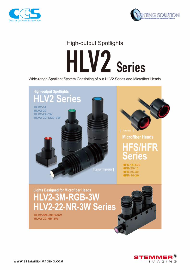
HFS-14-500
HFR-25-10
HFR-25-30
HFR-40-20
HLV2-14
HLV2-22
HLV2-22-3W
HLV2-22-1220-3W
HLV2-3M-RGB-3W
HLV2-22-NR-3W
CCS Inc.
Wide-range Spotlight System Consisting of our HLV2 Series and Microfiber Heads
High-output Spotlights
High-output Spotlights
HLV2 Series
Lights Designed for Microfiber Heads
HLV2-3M-RGB-3W
HLV2-22-NR-3W Series
Microfiber Heads
HFS/HFR Series
Design Registered
Patented
W W W. S T E M M E R- I M A G I N G . C O M
1
HLV2-14RD
HLV2-14RD-HU
HLV2-14BL
HLV2-14BL-HU
HLV2-14SW
HLV2-14SW-HU
HLV2-14GR
HLV2-14GR-HU
HLV2-22SW
HLV2-22BL
HLV2-22GR
HLV2-22RD
HLV2-22RD-1220-3W
HLV2-22GR-1220-3W
HLV2-22SW-1220-3W
HLV2-22BL-1220-3W
HLV2-22SW-3W
HLV2-22BL-3W
HLV2-22GR-3W
HLV2-22RD-3W
HLV2-22HLV2-22 HLV2-22-3WHLV2-22-3W HLV2-22-1220-3WHLV2-22-1220-3WHLV2-14HLV2-14
HLV2-22
HLV2-22-3W
HLV2-22-1220-3W
HLV2-14
HLV2-22-3W
HLV2-22-1220-3W
100%0 50%20% 100%0 50%
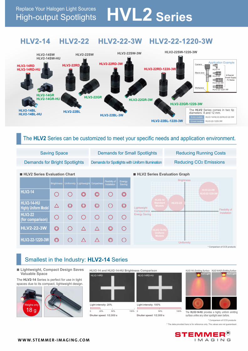
The HLV2 Series can be customized to meet your specific needs and application environment.
Saving Space Demands for Small Spotlights Reducing Running Costs
Demands for Bright Spotlights Demands for Spotlights with Uniform Illumination Reducing CO2 Emissions
■ Lightweight, Compact Design Saves
Valuable Space
The HLV2-14 Series is perfect for use in tight
spaces due to its compact, lightweight design.
Smallest in the Industry: HLV2-14 Series
Replace Your Halogen Light Sources
The HLV2-14-HU provides a highly uniform emitting surface unlike any other spotlight seen before. Shutter speed: 1/2,000 s Shutter speed: 1/2,000 s
HLV2-14 and HLV2-14-HU Brightness Comparison
HLV2-14RD HLV2-14RD-HU
HLV2-14's Emitting Surface HLV2-14-HU's Emitting Surface
* Comparison of CCS products
* The data provided here is for reference only. The values are not guaranteed.
Red Light Red Light
Camera Application Example
Macro lens
Special
Power Supply
PJ Series
Workpiece
The HLV2 Series comes in two tip diameters: 8 and 12 mm.
HLV2-14/HLV2-22/HLV2-22-3W
HLV2-22-1220-3W
8-mm models
12-mm models
■ HLV2 Series Evaluation Chart ■ HLV2 Series Evaluation Graph
HLV2-14
HLV2-14-HU
Highly Uniform Model
HLV2-22
(for comparison)
Brightness Uniformity Lightweight Compactness Flexibility of
Installation
Energy
Saving
Brightness
Lightweight
Compactness
Energy Saving
Flexibility of
Installation
HLV2-14
Standard
Models
HLV2-22-3W
HLV2-22-1220-3W
HLV2-22
* Comparison of CCS products
Uniformity
HLV2-14-HU
Uniform
Models
Weighs only
18 g
Light intensity: 20% Light intensity: 100%
HVL2 Series High-output Spotlights
W W W. S T E M M E R- I M A G I N G . C O M
2
0
20
40
60
80
100
400 450 500 550 600 650 700 750 800
100%0 35% 100%0 35%
400 500450 550 650 750600 700 800
100
80
60
40
20
0
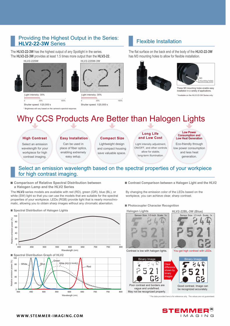
Good contrast. Image can
be recognized accurately.
Poor contrast and borders are
vague and undefined.
May not be recognized properly.
Clear difference shown by binary images
■ Comparison of Relative Spectral Distribution between
a Halogen Lamp and the HLV2 Series
■ Contrast Comparison between a Halogen Light and the HLV2
■ Photocoupler Character Recognition
HLV2-22BL-3W (Blue) Halogen Lights
Sensor Size: 1/3 inch Scale: 1x Sensor Size: 1/3 inch Scale: 1x
You get high contrast with LEDs. Contrast is low with halogen lights.
Rela
tive e
mis
sio
n p
ow
er
(%)
■ Spectral Distribution of Halogen Lights
Wavelength (nm)
By changing the emission color of the LEDs based on the
workpiece, you can achieve clear, sharp contrast.
The HLV2-series models are available with red (RD), green (GR), blue (BL), or
white (SW) light so that you can use the models that are suitable for the spectral
properties of your workpiece. LEDs (RGB) provide light that is nearly monochro-
matic, allowing you to obtain sharp images without any chromatic aberration.
The flat surface on the back end of the body of the HLV2-22-3W
has M3 mounting holes to allow for flexible installation.
The HLV2-22-3W has the highest output of any Spotlight in the series.
The HLV2-22-3W provides at least 1.5 times more output than the HLV2-22.
Flexible Installation Providing the Highest Output in the Series: HLV2-22-3W Series
Select an emission wavelength based on the spectral properties of your workpiece for high contrast imaging.
M3 mounting holes
These M3 mounting holes enable easy installation in a variety of applications.
HLV2-22SW HLV2-22SW-3W
Why CCS Products Are Better than Halogen Lights
High Contrast
Select an emission
wavelength for your
workpiece for high
contrast imaging.
Easy Installation
Can be used in
place of fiber optics,
enabling extremely
easy setup.
Compact Size
Lightweight design
and compact housing
save valuable space.
Low Power
Consumption and
Low Heat Generation
Eco-friendly through
low power consumption
and less heat
generation.
Long Life
and Low Cost
Light intensity adjustment,
ON/OFF, and other controls
allow for stable,
long-term illumination.
* The data provided here is for reference only. The values are not guaranteed.
* Brightness will vary based on the camera's spectral response.
* Available on the HLV2-22-3W Series only. Light intensity: 35%
Shutter speed: 1/20,000 s
Light intensity: 35%
Shutter speed: 1/20,000 s
Red
White (HLV2-14-HU)
Rela
tive e
mis
sio
n p
ow
er
(%)
White Blue
Green
Wavelength (nm)
■ Spectral Distribution Graph of HLV2
Binary Image Binary Image
W W W. S T E M M E R- I M A G I N G . C O M
3
1.4 W
100W
0 100 (W)10 20 30 40 50 60 70 80 90
HLV2-22
0
HLV2
5,000 10,000 15,000 20,000
0 5,000 10,000 15,000 20,0000
20
40
60
80
100
HLV2
1 2 3 4 5 6 7 8 9 10 11 12 13 14 15 16 17 18 19 20 21
6.7 kgCO2
13.4 kgCO2
20.1 kgCO2
47.95 kgCO2
95.9 kgCO2
143.85 kgCO2
*2
*1
0
50,000
100,000
150,000
200,000
0
40
20
60
80
100
150 (kgCO2)
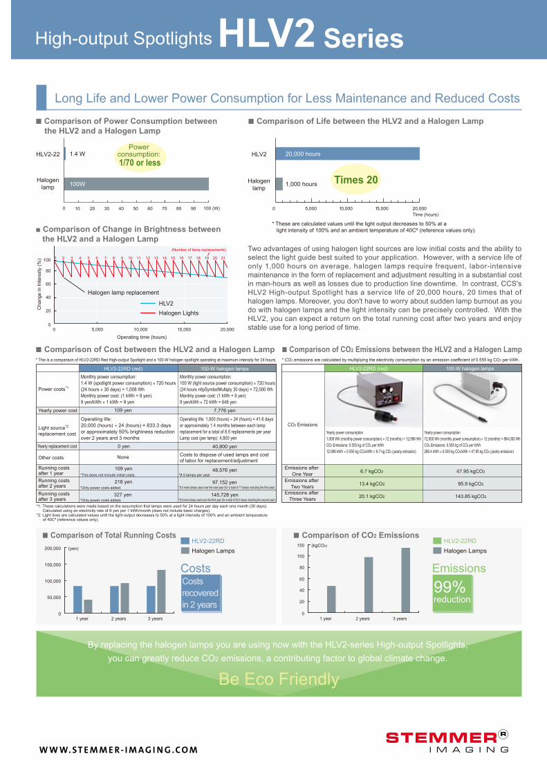
■ Comparison of Cost between the HLV2 and a Halogen Lamp ■ Comparison of CO2 Emissions between the HLV2 and a Halogen Lamp
Two advantages of using halogen light sources are low initial costs and the ability to
select the light guide best suited to your application. However, with a service life of
only 1,000 hours on average, halogen lamps require frequent, labor-intensive
maintenance in the form of replacement and adjustment resulting in a substantial cost
in man-hours as well as losses due to production line downtime. In contrast, CCS's
HLV2 High-output Spotlight has a service life of 20,000 hours, 20 times that of
halogen lamps. Moreover, you don't have to worry about sudden lamp burnout as you
do with halogen lamps and the light intensity can be precisely controlled. With the
HLV2, you can expect a return on the total running cost after two years and enjoy
stable use for a long period of time.
■ Comparison of Power Consumption between
the HLV2 and a Halogen Lamp
■ Comparison of Change in Brightness between
the HLV2 and a Halogen Lamp
*1: These calculations were made based on the assumption that lamps were used for 24 hours per day each one month (30 days). Calculated using an electricity rate of 9 yen per 1 kWh/month (does not include basic charges).
*2: Light lives are calculated values until the light output decreases to 50% at a light intensity of 100% and an ambient temperature of 40Cº (reference values only).
3 years 2 years 1 year
By replacing the halogen lamps you are using now with the HLV2-series High-output Spotlights,
you can greatly reduce CO2 emissions, a contributing factor to global climate change.
Be Eco Friendly
■ Comparison of Life between the HLV2 and a Halogen Lamp
* These are calculated values until the light output decreases to 50% at a
light intensity of 100% and an ambient temperature of 40Cº (reference values only).
High-output Spotlights HLV2 Series
Long Life and Lower Power Consumption for Less Maintenance and Reduced Costs
Halogen
lamp
Power consumption:
1/70 or less
Halogen
lamp Times 20 1,000 hours
Time (hours)
20,000 hours
Halogen lamp replacement
Halogen Lights
(Number of lamp replacements)
Operating time (hours)
* This is a comparison of HLV2-22RD Red High-output Spotlight and a 100-W halogen spotlight operating at maximum intensity for 24 hours.
Monthly power consumption:
1.4 W (spotlight power consumption) × 720 hours
(24 hours × 30 days) = 1,008 Wh
Monthly power cost: (1 kWh = 9 yen)
9 yen/kWh × 1 kWh = 9 yen
Monthly power consumption:
100 W (light source power consumption) × 720 hours
(24 hours ntlpSymbolMultiply 30 days) = 72,000 Wh
Monthly power cost: (1 kWh = 9 yen)
9 yen/kWh × 72 kWh = 648 yen
109 yen
0 yen
Operating life:
20,000 (hours) ÷ 24 (hours) = 833.3 days
or approximately 50% brightness reduction
over 2 years and 3 months
Power costs
Running costs after 1 year *This does not include initial costs.
*Only power costs added.
*Only power costs added.
Operating life: 1,000 (hours) ÷ 24 (hours) = 41.6 days
or approximately 1.4 months between each lamp
replacement for a total of 8.5 replacements per year
Lamp cost (per lamp): 4,800 yen
Costs to dispose of used lamps and cost
of labor for replacement/adjustment
48,576 yen
97,152 yen
145,728 yen
*8.5 lamps per year
*8.5 more lamps used over the next year (for a total of 17 lamps including the first year)
*8.5 more lamps used over the third year (for a total of 25.5 lamps including the second year)
7,776 yen
40,800 yen
* CO2 emissions are calculated by multiplying the electricity consumption by an emission coefficient of 0.555 kg CO2 per kWh.
Yearly power consumption
1,008 Wh (monthly power consumption) × 12 (months) = 12,096 Wh
CO2 Emissions: 0.555 kg of CO2 per kWh
12.096 kWh × 0.555 kg CO2/kWh = 6.7 kg CO2 (yearly emission)
Yearly power consumption
72,000 Wh (monthly power consumption) × 12 (months) = 864,000 Wh
CO2 Emissions: 0.555 kg of CO2 per kWh
286.4 kWh × 0.555 kg CO2/kWh = 47.95 kg CO2 (yearly emission)
Emissions after
One Year
CO2 Emissions
HLV2-22RD (red) 100-W halogen lamps HLV2-22RD (red) 100-W halogen lamps
■ Comparison of Total Running Costs
3 years 2 years 1 year
(yen)
Costs Costs
recovered
in 2 years
■ Comparison of CO2 Emissions HLV2-22RD
Halogen Lamps
Emissions
99% reduction
HLV2-22RD
Halogen Lamps
Change in Inte
nsity (
%)
Yearly power cost
Other costs
Light source
replacement cost
Yearly replacement cost
Running costs after 2 years
Running costs after 3 years
327 yen
None
109 yen
218 yen Emissions after
Two Years
Emissions after
Three Years
W W W. S T E M M E R- I M A G I N G . C O M
4
HLV2-14RD
HLV2-14SW
HLV2-14BL
HLV2-14GR
HLV2-14RD-HU
HLV2-14SW-HU
HLV2-14BL-HU
HLV2-14GR-HU
HLV2-22RD
HLV2-22SW
HLV2-22BL
HLV2-22GR
HLV2-22RD-3W
HLV2-22SW-3W
HLV2-22BL-3W
HLV2-22GR-3W
HLV2-22RD-1220-3W
HLV2-22SW-1220-3W
HLV2-22BL-1220-3W
HLV2-22GR-1220-3W
1004853
1004854
1004855
1004856
1004857
1004858
1004859
1004860
1004512
1004513
1004514
1004515
1004516
1004517
1004518
1004519
1004524
1004525
1004526
1004527
645 nm
5,300 K
465 nm
520 nm
645 nm
4,700 K
465 nm
520 nm
645 nm
5,300 K
465 nm
520 nm
645 nm
5,300 K
465 nm
520 nm
645 nm
5,300 K
465 nm
520 nm
0.9 W
1.4 W
2.8 W
18 g
37 g
41 g
42 g
14
0 -0.1
8-0
.1-0
.2
20
14
13
7
28
12
20
12
14
0 -0.1
8-0
.1-0
.2
50
(8.5)
8
HLV2-14/HLV2-14-HU HLV2-22
HLV2-22-3W HLV2-22-1220-3W
62
(20.5)
14
0 -0.1
8-0
.1-0
.2 12 8 14 14
62
20
12
-0.0
5-0
.10
(20.5)
FCB-1/-2-/-3-/5
(1m/2m/3m/5m)
FRCB-1/-2-/-3-/5
(1m/2m/3m/5m)
dia
.
dia
.
dia
.
dia
.
dia
.
dia
.
dia
.
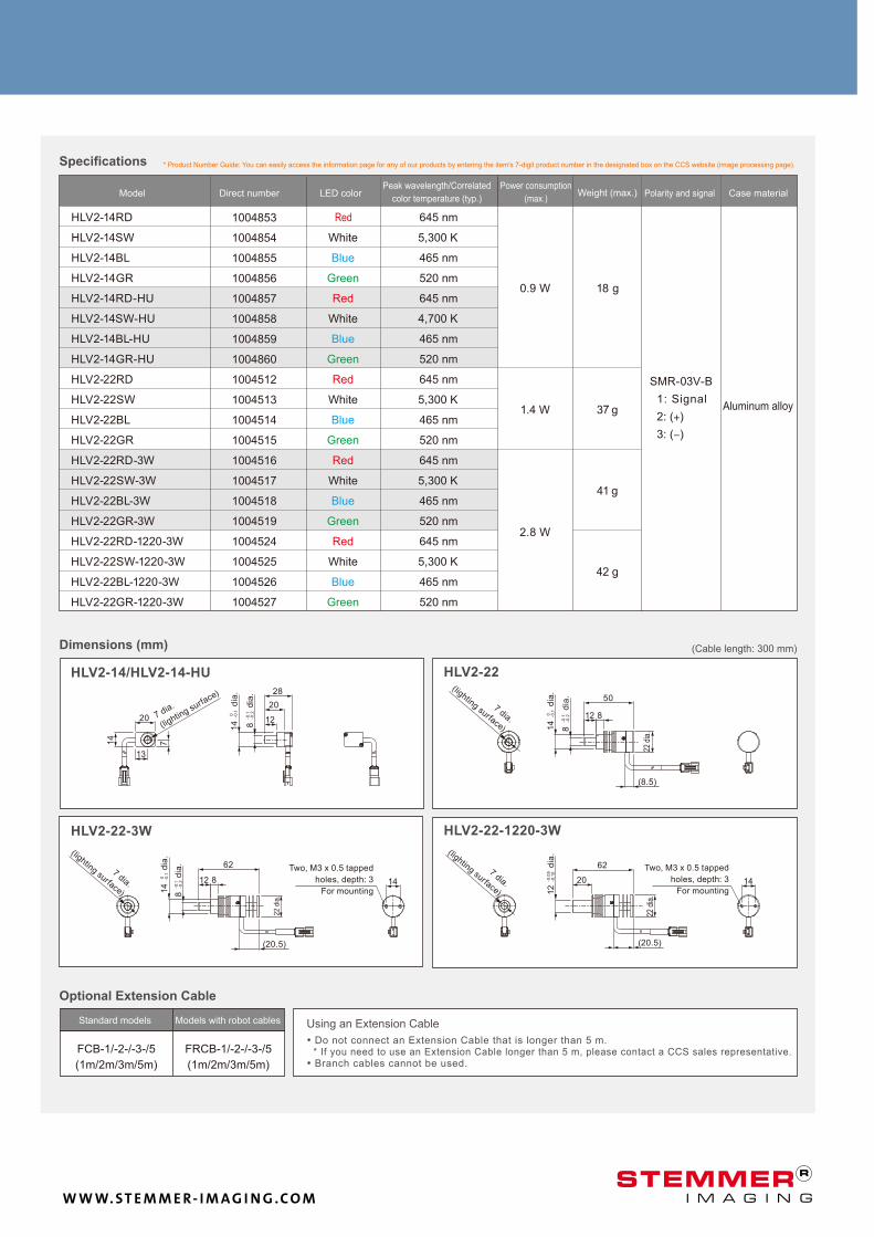
Specifications
Red
SMR-03V-B
2: (+)
3: (−)
1: Signal Aluminum alloy
White
Blue
Green
Red
White
Blue
Green
Red
White
Blue
Green
Red
White
Blue
Green
Red
White
Blue
Green
Dimensions (mm) (Cable length: 300 mm)
Model Direct number LED color Polarity and signal Case material
* Product Number Guide: You can easily access the information page for any of our products by entering the item's 7-digit product number in the designated box on the CCS website (image processing page).
7 dia.
(lightin
g surface)
7 dia.
(lighting surface)
22 d
ia.
7 dia.
(lighting surface)
Two, M3 x 0.5 tapped
holes, depth: 3
For mounting
7 dia.
(lighting surface)
Two, M3 x 0.5 tapped
holes, depth: 3
For mounting
Standard models Models with robot cables Using an Extension Cable
• Do not connect an Extension Cable that is longer than 5 m. * If you need to use an Extension Cable longer than 5 m, please contact a CCS sales representative. • Branch cables cannot be used.
Optional Extension Cable
Peak wavelength/Correlated
color temperature (typ.)
Power consumption
(max.) Weight (max.)
22 d
ia.
22 d
ia.
W W W. S T E M M E R- I M A G I N G . C O M
5
HFS-14-500
HFR-25-10
HFR-25-30
HFRHFR
HFR-25-30
HFR-25-10
HFR-40-20*
HFS-14-500
HFS
10 150 5 20 25 30 35 40 45 50 55 600%
10%
20%
30%
40%
50%
60%
70%
80%
90%
100%
HFR-40-20
HFR-25-30
HFR-25-10
302010
HFS
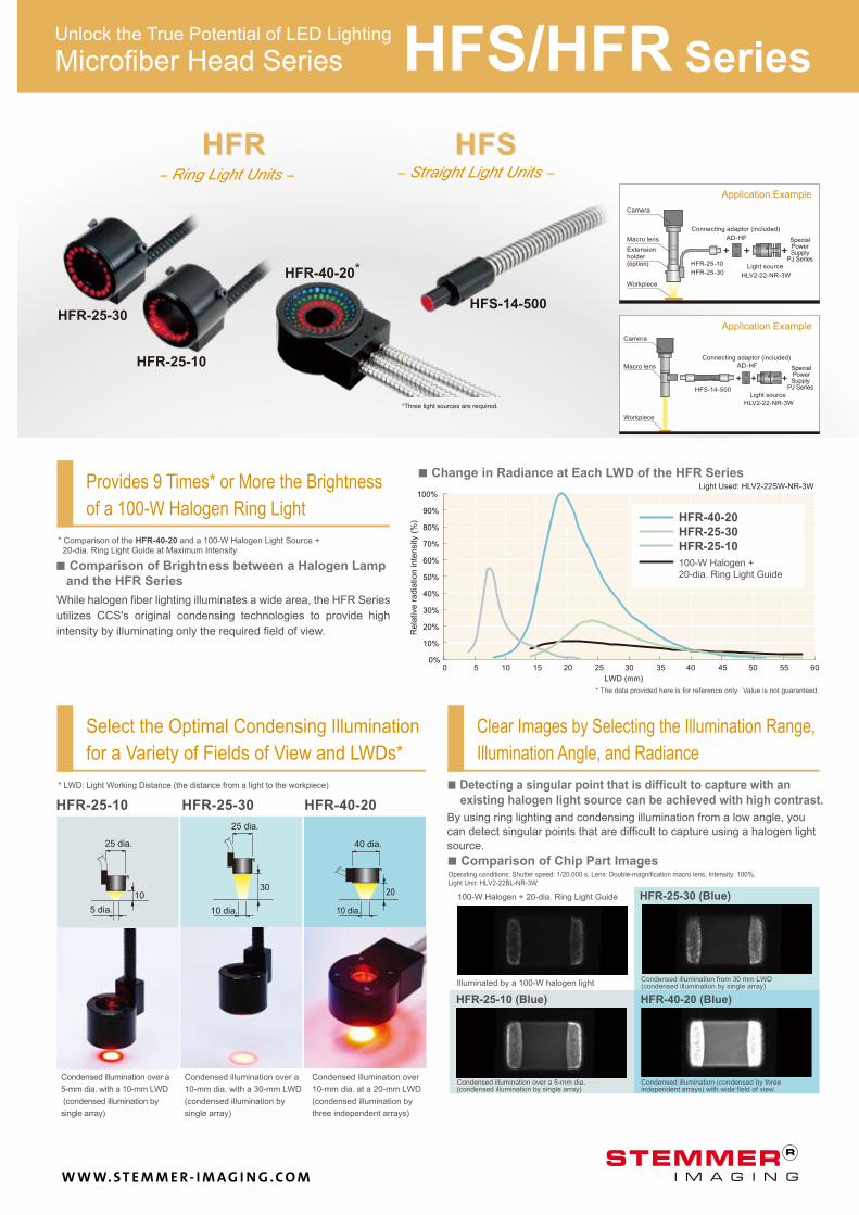
Clear Images by Selecting the Illumination Range,
Illumination Angle, and Radiance
Select the Optimal Condensing Illumination
for a Variety of Fields of View and LWDs*
* LWD: Light Working Distance (the distance from a light to the workpiece) ■ Detecting a singular point that is difficult to capture with an
existing halogen light source can be achieved with high contrast.
By using ring lighting and condensing illumination from a low angle, you
can detect singular points that are difficult to capture using a halogen light
source.
HFR-25-30HFR-25-10 HFR-40-20
Operating conditions: Shutter speed: 1/20,000 s, Lens: Double-magnification macro lens, Intensity: 100%,
Light Unit: HLV2-22BL-NR-3W
Illuminated by a 100-W halogen light Condensed illumination from 30 mm LWD (condensed illumination by single array)
Condensed illumination over a 5-mm dia. (condensed illumination by single array)
Condensed illumination (condensed by three independent arrays) with wide field of view
100-W Halogen + 20-dia. Ring Light Guide HFR-25-30 (Blue)
HFR-25-10 (Blue) HFR-40-20 (Blue)
■ Comparison of Chip Part Images
Condensed illumination over a
10-mm dia. with a 30-mm LWD
(condensed illumination by
single array)
Condensed illumination over a
5-mm dia. with a 10-mm LWD
(condensed illumination by
single array)
Condensed illumination over
10-mm dia. at a 20-mm LWD
(condensed illumination by
three independent arrays)
− Straight Light Units −− Ring Light Units −
*Three light sources are required.
Application Example
Application Example
While halogen fiber lighting illuminates a wide area, the HFR Series
utilizes CCS's original condensing technologies to provide high
intensity by illuminating only the required field of view.
■ Comparison of Brightness between a Halogen Lamp
and the HFR Series
* Comparison of the HFR-40-20 and a 100-W Halogen Light Source + 20-dia. Ring Light Guide at Maximum Intensity
LWD (mm)
■ Change in Radiance at Each LWD of the HFR Series Provides 9 Times* or More the Brightness
of a 100-W Halogen Ring Light
* The data provided here is for reference only. Value is not guaranteed.
Unlock the True Potential of LED Lighting
100-W Halogen +
20-dia. Ring Light Guide
5 dia.
25 dia.
10 dia.
25 dia.
40 dia.
10 dia.
Light Used: HLV2-22SW-NR-3W
Workpiece
Camera
Macro lens Special Power Supply
PJ Series
Connecting adaptor (included)
AD-HF
Workpiece
Special Power Supply
PJ Series
Connecting adaptor (included)
AD-HF
Light source
HLV2-22-NR-3W
Camera
Macro lens
Extension holder (option)
Light source
HLV2-22-NR-3W
HFS/HFR Series
Re
lative
ra
dia
tio
n in
ten
sity (
%)
Microfiber Head Series
W W W. S T E M M E R- I M A G I N G . C O M
6
30
25
27
φ14
38 500 28
12 8 8
18
14
15
45
LW
D=
20
23
21.5
12 23
35 500
14
18
27
39
23 16
25
148 8
8
14
10
dia
.
0 -0.1
8 0 -0
.1
0 -0.1
0 -0.1
20
P.C.D
.20
15
19
13
16 1214
25
8 8
18
15 9
8
918
20
7
27
500 +300
16 +0.102
7
HFR-25-1060 g
250 g
115 g
HFR-25-30
HFR-40-20
HFS-14-500
1000127
1000129
1000134
1000148
HFR-25-10/30
HFR-40-20HFS-14-500
HFR-25-10
HFR-25-30
HFR-25-10/HFR-25-30
HFS-14-500
HFR-40-20
dia.
dia
.
dia.
dia
.
dia
.
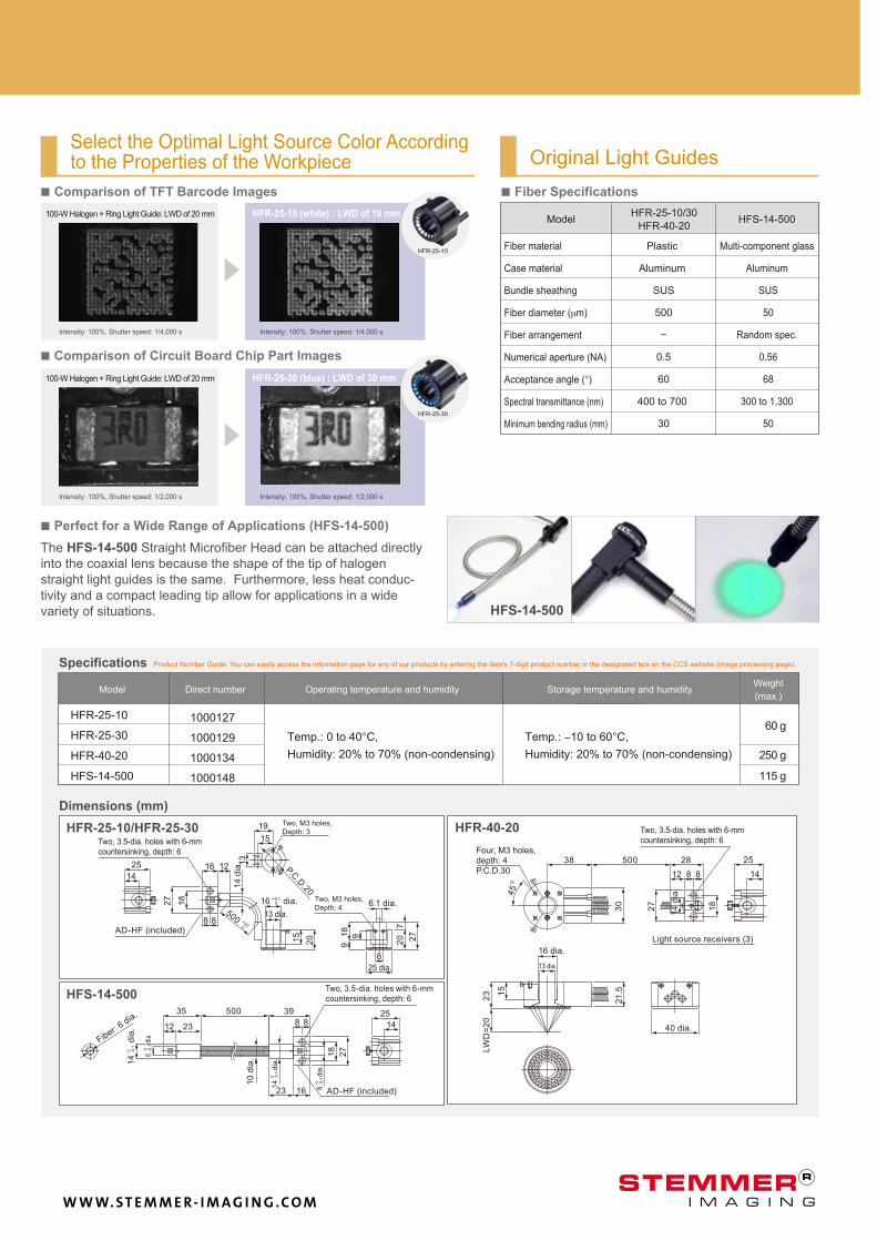
Specifications
Dimensions (mm)
Select the Optimal Light Source Color According to the Properties of the Workpiece Original Light Guides
HFS-14-500
■ Perfect for a Wide Range of Applications (HFS-14-500)
■ Fiber Specifications
The HFS-14-500 Straight Microfiber Head can be attached directly
into the coaxial lens because the shape of the tip of halogen
straight light guides is the same. Furthermore, less heat conduc-
tivity and a compact leading tip allow for applications in a wide
variety of situations.
HFR-25-30 (blue) : LWD of 30 mm
■ Comparison of Circuit Board Chip Part Images
HFR-25-10 (white) : LWD of 10 mm
■ Comparison of TFT Barcode Images
100-W Halogen + Ring Light Guide: LWD of 20 mm
100-W Halogen + Ring Light Guide: LWD of 20 mm
Intensity: 100%, Shutter speed: 1/4,000 s Intensity: 100%, Shutter speed: 1/4,000 s
Intensity: 100%, Shutter speed: 1/2,000 s Intensity: 100%, Shutter speed: 1/2,000 s
Product Number Guide: You can easily access the information page for any of our products by entering the item's 7-digit product number in the designated box on the CCS website (image processing page).
Model Direct number Operating temperature and humidity
Temp.: 0 to 40°C,
Humidity: 20% to 70% (non-condensing)
Temp.: −10 to 60°C,
Humidity: 20% to 70% (non-condensing)
Storage temperature and humidity Weight
(max.)
Fiber material
Case material
Bundle sheathing
Fiber diameter (µm)
Fiber arrangement
Numerical aperture (NA)
Acceptance angle (°)
Spectral transmittance (nm)
Minimum bending radius (mm)
Model
Plastic
Aluminum
SUS
500
−
0.5
60
400 to 700
30
Multi-component glass
Aluminum
SUS
50
Random spec.
0.56
68
300 to 1,300
50
Two, 3.5-dia. holes with 6-mm countersinking, depth: 6
Two, M3 holes,
Depth: 3
14
dia
.
AD-HF (included)
Two, M3 holes,
Depth: 4 6.1 dia.
25 dia.
13 dia.
Fiber: 6 d
ia.
Two, 3.5-dia. holes with 6-mm countersinking, depth: 6
AD-HF (included)
Four, M3 holes, depth: 4 P.C.D.30
Two, 3.5-dia. holes with 6-mm countersinking, depth: 6
Light source receivers (3)
14
dia
.
16 dia.
13 dia.
40 dia.
W W W. S T E M M E R- I M A G I N G . C O M
HLV2-22-NR-3WHLV2-3M-RGB-3W
7
HFS-14-500
HFR-25-10
HFR-25-30
HFS-14-500
HFR-25-10
HFR-25-30
HLV2-3M-RGB-3W HLV2-22-NR-3W
HLV2-22SW-NR-3W
HLV2-22GR-NR-3W
HLV2-22RD-NR-3W
HLV2-22BL-NR-3WHLV2-3M-RGB-3W
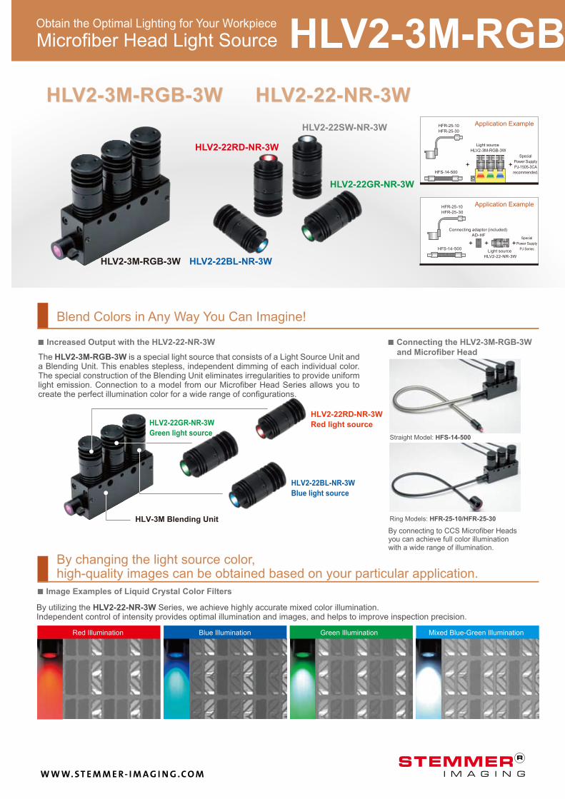
■ Image Examples of Liquid Crystal Color Filters
Red Illumination Green Illumination Blue Illumination Mixed Blue-Green Illumination
By utilizing the HLV2-22-NR-3W Series, we achieve highly accurate mixed color illumination. Independent control of intensity provides optimal illumination and images, and helps to improve inspection precision.
By changing the light source color, high-quality images can be obtained based on your particular application.
■ Connecting the HLV2-3M-RGB-3W
and Microfiber Head
By connecting to CCS Microfiber Heads you can achieve full color illumination with a wide range of illumination.
Ring Models: HFR-25-10/HFR-25-30
Straight Model: HFS-14-500
The HLV2-3M-RGB-3W is a special light source that consists of a Light Source Unit and a Blending Unit. This enables stepless, independent dimming of each individual color. The special construction of the Blending Unit eliminates irregularities to provide uniform light emission. Connection to a model from our Microfiber Head Series allows you to create the perfect illumination color for a wide range of configurations.
■ Increased Output with the HLV2-22-NR-3W
HLV-3M Blending Unit
HLV2-22RD-NR-3W
Red light source HLV2-22GR-NR-3W
Green light source
HLV2-22BL-NR-3W
Blue light source
Blend Colors in Any Way You Can Imagine!
Obtain the Optimal Lighting for Your Workpiece
Application Example
Special
Power Supply
PJ-1505-3CA
recommended.
Light source
HLV2-3M-RGB-3W
Application Example
Connecting adaptor (included)
AD-HFSpecial
Power Supply
PJ Series Light source
HLV2-22-NR-3W
HLV2-3M-RGB-3W/HLV2-22-NR-3W Series Microfiber Head Light Source
W W W. S T E M M E R- I M A G I N G . C O M
8
HLV2-22RD-NR-3W 645 nm
HLV2-22SW-NR-3W 5,300 K
HLV2-22BL-NR-3W 465 nm
HLV2-22GR-NR-3W 520 nm
232 g
645 nm
HLV2-3M-RGB-3W 465 nm
520 nm
1004520
1004521
1004522
1004523
1004528
2: (+)
3: (−)
37 g
8.4 W
2.8 W
HLV2-22-NR-3W HLV2-3M-RGB-3W
22 dia.
13 72
0
8312
26.530
1427.527.5
31
HLV2-22RD-NR-3W
HLV2-22GR-NR-3W
HLV2-22BL-NR-3W
10
113
7
14
(1.2)26
39
377
418
(20.5)
22 d
ia.1
40 -0
.1
45
6 14
FCB-1/-2-/-3-/5
(1m/2m/3m/5m)
FRCB-1/-2-/-3-/5
(1m/2m/3m/5m)
dia
.
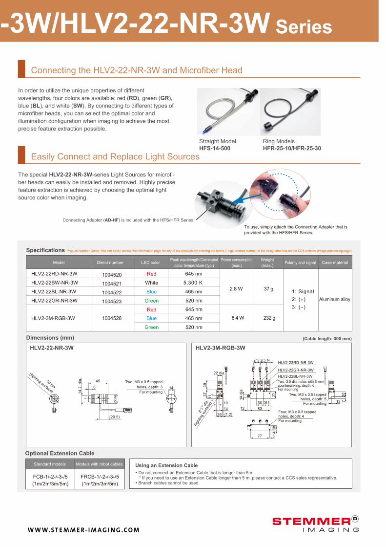
Connecting the HLV2-22-NR-3W and Microfiber Head
In order to utilize the unique properties of different
wavelengths, four colors are available: red (RD), green (GR),
blue (BL), and white (SW). By connecting to different types of
microfiber heads, you can select the optimal color and
illumination configuration when imaging to achieve the most
precise feature extraction possible.
Easily Connect and Replace Light Sources
The special HLV2-22-NR-3W-series Light Sources for microfi-
ber heads can easily be installed and removed. Highly precise
feature extraction is achieved by choosing the optimal light
source color when imaging.
To use, simply attach the Connecting Adapter that is
provided with the HFS/HFR Series.
Connecting Adapter (AD-HF) is included with the HFS/HFR Series
Straight Model
HFS-14-500
Ring Models
HFR-25-10/HFR-25-30
Specifications Product Number Guide: You can easily access the information page for any of our products by entering the item's 7-digit product number in the designated box on the CCS website (image processing page).
Model Direct number LED color Polarity and signal Case material Peak wavelength/Correlated
color temperature (typ.)
Power consumption
(max.)
Weight
(max.)
Red
White
Blue
Green
Red
Blue
Green
1: Signal
Aluminum alloy
Dimensions (mm) (Cable length: 300 mm)
10 dia.
(lighting surface)
Two, M3 x 0.5 tapped
holes, depth: 3
For mounting
8
dia
.
(ligh
ting
surfac
e)
Four, M3 x 0.5 tapped holes, depth: 4 For mounting
Two, M3 x 0.5 tapped holes, depth: 5
For mounting
Two, 3.5-dia. holes with 6-mm countersinking, depth: 6 For mounting
14
dia
.
Optional Extension Cable
Standard models Models with robot cables Using an Extension Cable
• Do not connect an Extension Cable that is longer than 5 m. * If you need to use an Extension Cable longer than 5 m, please contact a CCS sales representative.
• Branch cables cannot be used.
HLV2-3M-RGB-3W/HLV2-22-NR-3W Series
+0.1
0
0
W W W. S T E M M E R- I M A G I N G . C O M
9
A
75
38
(8)
L1 L2
Remote
Manual
Remote ControlIntensity
Hi
Lo
Control
DC24V IN
Range
PJ-1505-2CD24
142
L1 L2
42.5 55
82
0
120
37.5
37.5
11 11
5
0 10
5
0 101
2
34 6
7
8
9 1
2
34 6
9
7
8
L2
ControlRange
RemoteHi
Lo Manual
5
Intensity
Power
L1
62
16 54 (16)
PJ-1505-2CA
1210812
132
16
54
(16)
86
16100(16)
A
Remote Control
L2 L1
FG
100-240V50/60Hz 27VA
Output
PJ-1505-2CA
PJ-1505-3CA
100
90
80
70
60
50
40
30
20
10
0
100
90
80
70
60
50
40
30
20
10
0
10 2 3 4 510 2 3 4 5
PJ-1505-2CA 640 g
660 g
380 g
PJ-1505-3CA
PJ-1505-2CD24
PJ-1505-3CD24
2000131
2000136
2000134
2000139
2
3
2
3
DC 5.5 V
PJ-1505-3CD24
PJ-1505-2CD24
PJ-1505-2CD24PJ-1505-2CA
HLV2 Series Light Sources
100 to 240-VAC Models 24-V DC Models
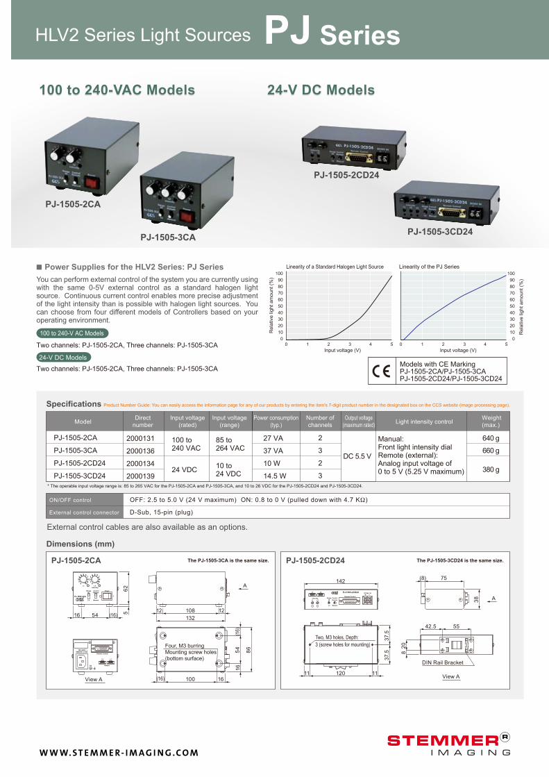
You can perform external control of the system you are currently using with the same 0-5V external control as a standard halogen light source. Continuous current control enables more precise adjustment of the light intensity than is possible with halogen light sources. You can choose from four different models of Controllers based on your operating environment.
■ Power Supplies for the HLV2 Series: PJ Series
100 to 240-V AC Models
Two channels: PJ-1505-2CA, Three channels: PJ-1505-3CA
Two channels: PJ-1505-2CA, Three channels: PJ-1505-3CA
24-V DC Models
Linearity of a Standard Halogen Light Source Linearity of the PJ Series
Input voltage (V) Input voltage (V)
Models with CE Marking PJ-1505-2CA/PJ-1505-3CAPJ-1505-2CD24/PJ-1505-3CD24
Product Number Guide: You can easily access the information page for any of our products by entering the item's 7-digit product number in the designated box on the CCS website (image processing page). Specifications
Model Input voltage
(rated)
Input voltage
(range)
Power consumption
(typ.)
Weight
(max.)
Direct
number
Number of
channels
Output voltage
(maximum rated) Light intensity control
100 to 240 VAC
24 VDC
85 to 264 VAC
10 to 24 VDC
Manual: Front light intensity dial Remote (external): Analog input voltage of 0 to 5 V (5.25 V maximum)
* The operable input voltage range is: 85 to 265 VAC for the PJ-1505-2CA and PJ-1505-3CA, and 10 to 26 VDC for the PJ-1505-2CD24 and PJ-1505-3CD24.
ON/OFF control
External control connector
OFF: 2.5 to 5.0 V (24 V maximum) ON: 0.8 to 0 V (pulled down with 4.7 KΩ)
D-Sub, 15-pin (plug)
Dimensions (mm)
External control cables are also available as an options.
The PJ-1505-3CA is the same size.
View A
Four, M3 burring Mounting screw holes (bottom surface)
The PJ-1505-3CD24 is the same size.
DIN Rail Bracket
View A
Two, M3 holes, Depth:
3 (screw holes for mounting)
27 VA
37 VA
10 W
14.5 W
Rela
tive lig
ht am
ount (%
)
Rela
tive lig
ht am
ount (%
)
PJ Series
100 to 240-VAC Models 24-V DC Models
W W W. S T E M M E R- I M A G I N G . C O M
10
HL-30
HL-24-21
WD40mm WD30mm
HD-HFR-25-1618
WD40mm
WD10mm
WD60mm
WD10mm
HD-HFR-25-1640
WD60mm
WD30mm
HD-HFR-25-1618
2
18 15
17
2
18 15
17
2
40 15
39
HL-24-21HL-30
55
15 7
18
12
3.5
M22.5 P0.5
58
911
M22.5*P0.522 18
10
12
50 100 150 200 250 300WD (mm) 0
14 dia.
20 dia.
31 dia.
37 dia.
46 dia.
60 dia.
60 dia.
83 dia.
76 dia.
108 dia.
90 dia.
128 dia.
10 dia.
27 dia.
12 dia.
36 dia.
22 dia.
45 dia.
35 dia.
55 dia.
45 dia.
65 dia.
60 dia.
77 dia.HL-24-21
HL-30
HD-HFR-25-1618
HFR-25-10
HD-HFR-25-1640
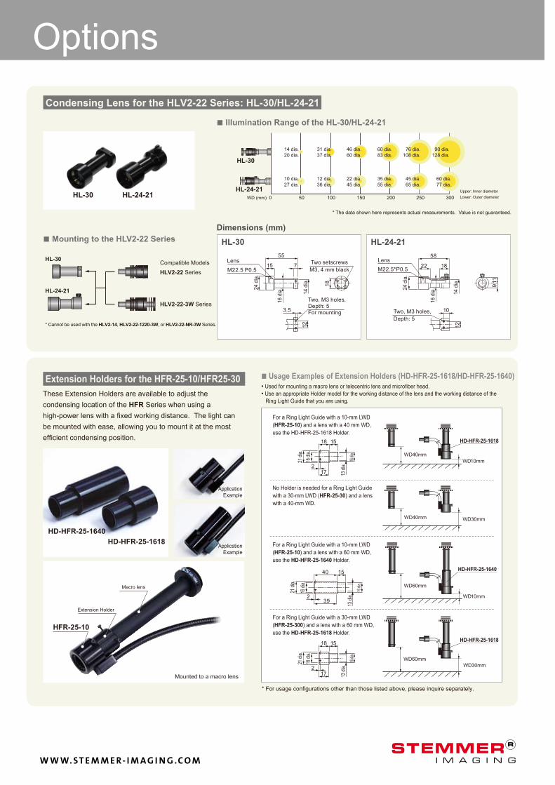
These Extension Holders are available to adjust the
condensing location of the HFR Series when using a
high-power lens with a fixed working distance. The light can
be mounted with ease, allowing you to mount it at the most
efficient condensing position.
■ Usage Examples of Extension Holders (HD-HFR-25-1618/HD-HFR-25-1640) • Used for mounting a macro lens or telecentric lens and microfiber head.
• Use an appropriate Holder model for the working distance of the lens and the working distance of the
Ring Light Guide that you are using.
* For usage configurations other than those listed above, please inquire separately.
Condensing Lens for the HLV2-22 Series: HL-30/HL-24-21
Options
HL-30 HL-24-21
Dimensions (mm)
■ Mounting to the HLV2-22 Series
* Cannot be used with the HLV2-14, HLV2-22-1220-3W, or HLV2-22-NR-3W Series.
Compatible Models
HLV2-22 Series
HLV2-22-3W Series
Lens 2
4 d
ia.
16
dia
.
14
dia
.
Two setscrews
M3, 4 mm black
Two, M3 holes, Depth: 5 For mounting
24
dia
.
16
dia
.
Lens
14
dia
.
Two, M3 holes,
Depth: 5
For a Ring Light Guide with a 10-mm LWD
(HFR-25-10) and a lens with a 40 mm WD,
use the HD-HFR-25-1618 Holder.
No Holder is needed for a Ring Light Guide
with a 30-mm LWD (HFR-25-30) and a lens
with a 40-mm WD.
For a Ring Light Guide with a 10-mm LWD
(HFR-25-10) and a lens with a 60 mm WD,
use the HD-HFR-25-1640 Holder.
For a Ring Light Guide with a 30-mm LWD
(HFR-25-300) and a lens with a 60 mm WD,
use the HD-HFR-25-1618 Holder.
13 d
ia.
16 d
ia.
16 d
ia.
21 d
ia.
21 d
ia.
16 d
ia.
13 d
ia.
16 d
ia.
13 d
ia.
16 d
ia.
16 d
ia.
21 d
ia.
Upper: Inner diameter
Lower: Outer diameter
Extension Holders for the HFR-25-10/HFR25-30
Extension Holder
Macro lens
Mounted to a macro lens
Application Example
Application Example
■ Illumination Range of the HL-30/HL-24-21
* The data shown here represents actual measurements. Value is not guaranteed.
W W W. S T E M M E R- I M A G I N G . C O M
SE-18 seriesSE-18 seriesSE-16 seriesSE-16 series
100%50%0 100%50%0
Notes
Carefully read the product's instruction manual before use to ensure correct operation. Product specifications and design are subject to change without notice.
Examples of workpiece imaging in this catalog are a guide that may be informative for choosing illuminations. Please check the functions of the equipment and requirements when choosing.
Headquarters
Shimodachiuri-agaru, Karasuma-dori, Kamigyo-ku, Kyoto 602-8011 Japan
Phone: +81-75-415-8284 / Fax: +81-75-415-8278
URL: http://www.ccs-grp.com E-mail: [email protected]
Copyright © 2010 CCS Inc. All Rights Reserved.
Descriptions in this document are based on information available as of November 2010. 01002-00-1011-HLV2 catalog
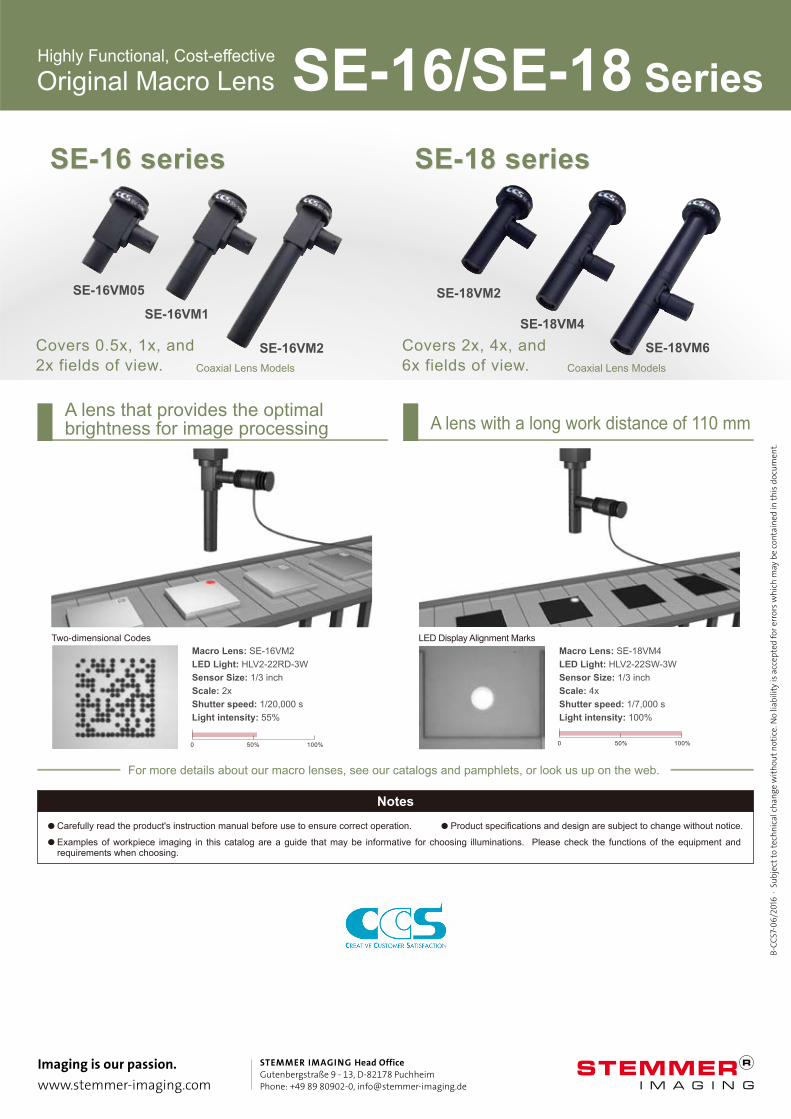
A lens that provides the optimal brightness for image processing A lens with a long work distance of 110 mm
Macro Lens: SE-16VM2
LED Light: HLV2-22RD-3W
Sensor Size: 1/3 inch
Scale: 2x
Shutter speed: 1/20,000 s
Light intensity: 55%
Two-dimensional Codes
Macro Lens: SE-18VM4
LED Light: HLV2-22SW-3W
Sensor Size: 1/3 inch
Scale: 4x
Shutter speed: 1/7,000 s
Light intensity: 100%
LED Display Alignment Marks
SE-16VM05
SE-16VM1
SE-16VM2
Coaxial Lens Models
Covers 0.5x, 1x, and
2x fields of view. Coaxial Lens Models
SE-18VM2
SE-18VM4
SE-18VM6Covers 2x, 4x, and
6x fields of view.
Highly Functional, Cost-effective
For more details about our macro lenses, see our catalogs and pamphlets, or look us up on the web.
Original Macro Lens SE-16/SE-18 Series
Imaging is our passion. www.stemmer-imaging.com
STEMMER IMAGING Head OfficeGutenbergstraße 9 - 13, D-82178 PuchheimPhone: +49 89 80902-0, [email protected]
B-CC
S7-0
6/20
16 ∙
Sub
ject
to te
chni
cal c
hang
e w
ithou
t not
ice.
No
liabi
lity
is a
ccep
ted
for e
rror
s whi
ch m
ay b
e co
ntai
ned
in th
is d
ocum
ent.