Embed Size (px)
Citation preview

®
The high performance companypresenTs The ulTimaTehigh performance valve
SER
iES
40-4
5W
afer
& l
ug B
odie
s2 1 / 2
-60"
(65-
1500
mm
)

high pERfoRmancEhigh pRESSuRE high TEmpERaTuREZERo LEaKagEbuTTERfLy vaLvES
2 1/2- 60" (65-1500mm) WafER offER bubbLE-TighT bidiREcTionaL ShuT-off and foR dEad-End SERvicE Lug bodiES offER bidiREcTionaL bubbLE-TighT ShuT-off, boTh aT fuLL RaTEd pRESSuRE
WafER/Lug bodiES: SERiES 40/41 – anSi cLaSS 150 SERiES 42/43 – anSi cLaSS 300 SERiES 44/45 – anSi cLaSS 600
TEmpERaTuRE RangE: -20°f To 500°f (-29°c To 260°c)
Bray controls is proud to offer the Bray/mccannalok line of high performance butterfly valves. This product line is recognized as a proven leader with over 30 years of successful service in process in-dustries worldwide. The Series 40’s unique, patented design received Chemical Processing’s Vaaler Award for Best Product shortly after it was introduced. The simple, innovative design offers rugged reliability and extremely easy maintenance in the field. Independent and internal tests have proven Bray/McCannalok’s superior service life capability, with bubble-tight shut-off through over 100,000 cycles. The Series 40 valves can be auto-mated inexpensively with Bray’s pneumatic and electric actuators. When compared to gate, globe, ball, diaphragm and plug valves, the Bray/McCannalok butterfly valve is significantly smaller and lighter weight, therefore installation space, time, and maintenance costs are greatly reduced. The Bray/mccannalok high Performance Valve delivers the highest quality and highest value available for your requirements.
body (a) One piece wafer body style or lug style for dead-end service. Both body styles offer bidirectional sealing as standard to full ANSI Class 150, 300 or 600 ratings. Standard body materials are either carbon steel or stainless steel for excellent corrosion resistance. Extended neck allows for 2" of pipeline insulation and easy access to stem packing adjust-ments and actuator mounting.
STEm (b) The high-strength, one piece stem is 17-4 PH Stainless Steel. The valve stem is standardized for inter-changeability of Bray actuators.
diSc (c) The disc has been engineered to maximize flow and minimize resistance, pro-viding a high Cv. 316 Stain-less Steel is standard.
TapER pinS (d)Taper pins are precisionfit into taper–reamed holes providing a positive connection of maximum strength between the valve disc and stem.
inTERnaL TRavEL STop (E) An internal travel stop has been designed to prevent over travel of the disc, minimizing possible seat damage, there-fore extending the service life of the seat.handLE and noTch pLaTE (f) The heavy–duty, spring release han-dle and 10 posi-tion notch plate allow for position-ing the valve disc to precise angle stops between the full open and full closed positions.
bLoW-ouT pRoof STEm (g)The Series 40 High Performance valve features blow-out proof stem protection. A retaining ring is installed between the machined stem groove and gland retainer step providing full retention of the stem in the unlikely event of internal stem failure. (See photo on page 3).
a
b
c
d
E
f
ih
J
2

disc in openposition
disc in closedposition
Body
seat stem
2ndoffset
1stoffset
centerlineof stem
centerlineof valve
doubLE offSET STEm and diSc dESignThe double offset design of the Series 40 assures reduced seat wear and bidirectional, zero leakage, shut off throughout the full pressure range. At the initial point of disc opening, the offset disc produces a cam–like action, pulling the disc from the seat. This cam–like action reduces seat wear and eliminates seat deformation when the disc is in the open position. When open, the disc does not contact the seat, therefore seat service life is extended and operating torques are reduced. As the valve closes, the cam–like action converts the rotary motion of the disc to a linear type motion to effectively push the disc onto the seat. The wiping action of the disc against the seat prevents undesirable material build-up from slurries or suspended solids. The taper pins carry virtually equal loads while anchoring the disc to the stem, permitting accurate disc closure for consistent sealing and positive shut off.
adJuSTabLE STEm pacKing The stem packing system features easy access to adjusting hex head nuts with-out requiring removal of the actuator. The system consists of a gland ring (h), a gland retainer (i), studs, hex head nuts and lock washers (J). A slight 1/4 turn of the hex head nuts is usually all that is required should field adjustment ever be needed. Both hex head nuts must be evenly adjusted and not overtightened.
SEaT dESignThE hEaRT of ThE SERiES 40 vaLvE The unique, two-part seat assembly consists of a resilient energizer (m) which is totally encapsulated by the RTFE* seat (n). The assembly is locked in the body recess by a full–faced seat retainer (o). This simple, reliable and proven combination results in many exclusive advantages, including:• The energizer is completely isolated from all contact with the line media by the RTFE seat.• Serrations in the seat retainer and body recess secure the seat assembly in place regardless of disc position. • The full–faced retainer is bolted to the body, locking the seat in the correct position. The seat is secured even without the mating flange. • The closely confined and well sup- ported seat is energized by the disc and line pressure. The higher the pressure, the tighter the seal. In low pressure and vacuum applications, the energized seat offers superior sealing and longer ser- vice life than many other designs.• Line media is sealed to zero leakage in both directions. • The seat is self–adjusting for wear and temperature changes.• Seat replacement is extremely easy – just remove the seat retainer, rotate the disc into the closed position and place a new seat assembly in the machined recess of the body. This simple proce- dure will not disturb the disc or stem.
L
h
i
nm
K
o
STEm SEaL (K)The stem seal system provides constant compression for a positive seal around the stem. PTFE packing seals the stem, and a carbon fiber anti–extrusion ring contains the packing. Flexible graphite rings are available for high temperature applications and are standard on fire safe valves. All Class 150 and Class 300 valves have one set of stem seal packing rings and a stem locating plug with a gasket or O-ring seal in the body base. All Class 600 valves have upper and base twin stem seals which balance axial forces on the stem and disc under all operating conditions, and eliminate any piston effect on the stem.
STEm bEaRingS (L)Top and bottom bearings, consisting of a 316 Stainless Steel shell with a TFE/glass fabric liner bearing surface, securely support the stem. The stem bearings provide excellent resistance to corrosion and distortion from high temperatures and mechanical loading forces.
J
Seat non-compressed as disc approaches.
Disc in closed position; with no line pressure.
Disc in closed position; line pressure applied from the right.
Disc in closed position; line pressure applied from the left.
For over 30 years the relia-bility of the Bray/McCannalok has been conclusively proven, both in lab tests and thou-sands of field applications. After a test of over 100,000 cycles at 720 psi, the seat remained in excellent condi-tion, continuing to provide a bidirectional bubble–tight seal. Even after more than 878,000 cycles at 2 psi, the Series 40 still sealed bubble–tight in both directions. * RTFE is the common designation for RPTFE as
supplied by Bray.
g
3
bRay/mccannaLoK high pERfoRmancE SERiES 40 vaLvES aRE avaiLabLE WiTh pRovEn bidiREcTionaL fiRE SafE SEaTS on SiZES 2 1/2-24" anSi cLaSS 150 and 2 1/2-16" cLaSS 300 WafER & Lug bodiES
for reliaBle conTrol of flammaBle and hazard-ous fluids in peTroleum, peTro-chemical, chemi-cal and oTher high-risk applicaTions, The fire safe design comBines
superior performance, exTended service life and compliance WiTh The mosT demanding WorldWide fire-TesT sTandards – Before, dur-ing and afTer a fire!
In normal service, the Fire SaFe combina-tion resilient/metal seat seals bubble–tight in both directions of line media flow through the full rated pressure and tem-perature ranges. When closed, the disc remains compressed against the resilient mechanically loaded seat, which is securely locked in place by a full–faced retainer. Line media pressure strengthens the seal. In the event of a fire, if excessive heat destroys the resilient seat materials, either partially or completely, the seat provides a constant metal–to–metal backup seal. In real–world fire conditions, line pressure is immediately reduced and the entire area is hosed down. The resulting pressure drop and rapid cool down causes many valves to fail. The Fire SaFe design does not rely on line media pressure to seal, therefore the valve offers superior low pressure performance than competitive designs. The Inconel® metal seat functions as a spring mechanism, which allows for expansion and contraction without break-ing contact with the disc. Additionally, the Inconel seat offers better corrosion and heat resistance and greater strength than the stainless steel seats commonly used. The Bray/McCannalok delivers proven fire safe protection not only in the lab, but also where it counts the most – in the field.
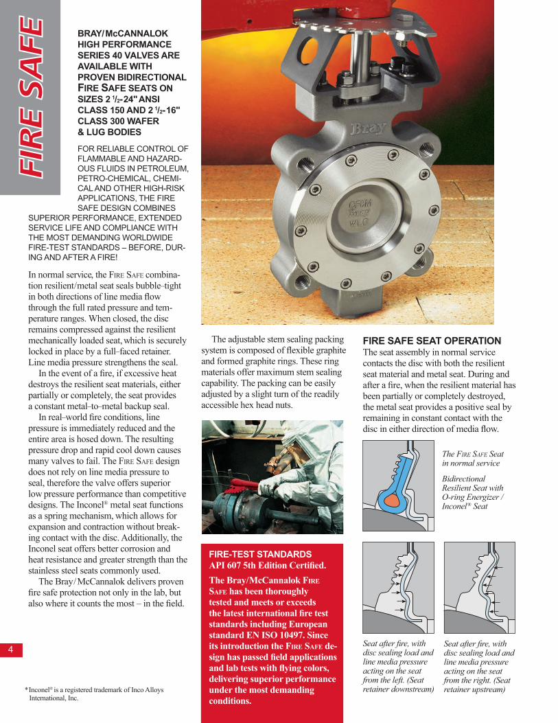
Seat after fire, with disc sealing load and line media pressure acting on the seat from the left. (Seat retainer downstream)
Seat after fire, with disc sealing load and line media pressure acting on the seat from the right. (Seat retainer upstream)
fiRE SafE SEaT opERaTion The seat assembly in normal service contacts the disc with both the resilient seat material and metal seat. During and after a fire, when the resilient material has been partially or completely destroyed, the metal seat provides a positive seal by remaining in constant contact with the disc in either direction of media flow.
The adjustable stem sealing packing system is composed of flexible graphite and formed graphite rings. These ring materials offer maximum stem sealing capability. The packing can be easily adjusted by a slight turn of the readily accessible hex head nuts.
The Fire SaFe Seat in normal service
Bidirectional Resilient Seat with O-ring Energizer / Inconel® Seat
fiRE-TEST STandaRdSAPI 607 5th Edition Certified. The Bray/McCannalok Fire SaFe has been thoroughly tested and meets or exceeds the latest international fire test standards including European standard EN ISO 10497. Since its introduction the Fire SaFe de-sign has passed field applications and lab tests with flying colors, delivering superior performance under the most demanding conditions.
* Inconel® is a registered trademark of Inco Alloys International, Inc.
4

bray/mccannalok Series 40 valves handle a wide range of conditions and media, such as corrosive chemicals, water, gases, acids, alkalies, hydrocarbons plus many other fluids. Bray’s standard valve line has been specifically designed to meet most applications. When applications demand special requirements, bray offers valves and materials that meet these needs. Services and optional materials include:
vacuumStandard Series 40 valves with TFE seats are recommended for vacuum service down to .02 mm Hg absolute pressure, or 20 microns. For vacuum service down to 1 x 10 -3 mm Hg absolute pressure, or 1 micron, specially prepared valves are recommended. Under certain conditions, these valves serve well in the high vacuum range down to 1 x 10⁻⁶ mm Hg absolute pressure.
STEamSeries 40 valves are specifically designed for a wide range of high temperature and high pressure applications including on-off and modulating control of hot water, condensed water or chilled water. The Series 40 valve is rated 150 psi (10.3 bar) saturated steam at 366°F (185°C) for on-off applications. For modulating service, the Series 40 is rated 50 psi at 300°F. Use of the standard RTFE seat is recommended for this service.
dRy chLoRinE – gas or LiquidSpecial materials as well as assembly and testing procedures are applied to assure bubble–tight closure in these critical services.
oXygEnSeries 40 valves for critical gaseous oxygen service are specially prepared, cleaned, inspected, assembled and tested to ensure removal of all burrs, sharp edges, dirt, hydrocarbon oil or grease, and other contaminants. Each valve is individually wrapped and sealed in polyethylene before shipment.
aSh handLing and abRaSivEFor applications where flow velocity and differential pressure are low, RTFE or UHMWPE seats and electroless nickel plated discs are recommended. For applications requiring improved resistance to wear and particles of higher hardness, a Fire SaFe design is recom-mended. SEa WaTER Series 40 valves have been successfully installed in power plants, desalination plants and deep sea drilling projects. Duplex, super duplex and super-austenitic stainless trims can be provided for sea water service. Higher alloy materials are available. cauSTicValve materials must be selected for sufficient corrosion requirements. Stainless steel is recommended for sodium and potassium hydroxide applications. hEaTing, vEnTiLaTion and aiR condiTioning (hvac)Series 40 valves can be used for damping or balancing water flow, main stop valves, block valves, throttling valves, and control of pump suction or discharge.
SouR gaSSelected materials of construction meeting NACE standards (MR-01-75) permit ready application and maximum serviceability in these difficult services.
dEad–End SERvicEBray/McCannalok lug bodies for bidirectional dead– end service are offered as standard in full ANSI Class 150, 300 and 600 ratings.
please consult your bray representative for specific recommendations regarding your requirements.
5
Series 40 valves can be optionally supplied in a number of different seat and body materials, including:• PTFE and UHMWPE seats with resilient energizer.• Fluorosilicone inner O– rings for methylene chloride service.• Fire SaFe graphite/carbon fiber or similar packing for fire safe or high tempera- ture service.• Hastelloy C bodies for hydrogencyanide service.• Nickel Aluminum bronze bodies for marine environments.• Longer stem lengths to accmodate differing cotrol areas.• Alloy 20 trim for sulfuric acid service.• Monel discs for Chlorine service.• Duplex, Superduplex and Super- austenitic stainless trims for salt water services. • Many other materials are also available, please consult the Bray factory.
APPROVALS U.S. COAST GUARDThe Bray/McCannalok High Perfor-mance Valve has been approved by the U.S. Coast Guard and American Bureau of Shipping for category A and P applications. NUCLEAR Bray Series 40 valves have been suc-cessfully used in nuclear power plants in the USA, China and many other countries. There are more Series 40 valves in "N-Stamp" installations than any other HPBV in the world. UL/NSF-61- Potable water. ABSDNV

HG
H
c
B
h
J
e
d
lugBolting
a
f
k
mounting
Øg
k
(=) (=)
l
a B c d e f g h J k l lug Bolting data
Threadsun-2B
No.holes
Series 40
WEighTS Series
41
anSi 150 Series 40 Series 41
**(h=flats)
**(H=Keyway)
**Keyway is applicable on valve sizes 14"-54" Class 150, 10"-48" Class 300, and 8"-30" Class 600.
**
S42 anSi 300 Series 42 Series 43
Dimensions are in inches and weights in lbs.Weights are for Cast Steel bodies, except when noted by *. * Flame cut body weights. Flame Cut Steel and SS bodies vary. Please con-sult factory.
S43
‡
‡C dimension is absolute minimum pipe ID at valve face (without gasket).
Valve Sizeins mm
mounting dataBcd No.
holesholeDia. Bcd
21/2 65 4.75 1.88 2.28 3.81 6.38 4.36 2.76 4 0.38 0.63 0.43 1.25 2.50 0.77 5.88 8 3/4-10 13 15 3 80 5.25 1.88 2.86 4.09 6.63 4.36 2.76 4 0.38 0.63 0.43 1.25 2.50 0.77 6.62 8 3/4-10 16 17 4 100 6.75 2.03 3.72 4.71 7.50 4.36 2.76 4 0.38 0.63 0.43 1.25 2.50 0.75 7.88 8 3/4-10 20 23 5 125 8.25 2.23 4.80 5.13 8.00 5.12 2.76 4 0.38 0.75 0.51 1.25 4.50 0.94 9.25 8 3/4-10 33 39 6 150 8.88 2.42 5.75 6.25 8.75 5.12 4.92 4 0.53 0.87 0.63 1.25 4.50 0.97 10.62 12 3/4-10 40 54 8 200 10.94 2.82 7.56 7.55 10.00 6.12 4.92 4 0.53 1.18 0.87 2.00 4.50 1.10 13.00 12 7/8-9 68 89 10 250 13.26 3.28 9.44 9.36 11.38 6.12 4.92 4 0.53 1.38 .39x.39 2.00 4.50 1.28 15.25 16 1-8 113 144 12 300 15.57 3.62 11.31 10.89 13.50 7.75 4.92 4 0.53 1.38 .39x.39 2.00 6.50 1.40 17.75 16 11/8-8 173 217 14 350 17.90 4.66 11.38 12.50 18.25 10.38 6.50 4 0.81 1.97 .47x.39 2.50 6.50 2.13 20.25 20 11/8-8 328 444 16 400 19.94 5.35 14.31 13.88 21.00 10.38 6.50 4 0.81 2.50 .62x.62 4.00 6.50 2.50 22.50 20 11/4-8 455 592 18 450 22.00 5.98 15.00 15.43 21.00 15.38 10.00 8 0.67 2.50 .62x.62 4.00 11.75 2.65 24.75 24 11/4-8 605 856 20 500 24.10 6.34 16.50 16.80 22.25 15.38 10.00 8 0.67 3.00 .75x.75 4.00 11.75 2.90 27.00 24 11/4-8 780 1050 24 600 28.88 7.15 20.68 19.80 26.25 19.50 11.73 8 0.81 3.50 .88x.62 5.25 13.50 3.40 32.00 24 11/2-8 1260 1720 30 750 35.12 8.98 26.81 23.40 32.25 24.00 14.02 8 1.25 4.50 1.0x.75 5.25 16.00 4.38 39.25 28 13/4-8 2260 3010 36 900 42.00 10.67 33.13 27.12 36.25 24.00 14.02 8 1.25 5.00 1.25x.88 6.00 16.00 5.23 46.00 32 2-8 3320 4400 42 1050 50.75 11.50 38.88 29.25 40.50 26.00 15.98 8 1.50 6.00 1.5x1.0 6.50 18.70 5.13 47.50 32 15/8-8 5000* 4700 48 1200 57.75 12.50 45.75 33.16 44.75 29.00 19.02 12 1.50 7.00 1.75x.1.5 7.50 22.00 5.50 54.00 32 17/8-8 —* 7000
S44 anSi 600 Series 44 Series 45 S45 3 80 5.78 2.22 2.75 5.71 7.00 5.12 2.76 4 0.38 0.75 0.51 1.25 4.50 0.90 6.62 8 3/4-10 24* 31* 4 100 7.00 2.77 3.56 7.04 8.50 5.12 4.92 4 0.53 0.87 0.63 1.25 4.50 1.15 8.50 8 7/8-9 41* 58‡ 6 150 9.75 3.34 5.38 8.57 9.75 6.12 4.92 4 0.53 1.18 0.87 2.00 4.50 1.50 11.50 12 1-8 79* 119* 8 200 11.80 4.23 6.88 10.80 12.25 7.75 6.50 4 0.81 1.38 .39x.39 2.00 6.50 1.90 13.75 12 11/8-8 155* 227* 10 250 14.09 4.82 8.50 14.62 17.00 10.38 6.50 4 0.81 1.97 .47x.39 2.50 6.50 2.15 17.00 16 11/4-8 280* 400* 12 300 16.47 5.51 10.12 15.72 18.25 10.38 6.50 4 0.81 1.97 .47x.39 2.50 6.50 2.53 19.25 20 11/4-8 386* 547* 14 350 18.03 6.09 10.88 17.48 19.75 15.38 10.00 8 0.67 2.50 .62x.62 4.00 11.75 2.90 20.75 20 13/8-8 549* 750* 16 400 20.38 7.00 12.62 19.41 21.75 15.38 10.00 8 0.67 3.00 .75x.75 4.00 11.75 3.44 23.75 20 11/2-8 752* 1100* 18 450 23.15 7.75 14.60 21.05 23.75 19.50 11.73 8 0.81 3.50 .88x.62 5.25 13.50 3.60 25.75 20 15/8-8 1090* 1470* 20 500 25.15 8.50 16.37 23.21 25.75 19.50 11.73 8 0.81 4.00 1.0x.75 5.25 13.50 3.88 28.50 24 15/8-8 1360* 1850* 24 600 29.38 9.13 19.87 27.71 31.00 24.00 14.02 8 1.25 5.00 1.25x.88 6.00 16.00 3.94 33.00 24 17/8-8 2160* 2900* 30 750 36.00 11.25 26.50 31.50 36.00 26.00 15.98 8 1.50 6.00 1.5x1.0 6.50 18.70 5.00 40.25 28 2-8 3500* 4700*
6
21/2 65 4.75 1.88 2.28 3.81 6.38 4.36 2.76 4 0.38 0.63 0.43 1.25 2.50 0.77 5.50 4 5/8-11 13 14 3 80 5.25 1.88 2.86 4.09 6.63 4.36 2.76 4 0.38 0.63 0.43 1.25 2.50 0.77 6.00 4 5/8-11 16 15 4 100 6.75 2.03 3.72 4.71 7.50 4.36 2.76 4 0.38 0.63 0.43 1.25 2.50 0.75 7.50 8 5/8-11 20 23 5 125 7.50 2.23 4.80 5.07 7.50 5.12 2.76 4 0.38 0.75 0.51 1.25 4.50 0.94 8.50 8 3/4-10 26 34 6 150 8.62 2.23 5.88 5.57 8.00 5.12 2.76 4 0.38 0.75 0.51 1.25 4.50 0.94 9.50 8 3/4-10 33 47 8 200 10.75 2.40 7.80 6.94 9.50 5.12 4.92 4 0.53 0.87 0.63 1.25 4.50 0.94 11.75 8 3/4-10 46 54 10 250 13.06 2.75 9.78 8.56 10.75 6.12 4.92 4 0.53 1.18 0.87 2.00 4.50 1.07 14.25 12 7/8-9 79 94 12 300 15.50 3.08 11.74 10.18 12.25 6.12 4.92 4 0.53 1.18 0.87 2.00 4.50 1.13 17.00 12 7/8-9 123 136 14 350 17.50 3.73 12.90 11.95 14.50 7.75 4.92 4 0.53 1.38 .39x.39 2.00 6.50 1.42 18.75 12 1-8 208 227 16 400 19.81 4.11 14.68 12.94 17.75 10.38 6.50 4 0.81 1.97 .47x.39 2.50 6.50 1.66 21.25 16 1-8 313 345 18 450 21.41 4.61 16.60 14.15 20.00 10.38 6.50 4 0.81 1.97 .47x.39 2.50 6.50 1.86 22.75 16 11/8-8 402 442 20 500 23.68 5.03 18.50 15.26 22.75 10.38 6.50 4 0.81 2.50 .62x.62 4.00 6.50 2.06 25.00 20 11/8-8 527 604 24 600 28.00 6.00 22.50 18.21 25.00 15.38 10.00 8 0.67 3.00 .75x.75 4.00 11.75 2.44 29.50 20 11/4-8 813 930 26 650 29.50 6.50 22.36 19.23 25.00 15.38 10.00 8 0.67 3.00 .75x.75 4.00 11.75 2.81 31.75 24 11/4-8 970* 1280* 28 700 32.41 6.50 26.47 20.54 26.75 15.38 10.00 8 0.67 3.00 .75x.75 4.00 11.75 2.81 34.00 28 11/4-8 1115 1300 30 750 34.50 7.50 28.31 21.36 28.75 19.50 11.73 8 0.81 3.50 .88x.62 5.25 13.50 3.10 36.00 28 11/4-8 1475 1740 32 800 37.62 7.50 30.19 22.36 30.00 19.50 11.73 8 0.81 3.50 .88x.62 5.25 13.50 3.22 38.50 28 11/2-8 1650* 2060* 34 850 39.62 7.75 30.13 23.86 30.00 19.50 11.73 8 0.81 3.50 .88x.62 5.25 13.50 3.35 40.50 32 11/2-8 1890* 2340* 36 900 40.68 8.26 34.00 25.27 33.00 19.50 11.73 8 0.81 3.50 .88x.62 5.25 13.50 3.63 42.75 32 11/2-8 1960 2600 40 1000 51.00 9.50 36.99 27.25 37.00 19.50 11.73 8 0.81 4.50 1.0x.75 5.25 13.50 4.38 47.25 36 11/2-8 3850* 3950* 42 1050 53.31 9.50 39.05 29.37 38.00 19.50 11.73 8 0.81 4.50 1.0x.75 5.25 13.50 4.38 49.50 36 11/2-8 4250* 4300 48 1200 54.00 10.00 46.09 33.12 42.13 24.00 14.02 8 1.25 5.00 1.25x.88 6.00 16.00 4.50 56.00 44 11/2-8 4610* 5680* 54 1400 66.38 10.75 52.45 35.65 45.50 24.00 14.02 8 1.25 6.00 1.5x1.0 6.50 16.00 4.75 62.75 44 13/4-8 7100* 7210* 60 1500 73.00 12.50 57.07 39.44 50.75 26.00 15.98 8 1.50 7.00 1.75x1.50 7.50 18.70 4.75 69.25 52 13/4-8 —* 9360*

anSi 150 Series 40 / 41
anSi 300 Series 42 / 43
anSi 600 Series 44 / 45
Stainless Steel Bodies RTFE Seats
Stainless Steel Bodies PTFE Seats
0 100 200 250
0 100 200 300 400 500-20
600
800
1000
1200
1400
1600
Temperature °c
Temperature °f
pres
sure
Bar
pres
sure
psi
g
400
20020
40
60
80
100
0 100 200 250
0 100 200 300 400 500-20
300
400
500
600
700
800
Temperature °c
Temperature °f
pres
sure
Bar
pres
sure
psi
g
200
10010
20
30
40
50
0 100 200 250
0 100 200 300 400 500-20
50
100
150
200
250
300
350
5
10
15
20
Temperature °c
Temperature °f
pres
sure
Bar
pres
sure
psi
g
ins mm 90° 80° 70° 60° 50° 40° 30° 20° 10° Valve Size Disc Position (degrees) anSi 150 Series 40 / 41
Cv is defined as the volume of water in U.S.G.P.M. that will flow through a given restriction or valve opening with a pressure drop of one (1) p.s.i. at room temperature. Recommended control angles are between 25°–70° open. Preferred angle for control valve sizing is 60°–65° open.
Carbon Steel Bodies RTFE Seats
Carbon Steel Bodies PTFE Seats
anSi 300 Series 42 / 43
anSi 600 Series 44 / 45
cv
vaLu
ES–v
aLv
E Si
Zin
g c
oEf
fic
iEn
T
pRES
SuR
E / T
EmpE
RaT
uR
E 21/2 65 160 136 100 78 50 30 16 8 3 3 80 185 178 155 123 87 56 32 14 4.8 4 100 375 365 315 250 175 115 63 31 10 5 125 790 675 500 360 238 146 78 41 16 6 150 1000 875 710 530 370 240 138 79 26 8 200 2000 1720 1360 950 630 405 240 121 47 10 250 2650 2250 1740 1200 780 510 295 150 61 12 300 4000 3400 2500 1690 1100 710 430 220 92 14 350 4100 3500 2600 1770 1200 830 490 240 100 16 400 7800 6540 4550 2970 1840 1160 730 420 180 18 450 9500 8000 6170 4530 3110 1970 1080 440 94 20 500 11000 9570 7300 5400 3720 2330 1250 530 110 24 600 18000 15100 11400 8570 5920 3700 2000 830 180 30 750 29000 24400 18900 13700 8500 6000 3230 1330 290 36 900 45000 38100 29200 21000 14800 9100 4660 1730 380 42 1050 60000 54000 42000 30000 19000 13000 7500 2600 450 48 1200 83000 74000 58000 41000 26000 17000 10000 4400 800
3 80 165 158 135 103 67 46 12 8 3 4 100 300 270 210 150 95 70 45 30 5 6 150 850 765 600 425 270 200 130 70 15 8 200 1500 1350 1050 750 480 345 209 78 20 10 250 2200 1970 1540 1100 700 500 300 140 40 12 300 3100 2790 2170 1550 1000 680 400 190 55 14 350 3900 3300 2400 1570 1100 730 420 200 70 16 400 5000 4200 2900 1900 1200 800 500 250 95 18 450 6000 5000 3900 2800 1900 1200 660 290 130 20 500 8000 6900 5300 3900 2700 1700 950 400 143 24 600 11000 9300 7000 5200 3600 2250 1200 500 180 30 750 15000 13000 10000 8400 5100 2800 1650 600 200
7
Note: Refer to Bray Technical Bulletin No.1168 for additional information on Pressure/Temperature Curves.
21/2 65 160 136 100 78 50 30 16 8 3 3 80 185 178 155 123 87 56 32 14 4.8 4 100 375 365 315 250 175 115 63 31 10 5 125 790 675 500 360 238 146 78 41 16 6 150 1350 1070 750 510 330 218 140 81 35 8 200 2800 2230 1590 1060 685 456 280 165 65 10 250 4300 3450 2430 1630 1050 700 450 250 100 12 300 6650 5330 3750 2530 1630 1080 700 390 155 14 350 7650 6100 4300 2900 1890 1250 810 450 175 16 400 9800 7860 5510 3700 2420 1530 1020 580 230 18 450 10500 9100 6960 5100 3520 2220 1180 500 170 20 500 13500 11700 8800 6500 4500 2820 1530 640 200 24 600 20000 17100 12800 9570 6640 3880 2200 920 240 26 650 20000 17100 12800 9570 6640 3880 2200 920 240 28 700 28000 23900 18200 13500 9300 5700 3100 1300 290 30 750 32000 27300 20900 15500 10700 6700 3600 1510 320 32 800 34000 29100 22300 16500 11400 7150 3850 1610 340 34 850 34000 29100 22300 16500 11400 7150 3850 1610 340 36 900 48500 41100 31700 23200 16400 10200 5430 2260 480 40 1000 62000 55200 44000 33300 23800 15200 8600 3520 670 42 1050 65000 58000 46100 35000 25000 16000 9000 3700 700 48 1200 91000 80900 63700 43600 29100 20000 11000 4600 920 54 1400 125000 111000 87500 60000 40000 27500 15000 6000 1200 60 1500 160000 140000 105000 75000 50000 31000 17000 7000 1400

anSi 150 Series 40 / 41 Fire SafeValve Size
System Pressure ∆ P (PSIG)Less than 150 150 – 200 200 – 250 250 – 285
RetainerUpstream
RetainerDownstreamins Retainer
UpstreamRetainer
DownstreamRetainerUpstream
RetainerDownstream
RetainerUpstream
RetainerDownstream
2 1/2 680 720 775 860 3 750 800 855 950 4 850 900 1080 1200 5 1420 1500 2070 2300 6 2000 2100 2610 2900 8 3000 3150 3870 4300 10 6900 7300 9180 10200 12 10450 11000 13200 14700
900 1200 1000 1450 1580 2100 1900 2700 3450 4600 4100 5800 7600 10100 9800 14000 13500 18000 16800 24000 19500 26000 21000 30000
2 1/2 170 200 190 240 210 280 215 300 3 185 220 210 260 225 300 230 320 4 275 320 300 370 315 420 320 460 5 550 650 640 800 705 940 730 1040 6 690 810 770 960 825 1100 840 1200 8 1280 1500 1400 1700 1500 1950 1570 2100 10 2400 2800 2640 3300 2820 3760 2870 4100 12 3500 4100 4000 5000 4400 5900 4550 6500
Valve Size
System Pressure ∆ P (PSIG)Less than 150 150 – 200 200 – 250 250 – 285
RetainerUpstream
RetainerDownstreamins Retainer
UpstreamRetainer
DownstreamRetainerUpstream
RetainerDownstream
RetainerUpstream
RetainerDownstream
2 1/2 680 720 690 770 700 810 710 840 3 750 800 760 830 770 870 780 900 4 850 900 880 980 890 1050 910 1100 5 1420 1500 1470 1630 1500 1750 1600 1850 6 1660 1750 1690 1880 1800 2000 1900 2100 8 2600 2800 2690 2950 2750 3100 2860 3200 10 3900 4200 4100 4530 4250 4860 4400 5100 12 6500 6900 6600 7350 6700 7790 6900 8100
2 1/2 170 200 290 360 380 510 470 670 3 185 220 310 380 400 530 490 690 4 270 320 420 530 550 730 700 1000 5 550 650 1000 1250 1390 1850 1800 2550 6 850 1000 1320 1650 1720 2300 2100 3000 8 1580 1850 2480 3100 3230 4300 3700 5300 10 2800 3300 4400 5500 5700 7600 7000 10000 12 4250 5000 6640 8300 8630 11500 10500 15000
Valve Size
anSi 300 Series 42 / 43 StandardSystem Pressure ∆ P (PSIG)
Less than 150 150 – 350 350 – 550 550 – 740RetainerUpstream
RetainerDownstreamins Retainer
UpstreamRetainer
DownstreamRetainerUpstream
RetainerDownstream
RetainerUpstream
RetainerDownstream
Valve Size
anSi 300 Series 42 / 43 Fire SafeSystem Pressure ∆ P (PSIG)
Less than 150 150 – 350RetainerUpstream
RetainerDownstreamins Retainer
UpstreamRetainer
Downstream
350 – 550 550 – 740RetainerUpstream
RetainerDownstream
RetainerUpstream
RetainerDownstream
3 400 480 700 870 4 850 960 1280 1600 6 1450 1700 2560 3200 8 3500 4100 5760 7200 10 7100 8300 9600 12000 12 10100 11800 11200 14000
Valve Size
anSi 600 Series 44 / 45
Less than 150 150 – 600RetainerUpstream
RetainerDownstreamins Retainer
UpstreamRetainer
Downstream
System Pressure ∆ P (PSIG)600 – 1050 1050 – 1480
RetainerUpstream
RetainerDownstream
RetainerUpstream
RetainerDownstream
8
anSi 150 Series 40 / 41 Standard The values in the following Torque Charts for standard valves are for normal, wet me-dia applications. Note that seating/unseating torque is always lower with the seat retainer installed upstream. Please consult Bray Technical Bulletin No. 1146 for discus-sion on service torque classes applicable to standard valves. If the media is lubricious, such as oil, the values in the Torque Charts should be multiplied by 0.9. If the media is abrasive or dry and thus a severe application, the values in charts should be multiplied by 1.3. For firesafevalves, the operating torque should be taken directly from the charts, with due consideration for the location of the seat retainer. No reduction or multiplication factors should be used to determine torque of firesafe valves. These torque figures are seating and unseating torques. Dynamic torques should also be determined in the event dynamic torques are greater than the seating/unseat-ing torques. Refer to Bray Technical Bulletin No. 1172 for dynamic torques.
SEaTing/unSEaTing ToRquES (Lb-inS)
860 1010 880 1100 935 1100 960 1200 1275 1500 1360 1700 2635 3100 2880 3600 3150 3700 3440 4300 4675 5500 4960 6200 11050 13000 12000 15000 15640 18400 16800 21000
**For torque ratings on valves 14 inches and above, please consult TB-1146 or a Bray representative.
14
13
12
3
4
11
7
8
9
6
6
18
19
2
5
5
15
16
17
1
10
2021
22
Exploded View Series 40
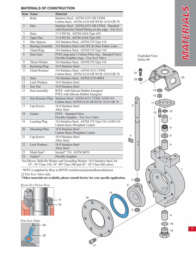
Item Name Material 1 Body Stainless Steel, ASTM A351 GR CF8M Carbon Steel, ASTM A216 GR WCB /A516 GR 70 2 Disc Stainless Steel, ASTM A351 GR CF8M – Standard with Electroless Nickel Plating on disc edge – Fire SaFe 3 Stem 17-4 PH SS, ASTM A564-Type 630 4 Taper Pins 17-4 PH SS, ASTM A564-Type 630 5 Disc Spacers 316 Stainless Steel, ASTM 276 Type 316 6 Bearing Assembly 316 Stainless Steel with TFE & Glass Fabric Liner 7 Gland Ring 316 Stainless Steel, ASTM 276 Type 316 8 Stem Seal PTFE rings plus 1 Carbon Fiber ring – Standard Valve Flexible Graphite rings – Fire SaFe Valve 9 Thrust Washer 316 Stainless Steel, ASTM 276 Type 316 10 Retaining Ring 18-8 Stainless Steel 11 Gland Retainer 316 Stainless Steel, ASTM A351 CF8M Carbon Steel, ASTM A216 GR WCB /A516 GR 7012 Stud 316 Stainless Steel, ASTM A193-B8M13 Lock Washers 18-8 Stainless Steel 14 Hex Nut 18-8 Stainless Steel 15 Seat Assembly RTFE^ with Silicone Rubber Energizer PTFE with Silicone Rubber Energizer16 Seat Retainer Plate Stainless Steel, ASTM A351 CF8M /A240-316 Carbon Steel, ASTM A216 GR WCB /A516 GR 7017 Cap Screws 18-8 Stainless Steel Alloy Steel18 Gasket PTFE – Standard Valve Flexible Graphite – Fire SaFe Valve19 Locating Plug 316 Stainless Steel, ASTM 276 Type 316/A240-316 Carbon Steel, Phosphate Coated20 Mounting Plate 18-8 Stainless Steel Carbon Steel, Phosphate Coated21 Cap Screws 18-8 Stainless Steel Alloy Steel22 Lock Washers 18-8 Stainless Steel Alloy Steel 23 Metal Seat‡‡ Inconel® 718, ASTM B67024 Gasket‡‡ Flexible GraphiteNot Shown: Bellville Washer and Grounding Washer: 18-8 Stainless Steel, for 14"– 54" Class 150, 14"–48" Class 300 and 10"– 30" Class 600 valves
^ RTFE is supplied by Bray as RPTFE (reinforced polytetrafluoroethylene).‡‡ Fire SaFe Valve only.*Other materials are available, please consult factory for your specific application.
maTERiaLS of conSTRucTion
9
Blow-out ProoF Stem
24
23
Fire SaFe Valve
1110

Bray® is a registered trademark of BRAy INTERNATIoNAL, Inc. © 2007 Bray International. All rights reserved. B-1023-EN 9/08
All statements, technical information, and recom-mendations in this bulletin are for general use only. Consult Bray representatives or factory for the specific requirements and material selection for your intended application. The right to change or modify product design or product without prior notice is reserved.
disTriBuTor
diREcT mounTing of compacT, high ToRquE bRay pnEumaTic and ELEcTRic acTuaToRS pRo-vidE LoW coST auTomaTion foR ON-OFF AND CONTROL SERVICES. The Series 40 valves can be automated inexpensively with Bray’s pneumatic and electric actuators. These actuators fully complement the Bray/McCannalok and directly mount without the need for large brackets or adapters. Bray has designed the most advanced, highest quality line of actuators and Brayline accessories available today.
At left, a Series 92 Pneumatic Actuator with a Series 52 Valve Status Monitor are mounted to a 3" Series 40 Valve. At right, a Series 70 Electric Actuator is shown mounted to a 3" Series 40 Valve.
plug SERIES 40 globe SERIES 40 gate SERIES 40
in addiTion To ThE EXcELLEnT fEaTuRES of ThE SERiES 40, ThiS high pERfoRmancE buTTERfLy vaLvE offERS SupERioR advanTagES ovER OTHER VALVES.
The cost savings of installation and maintenance are substantial. The torque requirements of the High Performance Series 40 Butterfly Valve are also significantly lower. For example, an 8" Series 40 Class 150 valve weighs 45 lbs. and has a maximum torque of 1,500 in/lbs. Comparable plug valves weigh 319 lbs. with 12,500 in/lbs. of torque, and ball valves weigh 158 lbs. with 6,400
in/lbs. of torque. A gate valve with a comparable rating weighs 310 lbs. and requires a linear unit for actuation. Therefore, the Series 40 Butterfly Valve requires a much smaller actuator than other valves. Economy, efficiency and proven superior performance establish the Bray/McCannalok as the premier solution for demanding high pres-sure applications.
When matched against comparably rated plug, globe, gate, ball and diaphragm valves, the reduced weight and space requirements of the Series 40 is readily apparent.
CONTROLSA Division of BRAY INTERNATIONAL, Inc.13333 Westland East Blvd. Houston, Texas 77041281.894.5454 FAX 281.894.9499 www.bray.com