Embed Size (px)
Citation preview
HIGH-PERFORMANCE ANCHOR W-HAZ/A4
Benefits:• Europ
288
W-HAZ/A4
Description Authority/ Laboratory
Guideline for Assessment
No./date of issue
European Technical Approval
DIBt, Berlin ETAG 001-T2 ETA-02/0031 / 2013-03-26
Fire resistance DIBt, Berlin TR 020 ETA-02/0031 / 2013-03-26
Sprinkler systems VdS VdS CEA 4001: 2010-11 (04) 2012-03-27
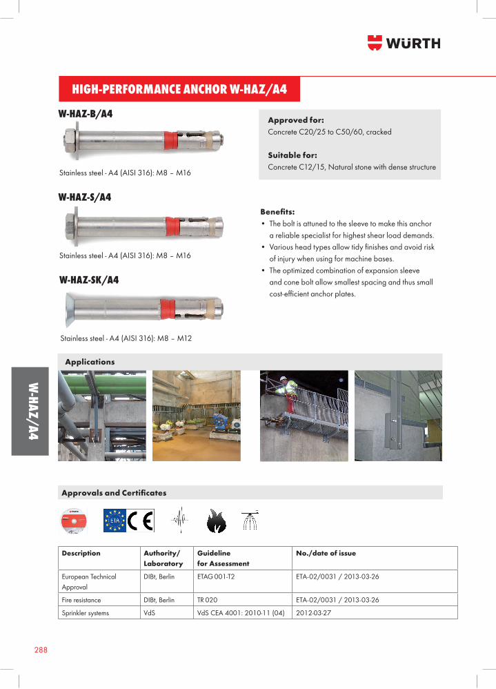
Stainless steel - A4 (AISI 316): M8 – M16
Approved for: Concrete C20/25 to C50/60, cracked
Suitable for:Concrete C12/15, Natural stone with dense structure
Benefits: • The bolt is attuned to the sleeve to make this anchor a reliable specialist for highest shear load demands.• Variousheadtypesallowtidyfinishesandavoidrisk of injury when using for machine bases.• The optimized combination of expansion sleeve and cone bolt allow smallest spacing and thus small cost-efficientanchorplates.
Approvals and Certificates
W-HAZ-B/A4
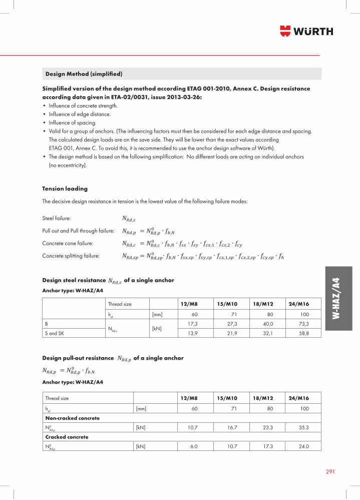
Applications
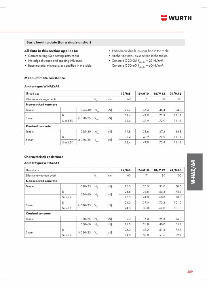
Stainless steel - A4 (AISI 316): M8 – M16
W-HAZ-S/A4
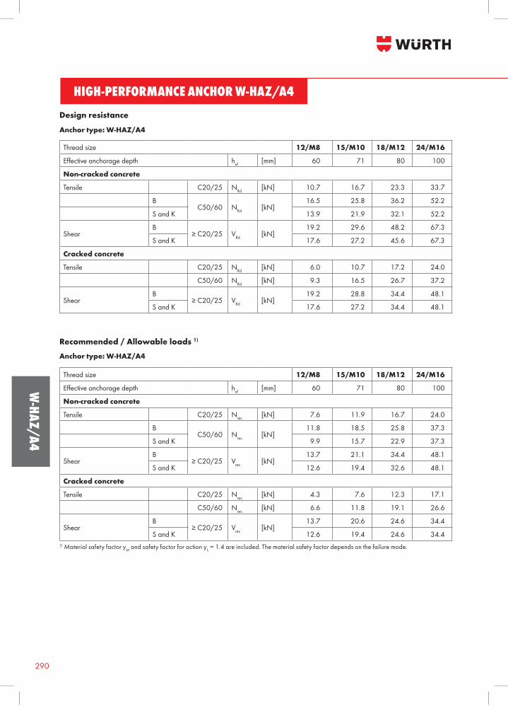
Stainless steel - A4 (AISI 316): M8 – M12
W-HAZ-SK/A4
289
W-H
AZ/A
4
Basic loading data (for a single anchor)
Mean ultimate resistance
All data in this section applies to: • Correct setting (See setting instruction).• Noedgedistanceandspacinginfluence.• Basematerialthickness,asspecifiedinthetable.
• Embedmentdepth,asspecifiedinthetable.• Anchormaterial,asspecifiedinthetables.• Concrete C 20/25, fck,cube = 25 N/mm², Concrete C 50/60, fck,cube = 60 N/mm².
Anchor type: W-HAZ/A4
Thread size 12/M8 15/M10 18/M12 24/M16
Effectiveanchoragedepth hef [mm] 60 71 80 100
Non-cracked concrete
Tensile C25/30 Nu,m [kN] 23.7 36.4 46.4 84.0
ShearB
≥C20/25 Vu,m [kN]32.4 47.9 72.9 111.1
S and SK 32.4 47.9 72.9 111.1
Cracked concrete
Tensile C25/30 Nu,m [kN] 19.8 31.6 37.2 68.8
ShearB
≥C20/25 Vu,m [kN]32.4 47.9 72.9 111.1
S and SK 32.4 47.9 72.9 111.1
Characteristic resistance
Anchor type: W-HAZ/A4
Thread size 12/M8 15/M10 18/M12 24/M16
Effectiveanchoragedepth hef [mm] 60 71 80 100
Non-cracked concrete
Tensile C20/25 NRk [kN] 16.0 25.0 35.0 50.5
BC50/60 NRk [kN]
24.8 38.8 54.3 78.3
S and K 26.0 41.0 60.0 78.3
ShearB
≥C20/25 VRk [kN]24.0 37.0 72.3 101.0
S and K 24.0 37.0 62.0 101.0
Cracked concrete
Tensile C20/25 NRk [kN] 9.0 16.0 25.8 36.0
C50/60 NRk [kN] 14.0 24.8 40.0 55.8
ShearB
≥C20/25 VRk [kN]24.0 43.2 51.6 72.1
S and K 24.0 37.0 51.6 72.1
HIGH-PERFORMANCE ANCHOR W-HAZ/A4
Benefits:• Europ
290
W-HAZ/A4
Design resistance
Anchor type: W-HAZ/A4
Thread size 12/M8 15/M10 18/M12 24/M16
Effectiveanchoragedepth hef [mm] 60 71 80 100
Non-cracked concrete
Tensile C20/25 NRd [kN] 10.7 16.7 23.3 33.7
BC50/60 NRd [kN]
16.5 25.8 36.2 52.2
S and K 13.9 21.9 32.1 52.2
ShearB
≥C20/25 VRd [kN]19.2 29.6 48.2 67.3
S and K 17.6 27.2 45.6 67.3
Cracked concrete
Tensile C20/25 NRd [kN] 6.0 10.7 17.2 24.0
C50/60 NRd [kN] 9.3 16.5 26.7 37.2
ShearB
≥C20/25 VRd [kN]19.2 28.8 34.4 48.1
S and K 17.6 27.2 34.4 48.1
Recommended / Allowable loads 1)
1) Material safety factor yM and safety factor for action y L = 1.4 are included. The material safety factor depends on the failure mode.
Thread size 12/M8 15/M10 18/M12 24/M16
Effectiveanchoragedepth hef [mm] 60 71 80 100
Non-cracked concrete
Tensile C20/25 Nrec [kN] 7.6 11.9 16.7 24.0
BC50/60 Nrec [kN]
11.8 18.5 25.8 37.3
S and K 9.9 15.7 22.9 37.3
ShearB
≥C20/25 Vrec [kN]13.7 21.1 34.4 48.1
S and K 12.6 19.4 32.6 48.1
Cracked concrete
Tensile C20/25 Nrec [kN] 4.3 7.6 12.3 17.1
C50/60 Nrec [kN] 6.6 11.8 19.1 26.6
ShearB
≥C20/25 Vrec [kN]13.7 20.6 24.6 34.4
S and K 12.6 19.4 24.6 34.4
Anchor type: W-HAZ/A4
291
W-H
AZ/A
4
Design Method (simplified)
Simplified version of the design method according ETAG 001-2010, Annex C. Design resistance according data given in ETA-02/0031, issue 2013-03-26:• Influenceofconcretestrength.• Influenceofedgedistance.• Influenceofspacing.• Validforagroupofanchors.(Theinfluencingfactorsmustthenbeconsideredforeachedgedistanceandspacing. The calculated design loads are on the save side. They will be lower than the exact values according ETAG 001, Annex C. To avoid this, it is recommended to use the anchor design software of Würth).• Thedesignmethodisbasedonthefollowingsimplification:Nodifferentloadsareactingonindividualanchors (no eccentricity).
Design steel resistance of a single anchor
The decisive design resistance in tension is the lowest value of the following failure modes:
Steel failure:
Pull out and Pull through failure:
Concrete cone failure:
Concrete splitting failure:
Tension loading
Anchor type: W-HAZ/A4
Thread size 12/M8 15/M10 18/M12 24/M16
hef [mm] 60 71 80 100
BNRd,s [kN]
17,3 27,3 40,0 73,3
S and SK 13,9 21,9 32,1 58,8
Design pull-out resistance of a single anchor
Anchor type: W-HAZ/A4
Thread size 12/M8 15/M10 18/M12 24/M16
hef [mm] 60 71 80 100
Non-cracked concrete
N0Rd,p [kN] 10.7 16.7 23.3 35.3
Cracked concrete
N0Rd,p [kN] 6.0 10.7 17.3 24.0
HIGH-PERFORMANCE ANCHOR W-HAZ/A4
Benefits:• Europ
292
W-HAZ/A4
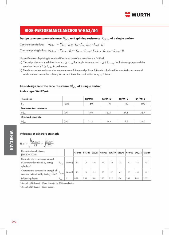
Design concrete cone resistance and splitting resistance of a single anchor
Concrete cone failure:
Concrete splitting failure:
Noverificationofsplittingisrequiredifatleastoneoftheconditionsisfulfilled:a) The edge distance in all directions is for single fasteners and for fastener groups and the member depth is in both cases.b) The characteristic resistance for concrete cone failure and pull-out failure is calculated for cracked concrete and reinforcement resists the splitting forces and limits the crack width to .
Basic design concrete cone resistance of a single anchor
Anchor type: W-HAZ/A4
Thread size 12/M8 15/M10 18/M12 24/M16
hef [mm] 60 71 80 100
Non-cracked concrete
N0Rd,c [kN] 15.6 20.1 24.1 33.7
Cracked concrete
N0Rd,c [kN] 11.2 14.4 17.2 24.0
Influence of concrete strength
1) strength at 28days of 150mm diameter by 300mm cylinders.2) strength at 28days of 150mm cubes.
Concrete strength classes(EN 206:2000)
C12/15 C16/20 C20/25 C25/30 C30/37 C35/45 C40/50 C45/55 C50/60
Characteristic compressive strength of concrete determined by testing cylinders1)
fck,cyl[N/mm2] 12 16 20 25 30 35 40 45 50
Characteristic compressive strength of concrete determined by testing cube2)
fck,cube[N/mm2] 15 20 25 30 37 45 50 55 60
Influencingfactor fb,N[-] 0.77 0.89 1.00 1.10 1.22 1.34 1.41 1.48 1.55
293
W-H
AZ/A
4
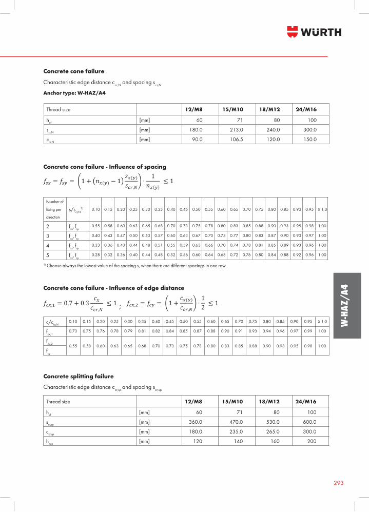
Concrete cone failure
Characteristic edge distance ccr,N and spacing scr,N
Anchor type: W-HAZ/A4
Thread size 12/M8 15/M10 18/M12 24/M16
hef [mm] 60 71 80 100
scr,N [mm] 180.0 213.0 240.0 300.0
ccr,N [mm] 90.0 106.5 120.0 150.0
Concrete cone failure - Influence of spacing
Number of
fixingper
direction
s/scr,N1) 0.10 0.15 0.20 0.25 0.30 0.35 0.40 0.45 0.50 0.55 0.60 0.65 0.70 0.75 0.80 0.85 0.90 0.95 ≥1.0
2 fsx, fsy0.55 0.58 0.60 0.63 0.65 0.68 0.70 0.73 0.75 0.78 0.80 0.83 0.85 0.88 0.90 0.93 0.95 0.98 1.00
3 fsx, fsy0.40 0.43 0.47 0.50 0.53 0.57 0.60 0.63 0.67 0.70 0.73 0.77 0.80 0.83 0.87 0.90 0.93 0.97 1.00
4 fsx, fsy0.33 0.36 0.40 0.44 0.48 0.51 0.55 0.59 0.63 0.66 0.70 0.74 0.78 0.81 0.85 0.89 0.93 0.96 1.00
5 fsx, fsy0.28 0.32 0.36 0.40 0.44 0.48 0.52 0.56 0.60 0.64 0.68 0.72 0.76 0.80 0.84 0.88 0.92 0.96 1.00
1)Choosealwaysthelowestvalueofthespacings,whentherearedifferentspacingsinonerow.
Concrete cone failure - Influence of edge distance
c/ccr,N
0.10 0.15 0.20 0.25 0.30 0.35 0.40 0.45 0.50 0.55 0.60 0.65 0.70 0.75 0.80 0.85 0.90 0.95 ≥1.0
fcx,10.73 0.75 0.76 0.78 0.79 0.81 0.82 0.84 0.85 0.87 0.88 0.90 0.91 0.93 0.94 0.96 0.97 0.99 1.00
fcx,2 0.55 0.58 0.60 0.63 0.65 0.68 0.70 0.73 0.75 0.78 0.80 0.83 0.85 0.88 0.90 0.93 0.95 0.98 1.00fcy
Concrete splitting failure
Characteristic edge distance ccr,sp and spacing scr,sp
Thread size 12/M8 15/M10 18/M12 24/M16
hef [mm] 60 71 80 100
scr,sp [mm] 360.0 470.0 530.0 600.0
ccr,sp [mm] 180.0 235.0 265.0 300.0
hmin [mm] 120 140 160 200
;
HIGH-PERFORMANCE ANCHOR W-HAZ/A4
Benefits:• Europ
294
W-HAZ/A4
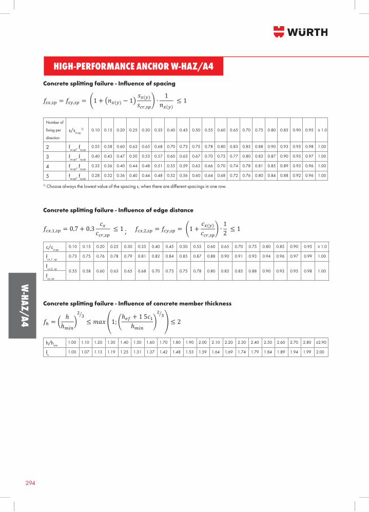
Concrete splitting failure - Influence of spacing
Number of
fixingper
direction
s/scr,sp1) 0.10 0.15 0.20 0.25 0.30 0.35 0.40 0.45 0.50 0.55 0.60 0.65 0.70 0.75 0.80 0.85 0.90 0.95 ≥1.0
2 fsx,sp, fsy,sp0.55 0.58 0.60 0.63 0.65 0.68 0.70 0.73 0.75 0.78 0.80 0.83 0.85 0.88 0.90 0.93 0.95 0.98 1.00
3 fsx,sp, fsy,sp0.40 0.43 0.47 0.50 0.53 0.57 0.60 0.63 0.67 0.70 0.73 0.77 0.80 0.83 0.87 0.90 0.93 0.97 1.00
4 fsx,sp, fsy,sp0.33 0.36 0.40 0.44 0.48 0.51 0.55 0.59 0.63 0.66 0.70 0.74 0.78 0.81 0.85 0.89 0.93 0.96 1.00
5 fsx,sp, fsy,sp0.28 0.32 0.36 0.40 0.44 0.48 0.52 0.56 0.60 0.64 0.68 0.72 0.76 0.80 0.84 0.88 0.92 0.96 1.00
1)Choosealwaysthelowestvalueofthespacings,whentherearedifferentspacingsinonerow.
Concrete splitting failure - Influence of edge distance
Concrete splitting failure - Influence of concrete member thickness
h/hmin1.00 1.10 1.20 1.30 1.40 1.50 1.60 1.70 1.80 1.90 2.00 2.10 2.20 2.30 2.40 2.50 2.60 2.70 2.80 ≥2.90
fh 1.00 1.07 1.13 1.19 1.25 1.31 1.37 1.42 1.48 1.53 1.59 1.64 1.69 1.74 1.79 1.84 1.89 1.94 1.99 2.00
c/ccr,sp 0.10 0.15 0.20 0.25 0.30 0.35 0.40 0.45 0.50 0.55 0.60 0.65 0.70 0.75 0.80 0.85 0.90 0.95 ≥1.0
fcx,1, sp0.73 0.75 0.76 0.78 0.79 0.81 0.82 0.84 0.85 0.87 0.88 0.90 0.91 0.93 0.94 0.96 0.97 0.99 1.00
fcx,2, sp 0.55 0.58 0.60 0.63 0.65 0.68 0.70 0.73 0.75 0.78 0.80 0.83 0.85 0.88 0.90 0.93 0.95 0.98 1.00fcy, sp
;
295
W-H
AZ/A
4
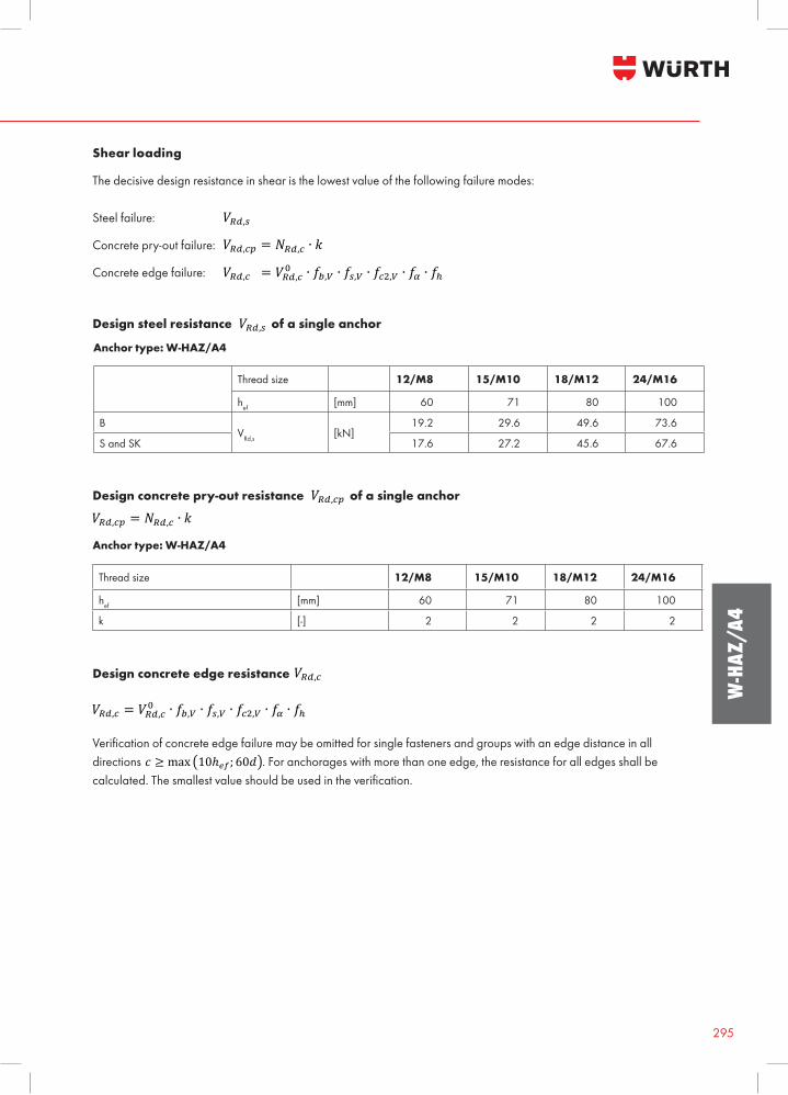
The decisive design resistance in shear is the lowest value of the following failure modes:
Steel failure:
Concrete pry-out failure:
Concrete edge failure:
Shear loading
Design steel resistance of a single anchor
Anchor type: W-HAZ/A4
Thread size 12/M8 15/M10 18/M12 24/M16
hef [mm] 60 71 80 100
BVRd,s [kN]
19.2 29.6 49.6 73.6
S and SK 17.6 27.2 45.6 67.6
Design concrete pry-out resistance of a single anchor
Thread size 12/M8 15/M10 18/M12 24/M16
hef [mm] 60 71 80 100
k [-] 2 2 2 2
Design concrete edge resistance
Verificationofconcreteedgefailuremaybeomittedforsinglefastenersandgroupswithanedgedistanceinalldirections . For anchorages with more than one edge, the resistance for all edges shall be calculated.Thesmallestvalueshouldbeusedintheverification.
Anchor type: W-HAZ/A4
HIGH-PERFORMANCE ANCHOR W-HAZ/A4
Benefits:• Europ
296
W-HAZ/A4
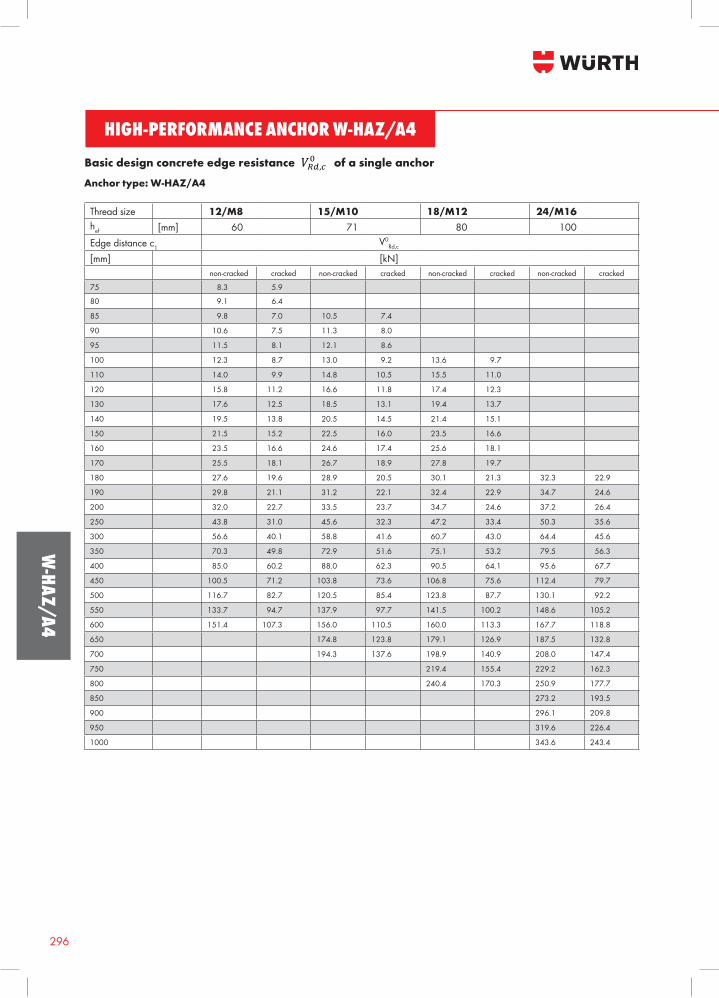
Basic design concrete edge resistance of a single anchor
Thread size 12/M8 15/M10 18/M12 24/M16hef [mm] 60 71 80 100Edge distance c1
V0Rd,c
[mm] [kN]non-cracked cracked non-cracked cracked non-cracked cracked non-cracked cracked
75 8.3 5.9
80 9.1 6.4
85 9.8 7.0 10.5 7.4
90 10.6 7.5 11.3 8.0
95 11.5 8.1 12.1 8.6
100 12.3 8.7 13.0 9.2 13.6 9.7
110 14.0 9.9 14.8 10.5 15.5 11.0
120 15.8 11.2 16.6 11.8 17.4 12.3
130 17.6 12.5 18.5 13.1 19.4 13.7
140 19.5 13.8 20.5 14.5 21.4 15.1
150 21.5 15.2 22.5 16.0 23.5 16.6
160 23.5 16.6 24.6 17.4 25.6 18.1
170 25.5 18.1 26.7 18.9 27.8 19.7
180 27.6 19.6 28.9 20.5 30.1 21.3 32.3 22.9
190 29.8 21.1 31.2 22.1 32.4 22.9 34.7 24.6
200 32.0 22.7 33.5 23.7 34.7 24.6 37.2 26.4
250 43.8 31.0 45.6 32.3 47.2 33.4 50.3 35.6
300 56.6 40.1 58.8 41.6 60.7 43.0 64.4 45.6
350 70.3 49.8 72.9 51.6 75.1 53.2 79.5 56.3
400 85.0 60.2 88.0 62.3 90.5 64.1 95.6 67.7
450 100.5 71.2 103.8 73.6 106.8 75.6 112.4 79.7
500 116.7 82.7 120.5 85.4 123.8 87.7 130.1 92.2
550 133.7 94.7 137.9 97.7 141.5 100.2 148.6 105.2
600 151.4 107.3 156.0 110.5 160.0 113.3 167.7 118.8
650 174.8 123.8 179.1 126.9 187.5 132.8
700 194.3 137.6 198.9 140.9 208.0 147.4
750 219.4 155.4 229.2 162.3
800 240.4 170.3 250.9 177.7
850 273.2 193.5
900 296.1 209.8
950 319.6 226.4
1000 343.6 243.4
Anchor type: W-HAZ/A4
297
W-H
AZ/A
4
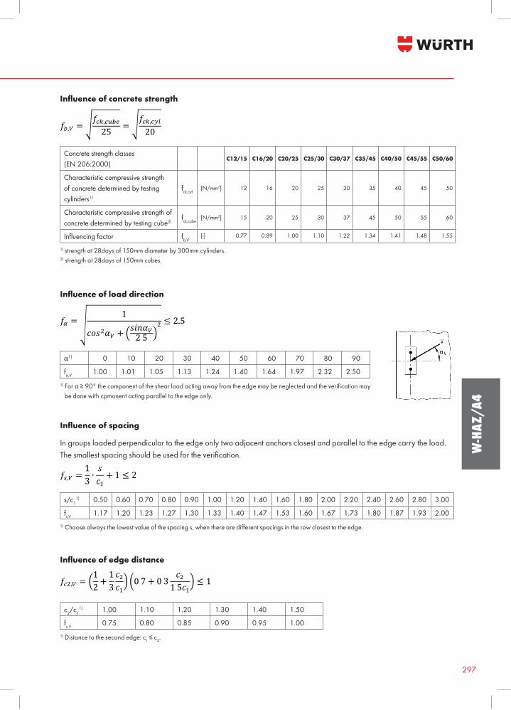
Influence of concrete strength
Concrete strength classes(EN 206:2000)
C12/15 C16/20 C20/25 C25/30 C30/37 C35/45 C40/50 C45/55 C50/60
Characteristic compressive strength of concrete determined by testing cylinders1)
fck,cyl[N/mm2] 12 16 20 25 30 35 40 45 50
Characteristic compressive strength of concrete determined by testing cube2)
fck,cube[N/mm2] 15 20 25 30 37 45 50 55 60
Influencingfactor fb,V[-] 0.77 0.89 1.00 1.10 1.22 1.34 1.41 1.48 1.55
1) strength at 28days of 150mm diameter by 300mm cylinders.2) strength at 28days of 150mm cubes.
Influence of load direction
α1) 0 10 20 30 40 50 60 70 80 90
fα,V 1.00 1.01 1.05 1.13 1.24 1.40 1.64 1.97 2.32 2.501) For α≥90°thecomponentoftheshearloadactingawayfromtheedgemaybeneglectedandtheverificationmay be done with cpmonent acting parallel to the edge only.
Influence of spacing
In groups loaded perpendicular to the edge only two adjacent anchors closest and parallel to the edge carry the load. Thesmallestspacingshouldbeusedfortheverification.
s/c11) 0.50 0.60 0.70 0.80 0.90 1.00 1.20 1.40 1.60 1.80 2.00 2.20 2.40 2.60 2.80 3.00
fs,V 1.17 1.20 1.23 1.27 1.30 1.33 1.40 1.47 1.53 1.60 1.67 1.73 1.80 1.87 1.93 2.001)Choosealwaysthelowestvalueofthespacings,whentherearedifferentspacingsintherowclosesttotheedge.
Influence of edge distance
c2/c11) 1.00 1.10 1.20 1.30 1.40 1.50
fc,V 0.75 0.80 0.85 0.90 0.95 1.001) Distance to the second edge: c1≤c2.
HIGH-PERFORMANCE ANCHOR W-HAZ/A4
Benefits:• Europ
298
W-HAZ/A4
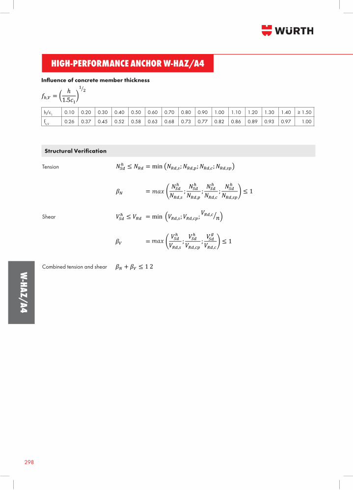
Tension
Shear
Combined tension and shear
Structural Verification
Influence of concrete member thickness
h/c1 0.10 0.20 0.30 0.40 0.50 0.60 0.70 0.80 0.90 1.00 1.10 1.20 1.30 1.40 ≥1.50
fh,V 0.26 0.37 0.45 0.52 0.58 0.63 0.68 0.73 0.77 0.82 0.86 0.89 0.93 0.97 1.00
299
W-H
AZ/A
4
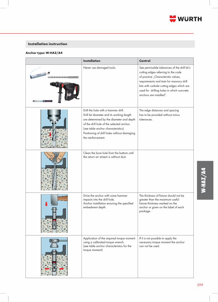
Installation instruction
Installation Control
Never use damaged tools. See permissible tolerances of the drill bit’s cutting edges referring to the code of practice „Characteristic values, requirementsandtestsformasonrydrillbits with carbide cutting edges which are used for drilling holes in which concrete anchors are installed“.
Drill the hole with a hammer drill. Drill bit diameter and its working length are determined by the diameter and depth of the drill hole of the selected anchor. (see table anchor characteristics). Positioning of drill holes without damaging the reinforcement.
The edge distances and spacing has to be provided without minus tolerances.
Clean the bore hole from the bottom until the return air straem is without dust.
Drive the anchor with some hammer impacts into the drill hole. Anchorinstallationensuringthespecifiedembedment depth.
Thethicknessoffixtureshouldnotbegreater than the maximum useful fixturethicknessmarkedontheanchor or given on the label of each package.
Applicationoftherequiredtorquemomentusingacalibratedtorquewrench.(see table anchor characteristics for the torquemoment)
If it is not possible to apply the necessarytorquemomenttheanchorcan not be used.
Anchor type: W-HAZ/A4
HIGH-PERFORMANCE ANCHOR W-HAZ/A4
Benefits:• Europ
300
W-HAZ/A4
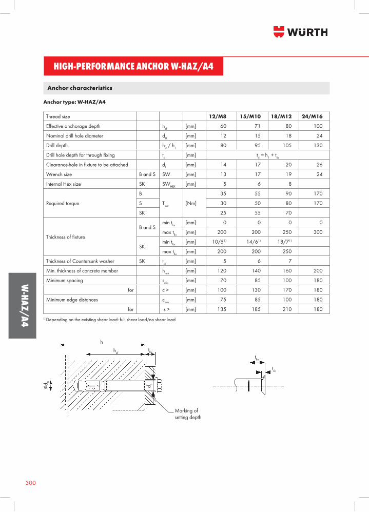
Anchor characteristics
Thread size 12/M8 15/M10 18/M12 24/M16
Effectiveanchoragedepth hef [mm] 60 71 80 100
Nominal drill hole diameter d0 [mm] 12 15 18 24
Drill depth h0 / h1 [mm] 80 95 105 130
Drillholedepthforthroughfixing td [mm] td = h1 + tfixClearance-holeinfixturetobeattached df [mm] 14 17 20 26
Wrench size B and S SW [mm] 13 17 19 24
Internal Hex size SK SWHEX [mm] 5 6 8
Requiredtorque
B
Tinst [Nm]
35 55 90 170
S 30 50 80 170
SK 25 55 70
Thicknessoffixture
B and Smin tfix [mm] 0 0 0 0
max tfix [mm] 200 200 250 300
SKmin tfix [mm] 10/51) 14/61) 18/71)
max tfix [mm] 200 200 250
Thickness of Countersunk washer SK tsk [mm] 5 6 7
Min. thickness of concrete member hmin [mm] 120 140 160 200
Minimum spacing smin [mm] 70 85 100 180
for c > [mm] 100 130 170 180
Minimum edge distances cmin [mm] 75 85 100 180
for s > [mm] 135 185 210 180
Anchor type: W-HAZ/A4
1) Depending on the existing shear load: full shear load/no shear load
tfix
tsk
∅d0
hhef
tfix
Marking ofsetting depth
d f
301
W-H
AZ/A
4
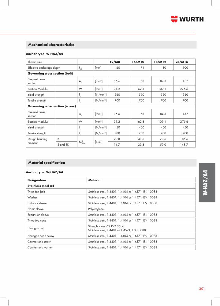
Mechanical characteristics
Thread size 12/M8 15/M10 18/M12 24/M16
Effectiveanchoragedepth hef [mm] 60 71 80 100
Governing cross section (bolt)
Stressed cross section As [mm²] 36.6 58 84.3 157
Section Modulus W [mm³] 31.2 62.3 109.1 276.6
Yield strength fy [N/mm²] 560 560 560 560
Tensile strength fu [N/mm²] 700 700 700 700
Governing cross section (screw)
Stressed cross section As [mm²] 36.6 58 84.3 157
Section Modulus W [mm³] 31.2 62.3 109.1 276.6
Yield strength fy [N/mm²] 450 450 450 450
Tensile strength fu [N/mm²] 700 700 700 700
Design bending moment
BM0
Rd,s [Nm]20.8 41.6 73.6 185.6
S and SK 16.7 33.3 59.0 148.7
Anchor type: W-HAZ/A4
Designation Material
Stainless steel A4
Threaded bolt Stainless steel, 1.4401, 1.4404 or 1.4571, EN 10088
Washer Stainless steel, 1.4401, 1.4404 or 1.4571, EN 10088
Distance sleeve Stainless steel, 1.4401, 1.4404 or 1.4571, EN 10088
Plastic sleeve Polyethylene
Expansion sleeve Stainless steel, 1.4401, 1.4404 or 1.4571, EN 10088
Threaded cone Stainless steel, 1.4401, 1.4404 or 1.4571, EN 10088
Hexagon nut Strenght class 70, ISO 3506Stainless steel, 1.4401 or 1.4571, EN 10088
Hexagon head screw Stainless steel, 1.4401, 1.4404 or 1.4571, EN 10088
Countersunk screw Stainless steel, 1.4401, 1.4404 or 1.4571, EN 10088
Countersunk washer Stainless steel, 1.4401, 1.4404 or 1.4571, EN 10088
Material specification
Anchor type: W-HAZ/A4