Embed Size (px)
Citation preview
William TschudiJune 22, 2009
ASHRAELouisville, [email protected]
High Performance Computingwith High Efficiency
Co-authors:Steve Greenberg, Lead author, LBNLAmit Khanna –Arup North America Limited
• A new high performance supercomputer center for scientific computing in Berkeley, California
• High Performance Computing (HPC) center on first floor• 32,000 square feet computer room
• 7.5 MW initial total power requirement, expanding to 17 MW
• Offices on second and third floors
• Mechanical space below HPC, chiller plant adjacent
• Total gross square feet 126,000
• 2012 occupancy ?
UC Berkeley’s Computational Research and Theory (CRT) Facility
2
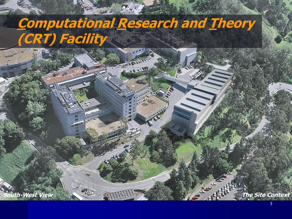
The Site ContextSouth-West View
Computational Research and Theory (CRT) Facility
3
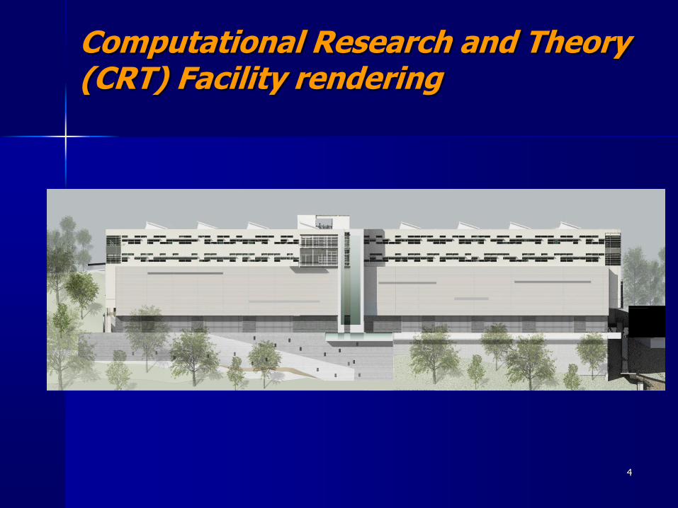
Computational Research and Theory (CRT) Facility rendering
4
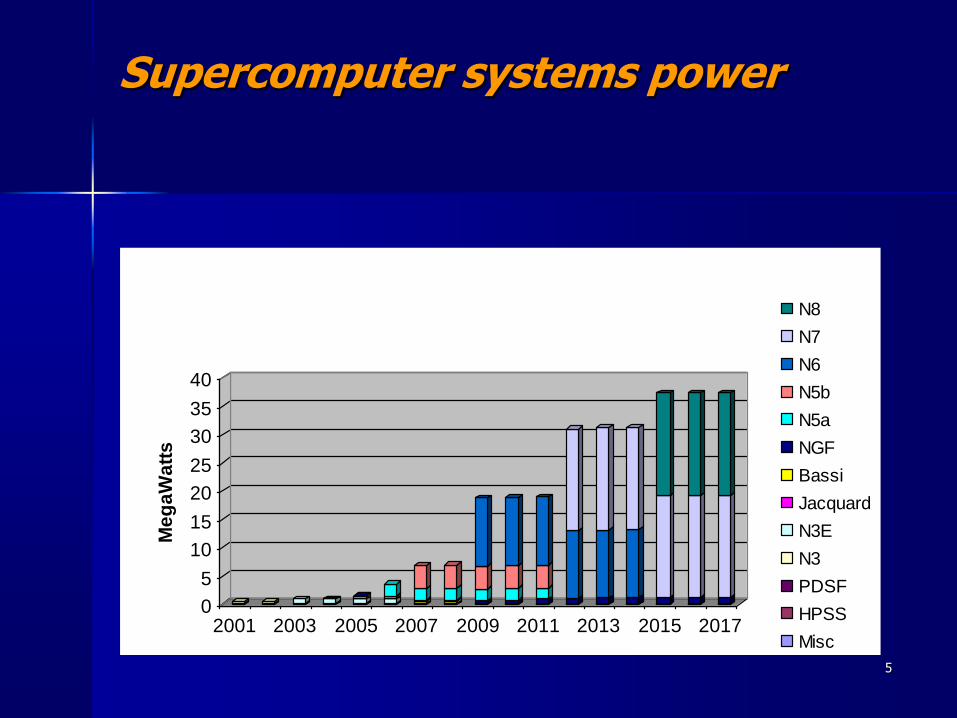
Supercomputer systems power
0
5
10
15
20
25
30
35
40
Me
ga
Wa
tts
2001 2003 2005 2007 2009 2011 2013 2015 2017
NERSC Computer Systems Power
(Does not include cooling power)
(OSF: 4MW max)N8
N7
N6
N5b
N5a
NGF
Bassi
Jacquard
N3E
N3
PDSF
HPSS
Misc
5
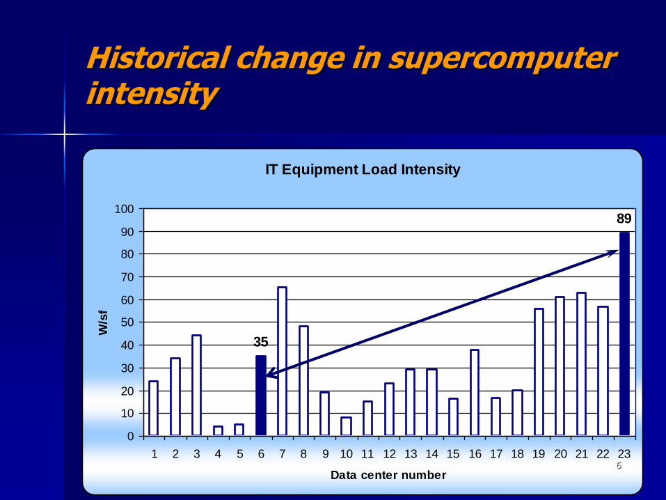
Historical change in supercomputer intensity
IT Equipment Load Intensity
89
35
0
10
20
30
40
50
60
70
80
90
100
1 2 3 4 5 6 7 8 9 10 11 12 13 14 15 16 17 18 19 20 21 22 23
Data center number
W/s
f
6
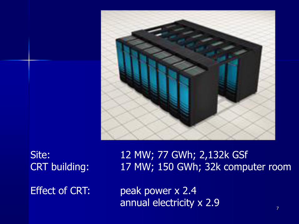
Site: 12 MW; 77 GWh; 2,132k GSfCRT building: 17 MW; 150 GWh; 32k computer room
Effect of CRT: peak power x 2.4annual electricity x 2.9
7
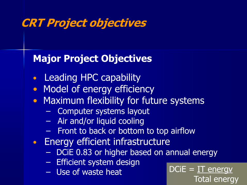
CRT Project objectives
Major Project Objectives
• Leading HPC capability• Model of energy efficiency• Maximum flexibility for future systems
− Computer systems layout− Air and/or liquid cooling− Front to back or bottom to top airflow
• Energy efficient infrastructure− DCiE 0.83 or higher based on annual energy− Efficient system design− Use of waste heat DCiE = IT energy
Total energy8
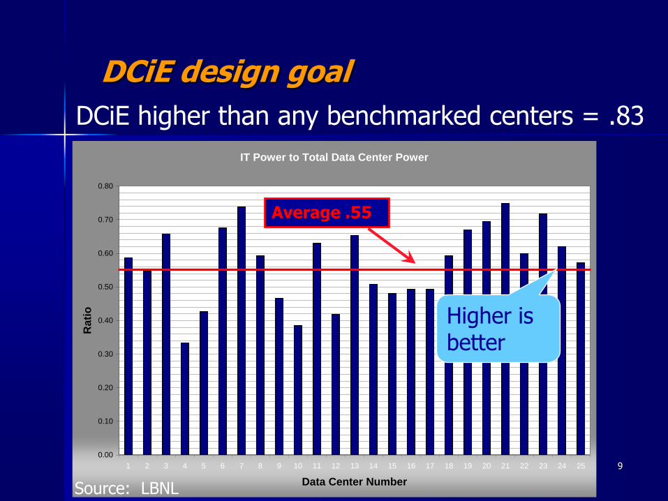
IT Power to Total Data Center Power
0.00
0.10
0.20
0.30
0.40
0.50
0.60
0.70
0.80
1 2 3 4 5 6 7 8 9 10 11 12 13 14 15 16 17 18 19 20 21 22 23 24 25
Data Center Number
Ra
tio
Source: LBNL
Average .55
Higher is better
DCiE design goal
DCiE higher than any benchmarked centers = .83
9
• Many generations of high performance computers over several decades
• High computing load densities: 20 – 30 kW/rack
• Potential mix of air, liquid, or hybrid cooling
• Potentially different temperature and humidity requirements for different computer systems and other IT equipment
• Budget: must be life cycle cost effective
Mechanical design challenges
10
• Minimal requirements for Uninterruptible Power Supplies (UPS) since work involves only scientific computing
• Mild climate suitable for economizer cooling
• Ability to use full ASHRAE TC 9.9 range of recommended temperature and expanded humidity range
• Integrated Architectural - MEP design
Design advantages for efficiency
11
• Flexibility for air or liquid cooling
• Large efficient air handlers
• Integrated modular design
• Liquid cooling capability
• Part load modulation
• Environmental conditions
• Air side economizers and evaporative cooling
• Integrated water side economizer
• Air management• Power distribution• Use of heat recovery
Design features
12
Flexibility for air or liquid cooling
• Advanced HPC systems pushing limits of air cooling
• Systems could be built that:
– Continue to be air cooled
– Have liquid cooled cabinets removing some or all of the heat
– Have liquid cooling to the processors
– Use combination of refrigerant and liquid
– Others?
• Network or storage equipment may continue air cooling even if servers require liquid
13
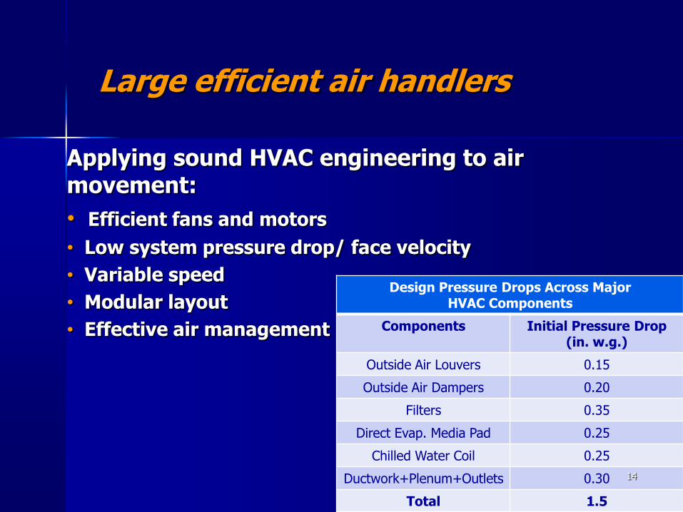
Large efficient air handlers
Applying sound HVAC engineering to air movement:
• Efficient fans and motors
• Low system pressure drop/ face velocity
• Variable speed
• Modular layout
• Effective air management
Design Pressure Drops Across Major HVAC Components
Components Initial Pressure Drop (in. w.g.)
Outside Air Louvers 0.15
Outside Air Dampers 0.20
Filters 0.35
Direct Evap. Media Pad 0.25
Chilled Water Coil 0.25
Ductwork+Plenum+Outlets 0.30
Total 1.5
14
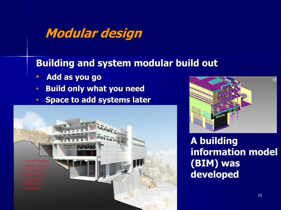
Modular design
Building and system modular build out
• Add as you go
• Build only what you need
• Space to add systems later
A building information model (BIM) was developed
15
• Large headers sized for efficient operation for future loads -even higher efficiency in the interim
• All pumps, fans, and compressors are variable speed
• Unequal chiller sizes for better turn-down and load matching
• Optimal control for maximum overall plant COP at any load and outdoor condition
• Space for additional chillers and towers for future loads
• Headers, valves and caps for modularity and future flexibility allow additions without shutting down
Modular cooling plant
16
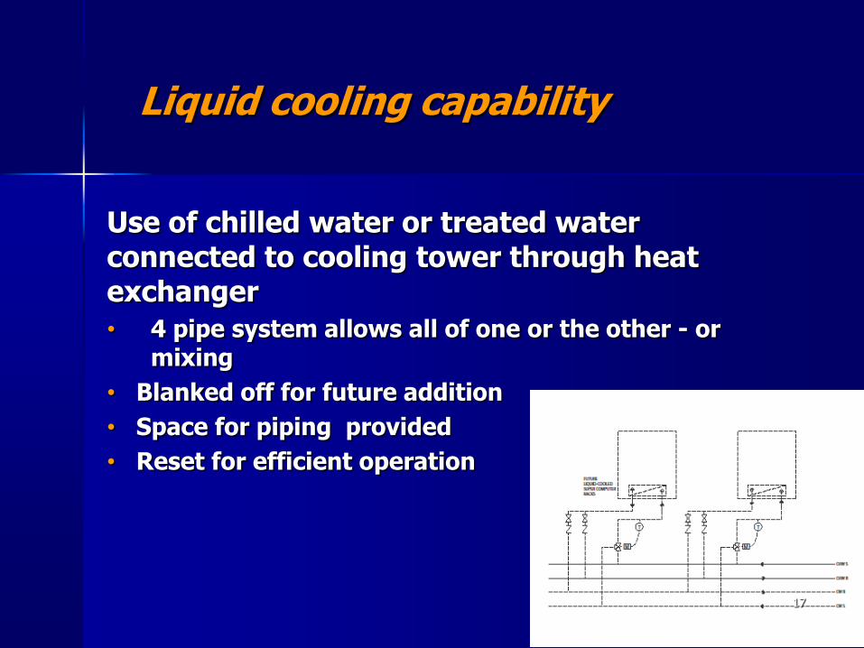
Liquid cooling capability
Use of chilled water or treated water connected to cooling tower through heat exchanger
• 4 pipe system allows all of one or the other - or mixing
• Blanked off for future addition
• Space for piping provided
• Reset for efficient operation
17
Part load operation
HPC systems operate fully loaded however systems will be added and removed over the life of the facility varying the cooling requirements significantly
• Modular
• Variable speed everything tower fans
chilled water pumps
condensing water pumps
chiller
exhaust fans
main air handler fans
• Controls18
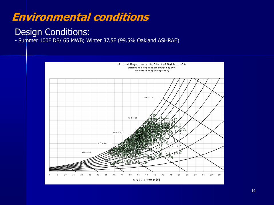
Design Conditions: - Summer 100F DB/ 65 MWB; Winter 37.5F (99.5% Oakland ASHRAE)
Environmental conditions
An n u a l P sych ro m etric C h art o f O ak lan d , C A
(re la tive h u m id ity lin e s a re s te p p e d b y 1 0 % ,
w e tb u lb lin e s b y 1 0 d e g re e s F )
0
0 .0 0 1
0 .0 0 2
0 .0 0 3
0 .0 0 4
0 .0 0 5
0 .0 0 6
0 .0 0 7
0 .0 0 8
0 .0 0 9
0 .0 1
0 .0 1 1
0 .0 1 2
0 .0 1 3
0 .0 1 4
0 .0 1 5
0 .0 1 6
0 .0 1 7
0 .0 1 8
0 .0 1 9
0 .0 2
0 5 1 0 1 5 2 0 2 5 3 0 3 5 4 0 4 5 5 0 5 5 6 0 6 5 7 0 7 5 8 0 8 5 9 0 9 5 1 0 0 1 0 5 1 1 0 1 1 5 1 2 0
D ryb u lb T em p (F )
W (
lb/l
b)
W B = 3 0
W B = 4 0
W B = 5 0
W B = 6 0
W B = 7 0
19
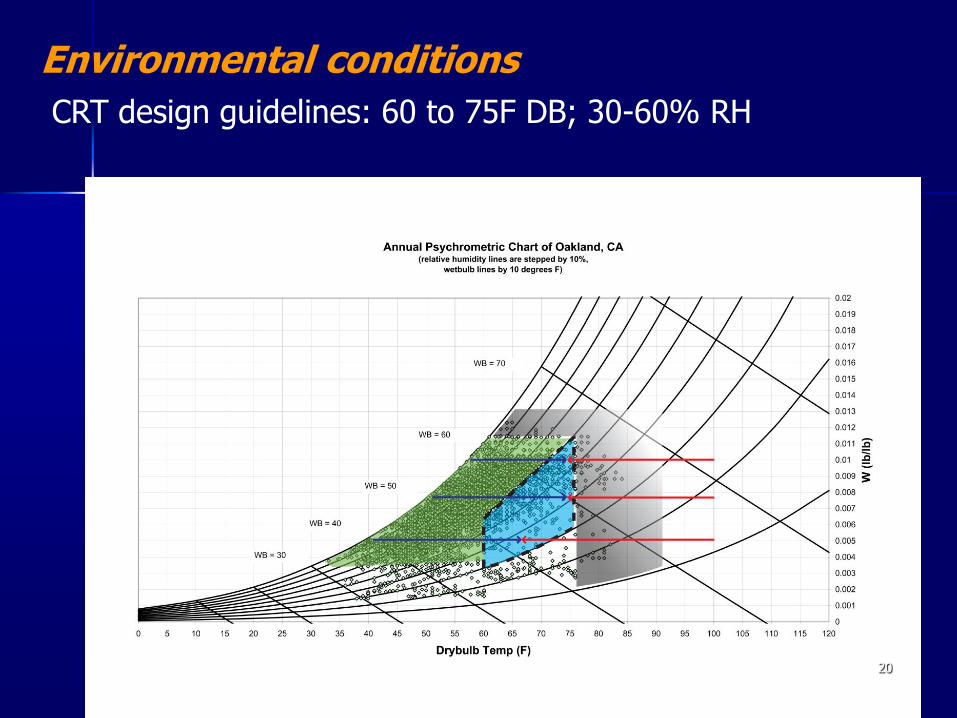
CRT design guidelines: 60 to 75F DB; 30-60% RH
Environmental conditions
20
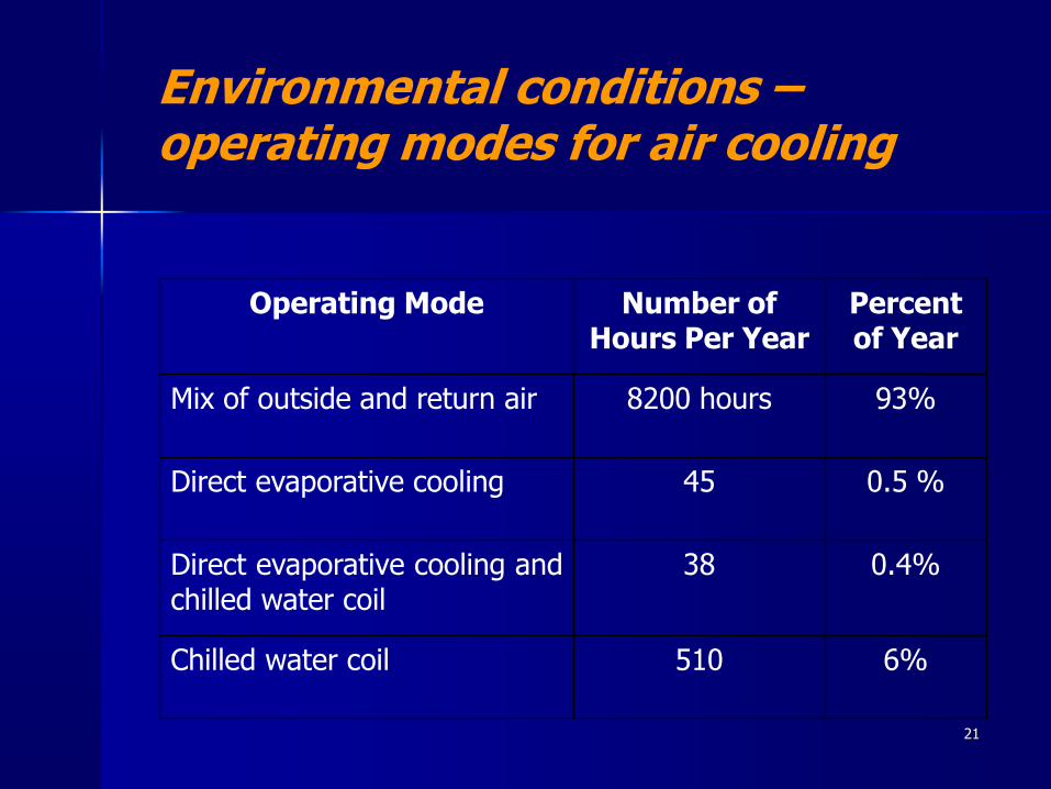
Environmental conditions –operating modes for air cooling
Operating Mode Number of Hours Per Year
Percent of Year
Mix of outside and return air 8200 hours 93%
Direct evaporative cooling 45 0.5 %
Direct evaporative cooling andchilled water coil
38 0.4%
Chilled water coil 510 6%
21
• Direct evaporative cooler doubles as humidifier
− Uses sensible heat from equipment
• Humidity allowed to float within recommended range
• Evaporative cooler has more pressure drop but lower life cycle cost relative to spray nozzles or ultrasonic humidifier
Air economizer and evaporative cooling
22
Condenser
Evaporator
Condenser
Evaporator
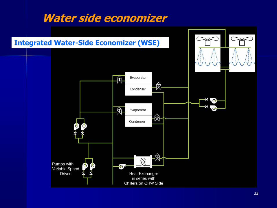
Water side economizer
Integrated Water-Side Economizer (WSE)
23
• Isolation of hot and/or cold aisles on the HPC floor
− minimize mixing and recirculation
− CFD model to predict air pressures for consistent air flow
• Divisible space under and above raised floor
− allows for different environmental conditions for different computing systems
Air management
24
•Hot air or water will be available
•Warm enough to preheat air in CRT and nearby laboratory and office buildings
•Enough heat available to eliminate all space heating energy usage in these buildings
• Interconnection also used for heating water to CRT (at start-up)
Heat recovery
25
•480 volts to the racks
− Minimizes conversion loss
•Minimal UPS (under 10% coverage)
− Selection of delta-conversion or double-conversion with bypass to minimize losses
• No need for redundant power supplies
Power distribution efficiency
26
Predicted HPC Performance
• DCiE of 0.90-0.95 based on annual energy
• DCiE of 0.83-0.90 based on peak power
• No credit taken for heat recovery
27
Questions?
28